

Rik Thistle
-
Posts
804 -
Joined
-
Last visited
Content Type
Profiles
Forums
Gallery
Events
Everything posted by Rik Thistle
-
 Popeye, Thanks. It was a fun build. These little engines and their full sized cousins produce a lot of power ...some say a can of spinach is added to their boiler tanks at the start of each day 😉 This gentleman runs a professional steam powered workshop using no equipment made later than 1925* .... https://www.youtube.com/watch?v=9WXHNBMLZZM He deserves a medal for doing this. Interestingly, steam still provides most of the power we use today. Richard *He does admit to using some modern measuring equipment but tries to keep it out of sight.
 -
kit review 1:32 Fifie – The Scottish Motor Fishing Vessel by Amati
Rik Thistle replied to James H's topic in REVIEWS: Model kits
Clive, She looks ready to get to work. Well done. What a good lloking model. Richard -
Hi all, I think I've now got most of the workforce back in the shipyard, after them disappearing off to enjoy the Summer. So just a short post to get the ball rolling, again. I had previously done some initial work on the masts eg turning diameters etc in my little lathe. So I will continue with the two masts. Below - I glued the Bolsters to the 'trees'. Then I sat and stared at the Mast Drawing plan (Sheet 5) for quite a while, and realised that there is a lot going on with these two similar masts. So proper parts organisation seems a good idea, as did much more staring at Sheet 5. Below - the two Topmasts had the 4mm square (Edit: My mistake, should be 3mm square, darn...so sanding down to 3mm) section milled on the end. This turned out fine - the starting size was a 6mm diameter, so I tentatively took a 1mm deep cut, gently holding the protruding section in the Proxxon vice. I thought it might start to flex as I got to the 4th side but by going slowly all was fine. I have a dividing head, but instead used a set square resting on the bed and the freshly cut side to ensure 90 deg rotation - that worked OK. As I mentioned, there is a lot of detail on Sheet 5 that I need to reassimilate. It wasn't a good idea to leave Flirt for months...I should have tried to do a little each week. Ah well, live and learn. Richard
.thumb.jpg.ace64b651831e5c68a6fd9a76d181014.jpg)
.thumb.jpg.6dc639cfb4d854eb91d13595802588ff.jpg)
.thumb.jpg.6db0ed55b3f5c124a73f5c9557f1171c.jpg)
-
Well done Glenn; she's a beauty...and well lit at the window. Richard
- 160 replies
-
- 2
-

-

-
- Alert
- vanguard models
- (and 1 more)
-
Need help from a model maker in California !
Rik Thistle replied to Ekis's topic in Wood ship model kits
I would be interesting to know what specialist delivery companies do different. Do they control the shipping environment completely from A to B? Here is only one stage in the delivery of 'normal' packages ... https://www.youtube.com/watch?v=jF_w7uSnOj0 From what I've seen and know, marking normal packages with Fragile and/or This Way Up makes no difference whatsoever, unless the item is mounted on a pallet and moved by forklift so improving it's survival chances somewhat. If a valuable three masted ship with lots of rigging, say, was being shipped around the world then what is the optimum solution?... - Design the hull (the part with most mass) so that it can be rigidly fixed to a base plate, and leave the masts/rigging mounted and in free space. - Remove parts from the ship that might work loose in transit and put them is a separate box rather than them becoming missiles. - Securely mount the base plate in an extremely tough box that always maintains a gap of at least 150mm from any part of the ship. - Do not use peanut type packing, or any for that matter, that can contact any parts of the ship. - One of the flaws with the above is that the masts, if suddenly accelerated back and forth (and upside down), may not be able to take shock loading. - Do 'insured' packages have a big 'Insurance' label on them that the handlers see so know that their employers will not be happy if those particular goods get damaged? Just thinking aloud. Richard -
Ron, Yes, I've watched a lot of his videos especially his one on the Stuart Engine ... 'MAKE A STUART STEAM ENGINE pt 1 of 9 tubalcain' https://www.youtube.com/watch?v=6WZykfoKIsA&list=PL6HIFled82YUVmxw4RysNJron441QhyFO He's very helpful. Another one is BlondieHacks...she's quirky but likeable and is good at explaining things. And, as you say, there are a load of videos on sorting out mini lathes. I've lost track of how many I've watched 😉 I got my lathe from ArcEuroTrade in the UK - these lathes all seem to come from one or two companies in China that make the raw castings, then Seig and others buy those castings, machine them up to their desired specs and add USP features. I believe ARC actually spend time in the Sieg factory explaining what they want and the desired quality level that must be met. There's 3 or 4 distributers in the UK of the lathes; they're all pretty good. I wouldn't buy direct from China or eBay since it is a bit of a pig in a poke purchase. At least with a local distributer you have someone you can phone up and discuss things with. Also these distributers stock all the lathe add-ons/tools that one could ever wish ...I'm suspecting it's a bit like the old Gillette safety razor...the handle was sold at a loss and the profit made on the blades! Richard
-
Thanks Mark. All the pics were taken with my Moto G phone, which tends to be nearby most of the time, so they're not the best and some parts are slightly out of focus (...there's probably a setting/optimum distance to reduce that). But the phone's 'convenience factor' is high...especially when I'm in the workshop and I just need a quick pic for reference, and then later attach the phone by USB cable to the computer to save the pic. I have better cameras but they are bagged away...laziness rules. As I mentioned earlier, the engine was a pleasure to build and made a good summer better. After surfing many YT and blogger websites picking up tips, I can see that there are a lot of hobbyists (amateur engineers/scientists) who follow more than one interest which can only help improve their overall competence. Yes, it's a great way to spend one's time, learn new things and 'meet' interesting helpful people. Richard
-
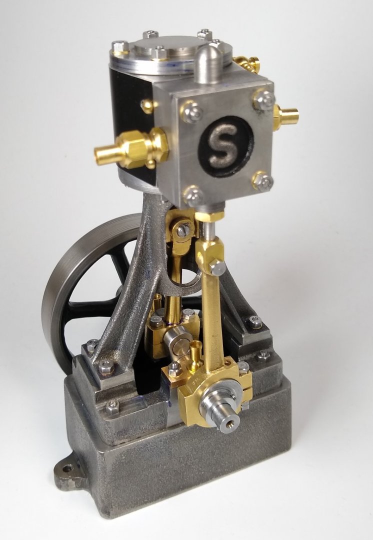
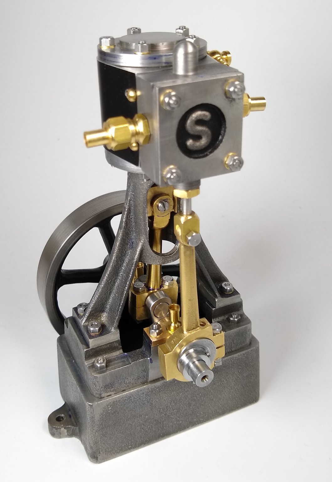
Hi all, So here is my final post (for the moment*) on this build of the Stuart 10V completely assembled and with a minimalist paint job. I know most industrial and model versions of the engine generally have a predominately Green paint finish with touches of Red, but I really like the way it looks at the moment - leaving most of the metalwork bare let's one see how the parts were machined. The kit came with a Black anodised Cylinder surround and I used that as my colour cue - I added Satin Black to the Flywheel spokes and inner rim, and also to the backdrop for the letter 'S'. Well, that's it ...a short Build Log and thanks to all for popping in and the Comments and Likes. Richard * The Reversing Gear will be added to the Build over the next 12 months, but now back to HMS Alert....oops, HMS Flirt, it's been a long time.
.thumb.jpg.be00a69e8d32734bc602c0e6a44597df.jpg)
.thumb.jpg.8e50e4c7969e1552a10036ab0695e480.jpg)
- 55 replies
-
- 18
-
-

-
'More tape?' Bruce, there was more tape used than you could shake a stick at 😉 ....and it was actual Duck tape....no expense spared! I think that having proven the engine moves properly, when connected to my hand drill, I should consider doing a thorough investigation in to compressors and air tanks. I will be adding the Reversing Gear kit to it sometime in the next 12 months so the engine will deserve a decent power source to prove it's functionality., even if it's not an actual boiler...yet. Richard
-
'vacuum' ... I tried it using my Panasonic upright, but the air exit port is a large grill that isn't easily turned in to a funnel. I also tried using the the vacuum's suction port and connected that to the engine's exhaust port ie sucking the piston down rather than pushing it down...the Flywheel actually moved about 1/4 turn but was struggling. Also the vacuum's motor was beginning to slow down and get a bit warm ;-( The vacuum's suction tube has an ID of about 30mm and the engine's ports are about 3mm ID. So that's about a 100:1 reduction in CSA. Probably too much. Still thinking though.
-
"...vacuum cleaner..." Now there's a thought. I'm away to grab some duct tape and bits of tube, thanks.
-
Hi all, A few more picture and notes below, to later be followed with a final post of pics of the 'paint job' and thoughts. Below, the Eccentric Strap having it's 5/8" dia hole bored out. Towards the end of the build I came to realise that boring and then reaming a hole was probably overkill ....boring seemed good enough. Reaming was suitable for smaller holes that my 8mm square section boring bar wouldn't fit in. Even then I do have an old 1/8" dia hand made boring bar from back in the day, so I could probably bore out quite small holes with it. I'm saying it is the Strap being machined on the lathe below, but it might be the Conrod....it's moving too fast to be sure, but my money is on it being the Strap. Back to the mill with the Eccentric Strap to drill a 7BA clearance hole through on one side. The Strap is then cut on that side (using a Dremel cutter that happened to fit the mill's 3mm collet). The 7BA screw can then 'close' the hole around the Eccentric Sheave that revolves in the hole till it is a nice sliding/rotating fit. Seen above is the miniature Faithful set square that I bought shortly after getting the mill. As it turned out this was an excellent purchase and has become one of my favourite multi-purpose tools. It's quite well made nestling accurately into my larger Moore & Wright set square. Below, tapping one of many holes in the engine. using my trusty Eclipse No 245 tap wrench (1/8"-1/4", 3mm-6mm). This is the best tap wrench I have ever used since the dimples on the end encourage finger tip gripping only and the flat shape aids visual horizontal alignment. I also owned it's little brother, the No 244 but it disappeared years ago....however....it miraculously turned up at a friend's house the other day....so I'm very happy about that 😉 However I was saddened to see it described on eBay as 'Vintage'...gulp. Below - Starting to finally fit parts together , checking alignment etc. I lost count of the number of times I fitted/removed the fixing screws and nuts. I ended up buying a set of BA box spanners to speed that up and to complement my BA spanner set. Finally, test fitting the gaskets and adjusting the valve setting. Towards the bottom of the picture is the oft mentioned but never spotted Eccentric Sheave (circular, silver coloured part) which is locked by grub screw on to the Crankshaft. The Sheave's purpose is to drive the valve up and down as the Crankshaft rotates and in synchronisation with the piston movement. I've tested the finished engine using a power hand drill clamped on to the Crankshaft - it seemed to work fine. But really, it should be the piston powering the crankshaft - not the other way around. I'd like to at least 'properly' test the engine with compressed air which leads me to thinking about purchasing a model airbrush + compressor + tank for painting, with the compressor + tank part also being suitable to drive the steam engine. I did some rough calcs the other week about air flow rates -v- engine consumption etc but if anyone has any thoughts/advice/experience on a suitable UK item please feel free to fire away. Catch you soon, Richard Edit: Air compressor now ordered, so a more life like test will be possible. And the compressor will one day drive an airbrush also 😉
.thumb.jpg.9aab1b204f27355dbb38209768d19ed6.jpg)
.thumb.jpg.8ab59ce4ad39579f3afe43f66325f94a.jpg)
.thumb.jpg.879cf214ec7e8d39526cf14f9f7d4fa7.jpg)
.thumb.jpg.f0950e7bacb1bddc5e3a1e2c246833d7.jpg)
.thumb.jpg.c3f18ffd021f8191d287786fc33c1fc1.jpg)
-
Mark, The grooves are actually flush and even running my finger over them can't tell they are there. I'm quite happy to leave them there as they add a bit of 'character', or so I'm telling mself. And yes, the wheel has had P1000 Emery run over it. My lathe doesn't have Compound or Cross slide power feeds, sadly. Well, it does have a lead screw that I can engage but I don't trust the slop in it at the moment. Also, the slop in the saddle was ridiculous when I first got the lathe so I fitted a lock and that really tightened things up. Bangs for bucks the lathe is very good but it's still at the low end of the market. But for my purposes I'm very happy with it. Richard
-
Thanks Roger, I suspect that if you can machine small brass parts then you can pick up general workshop practice pretty quickly. Shadowing someone (an Elmer with a home workshop?) for a few weeks whilst they use their workshop tools is a great learning method. Then they can start gently letting you have a go on the various tools. And I'm sure you know this, but ALWAYS wear safety glasses, and avoid having any dangly clothing that can get caught up in things. With new machines I do a good 5 mins of dry rehearsals using the Emergency Stop buttons, to train memory muscle. Sorry, if I sound like 'teacher' 😉 Richard
-
Hello again, Some more snippets from my Stuart 10V build follow. As I mentioned earlier, the build order may seem it is a bit haphazard but was influenced by such things as turning all the 10mm dia parts in the lathe's 10 mm collet since that was already set up, leaving a part half finished whilst I awaited the delivery of a tool (eg (3/4" reamer), having to go back to an earlier part since I had not appreciated how well it needed to fit a later part etc etc. First, facing off the Standard's top surface in the 3 jaw chuck. I used the same Ikea 'mandrel' from earlier, this time showing the anti-rotation peg/screw I had fitted. Below - I then mounted the Standard on the Faceplate to bore out the 5/8" dia hole. That went quite well and resulted in a smooth enough finish. There was a little spring on the boring bar but repeated in-outs at the same setting shaved off a few tenths of a thou" each time. Just to make it super smooth and to size all the way down the bore I used a 5/8" reamer driven by hand power - that worked fine. On to the cast Crankshaft Bearings, which arrived as one piece to be later cut in two. The top surface of the casting was filed smooth as much as I dared since there was little extra material on that face. The Sole Plate 'U' channel was also hand filed out to accept the bearing. After cleaning up the bearing surfaces with a file and cutting it in to two pieces (one bearing each side) I had read that the bearing would actually fit centrally in a 3 jaw chuck with a little bit of packing, which it did. The hole for the Crankshaft was then roughed out and circular bosses added. Below- Next was to clamp the two bearings in the Sole Plate and pass a 9/32" reamer though. At that time I hadn't appreciated the underside of the bearings that sat on the Sole Plate mounting faces should have been machined flat (and together) rather than gently hand filed. Centre pops marked what bearing went on what side of the Sole Plate. As mentioned, the undersides of the bearing should have been machined flat....the toolmaker's clamp highlights how out of line they actually are ...it's actually quite subtle, but when it came to tighteneing up the nuts on the bearings, the Crankshaft went from free running to locking up with the last half turn or the fourth nut...darn! I later machined the offending faces. The Crankshaft assembly was fabricated from two 9/32" rods, two Crankwebs and a Crankpin. This was a sligtly tricky process but turned out OK - all parts were pinned and Loctited together. Earlier Stuart kits supplied the Crankshaft as a one piece casting. Below are the two Crankwebs (for the Crankshaft) being drilled out to size to accept the rods. I had to use my bench drill since it had a deeper reach and could take the large drill. The micro mill only goes up to 3mm dia. Yes, a larger mill is on the 5yr wishlist. Below- marking out the Conrod. Brass is a lovely material to work with but it doesn't half produce tiny little spears that home in on my finger tips. The Conrod connects the Piston Rod/Crosshead and the Crankshaft at the lower half of the engine.. Above - the hole centres need to be reasonably accurate, but there is adjustment in other parts that can compensate for a 0.5mm error, say. Sorry about switching back and forth between Metric and Imperial ....that's how I was trained and I can generally keep track on these values in my head. Below- The Eccentric Strap, which works the Slide Valve assembly, which in turn allows steam to enter the Cylinder. I think the pic shows me fixing a mistake....I had centre popped the hole for the Eccentric Sheave hole, cut the Strap end in half and then realised the centre was in the wrong place. So I'm about to face off extra material to bring things back in line. Below - The Bottom part of the Sheave that was sawn off...it will be faced, clamped to it's mating half and then two fixing holes drilled in both to hold the two halves together whilst the 5/8" dia Eccentric Sheave hole is drilled/reamed. Below - the Cylinder's bottom end cover being drilled on the MF70s Dividing Head....that worked fine. And now using that Cover as a template to spot the fixing holes through on to the cylinder. My small toolmaker's clamps hadn't yet arrived so I improvised 😉 The Cylinder is peppered with drilled holes. Here we are drilling through at an angle from the cylinder chamber (on both ends) to one of the three apertures on the cylinder Valve Chest face. The little vice was more than strong enough to hold the Cylinder in place during this operation, thankfully. And... a Cylinder with a Coke bottle cap finish at one end of it's 3/4" bore. This was the result of not leaving well enough alone. I had bored the hole out to a good finish, but it was time for another reamer (3/4") delivery so I used it, badly. It's not pretty but lets just say the lighting make it look waorse than it really is and leave it at that...cough. Below - Starting to see the home straight now. Here is the flywheel being turned to almost finished dimesions on the 4 jaw. Once the centre was drilled out it was fitted on a mandrel and finish machined. I had read that the dominant visual feature of a flywheel when it is rotating is usually the part you can't machine ie the inside of the cast rim....hence the 4 jaw for centering on that feature. I did file the inside rim reasonably smooth but not to a turned quality. Below- It's starting to look a bit more like a vertical steam engine. Still loads of fixing holes to be drilled and tapped though. Above - Interesting to note the narrow bands on the Flywheel perimeter....I think this is due to the lathe's Compound slide lead screw having a slight bend in it....each of the bands is 1mm apart which matches how far one complete rotation on the Compound slide's handle moves the tool point. This was another reason for building the Stuart 10V ...to unearth any lathe/mill parts that weren't quite right and needed fixing. Below - The Valve Chest, the brains of the operation. The little hollowed-out brass cube slides up and down over the three openings on the Cylinder only ever connecting two openings at once. More thoughts on the above may come to me over the following days/months so I will tweak the posts as necessary. I think that's it for today then. Hopefully tomorrow I'll be able to show the finished engine. Richard
.thumb.jpg.0a5ced1979d619a57a3f82b7e1436074.jpg)
.thumb.jpg.b1d0d7531bf78afe08b5ad9fc97ba33a.jpg)
.thumb.jpg.a1aa9119f55ef34fd99b36b8b5b3d166.jpg)
.thumb.jpg.bc57430f5ce40665349f36fa1a4a8b89.jpg)
.thumb.jpg.af805eb31e255914221bde191fd1615d.jpg)
.thumb.jpg.2e437bfe561d0a4cfd4a449bb1a66561.jpg)
.thumb.jpg.a42ad71f343bba4b3fd89874bc7b97e7.jpg)
.thumb.jpg.3ea8d92090e2e8b6b72057a9c51b2987.jpg)
.thumb.jpg.6b4033b633a187a256e914be2ea6cbd0.jpg)
.thumb.jpg.3c0dba312f2512d192dba803c0723254.jpg)
.thumb.jpg.678d2c38bed03f79fe651c1f2acc82bd.jpg)
.thumb.jpg.7e0cf465fc551f5aa88a857a4456d623.jpg)
.thumb.jpg.176d4df40d2050f70c2b09e2fb046b4a.jpg)
.thumb.jpg.90fb47216f23501e647a53da576da903.jpg)
.thumb.jpg.660c00c1edbb2be8d334d46595083eee.jpg)
.thumb.jpg.a78aa464efe4ef1c1de0229aac709ef1.jpg)
.thumb.jpg.8d273be12ba8dfd6ad73481a1846bfe6.jpg)
-
Mark, I can only be inspired. The skills and abilities of these folks are to be admired....eg If only non-technical folks understood what is needed to produce those works of art the world might be a better place. That's not to say other disciplines lack merit, but I do feel that there has been a trend over the last 30 - 40 yrs to push younger folks towards the less hands-on careers. Anyway, I'll have a good read through that link over the weekend, thanks. Richard
-
Hi all, A short post to start the day with, focusing on three of the main castings. Below, L>R, - the Standard, which is the structural link between the reciprocating stuff (the piston) and the rotating stuff (the crankshaft), - the Sole Plate, which fixes the relative positions of the Standard and the Crankshaft - and the Box Bed, which is attached to the ground, and adds stability and strength to the structures above it. It may have other functions (vibration dampening?) that I'm not yet aware of - I'm thinking real world scenario. From the above.... - the Standard has been cleaned up by eye on the sanding belt to add approximate squareness and also to remove some of the hard casting surface layer. - The Sole Plate has had it's top and bottom surfaces machined to size on the lathe using the 4 jaw chuck. The hard casting surface is nicely highlighted (the shiny perimeters) on the Sole Plate...in places it is up to 1 mm deep. I had started off by using HSS cutting tools but quickly switched to carbide tipped tooling to cope with the hard layer. The Plate also features cast-in dimples to indicate where fixing holes should be drilled. The positional accuracy of those dimples should generally be taken with a pinch of salt! - The Box Bed had it's top and bottom surfaces (and mounting lugs) milled flat using the tiny MF70. I was keen to experiment with different finishing methods (lathe, mill, filing etc) to get experience and see what worked best. The milling was quite a long process taking tiny cuts at a time...probably the hardest part being winding the table back and forth. I also drilled and tapped 7BA holes in the top surface along with 'I forget' sized holes on the mountimg lugs. Below, the Standard (unmachined but sanded) being visually checked on the Sole Plate and Box Bed. The circular hole running through the Standard is important in that it needs to be aligned correcly with the components it interfaces with...more in later posts. Below, the Standard being held in the lathe courtesy of an Aluminium tube running down it's (roughly cleaned up) bore. The tube was from a piece of old, dismantled Ikea furniture (lamp stand?) which was stored in the 'that might come in handy one day' bin....well it did 😉 Luckily the tube had a threaded end and matching countersunk screw which forced the Standard against the jaw surface. IIRC, I also added a peg to the tube to stop the Standard rotating under cutting loads. Above, the Standard's two feet cleaned up nicely. As I was making the 10V engine I was only occassionally taking pictures mostly for my own reference rather than for a Build Log. But with 20:20 hindsight I may have taken just enough pics to form some kind of haphazard log. So apologies now, if I tend to jump back and forth between items as I post. This was meant to be a very short first post for today, followed by a longer post (ie more pics) later today. I'll see how I feel 😉 All the best, Richard
.thumb.jpg.135ee194c3cc2f8c84c915974f5d95b6.jpg)
.thumb.jpg.c28ea3859c9243f4f2fd7a9b8ea28900.jpg)
.thumb.jpg.e621fdd4716d052df9c27791a52e8b6b.jpg)
-
Bob, Thanks for the info; I'll have a good read Yes, there seems to be a thriving market for quality steam models. Keith Appleton not only makes and sells his own superb models but (I think) acts as an agent for other modellers ... 'SOME SUPERB MODEL STEAM PLANTS - NOW SOLD' - https://www.youtube.com/watch?v=Najs8o412Oo&t=348s Even Bonhams are in on the act .... https://www.bonhams.com/auctions/25163/lot/310/ I doubt if any of the modellers are in it to make money, but rather for the sheer pleasure of building and operating the equipment, and of course, learning. In addition to Keith Appleton, a couple of my favourtie YT sources are Andrew Whale and Tinker John Both explain clearly what they are doing, the mistakes they make and the equipment they use. I'll mention others as I go along. So far, I've spent (too) many hours watching YT builders and reading websites. I suspect my small but growing 'model ship building library' will soon have some new companions from the 'steam model' world eg Where the Rails Meet the Sea which I saw mentioned on a different thread in this forum the other day. I'll try to post some more pics of my build later today. Richard
-
Funny you should say that Bob .... https://www.mainsteam.co.uk/mainsteammodels-gallery 😉 I've spent quite a bit of time reading through Keith (Appleton) website, and there are many glorious examples of what can be done with steam engines. I find it a fascinating subject. Richard
-
Hello all, In June 2021 I bought Stuart Models 10V steam engine castings set.... https://www.stuartmodels.com/item/39/stuart-10v-unmachined Plan being to get me more outdoors ie in the shed with the door open enjoying the great summer and nature flying and buzzing all around. The build took about 12 weeks using a Sieg SC2 lathe, Proxxon MF70 Micro Mill, bench grinder/sander, bench drill, hand tools .... and a calculator. It's many decades since I did 'metal work' professionally but after a few weeks a lot of it 'came back to me'. So did making mistakes and then figuring out to remedy them ;-). This was a totally fun project. I have since bought the Stuart 'Reversing Gear' kit of castings, what with this being a 'ship' website and steam engines on boats/ships needing a reverse gear. And that will be next summer's project. Also, there is the tiny seed of an idea in my head that one day I'll add a boiler, build a waterproof model boat, fit servos etc ....add the lot together and go RC sailing...but that's in the future, maybe. Anyway the Stuart box arrived in late June.... A simple but sturdy cardboard box, with the metal contents held in place with a strong, transparent sticky covering....they weren't going anywhere! The 'paperwork' is a single large sheet with the parts' detail drawings on one side, a Parts List, Exploded View and very basic instructions on the other side. It could be argued that the drawings did kinda dimension all aspects of the parts that needed machining, but it was prudent to study those drawings closely and also consult other sources. An inventory check showed everything was present..... One of the 'other information sources' is shown above - the booklet by Andrew Smith. It has gone through a number of revisions and gone as far as converting BA thread sizes, dimensions etc into Metric... hmm. Below a first look at four of the main castings...clockwise from top left, Sole Plate, Cylinder, Standard and Flywheel. Castings sometimes have a very hard outer surface (due to cooling) that makes machining difficult. So I proceeded to skim as much as that hard surface off as allowable, using files and a sanding belt. Note: I say 'allowable' since some of the casting surfaces were right up against the borderline regarding what the finished size would be. Above, a slightly blurry pic of the Box Bed having it's top and bottom surfaces machined flat and parallel, and square to the rest of the item. (Edit: It looks like I was actually drilling out the mounting lugs rather than milling flat the top and bottom surfaces....that milling had been done earlier) The mill above really is 'micro', with the largest diameter cutter being 3 mm. However going slowly and taking no more than 0.25mm (10 thou) cuts max, a reasonable result is achievable. I had spent some time fettling the mill on arrival eg adjusting the gibs, adding ball thrust bearings in the Z axis and a Z axis digital readout. So it all worked fine...for a while (...blunt tooling tended to 'grab' quite easily). Below, centre drilling the two main fixing holes. I later bought stubb drills which were the proper tool for that job and have a slightly longer reach (I think the stubb drills might be shown in the pic above). OK, that's it for today. I'll post more over the next few days. Spoiler alert. I have already finished the engine and successfully 'run' it using an electric drill attached to the crankshaft. Which is putting the cart before the horse, since the power is meant to come from the steam in the cylinder, which in turn drives the flywheel (attached to the crankshaft). But building a boiler, or even sourcing compressed air is for a later day. Catch you soon , Richard PS: I really do plan to now get back working on HMS Flirt.
.thumb.jpg.be6106787b169776aed9d5c02324ac24.jpg)
.thumb.jpg.046c30439d159830c9ce4b1c5c856ded.jpg)
.thumb.jpg.493fb03eaffdba0a80ece26fbba5bd5c.jpg)
.thumb.jpg.54c6598fd93edb6380dc1e4cf6d62fc4.jpg)
.thumb.jpg.daae1b852644a1f68efab25873f7a916.jpg)
.thumb.jpg.9b0ad265aaf4826c83fc5b87671b6d23.jpg)
- 55 replies
-
- 12
-
-
HO trains and layouts
Rik Thistle replied to popeye the sailor's topic in Non-ship/categorised builds
Popeye, A great read, and also the 'plastic model kit' history link to John Loughman. As a kid I lost count of the number of aircraft windscreens I messed up with the kit glue. Not the glue's fault...just my ham fistedness 😉 Richard -
GranpaPhil and Glenn, Thanks for the comments. Dallas sits about 4' above and to the right of my shoulder looking down on me...as does Lady Eleanor. Both are keeping an eye on me I feel 😉 I've been side-tracked with a model steam engine build during the great summer we've had in Scotland and therefore have spent many days (and evenings) in my shed/workshop. The model steam engine is a generic version of the kind used in early steamers so there is a maritime connection. As usual it's the 'oh, that looks a quick and easy part to make' parts that turn out the opposite. But I hope to get back on Flirt soon'ish since the nights here are starting to draw in. Richard
- 41 replies
-
- 2
-
-
- artesania latina
- dallas
- (and 1 more)
-
Lots of very good creative detail there Ras. She's going to be a feast for the eyes, as well as the hungry mouths waiting back on the mainland. Richard
-
I felt the tension in this video .... 'Ship in a bottle foremast placement' - I don't know anything about 'ship's in bottles' but this seems to be quite a challenging hobby. I wish the builder had a lot more videos on 'how to' on his YT channel. But there will be others. Anyway, off to do a bit of learning on the hobby. It's above my pay grade but quite fascinating. Richard
- 1 reply
-
- 2
-
-
-
Erik, I think that because Tom is such a likeable character and knowledgable presenter it all helps make his content that bit special. As for having to go to sea in a Fifie (or similar) in bad weather to survive, well it sends a shiver down my spine. But needs must. Richard
.jpg.a3bacff9b510bce20dc082459c34796e.jpg)
.jpg.dd22bc7cdd14128aef092be863cd0bc6.jpg)
.jpg.6c880ed9272839e0f5510ff584c3e886.jpg)
.jpg.7cdacce100fcddb8aa515521751a41e7.jpg)
.jpg.f0840ca295e53b28106adbac189023a4.jpg)

.jpg.dd00e180871d12a6673920389f50459a.jpg)
.jpg.95be83bc34c397a1eb4b664f86a3d60a.jpg)
.jpg.f2dbe6fbe49dd3f8bb55083fabdc029e.jpg)
.jpg.0bc2594a057e491de6408b836d2925aa.jpg)
.jpg.a1218edd8b6b1ef1017dea6fc6468bf7.jpg)
.jpg.93a435897f46db5015ea08264d3b1dc8.jpg)
.jpg.99612a0b03e1508807280a98865fc460.jpg)
.jpg.e53be200ec42f4aae96ea4554cdfcf56.jpg)
.jpg.0790343422867161c32d8f9713e1c36b.jpg)
.jpg.45f71932d2e5f68004a29891cc03202c.jpg)
.jpg.4286574ce7bb055a45f85c1fd65b9280.jpg)
.jpg.9a3fc3ad5527d3057351426f89fb1d47.jpg)
.jpg.f37c808641f14c63bc3c1f5fbb796332.jpg)
.jpg.f71056f28a0a215338c672e515eeb1cf.jpg)
.jpg.f9715ab343ce5d5ff101abaa9fc27a69.jpg)
.jpg.7ead62a482d1d6e1c236f4e893997127.jpg)
.jpg.cc440f89b2a53f6d087bdd9e63b342da.jpg)
.jpg.e686df63782e2116d679465db5559cca.jpg)
.jpg.bb6726a0854203af5e501e9217485f38.jpg)
.jpg.4150e0cc9e58e26b7617f45ab9520052.jpg)
.jpg.68e2170ba3796328f42529d33f5f1d63.jpg)
.jpg.7861456f7c902617f599c3a52e8a23a5.jpg)
.jpg.5de37c13649c003d66ea7429361a9ee0.jpg)
.jpg.0111631f0410b0a41a51c5263af6354f.jpg)
.jpg.46bd3720ed6d063db5341cded4ce4923.jpg)
.jpg.a2d32efc28a3fe3c6851e7f9e69f2752.jpg)
.jpg.5c848f34b7ba0a8500d622795ab542e5.jpg)
.jpg.0a59c5aeec7c79bd8ef26e7db97ff0a5.jpg)
.jpg.4c30b0b8812a9c4750ef6011eab297dc.jpg)
.jpg.758408f7e8750e9067465db6a1139e6b.jpg)
.jpg.f013e559abb21315aceeed2ab9d9dcfa.jpg)