

.jpg.2c2c29e54623bd7b752bc2cdab599665.jpg)
Danstream
-
Posts
566 -
Joined
-
Last visited
Content Type
Profiles
Forums
Gallery
Events
Posts posted by Danstream
-
-
On 5/29/2024 at 2:01 AM, Tim Moore said:
Those spokes look pretty good against a dark background…
they look fantastic as the rest of the bike. The treatment of the various materials is exceptionally well done.
You should start one of the other bikes and post it here.
Congrats,
Dan
- Tim Moore, king derelict, mtaylor and 3 others
-
 6
6
-
Dear all of you who are following this build, I would like to inform you that my build is momentarily on hold, because:
- in the last period, I am working on my ship build, although I don't have anything interesting to post yet;
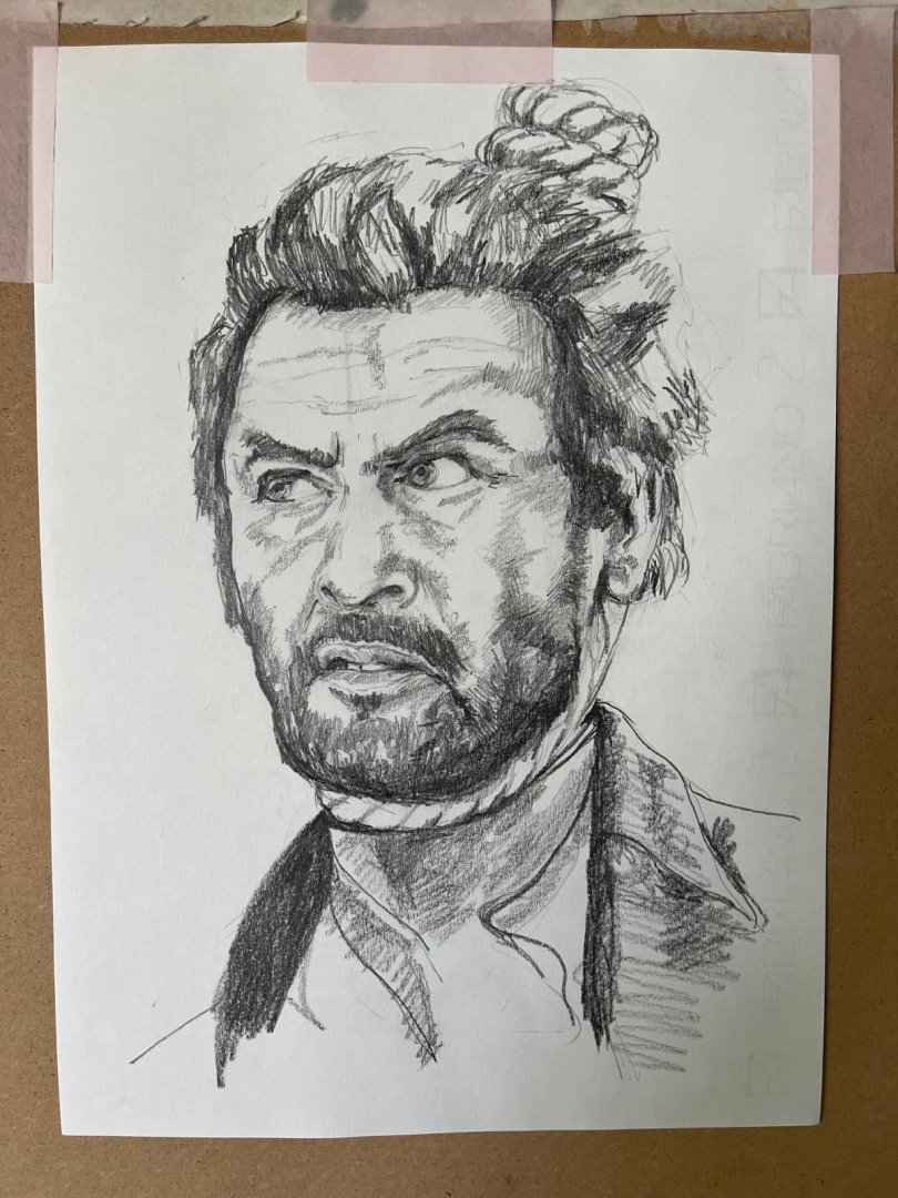
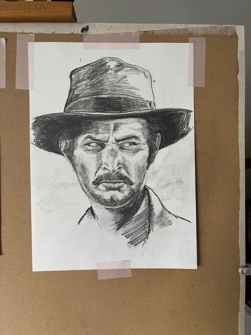
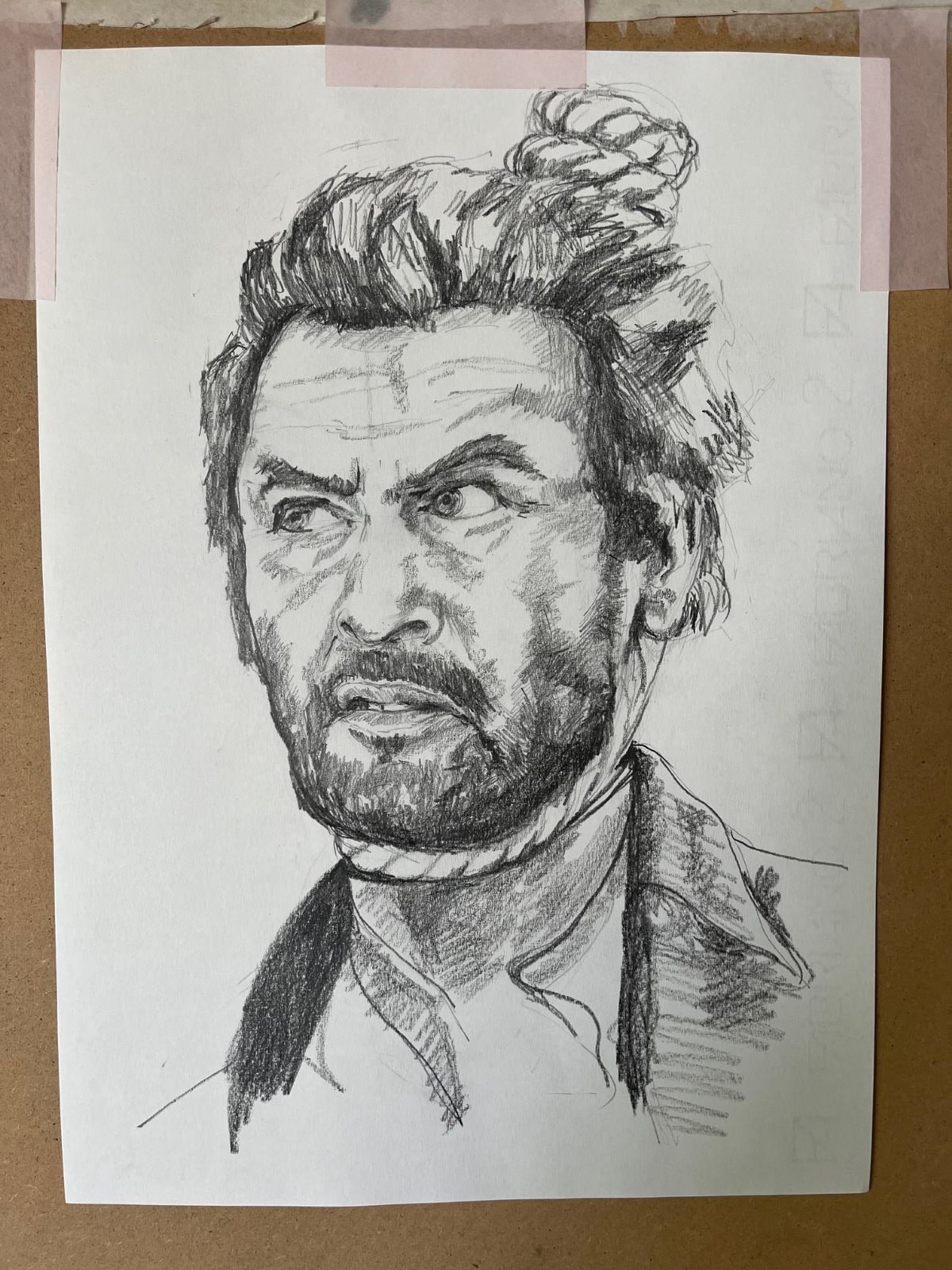
- with my retirement, I resumed an old hobby of mine which is drawing and painting, see below;
- I am going to drive a long trip down to Italy to visit roots and that will keep me away from my hobby desk for several weeks.
About the Mosquito, the installation of the Squadron vac-formed canopy is concluded and the result is quite ok, I will show you that as soon as I will have some progress, when I am back.
About the other hobby, let me post here two exercises of mine that perhaps should please at least Chris, @ccoyle, seen the quote he inserted in the footer of his signature. These are drawings made by pencil and that I copied from pictures of the actors that I downloaded from internet.
Sorry for the digression,
Arrivederci,
Dan
-
15 hours ago, gsdpic said:
The reflections are just from sitting the model on a 8" x 12" piece of white or black glossy acrylic that I bought online specifically for that purpose.
You gave me an idea to copy.
I second the others, great model and beautiful photography.
Cheers,
Dan
-
Everything looks so believable! Great modeling!
Cheers,
Dan
- Egilman, Old Collingwood, mtaylor and 4 others
-
7
-
Hi,
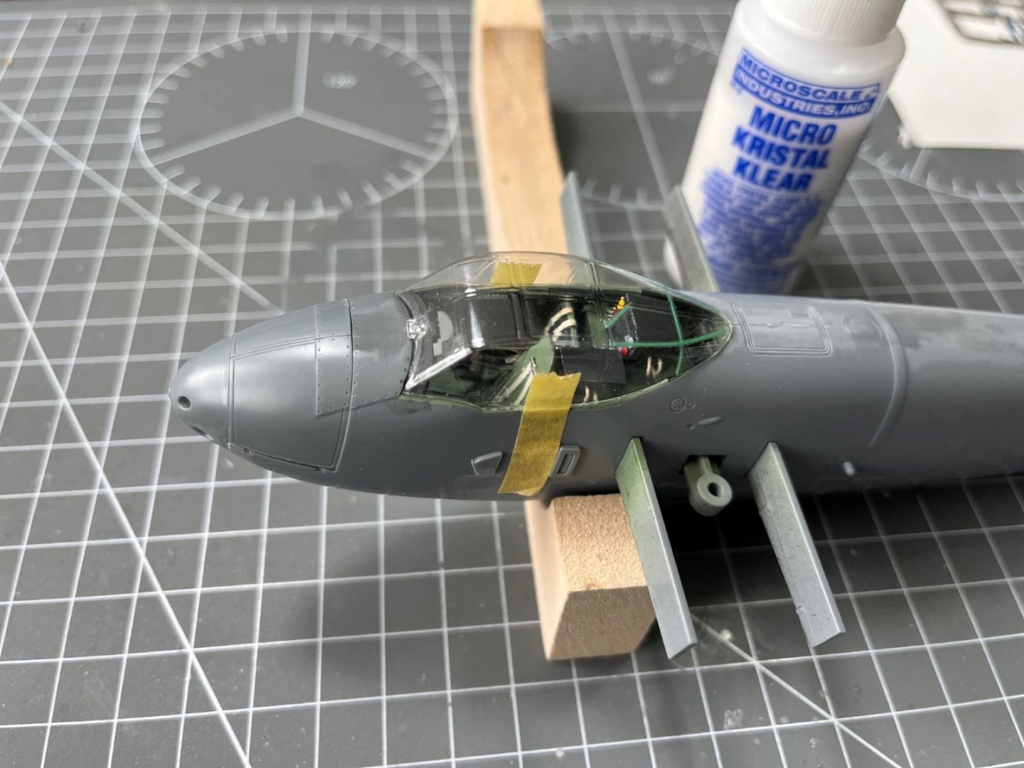
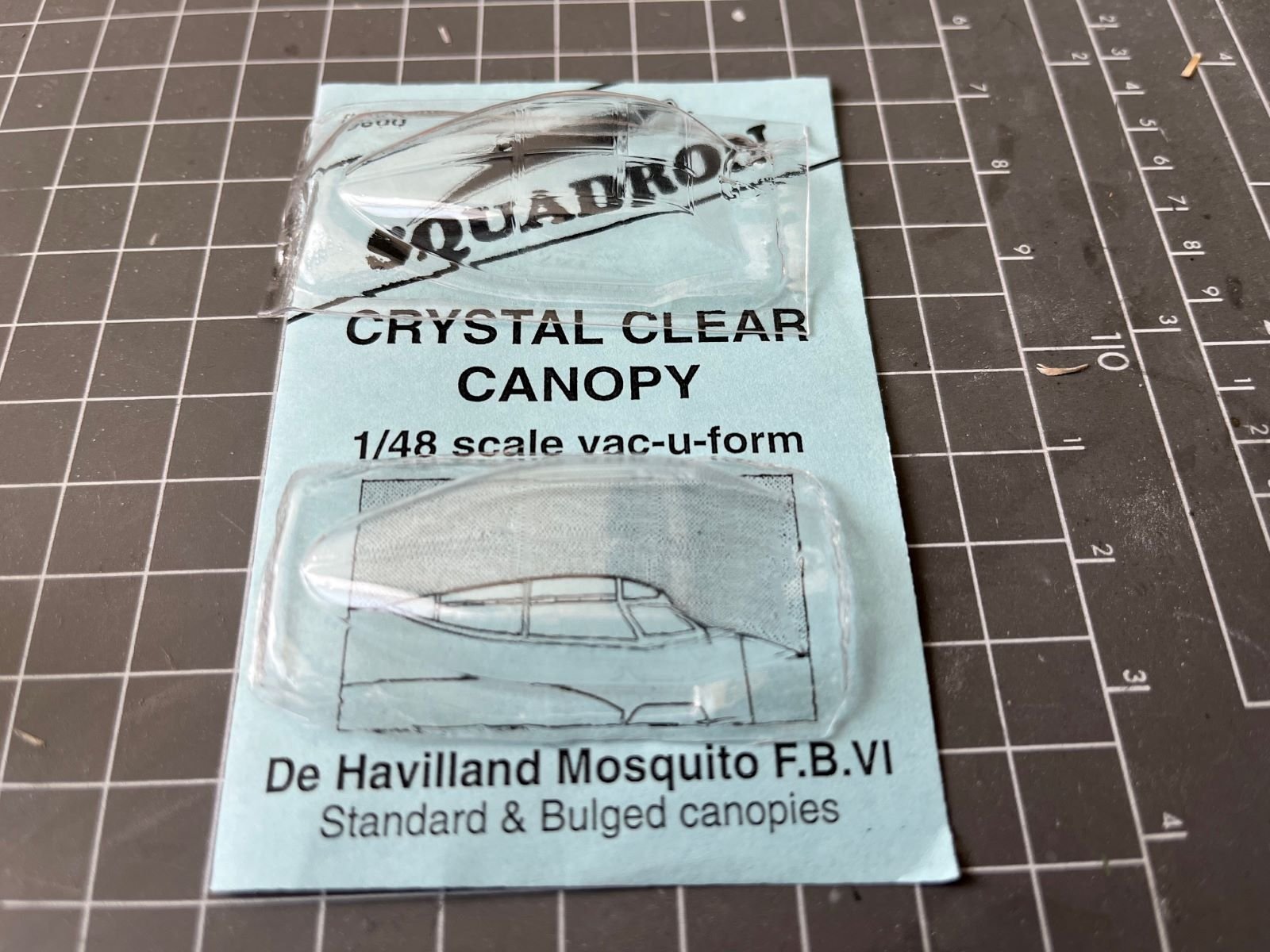
this post is dedicated to a problem that I had once I mated the fuselage halves and wanted to install the canopy included in the kit. Actually, the canopy of the kit is very well made with a very clear plastic, but unfortunately it was found accidentally separated from its tree. Consequently, the plastic in the vicinity of the gate was torn off and stress cracked in the bulk of the part as shown below:

The depth of the of the frame at this location is very narrow and once painted it is not enough to hide the offended area. After some attempts to sand and polish the defect, where instead of improving I worsened it, I decided that the canopy had to be binned and replaced. After a search on the web, I bought two vacuum-formed canopies produced by Squadron.
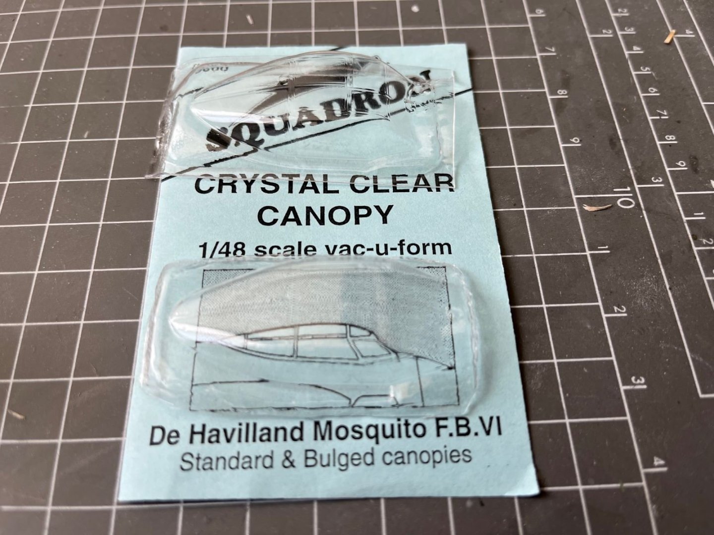
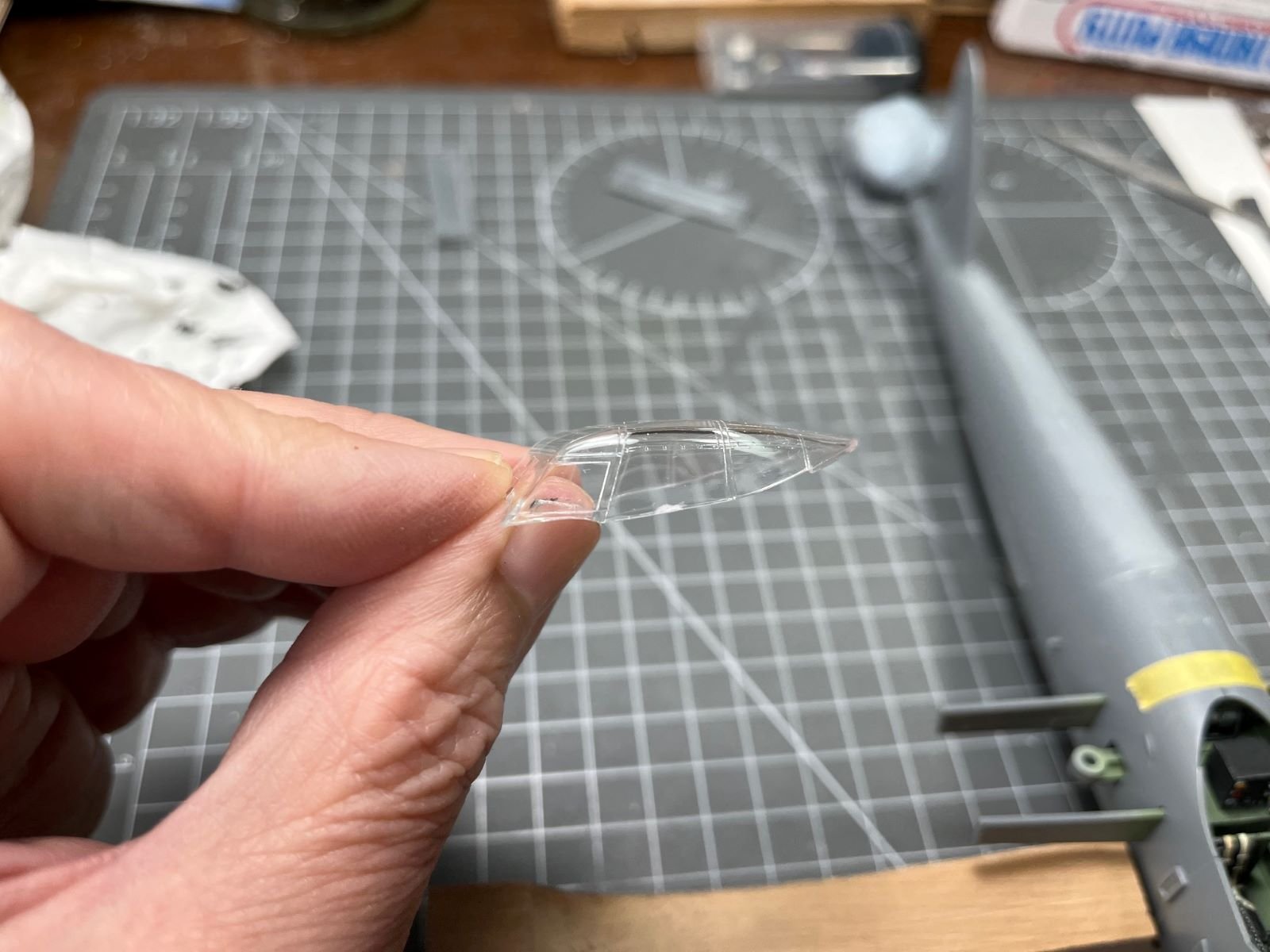
I must say that I never used these types of canopies and I was uncertain about their quality. The bag contains a blister with two canopies, but only one of them is usable for the model I want to build (i.e. the standard type).
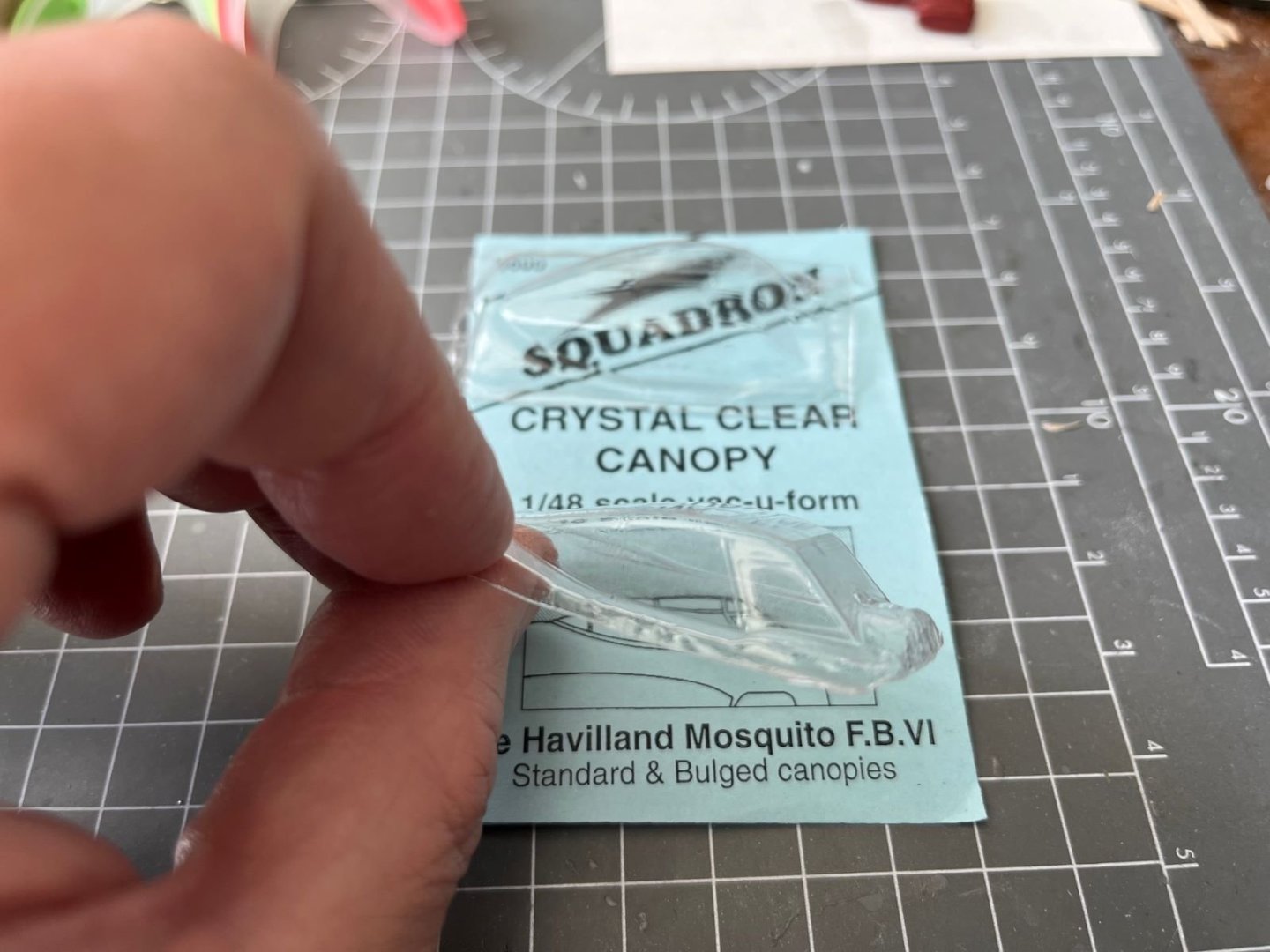
My doubts were associated with the very thin material used and with the necessity of precisely separating the canopy part from the rest of the blister. However, according to some articles, these canopies with their thin thickness are supposed to be even better than the original kit parts. For cutting, as prescribed by Squadron, I used a fresh X-acto blade making multiple passes with minimal pressure while the canopy was supported by a blu-tak plug pressed inside it. I first practiced on the bulged canopy before proceeding with the good one. At the end, the cutting and subsequent trimming fortunately turned out to be quite precise:
 Next, the gluing operation followed. According to Squadron and to most of the articles that I read, the most suitable glue to be used is the Micro Kristal Klear. The glue had to be thinned with water to decrease its viscosity and allow it to penetrate by capillarity in the gaps between the canopy and the sills:
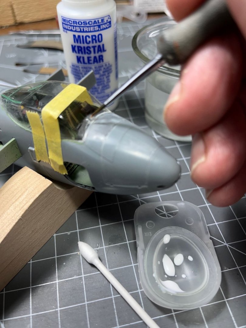
I brushed the thinned glue along the gap cleaning the excess with a wet pointed cotton swab. Because the thinned glue shrinks a lot when cured, this process has to be repeated as many times as necessary to satisfactorily fill the gap and obtain a fairly strong bond. So far it is going fine, but I will be able to see the quality of the result only when I will brush some paint over the joint.
That's all for now,
best regards.
Dan
-
44 minutes ago, Egilman said:
Structural strength is maintained by stressing the wire spokes in tension, Adjusting a wire spoked wheel is just about a lost art today...
Indeed, actually, on top of what I said (I simplified a bit the story), as you said, all the spokes must be pre-stressed in tension (the lost art), so the ones on top increase cyclically their tension load and the ones on the bottom decrease it without becoming compressed and so avoiding buckling. Torque (of the engine or the brakes) is transmitted from the hub to the rim thanks to the eccentric positioning of the spokes (if the spokes passed through the axle, no torque could be transmitted). I stop here.
Best regards,
Dan
-
It is a beautiful model, everything looks so believable, the metallic parts are great.
In connection with the spoked wheel, let me have a little digression that might be amusing for some. When I a was a fresh graduated engineer, during a job interview, I was asked to discuss the loading capabilities of thin rod loaded in axial compression. Clearly as intuition said and as confirmed by the maths behind, long and thin rods could not take meaningful loads when the radius is very, very smaller than the length. The next question was: "then, how a spoked wheel of a bike can carry your weight?". After a bit of thinking, I concluded that the weight is carried by the upper spokes that are loaded in tension, so, when riding a bike you are 'hanging' on the upper spokes and nor supported by the lower ones. This was a surprising fact for me that I never realized before. By the way, the interview was successful.
Sorry for my digression,
best regards,
Dan
- CDW, shipman, Old Collingwood and 6 others
-
9
-
-
The engines look great.
Dan
-
-
What a sharp looking plane you have, Dave! Very well executed, the paint finish is spotless and it looks wonderful with its vivid livery.
Congrats,
Dan
-
-
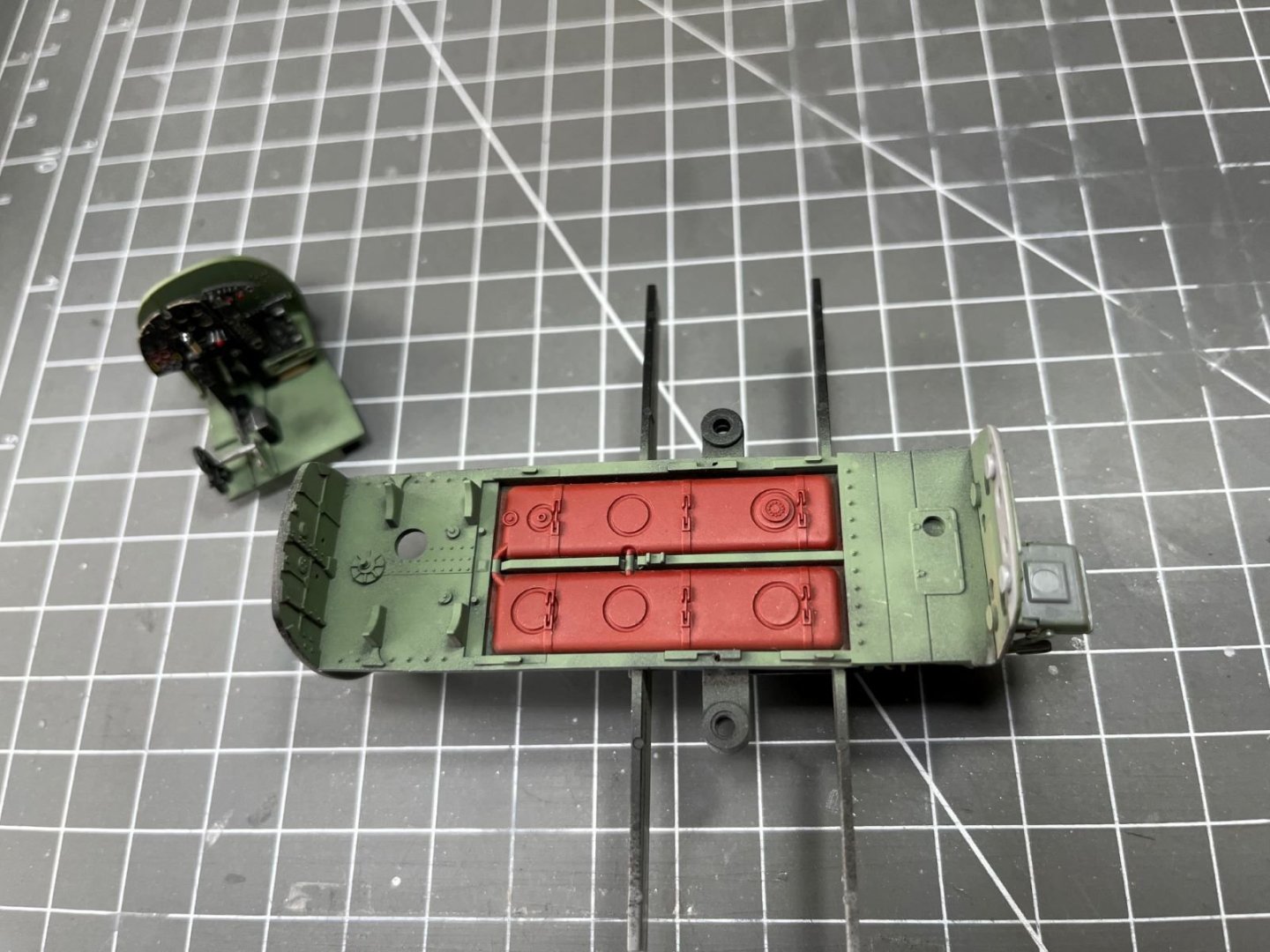
Dear all,
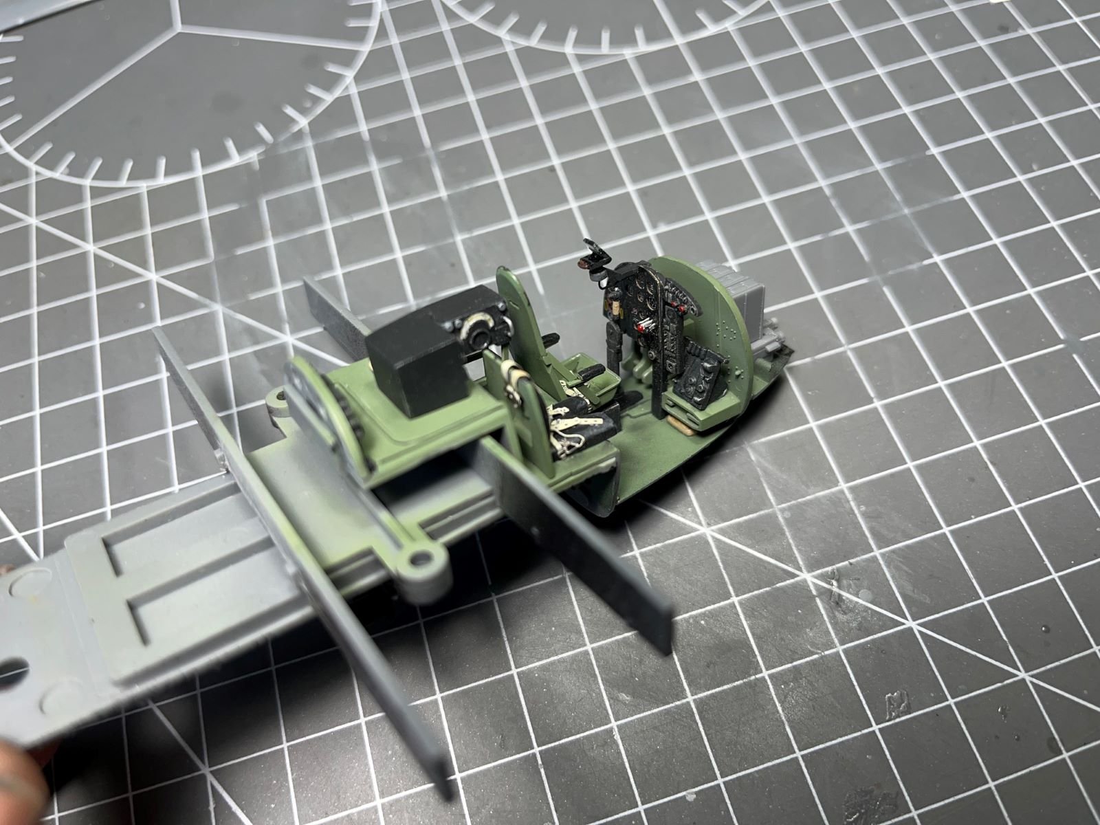
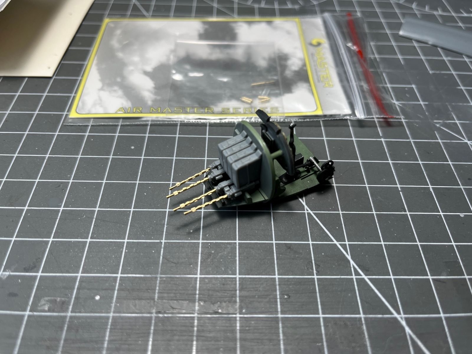
these are last steps with the fuselage interior. I added the gunsight to the cockpit and these are its last images before enclosing it in the fuselage:

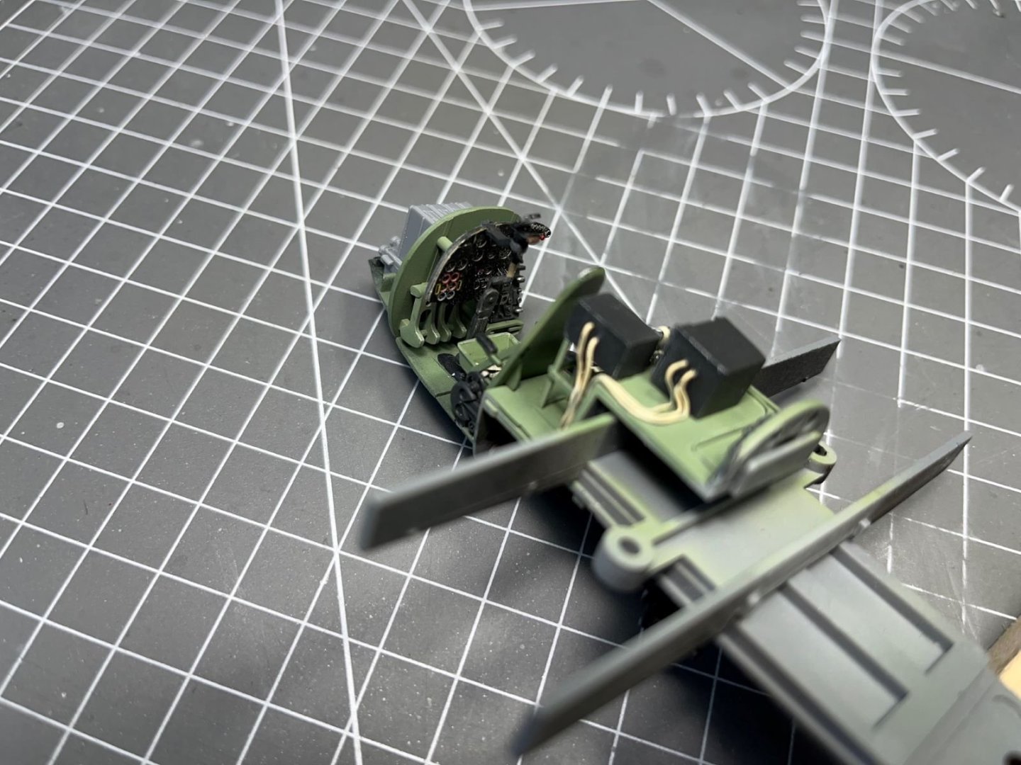
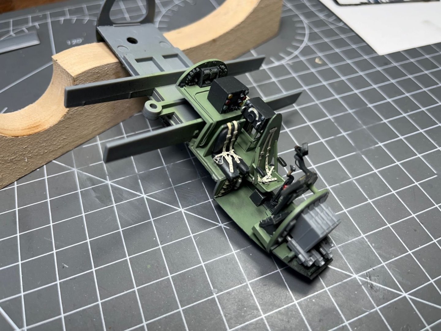
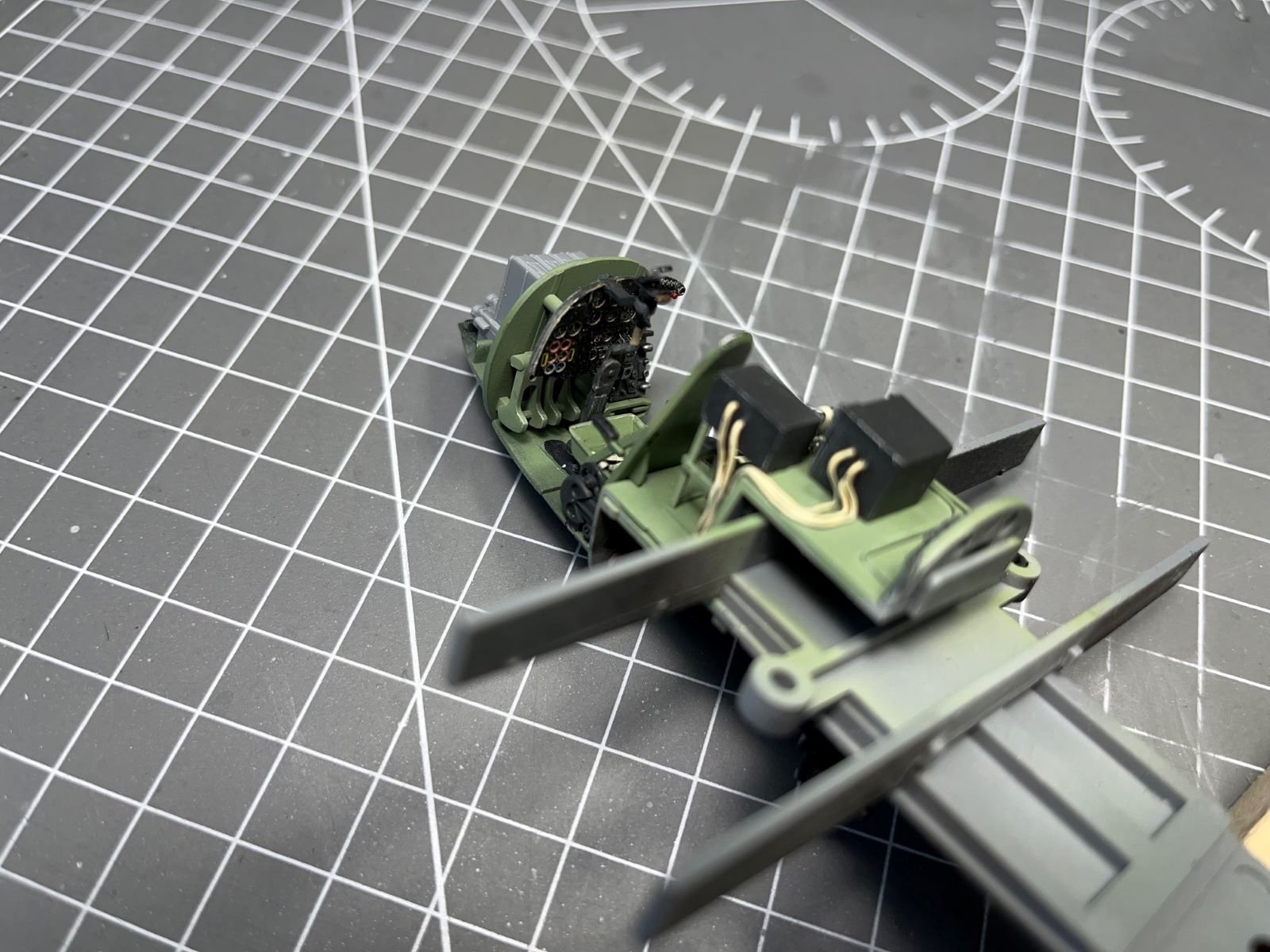
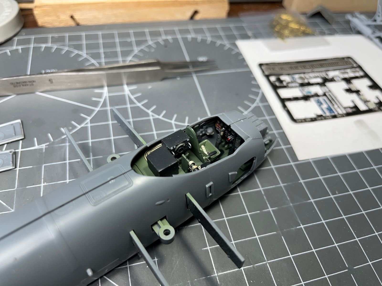
The fuselage interior was painted black and then mottled with the interior green. The cockpit posed with the port half:
And with the starboard half:

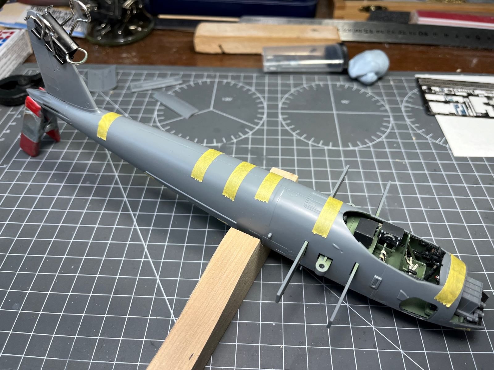
The first important milestone, the fuselage is now buttoned up:

With few additions, the parts of the kit allowed to fabricate a nice and detailed cockpit. The last piece of equipment glued on the edge of the coaming:
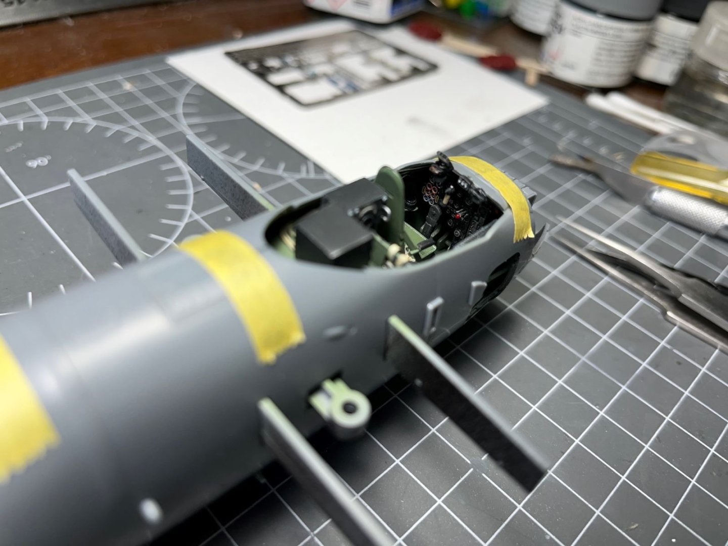
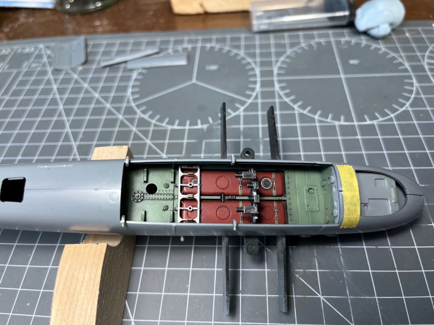
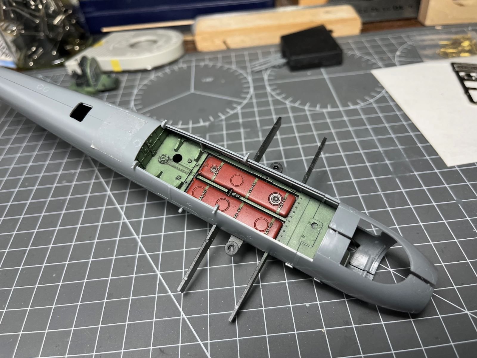
The bomb bay with the false breeches of the four cannons now looks like this:
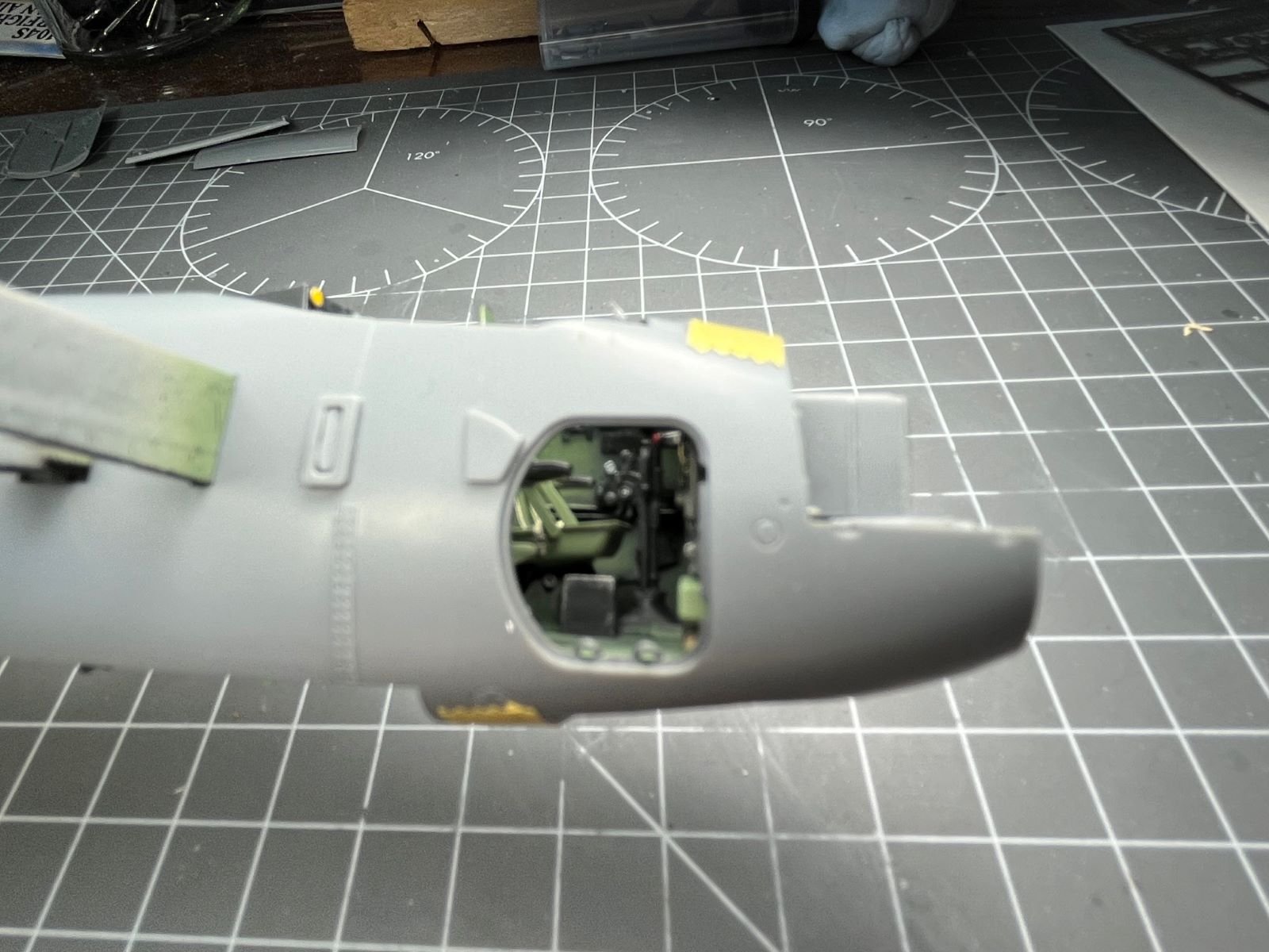
For @Old Collingwood, I tried to take a picture of the cockpit seen through the open hatch, but it is not in focus:

That's all for now, thanks for following,
Dan
-
19 hours ago, Old Collingwood said:
Some lovely progress there, will you be leaving the entrance hatch open to allow some views into the cockpit?
Thank you OC! Yes I am planning to pose the hatch open, I saw that you can peek inside and appreciate some nice details from there.
Dan
-
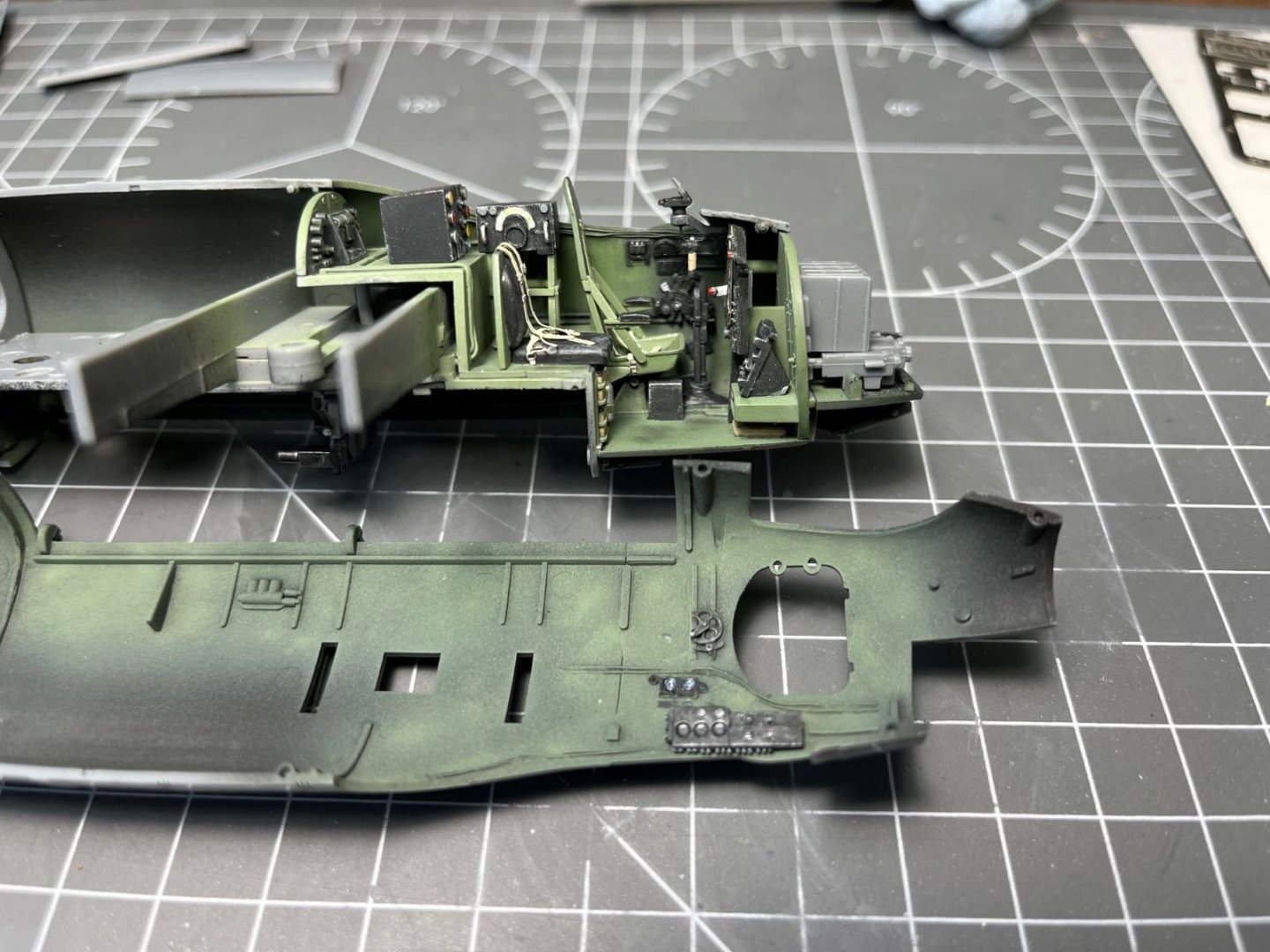
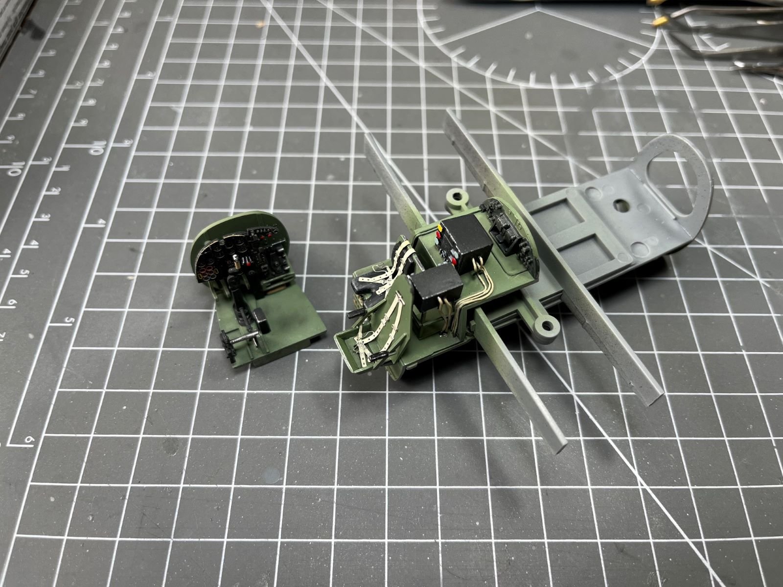
Dear all,
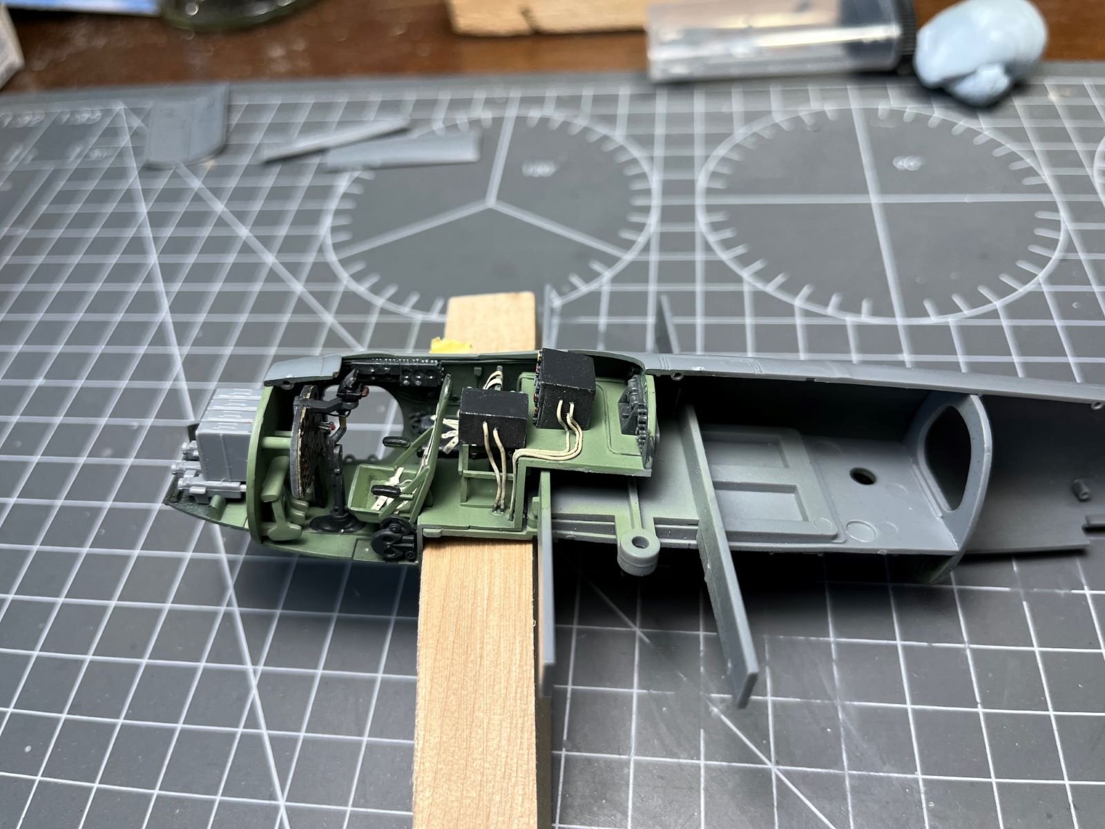
a short update with nothing exciting, but I needed to complete some necessary activities in preparation for closing the fuselage halves. One very tedious task was to address the many ejector pin marks on the fuselage inner sides. Then, the interior was furnished and some 'fantasy' cabling was added:
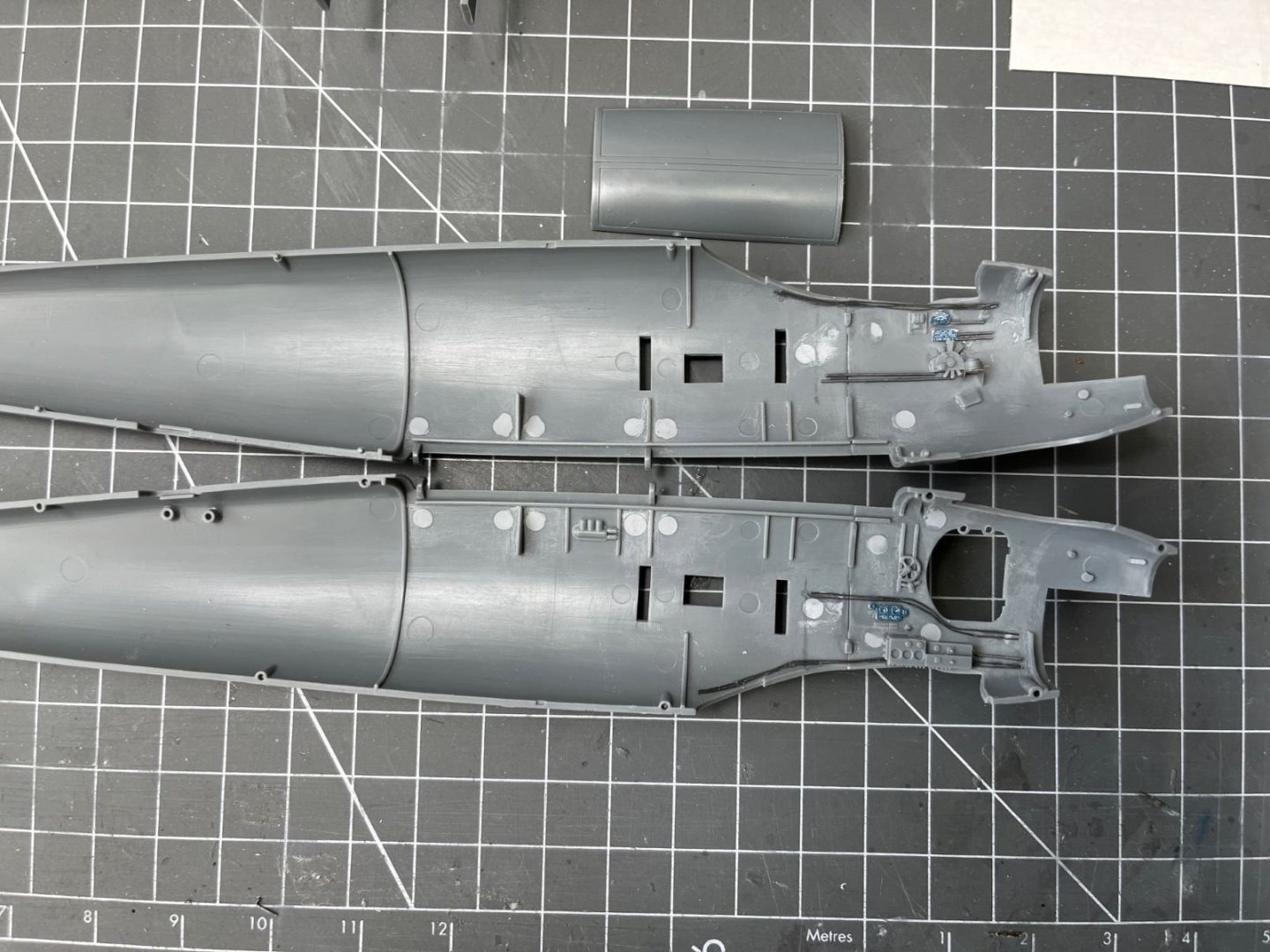
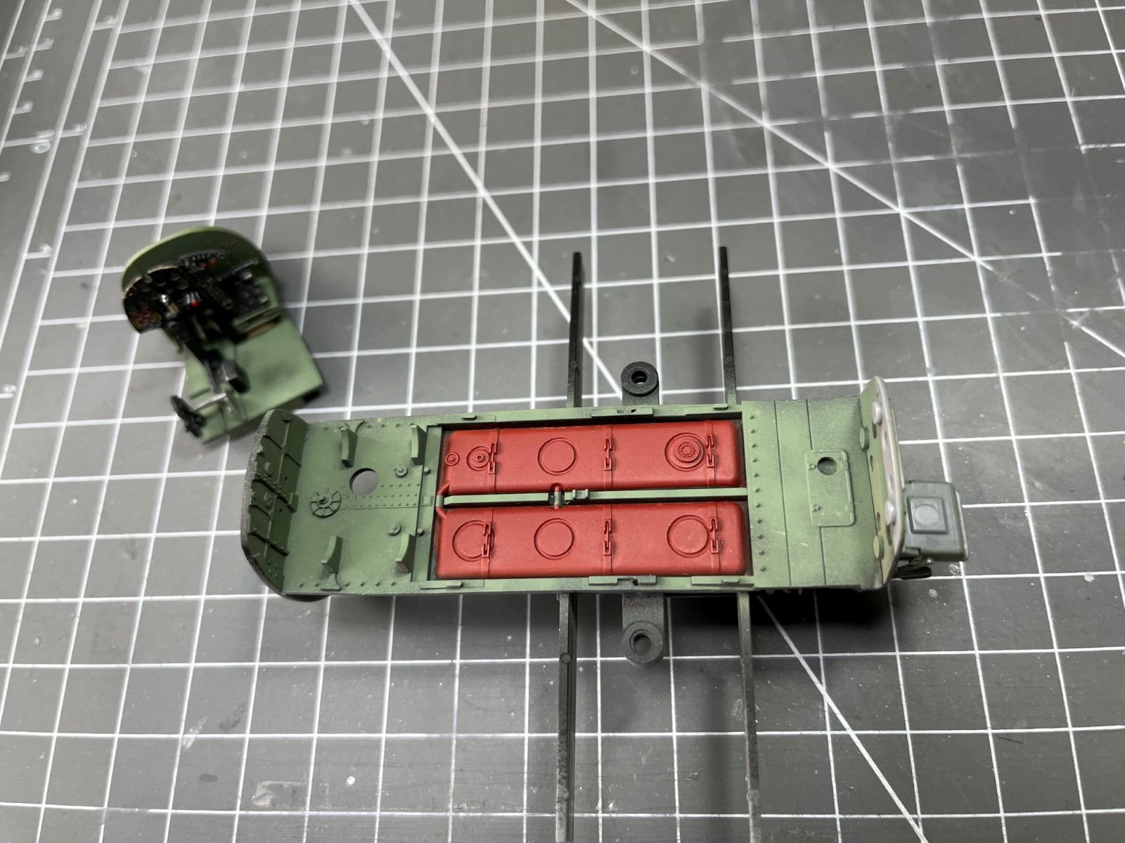
The two halves are now ready to receive some black paint before the interior green. Meanwhile, I finished to weather the bomb bay with the application of some black and brown Tamiya panel liner:
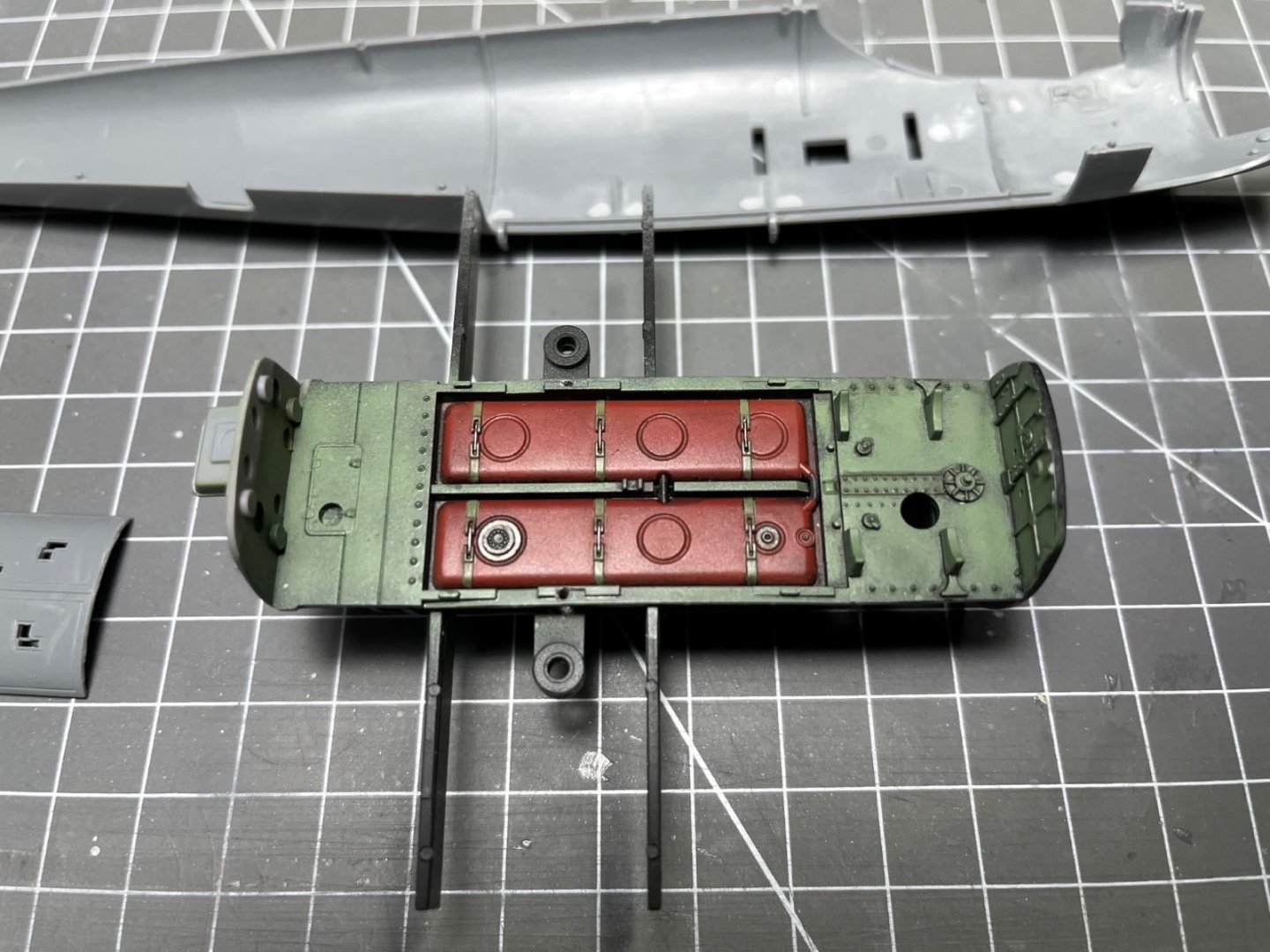
It turned out quite OK when inside the fuselage, although I must say that little of it will be seen because it will be covered by the structures that will held the bombs and half of it will be hidden by the doors of the cannons bay:

In the nose, I am replacing the Browning machine guns muzzles with the very nice Master brass additions:

I will glue them in place later on, probably after the application of the camouflage. I am not going to detail the gun bay and probably I will close this compartment after having glued the muzzle definitively in place. Finally, I am posting a picture of the completed cockpit tested inside the fuselage to show how much of it will be visible:

That is all for now, thanks for following,
Dan
- CDW, Egilman, Haliburton and 13 others
-
16
-
@mtaylor, @Old Collingwood, I also have interpreted the plate where the backrest of the navigator is located as an armored plate. I even made some chipping on the edge of it. However, even assuming so, the head of the navigator was not protected. But I have seen such an arrangement also when I built the interior of the Beaufighter where the pilot seat backrest stopped at the shoulders height.
Cheers,
Dan
- Dave_E, Canute, king derelict and 4 others
-
7
-
-
-
-
Great build, Chris. I like the 'curvy' lines of this old fighter.
Well done,
Dan
- Jack12477, Keith Black, Dave_E and 5 others
-
8
-
4 hours ago, king derelict said:
The cockpit details look great.
Thanks Alan! Glad that you like it.
3 hours ago, realworkingsailor said:Looks great Dan! I’m glad the Yahu IP worked for you!
Thanks Andy! Yes, the Yahu IP was a great addition. After you mentioned it, I got a light bulb switched on.
1 hour ago, Old Collingwood said:Lovely work, the cockpit area was my fave part when I built the Revell version some years back.
Thanks OC. I also liked this one, with few additions I easily busied it up. However, the Mosquito has a closed canopy, but I am confident that something will be anyway visible.
Cheers,
Dan
- mtaylor, Old Collingwood, Egilman and 6 others
-
9
-
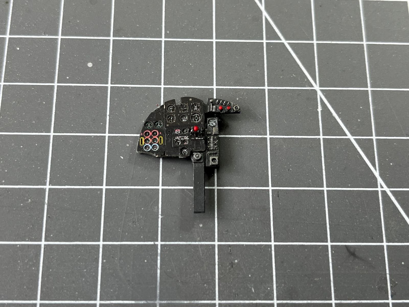
Hi,
I went on with the cockpit parts. I eventually received the super nice Yahu replacement for the instrument panel which is shown here glued to the other kit parts:
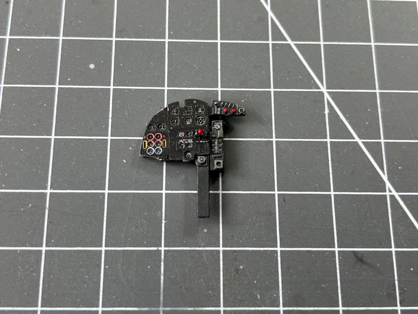
I have added three prominent control levers in the center of the panel made of thin aluminum foil to complete the appearance of the IP. These are the cockpit parts that are now basically completed:
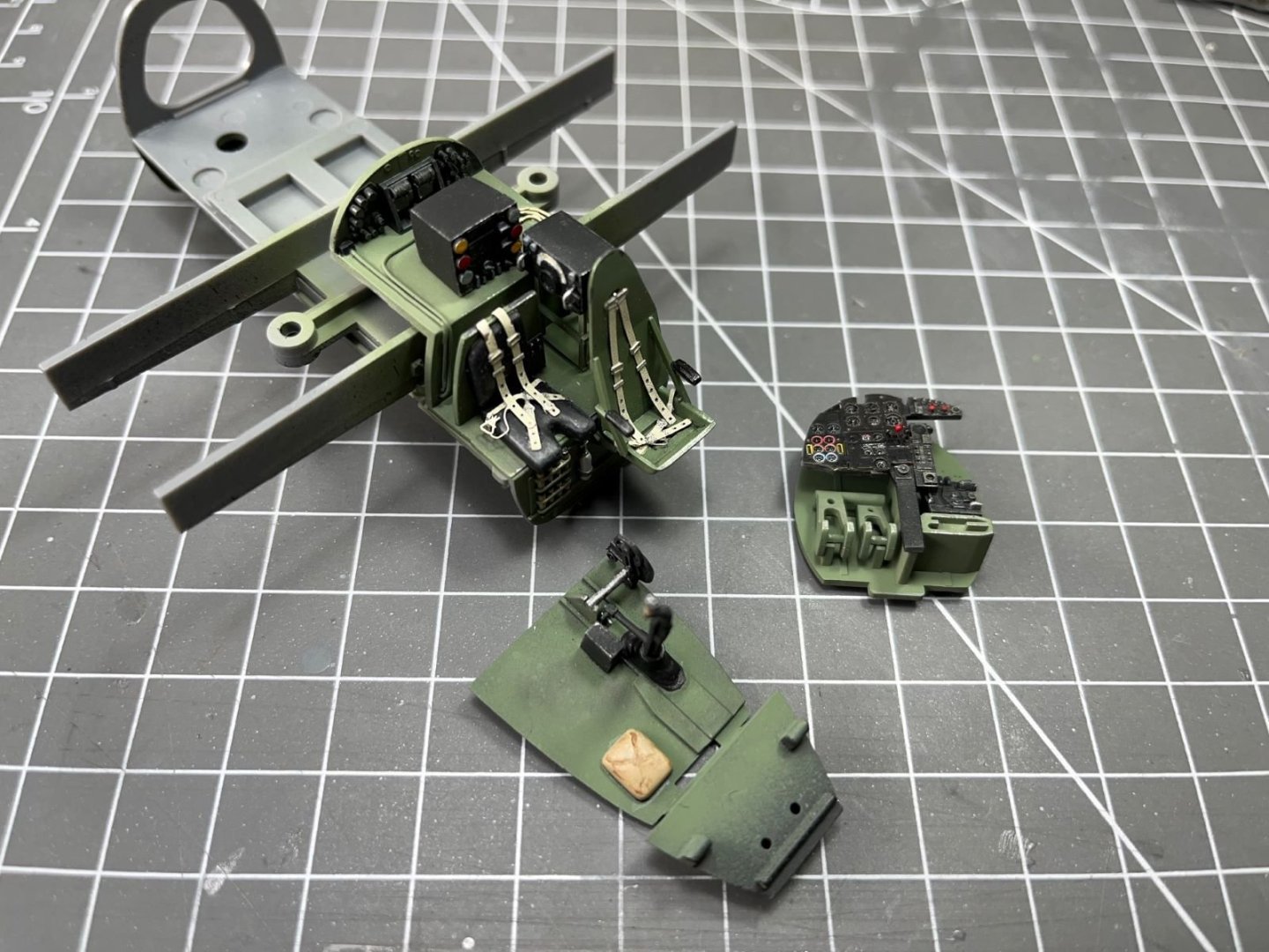
Differently from the instrument panel which was a disappointment, the Eduard seat belts worked fine and added a nice level of details to the kit seats. These are the same parts seen from another angle:
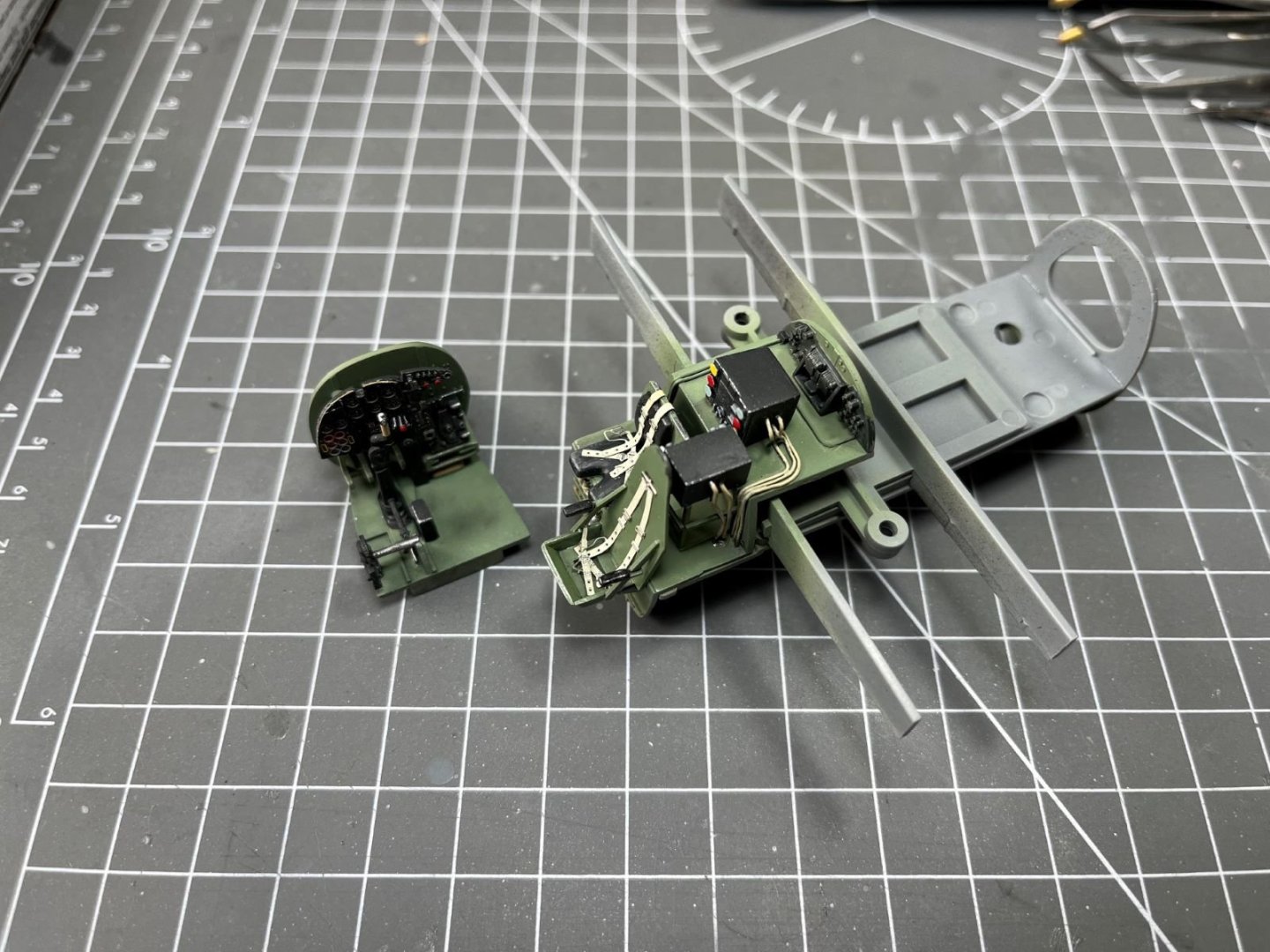
This time, I am going to depict a used aircraft, so I added some grime and dirt by brushing on some pastel powder. Now the parts are basically ready to be assembled, but before I will spray a mist of matt clear to uniform the finishes and mute the glint of metallic parts. On the underside of the cockpit, we have the ceiling of the bomb bay which I also started to color. I first sprayed a black primer followed by a light coat of colors that let the black to be seen through (although not very visible in the picture):
I will finish the bay by adding some more weathering effects to it. Presently, I am preparing the fuselage halves that need to have some of their annoying extractor pin marks to be addressed.
That is all for now, thanks for following,
Dan
- Rik Thistle, gsdpic, Ryland Craze and 16 others
-
19
-
Canopy turned out excellent. About the spinner and the blades, I should not feel compelled to paint them with the exact same color. They were painted with different paints (propeller blades have usually a special paint) and wear under different conditions.
Cheers,
Dan
- ccoyle, mtaylor, Old Collingwood and 4 others
-
7
-
5 minutes ago, realworkingsailor said:
If you just want to replace the IP, try Yahu models.
Thanks, just found it here in the Netherlands (1/48 scale) at less than 5 euro. I just ordered it, together with an 'in action' publication about the Mosquito (you know, just to achieve an amount worthy of the order).
Cheers,
Dan
- Old Collingwood, Dave_E, mtaylor and 4 others
-
7


DeHavilland Mosquito FB Mk VI by Danstream - Tamiya - 1/48 scale - PLASTIC
in Non-ship/categorised builds
Posted
Yes, I loved these western movies, they were packed with these cold-humor lines and situations. I don't know whether they would be considered acceptable nowadays. Anyway I liked them a lot. Great actors, great scripts, great director and above all memorable music. If you like it, tries the following:
Cheers,
Dan