BANYAN
-
Posts
5,965 -
Joined
-
Last visited
Content Type
Profiles
Forums
Gallery
Events
Everything posted by BANYAN
-

HMCSS Victoria 1855 by BANYAN - 1:72
BANYAN replied to BANYAN's topic in - Build logs for subjects built 1851 - 1900
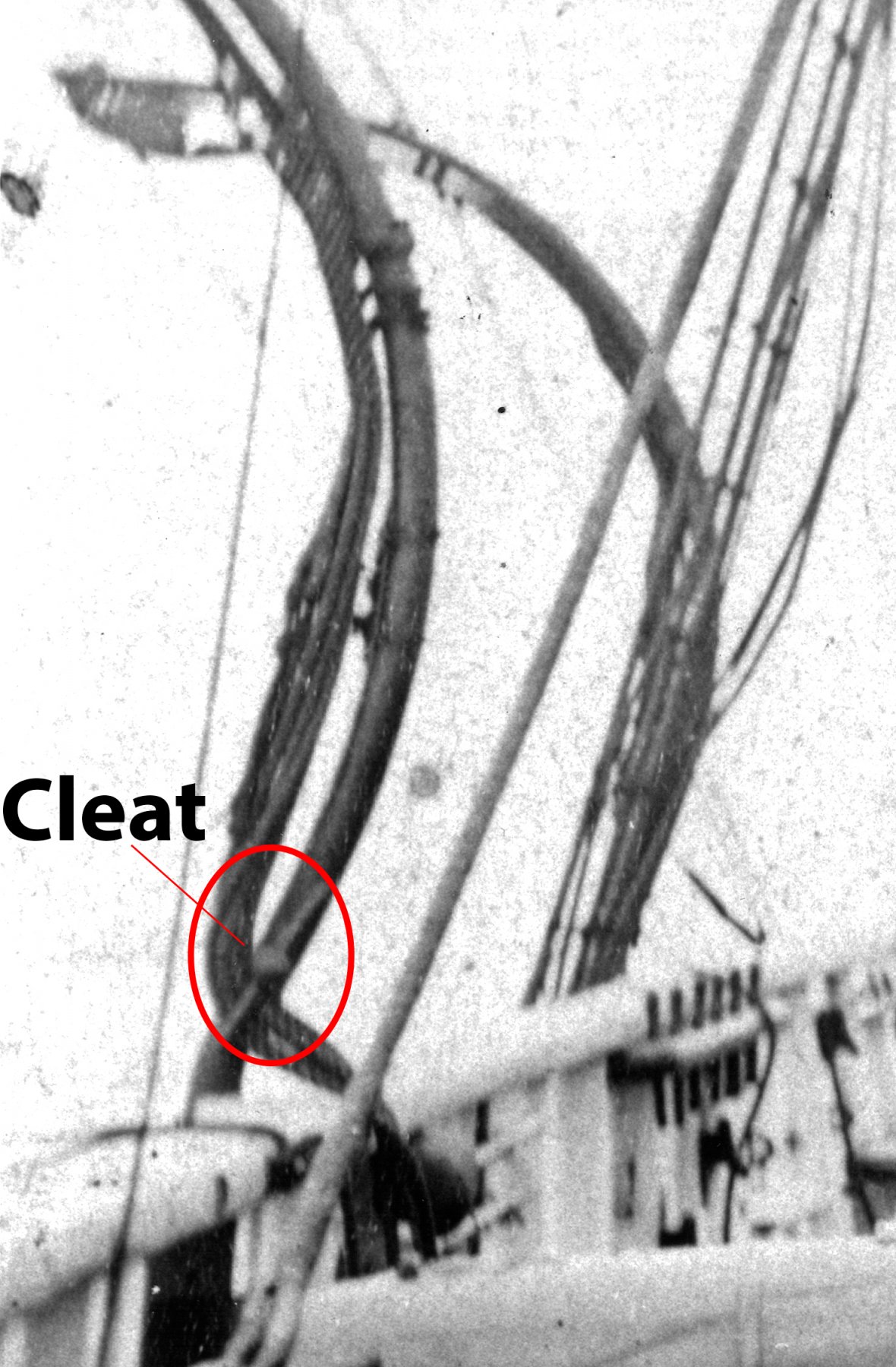
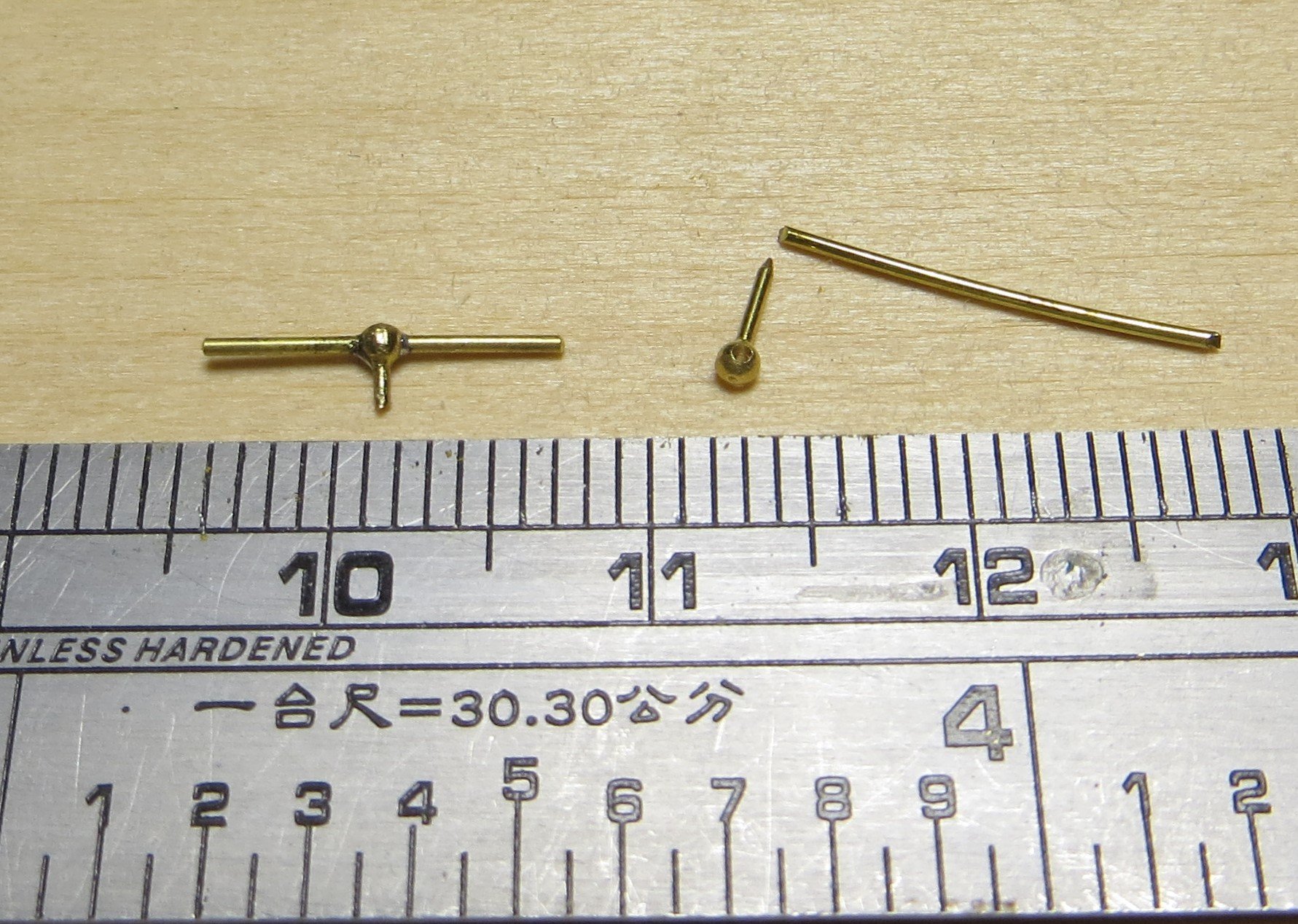
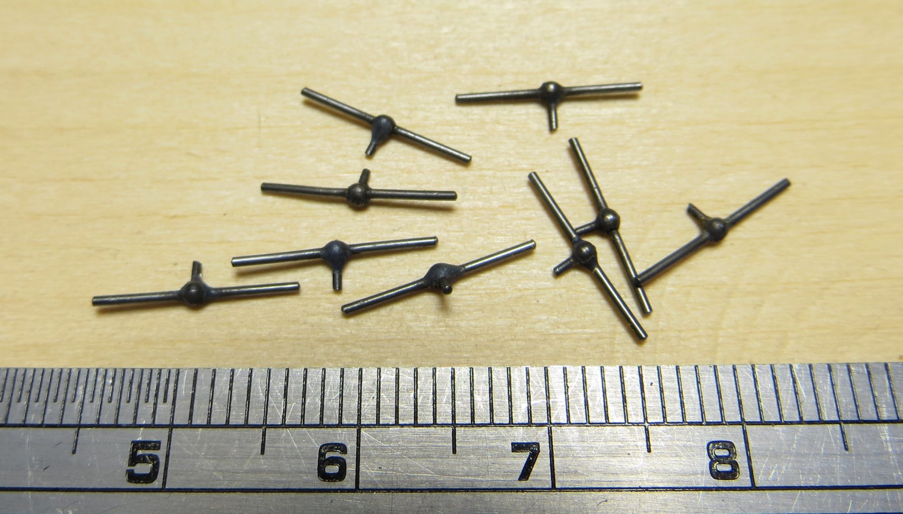
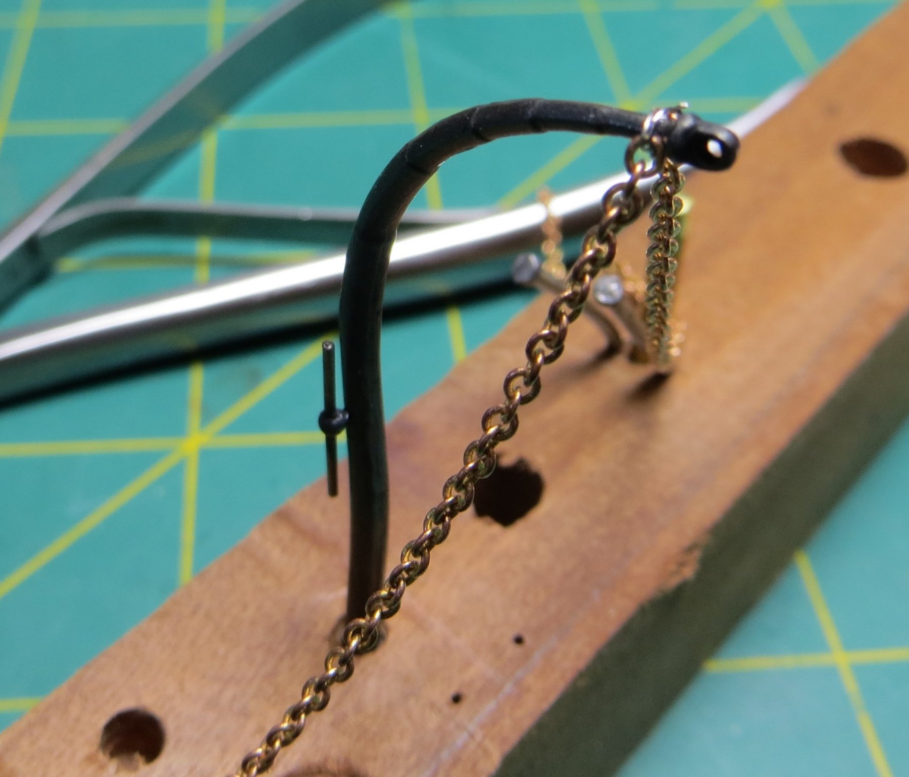
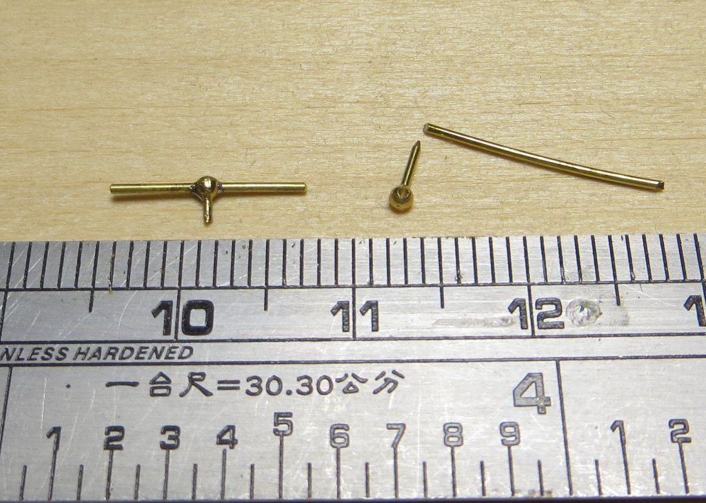
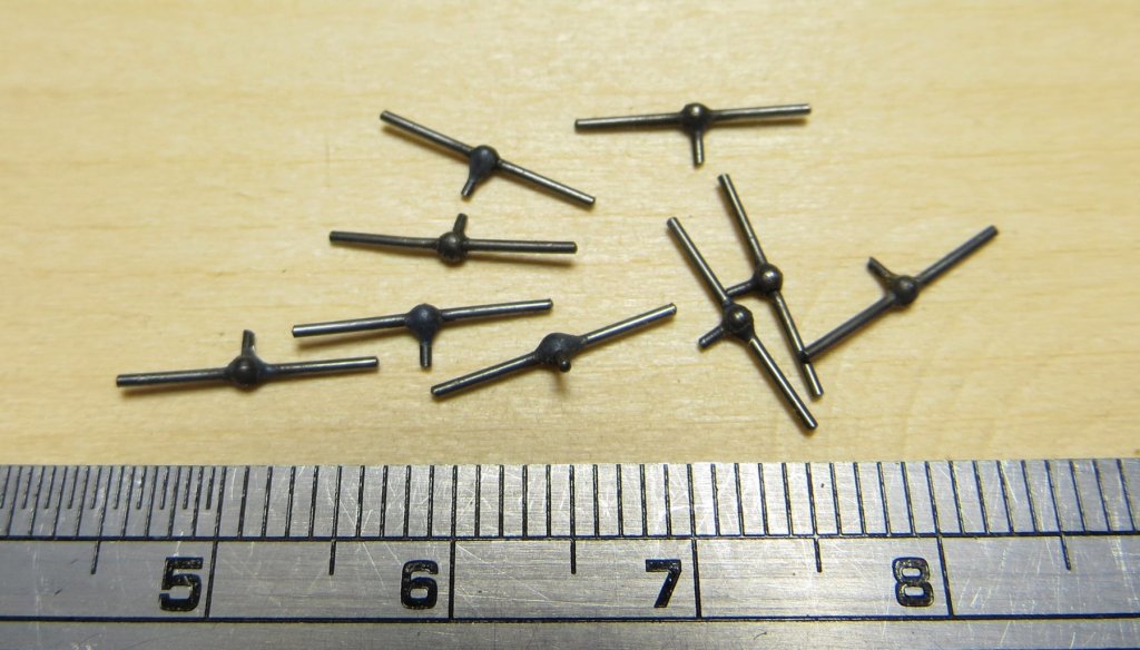
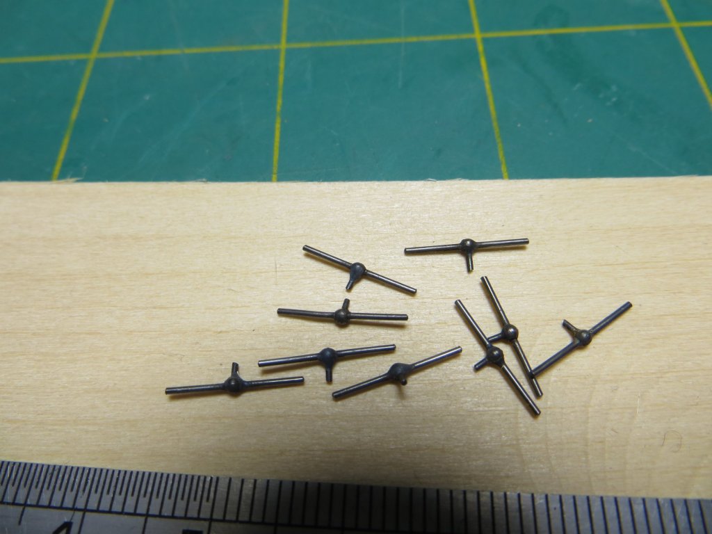
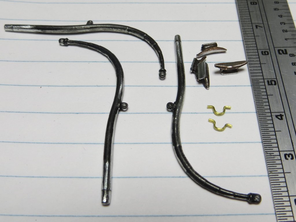
i all, I have been experimenting to see how to complete the davits I discussed earlier. The picture I have of the Officers and some crew on quarterdeck, shows te davits in the background. Note the shape of the davit cleat. I decided not to go with the modified shroud cleats and made some new cleats for which I have shown some of the process below. The cleats have still to be polished to remove some more of the oxidation but I think they have come up OK? One is shown loosly fitted (not glued yet) on a davit arm along with an experiment for fitting the stay and brace chains to the davit head. this was done with some very fine nichrome wire which I think will do; just need to work out how to fix it in place now Note the chain is too much out of scale but is the smallest I have now (12 links per inch) I think I need about 24 links per inch to get the scale right.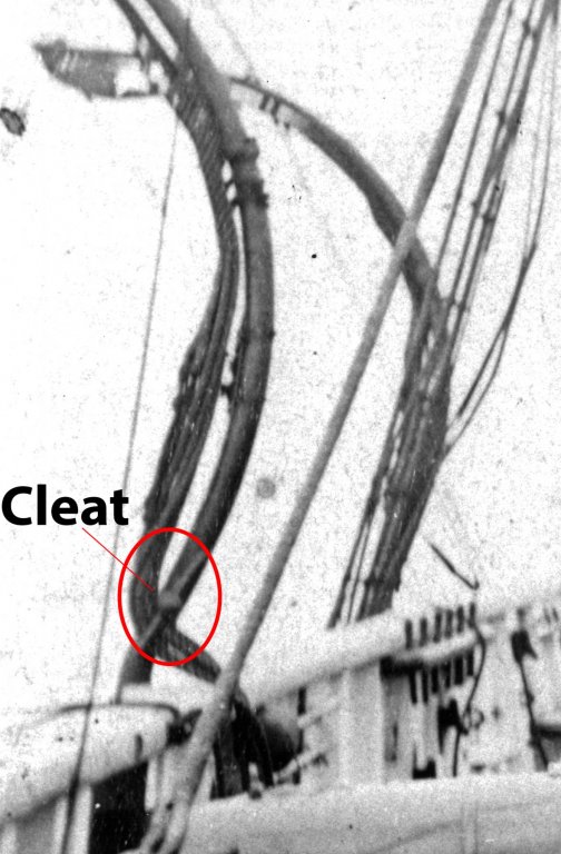

- 1,021 replies
-
- 12
-

-
- gun dispatch vessel
- victoria
- (and 2 more)
-
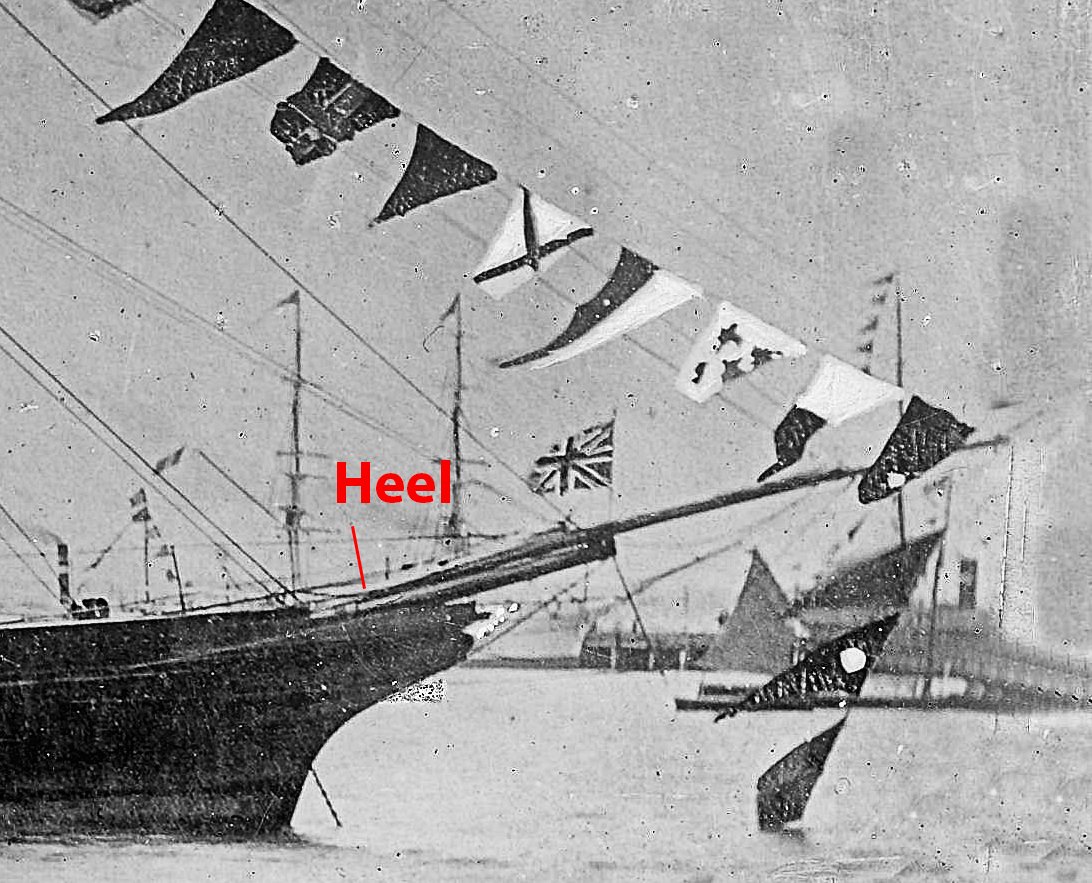
Seriously nice work Ed, as Rob states the idea of the plate through the martingale is a great tip. Rob, my Victoria (1855) also has the heel finishing in approximately this position, but I think in my case there is a heel chock at the base. The following is a much cropped extract from a photo of the ship I have and although grainy seems to confirm this - but open to interpretation. According to Underhill, this chock could extend back to the stem, or finish short (ramping/slanting backwards to the bow. cheers Pat

- 3,618 replies
-
- 5
-
-
- young america
- clipper
- (and 1 more)
-
Coming along very nicely Danny; if you hadn't pointed out the shorter arms due to initial misplacement, i for one would not have noticed cheers Pat
- 295 replies
-
- 4
-
-
- amatsukaze
- halinski
- (and 2 more)
-
Hi Greg, those could have been awning stanchions? or even damage control shoring also. Coming along well, more great detail on this one. You make me feel positively like a snail with my build cheers Pat
-
HMCSS Victoria 1855 by BANYAN - 1:72
BANYAN replied to BANYAN's topic in - Build logs for subjects built 1851 - 1900
Thanks for looking in Ed; I had better pick up my game a bit now. cheers Pat- 1,021 replies
-
- 1
-
-
- gun dispatch vessel
- victoria
- (and 2 more)
-
Slow build or not John, I am sure it will be another interesting build to watch cheers Pat
-
Hi Greg, would the trick of adding baking soda or talc to the thin CA work? I have seen card modellers use this technique to get a real tough bond. cheers Pat
-
Very nice clean work Ed; great progress on that spar. cheers Pat
- 3,618 replies
-
- 3
-
-
- young america
- clipper
- (and 1 more)
-
HMCSS Victoria 1855 by BANYAN - 1:72
BANYAN replied to BANYAN's topic in - Build logs for subjects built 1851 - 1900
Thanks Dave. cheers Pat- 1,021 replies
-
- 1
-
-
- gun dispatch vessel
- victoria
- (and 2 more)
-
A simple and very effective jig; a well thought out solution Russ. Looks good. cheers Pat
- 420 replies
-
- 4
-
-
- captain roy
- lugger
- (and 2 more)
-
Hi Danny, in my day they were just called rails and constructed exactly the same as the inboard hand rails. Their purpose was several: 1. Tie rail for the canvas/vinyl weather cover over the top of the funnel when the boilers were shut down. 2. Grab / safety rail when working/checking the top of the funnel 3. Tie rail for the bosun chairs or staging used when painting the funnel (safety lines were not secured to the same rail for obvious reasons). cheers Pat
- 295 replies
-
- 4
-
-
- amatsukaze
- halinski
- (and 2 more)
-
I go away for a couple of days and see what you do Greg! You don't muck around between builds do you? Seems you have a real affinity for the WWII Japanese ships (or are you just trying to use up the remaining PE from previous builds ) Are you planning on this one being a real work horse also? Look forward to this build, it looks an interesting ship. cheers Pat
-
HMCSS Victoria 1855 by BANYAN - 1:72
BANYAN replied to BANYAN's topic in - Build logs for subjects built 1851 - 1900
Hi Carl and Wefalck, thanks for looking in and the kind comments. Wefalck, I pursued the white metal ones purely as a time saver. Between trying to research, draw plans and build this model time is a premium. I was able to get some davits of about the right size; all I had to do was remove a couple of fittings and bend the arc into the vertical part (thumb and forefinger pressure). i had been tempted with brass but the tapering profile from base to davit head would be difficult to achieve. As to the swivelling head, I had thought on this but the evidence I have seems to put that about 10 years later than Victoria. Noting this was a time of 'flux' and that Victoria had the latest and greatest in most areas of construction, it is possible she may have had the swivelling head. That said though, the NMM models I have found with that type of feature, including the picture above, were all dated about 1865. Also looking at the photos of the ship, it would appear that they are a more traditional head with perhaps a swivelling block? The Contract did specify bronze bound block but did not state swivelling and is fairly explicit for most such equipment. I have gone for this configuration as it most closely resembles the davits shown in the photo. I think I will go with the fine wire option, and even contemplating a change to the cleats to better reflect the type shown in the photo (need to look closely) which are more like a rod through a ball head Thanks again for your feedback and helpful comments. cheers Pat- 1,021 replies
-
- 3
-
-
- gun dispatch vessel
- victoria
- (and 2 more)
-
HMCSS Victoria 1855 by BANYAN - 1:72
BANYAN replied to BANYAN's topic in - Build logs for subjects built 1851 - 1900
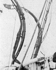
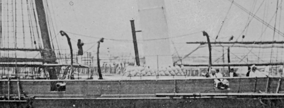
Hi again folks, As mentioned above, and with reference to the photo of the davits (last one), I have yet to add two eyes to the head of each davit and I am struggling to determine the best was to do this. These will be added such that there is an eye either side of the arm, perpendicular to the horizontal axis of the top of the davit head. These eyes were used to shackle the chain stays to. One stay between davit heads, and a fore/after stay on the respective davit that led to just under the cap rail of the bulwarks. The attached image is of a contemporary boat on davits model in the NMM (SLR1793) and shows what I need to achieve. The second photo shows the davits, as fitted to Victoria, from standing forward of and inboard of the after starboard davits, showing the inward curve, and that they were fitted outboard of the bulwark. The third photo is taken from a side on shot of the ship and clearly shows the configuration, including the chain stays. The loops you can see are the falls, neatly lashed back onto the davit arms. In the second photo you can also see the man-ropes lead back neatly inboard closest to the fore davit; this I will assume will also indicate/imply that the boat steps on the bulwarks were fitted arounf this point. The conundrum. If I drill the head of the davit (less than 1 mm), the davit would be too weak and snap. I will be using two part epoxy to add the large cleat (modified shroud cleat) so I could try to glue something, but sufficient glue to hold a sub-millimetric wire eye would look out of scale and probably be two weak to withstand fitting the chains. I can't solder the eyes in place as these are white metal and would disintegrate as soon as any heat got near them The only solution I can think of is to use some very fine wire passed through the end links of the two fine chain stays then wrap around the head and fix with a small dab of epoxy. Can anyone suggest a better way? cheers Pat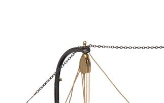
- 1,021 replies
-
- 7
-
-
- gun dispatch vessel
- victoria
- (and 2 more)
-
HMCSS Victoria 1855 by BANYAN - 1:72
BANYAN replied to BANYAN's topic in - Build logs for subjects built 1851 - 1900
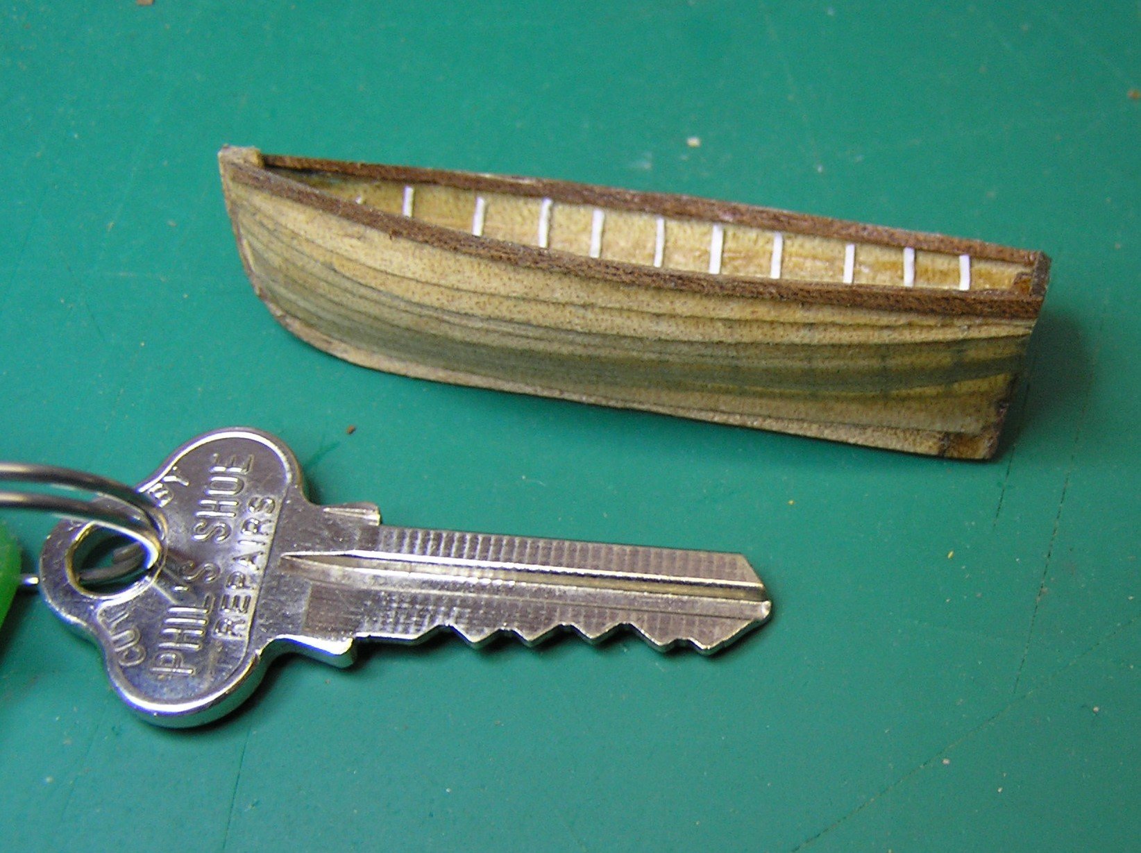
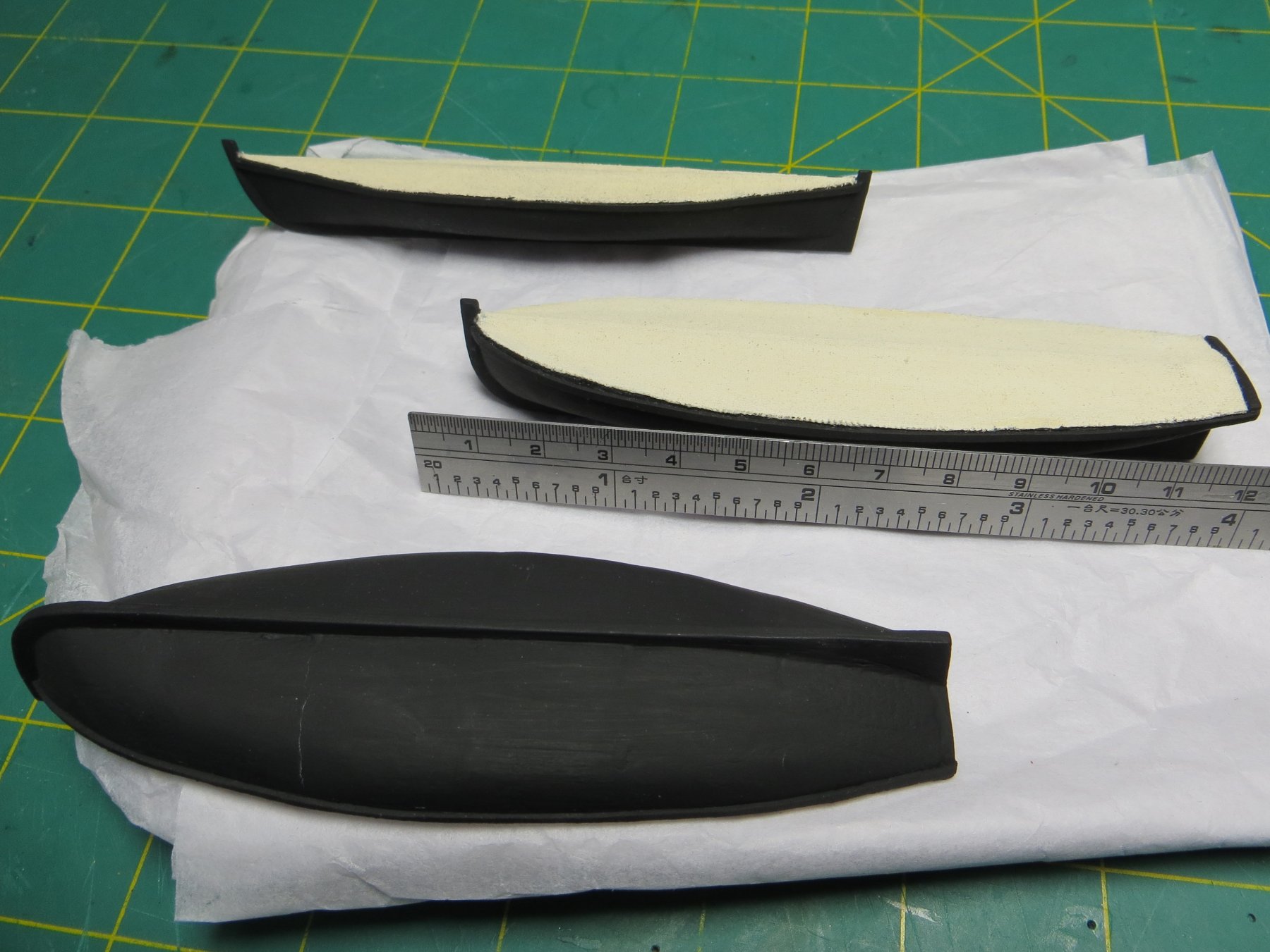
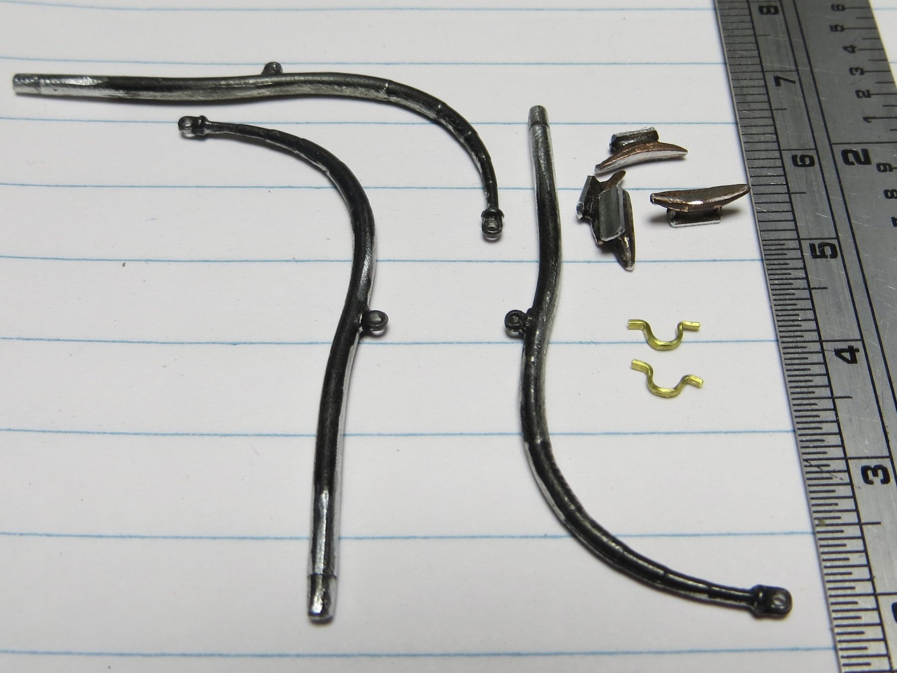
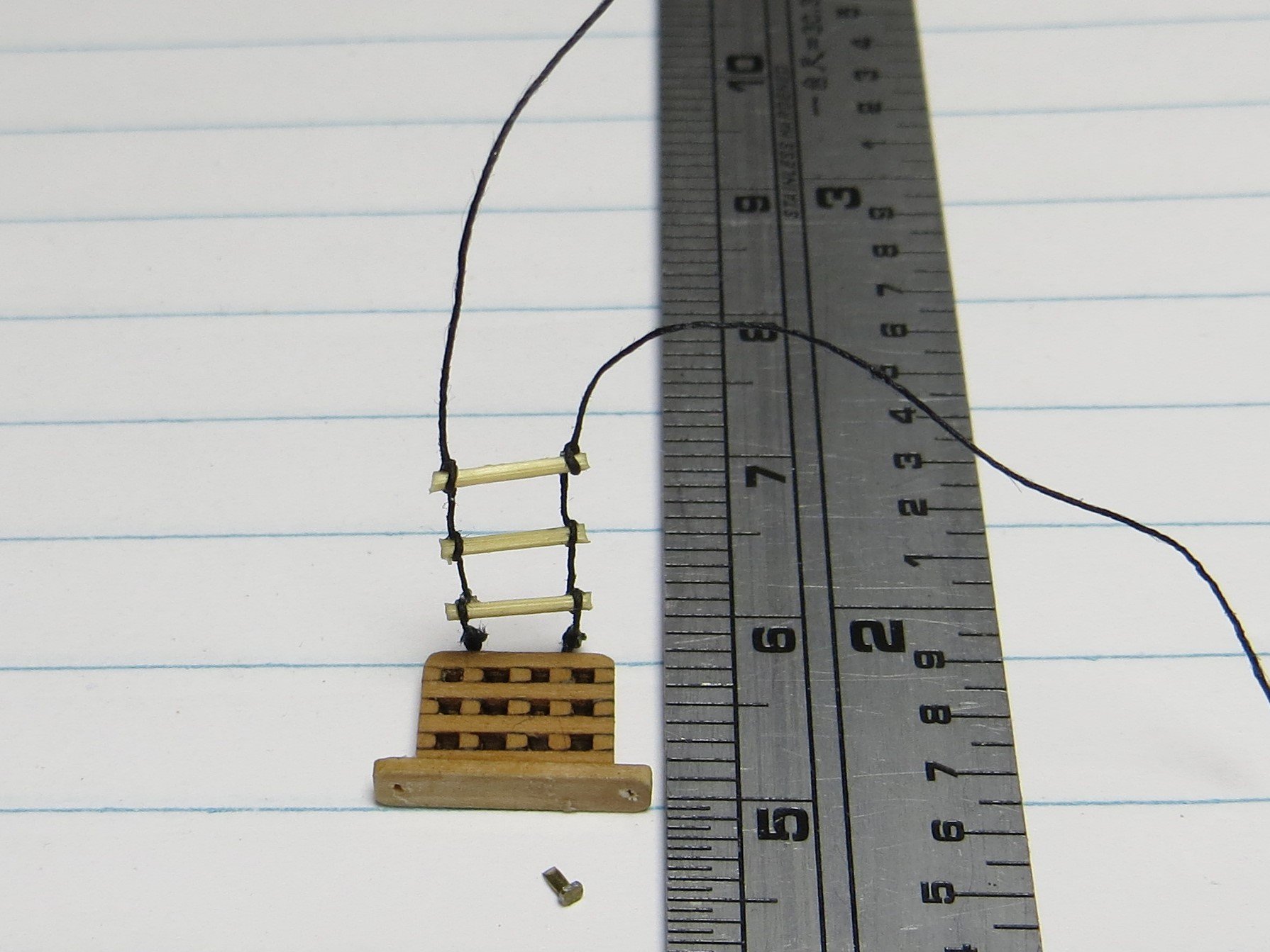
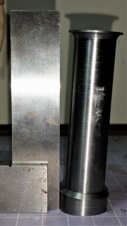
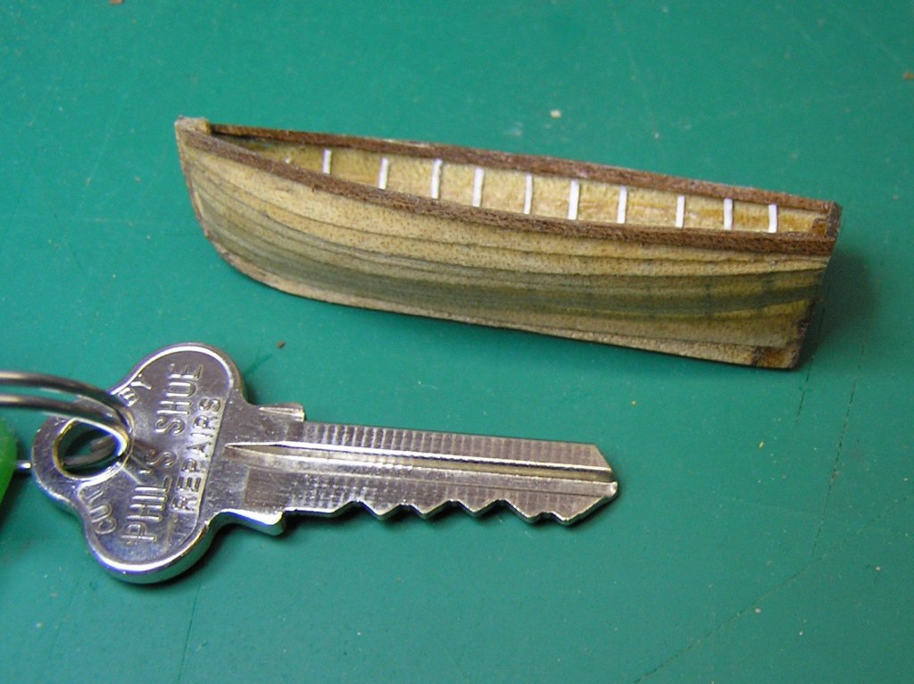
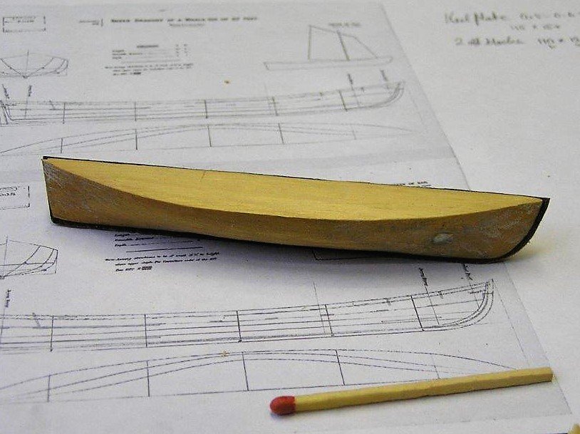
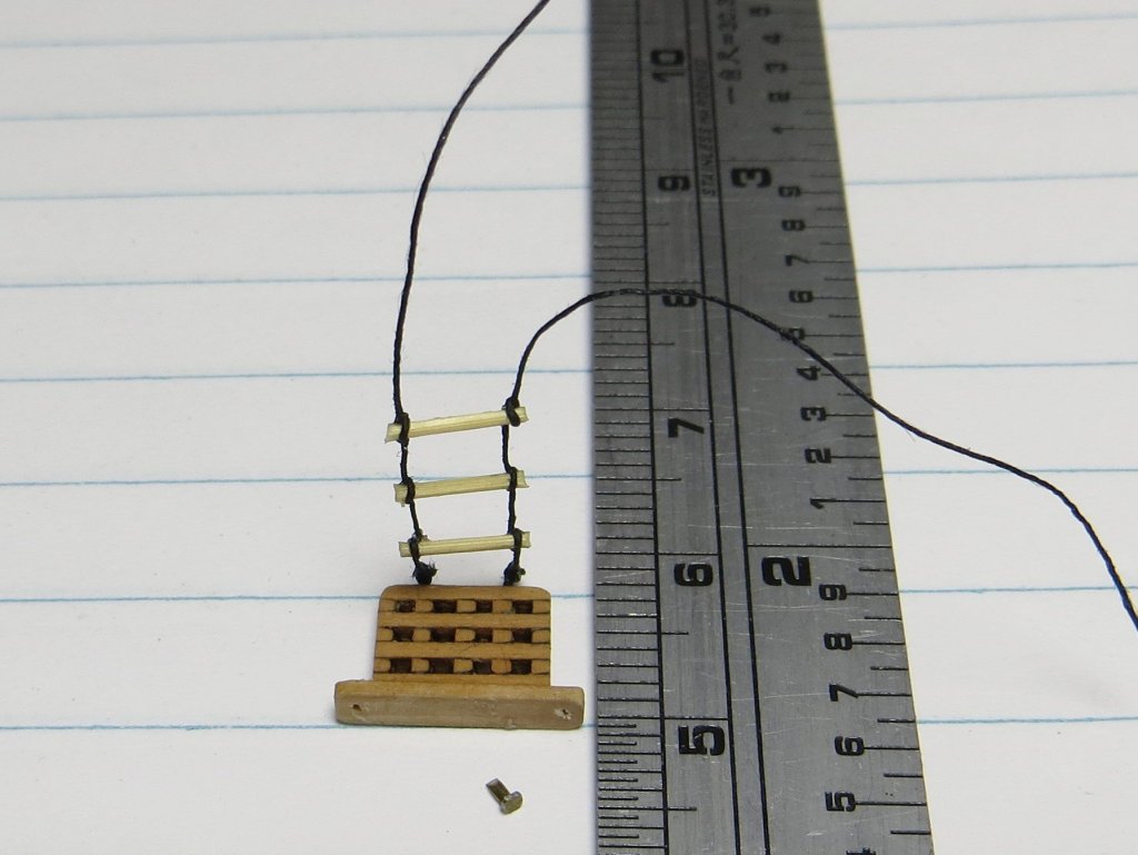
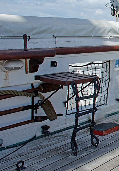
Hi again folks, a small update. Not too much to show on the model itself yet as I am preparing as much as possible on the bulwarks so that once painted i do not have to revisit them much after that. This for 2 reasons; the first is that once the deck furniture is fitted there will be limited space to add anything to the bulwarks, and, as they will be flat white, and small marks will show up easily. In the meantime, two other members and I have been progressing a few parts ready to for fitting. The first is the cathead as shown below. This is at an angle of 45 degress, which is consistent with what is shown in the lithographs and with HMS Warrior (1860) . I have also made the small anchor release mechanism that will fit to the top of these (not shown). The groove is to accept the whisker which will be fitted later - too prone to damage at this stage :). Based on info held so far, I do not believe there was any ornamentation at the end of the cathead timber. As can also be seen from the the closeup camera detail, a lot more sanding and preparation is still needed. A friend (same one who did the screw) has started the on the funnel. this is the turned base to which all the required detail will be fitted. False bands to representing the telescoping components, a spider band for the chain stays, and the waste steam pipe are yet to be added along with simulated riveting. I have also made the platform for the Leadline handler which will be fitted to the stbd side bulwark and is located just under the cap rail (roughtree rail). A jacob's ladder is fitted for accessing the platform and two stanchions will be fitted into the cap rail with a leather belt between them to support the crewmember as he leaned out. The rough timber closest to camera will be glued to the bulwark and false bolts fitted either side of the platform. Another board will be added, along with eyebolts, to the port side as the platform could be moved to either side. The other photo is what I am trying to achieve at scale (eventually). As the camera has pointed out, I need to trim the rung ends a little - the camera is useful for finding this sort of detail as the platform is only 8mm x 10mm. [Edit: actually, I think I will redo the jacob's ladder; that ladder looks too crude One club member had started on the boats, but only completed three before he sadly passed away suddenly. Another member has volunteered to complete them (all shown below). Four of the boats, the two lifeboats, Gig and Whaler) will be shown with canvas covers fitted and the dinghy, which will be on the stern davits, will be open. These boats will all be repainted to be the same shade of black as the hull. You can see how small these are :). Dinghy Whaler plug with partial planking on other side complete. Completed lifeboats and Gig I have started work on the davits as these need to be fitted to the outside of the bulwarks. I have shaped the main davits, modified some shroud cleats which will be added and have yet to add some eyes to the davit head for the chain stays. See separate post on this. cheers Pat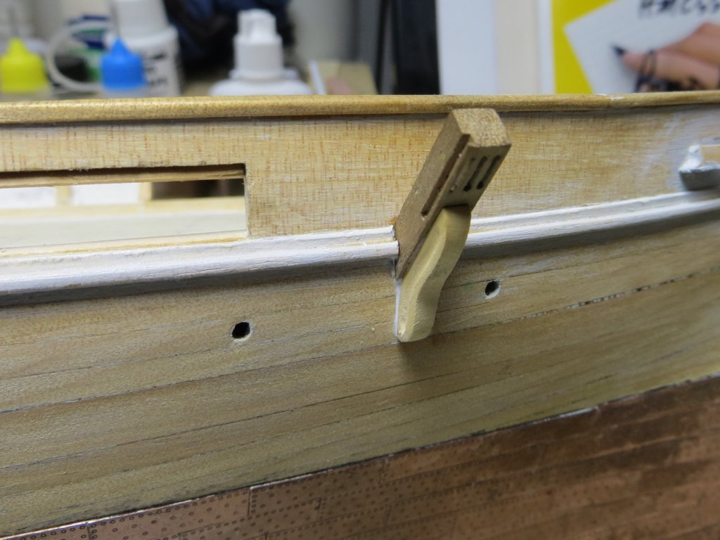

- 1,021 replies
-
- 13
-
-
- gun dispatch vessel
- victoria
- (and 2 more)
-
Great work on that spar Ed; if it took you three goes, I know I will need 6. I need to do a couple of these for the Victoria . Thanks for the link also, those barrette files look very useful so I will need to invest. cheers Pat
- 3,618 replies
-
- 1
-
-
- young america
- clipper
- (and 1 more)
-
Great work Jason; your build is coming together very nicely indeed. Enjoy your holiday. cheers Pat
-
Thank you for sharing this (and the many other) techniques; helps to inform us all. What type of file are you using there with the tapered back shoulders? cheers Pat
- 3,618 replies
-
- 4
-
-
- young america
- clipper
- (and 1 more)
-
Stunning detailing Greg, and a great addition to your rapidly expanding fleet - I feel positively slow compared to your rate of building Impressive model. cheers Pat
-
Really nice Russ, that planking is very well done. cheers Pat
- 420 replies
-
- 4
-
-
- captain roy
- lugger
- (and 2 more)
-
You're becoming a dab hand at this cutting lark Danny, those funnel bases look very trim and neat! cheers Pat
- 295 replies
-
- 7
-
-
- amatsukaze
- halinski
- (and 2 more)