BANYAN
-
Posts
5,965 -
Joined
-
Last visited
Content Type
Profiles
Forums
Gallery
Events
Everything posted by BANYAN
-
 Great info Ed, and you were very meticulous in your work - would never know that they had changed. I will need to watch for similar lead issues when i get to the rigging. cheers Pat
- 3,618 replies
-
- 2
-

-
- young america
- clipper
- (and 1 more)
-
The yards came up well Rusty, nice work. cheers Pat
- 310 replies
-
- 2
-
-
- cheerful
- Syren Ship Model Company
- (and 1 more)
-
What grit for disc sander?
BANYAN replied to clifforddward's topic in Modeling tools and Workshop Equipment
Thanks Bob, those 3M products look great. cheers Pat -
Great progress; she is looking very grand Dan cheers Pat
- 287 replies
-
- 5
-
-
- michelangelo
- ocean liner
- (and 1 more)
-
Nice work Jason, those bitts and the manger look great. cheers Pat
-
Frustrating indeed Ed, some surprises for the future when someone xrays or takes a peek inside She is really looking good with more of her finery added. cheers Pat
- 3,618 replies
-
- 3
-
-
- young america
- clipper
- (and 1 more)
-
Ditto! Very clean well executed rigging. cheers Pat
-
Great to see you back in the shipyard Dave, glad to hear you had a ggood trip. cheers Pat
-
A very practical and useful jig, thanks for sharing cheers Pat
-
Hi Neil, very early in my Endeavour build i followed a recommendation to paint the bottom of my hull with bitumen. I acquired a small can of the bitumen based undercar preserving compound and applied it as was. It looked great and really simulated the 'brown stuff' used on the hulls before white stuff really well. It dried reasonably well but as Druxey states not completely. Then along came summer and you can guess what happened, it MELTED and went all over the base etc. Lesson learned, I scraped it off then tried to remove the residue with turps etc but the liquid part of the solution had really penetrated the wood. the end result was an unexpected really pleasing outcome as it applied a very nice patina to the walnut planks. You can see the difference in the following photo. 1. Don't apply as bitumen! 2. Look for smaller quantities in the under car body/chassis preservation compounds . cheers Pat
-
Good luck with the move, they can be quite stressful. Looks like you have moved your models Ok - quite the collection you have. cheers Pat
- 786 replies
-
- 2
-
-
- Royal Louis
- Finished
- (and 1 more)
-
HMCSS Victoria 1855 by BANYAN - 1:72
BANYAN replied to BANYAN's topic in - Build logs for subjects built 1851 - 1900
Thanks for looking in Denis, and the kind comments. cheers Pat- 1,021 replies
-
- 2
-
-
- gun dispatch vessel
- victoria
- (and 2 more)
-
Extraordinary - what a whopper of a ship! Very nice work Gaetan, I look forward to your detail work. cheers Pat
-
I am sorry I missed this so much earlier, a truly inspiring build. I very much like the detail being applied; artisans at work :). cheers Pat
-
HMCSS Victoria 1855 by BANYAN - 1:72
BANYAN replied to BANYAN's topic in - Build logs for subjects built 1851 - 1900
Hi Elijah, yep genuine copper They are at correct scale of 1:72 and the sets come pre-stamped for port and stbd sides so you can get the pattern correct. They are from AMATI I think (I will have to go back and check). cheers Pat- 1,021 replies
-
- 2
-
-
- gun dispatch vessel
- victoria
- (and 2 more)
-
HMCSS Victoria 1855 by BANYAN - 1:72
BANYAN replied to BANYAN's topic in - Build logs for subjects built 1851 - 1900
Thanks for looking in Carl, Ed and Jason, much appreciate the feedback. Yep Carl, a 'tad' fiddly at 1:72 but if I can get half as good as Ed at it I will feel I am starting to accomplish Thanks for the tip on using the vise Ed, I'll give that a try. I am also going to give the 'jeweller's mitre' I have a go. Using the same technique of nipping off just above the face plate and peening with the mitre jig held in a vise with the face facing up. I hadn't thought of that until your timely input. I also need to go back through your work again to refine my polishing technique; I am still not controlling the 'piece' enough and it moves while filing - I think I need to get a better small vise Thanks Jason, appreciate these comments after seeing your meticulous work. As this is a 'club' build, I find I am often trying to repair/improve on some of the 'finish' applied by others - but in this case the copper sheathing plates were applied by a fellow club member (his first attempt at doing coppering) and he did a great job - I just needed to tidy up after cutting the holes etc for the pintles and glue back a couple of plates I dislodged in the process cheers Pat- 1,021 replies
-
- 4
-
-
- gun dispatch vessel
- victoria
- (and 2 more)
-
HMCSS Victoria 1855 by BANYAN - 1:72
BANYAN replied to BANYAN's topic in - Build logs for subjects built 1851 - 1900
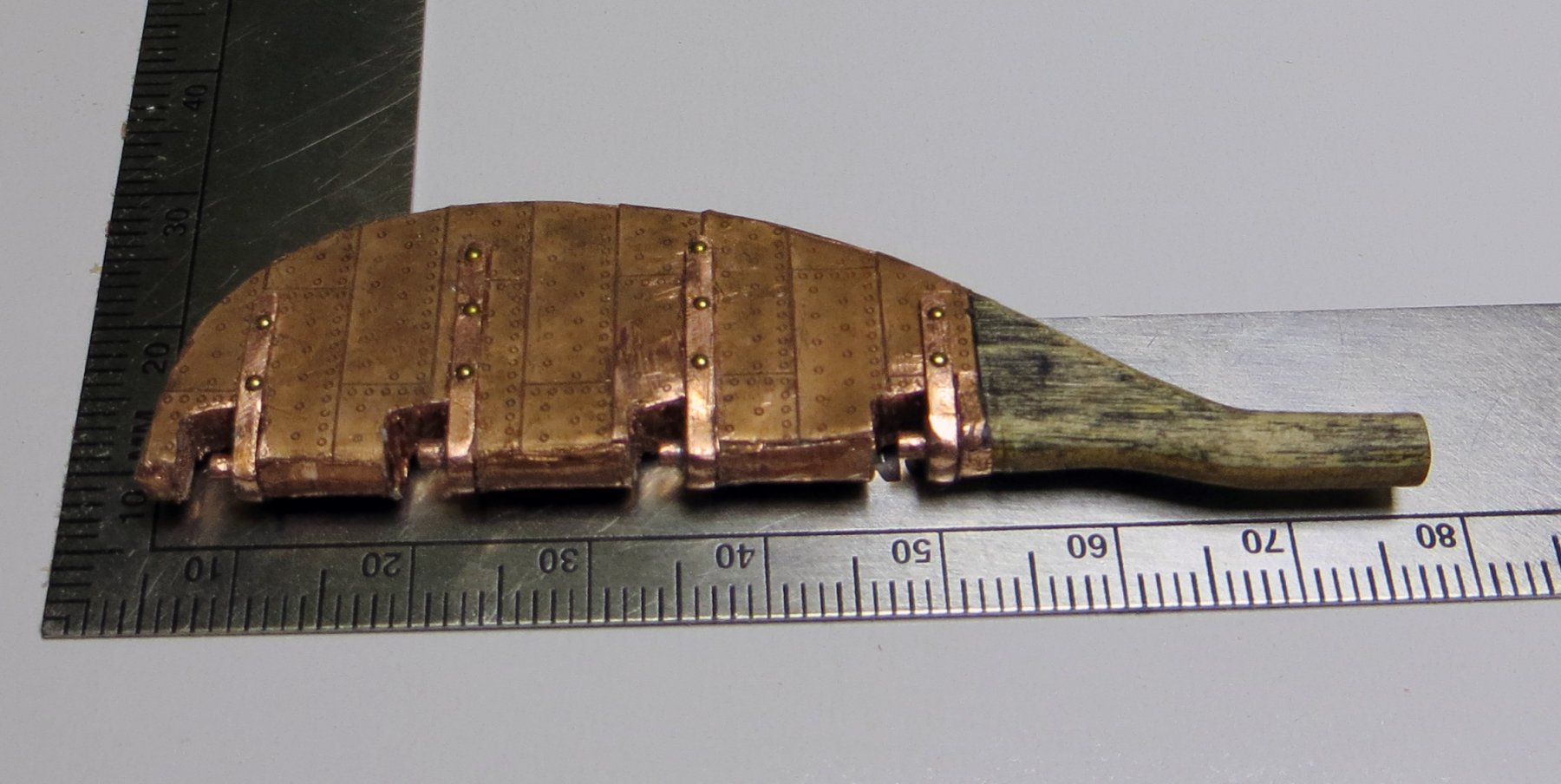
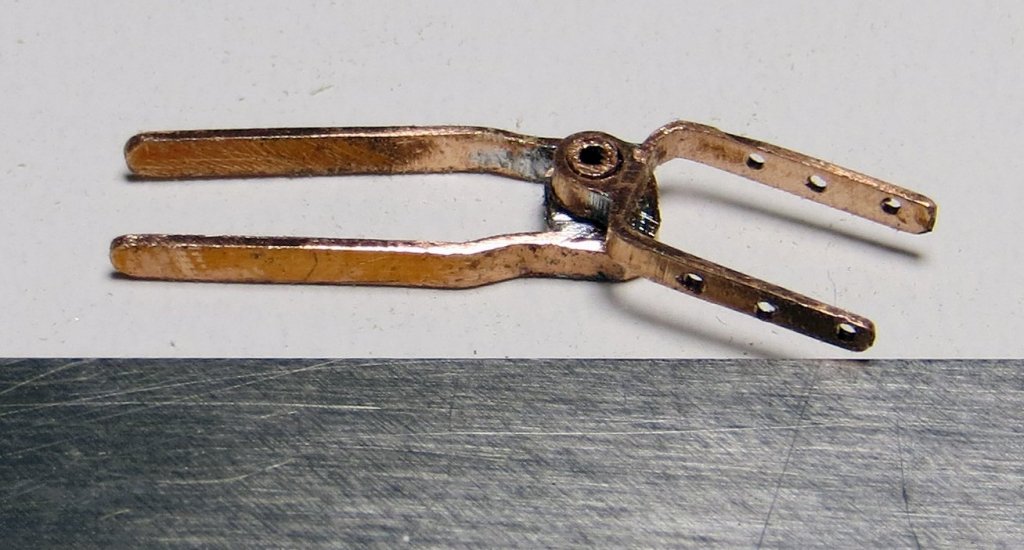
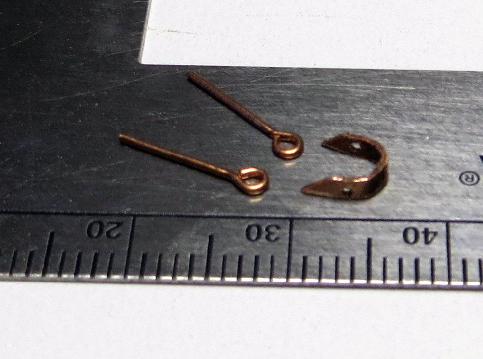
Hi folks. Some further progress on the rudder which is now ready to hang. Below is the process for making the pintles which was made by first soldering two telescoping tubes of copper together to get to the right size for the leading edge of the rudder. This thicker walled tube was then soldered to the the copper plate which was then cut on my hobby saw to the right strap thickness. The was pintle was then shaped on a former to the same thickness as the rudder blade. The photo with the raw materials shows the telescoping tubes with the smaller being the same size as the mating hole in the gudgeon. The photo showing a near complete pintle (still to be drilled) and gudgeon shows a nice tight fit - the pintle still has cleaning of the solder to be completed. Everything is made of copper except the nails I used to simulate the rivet heads which are brass. i tried making some small nails but have yet to refine/improve my technique (based on Ed Tosti's method) and really need to make a jig for this. With my nerve issues I find I cannot hold the wire in a plier with grovve as Ed does. These turned out okay as shown in the completed rudder, which I will hang after painting the rudder head and fitting the strap and eyes to accept the emergency chains and shackles. cheers Pat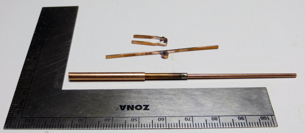

- 1,021 replies
-
- 18
-
-
- gun dispatch vessel
- victoria
- (and 2 more)
-
Good luck with the move Michael - hopefully no new repairs needed the other end cheers Pat
-
You don't muck around do you Danny. This will be another interesting build so I'll pull up a chair also. cheers Pat
-
So, a little easier than Vulture (but not much) Nice work Danny. cheers Pat
- 295 replies
-
- 4
-
-
- amatsukaze
- halinski
- (and 2 more)
-
Hi Gaetan, you could also try to make her like an 'accordion' with a flexible bellows type construction to shorten/lengthen as required Nice work by the way cheers Pat
-
You have made a lot of nice looking progress Greg, she will look a treat when completed. cheers Pat
-
Kurt, I found taking small amounts each pass worked best as there is less chance of the 'kickback' especially with small pieces. I use about a 1/3 turn of the front wheel -usually works for me. If you do try to take more off make sure you are not standing behind the entry/feed side just in case of kickback - I usually work with the sander across my body so it feeds right to left. With very thin and small pieces try using double sided tape (such as carpet tape) to hold the piece to a larger carrier piece. cheers Pat