BANYAN
-
Posts
5,969 -
Joined
-
Last visited
Content Type
Profiles
Forums
Gallery
Events
Everything posted by BANYAN
-
 Noce progress Dave, looking very shipshape. Your rigging work is very neat. cheers Pat
 -
You're making very good progress Dashi; those yards look good. The boats look great nicely 'stowed' on deck and still leaves plenty of room to work around them. cheers Pat
-
HMCSS Victoria 1855 by BANYAN - 1:72
BANYAN replied to BANYAN's topic in - Build logs for subjects built 1851 - 1900
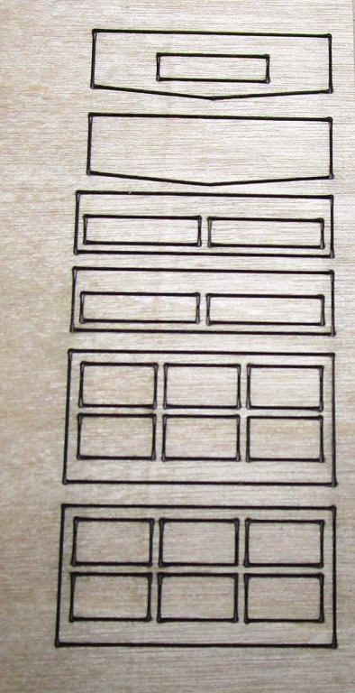
Hi Dave and Carl; thanks for looking in and comments. Dave, I drew the base artwork marking what I needed as etched on the underside or upper side, showing where I need holes etc. these were done to the required print/etch scale in TurboCAD and passed to the etcher who imported them and turned them direct into his 'negatives'. This is a screen grab of wwhat I drew up. Many thanks again for organising the lasercut for me; it has worked out well with the PE fitting very well. Now to glue the assemblies together and add the 'dadoes'. Carl, I finally caught up with a guy (Model Railroad community here in Melbourne) who had done some etching for my Endeavour and he did this job for me. I do so little that it is not worth the added expense/complication of learning yet another skill. Still a bit more photoetch to be done for all the mast work etc, but that will come in due course Most of this is for the Rigmaiden Lanyards, purchase winches etc. cheers Pat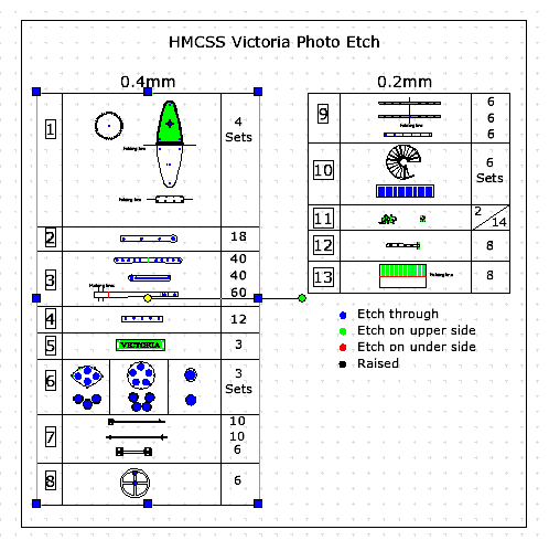
- 1,021 replies
-
- 5
-

-
- gun dispatch vessel
- victoria
- (and 2 more)
-
HMCSS Victoria 1855 by BANYAN - 1:72
BANYAN replied to BANYAN's topic in - Build logs for subjects built 1851 - 1900
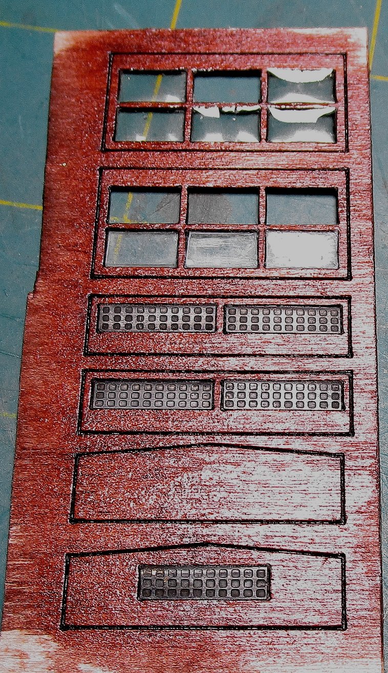
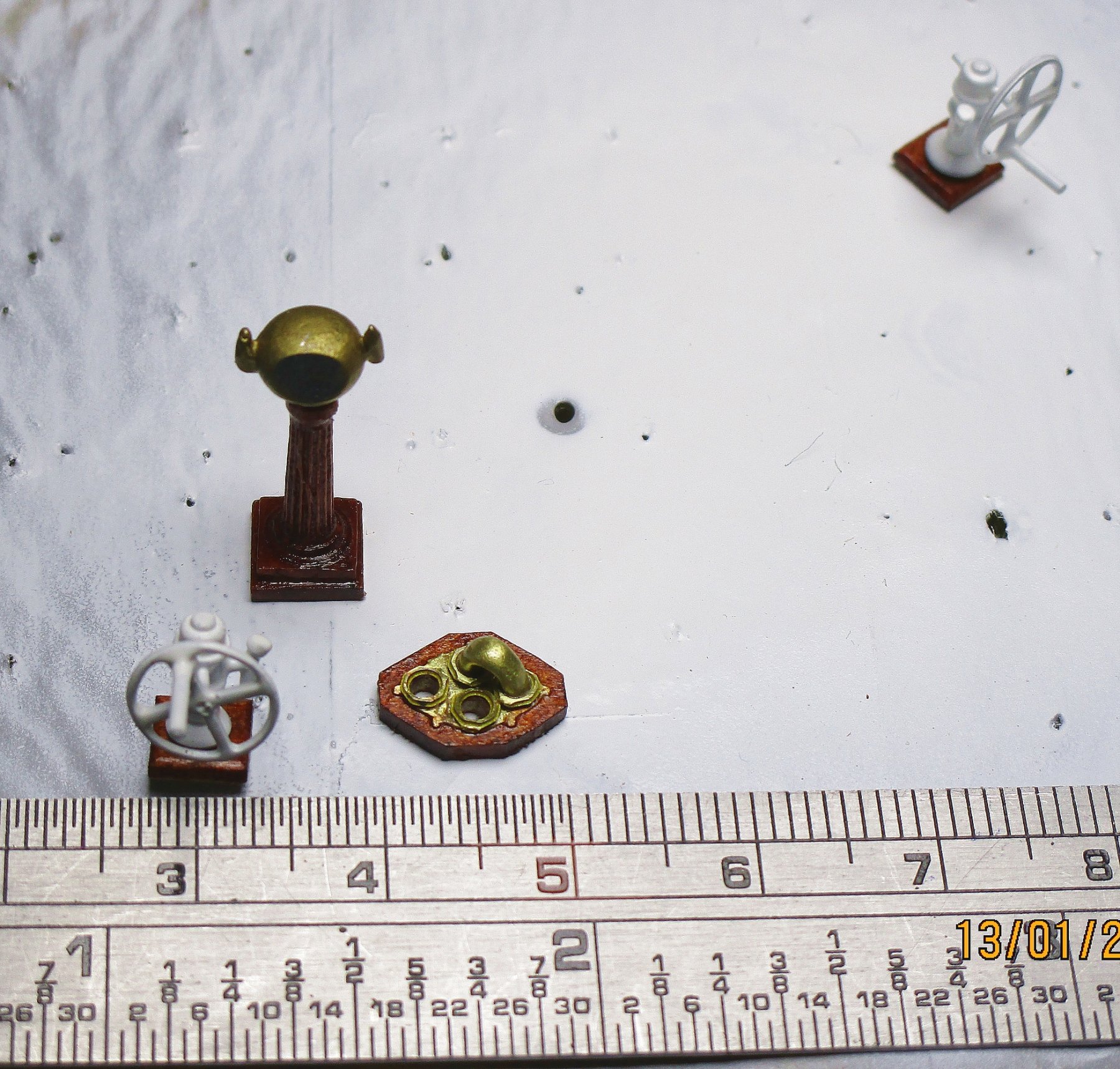
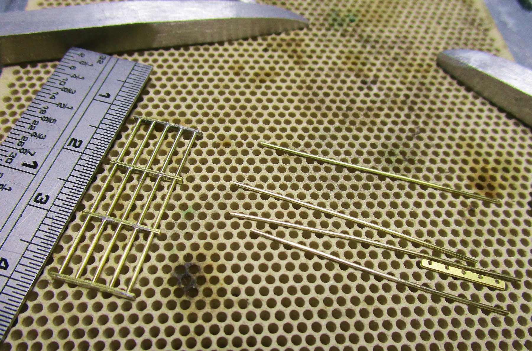
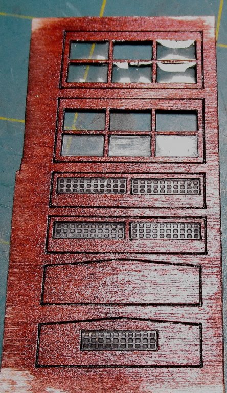
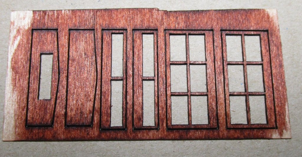
Hi folks, another small update. Now that I have the PE in hand I can progress on a bit; still waiting for the 3D parts (capstan and revised funnel). I also had some laser parts cut for the engine room skylight as my attempts to make them kept breaking (stiles and rails) as the walls are only .6mm thick and the rails /stiles just .8mm. They have come up OK considering the size. One of the reasons for lack of updates is that I had been busy drawing up all these part. The two sheets of PE are 0.4mm (larger sheet) and 0.2mm. I am in the process of doing the glazing and have added the 'waffle' style ventilation louvres discussed earlier. The louvers were made from 0.2mm thick brass sheet and folded and soldered to get the effect seen in the photo earlier - they look OK I think? My biggest decision is whether to add another louvre in the front and after walls. I show a blank and a louvre version in the photos, but have an additional one of each. My thoughts are to go for blank (no louvre) as I think there would have been adequate ventilation from the louvres and top pieces? The reasoning is that the after wall would most likely have been used to store the firehose racks, and supplementary 'L' shaped handle for the Downton pumps (only shipped as required. I have started on the rod/bar grills for the top pieces with the parts shown before cleaning (one made, one unmade); the rods are only 0.6mm diameter. These have since been blackened but I forgot to take a photo. When the glazing in the top pieces have dried completely these will be glued over the windows / glazed parts. I have also made the bases for the pumps, and manufactured one of the two suction plate assemblies required. The idea was that the connecting pipe(rounded/horseshoe shape) could be cross-connected to any one of three suction pipes (one to each major compartment/space). The top end of the pipe ran underdeck between the pipe and this plate assembly. I still have a 7" hose connection plate (single) to make which was the upper deck connection to the pump in the engine room (for firefighting) whereas the other two are for dewatering and transferring freshwater around the ship. The wood looks rough but I am zoomed right in and actually looks very smooth to the eye. The 'pelorus' has also been completed. The 'hollow' look of the brass night cover for the compass is a trick of the light as I have painted that face silver to simulate the viewer. These parts will be fitted once the engine room skylight has been fitted. cheers Pat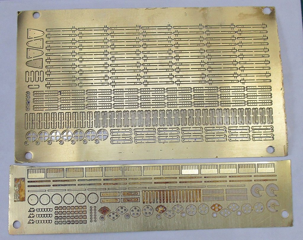


- 1,021 replies
-
- 10
-
-
- gun dispatch vessel
- victoria
- (and 2 more)
-
You are motoring along Rob, very tidy! cheers Pat
- 1,208 replies
-
- 1
-
-
- great republic
- clipper
- (and 1 more)
-
Your joinery is an inspiration! cheers Pat
-
That's very effective 'lagging' GL, and nice detail. cheers Pat
- 219 replies
-
- 1
-
-
- smack
- cross-section
- (and 2 more)
-
Great progress UV and love the 'life's little adventures' along the way I cannot recount the number of time I went looking for things only to find them in the most obvious place cheers Pat
- 786 replies
-
- 2
-
-
- Royal Louis
- Finished
- (and 1 more)
-
Missed the start of this one Steven, will be following with interest. cheers Pat
- 740 replies
-
- 1
-
-
- Tudor
- restoration
- (and 4 more)
-
The cheapest way is to make them yourself if you have the time. These can be turned up on a lathe from brass, alluminium or wood rod (stock); or, buy/make one master and cast the remainder of them? If you are willing to buy, have a look at ship model accessories at the many hobby shops/retailers and they stock additional/replacement parts from some of the bigger mass produced kits. You may find something that looks a bit like the guns you need close to scale made from britannia/white metal. Not as nice as brass turned barrels but a lot cheaper - but as the saying goes "you gets what yous pays" - Buying cheap will most often mean they will look 'cheap' on the model also unless you put a lot of additional work into them. cheers Pat
-
Hi Oliver, as Mark points out some masts were painted, others not. To establish what the masts in your ship/model were you need to research the ship and see if there is a common way of doing things for that era in the form of regulations, contract requirements, or for other ship contemporary for the period. Some ship's logs are great as there are often entries such as stripping and varnishing the lower masts etc. If painted, again need to know the normal practice for that period in a war/merchant ship (they often differed) and in latter times mast colours were often governed by the owners/shipping line etc. If you decide to paint, as Mark points out, you can either paint or leave bare, or use different wood types to 'paint by wood' as some modellers call it. A lot of ship masts were simply varnished and the normal weathering of varnish (on a model) may be sufficient for your needs. if painting, sometimes you need to 'tone down' the hue of the colour of the paint a bit for the model to keep the paint in perspective to the model. Basically you need to research the ship type, era etc a bit first so that some of the more experienced here can then provide some better, more specific advice.
-
Very nice work Michael, and a mioni-tutorial on making those slotted round head screws to boot She will be a work of art and just too nice to put into the water cheers Pat
-
HMCSS Victoria 1855 by BANYAN - 1:72
BANYAN replied to BANYAN's topic in - Build logs for subjects built 1851 - 1900
Hi Rob and Michael. Many thanks for looking in and very kind comments. Best wishes for the New Year to you all also. cheers Pat- 1,021 replies
-
- 3
-
-
- gun dispatch vessel
- victoria
- (and 2 more)
-
Thanks for the feedback Rob. I am with you there; now prefer unusual subjects also. cheers Pat
- 1,208 replies
-
- 2
-
-
- great republic
- clipper
- (and 1 more)
-
May be slow progress Dave, but she is looking great. Those rope ends look all nice and ship-shape! I made life a little easier with my display base by using two thinner pieces of wood with the first (lower) being the larger (overall) size, then placing a second cut to the inner dimensions of the acrylic on top. No need for slots etc cheers Pat
-
Nice work Rob. Were the red handles just make them stand out or was that the acual colour (from research)? cheers Pat
- 1,208 replies
-
- 2
-
-
- great republic
- clipper
- (and 1 more)
-
HMCSS Victoria 1855 by BANYAN - 1:72
BANYAN replied to BANYAN's topic in - Build logs for subjects built 1851 - 1900
Thanks Jason. cheers Pat- 1,021 replies
-
- 2
-
-
- gun dispatch vessel
- victoria
- (and 2 more)
-
Great ideas and technique Michael, the support for the saw blade is one that I will definitely file away. cheers Pat
-
Nice work Greg. Those cranes may be just what I am looking for also Are they part of the kit PE or aftermarket? cheers Pat
-
Happy New Year t you too mate. Very (VERY) nice work on those channels, brackets and guns Jason. Those are very neatly executed brackets and look just right. cheers Pat
-
Nice work G.L. , really like the iron (brass) knees cheers Pat
- 219 replies
-
- 2
-
-
- smack
- cross-section
- (and 2 more)
-
Oh you do love a challenge Greg, that PE looks more than a little difficult! Good luck The paint effect is very good and representative of a well worn 'work horse' of the fleet. cheers Pat
-
Sitting at the back has its advantages mate; I can heckle and throw things further than you could throw them back and up Look forward to seeing your efforts on this build also. cheers Pat
-
Taking a back row seat to see what you do with this one Carl, looks like you have taken a liking to RCN ships? cheers Pat