BANYAN
-
Posts
5,964 -
Joined
-
Last visited
Content Type
Profiles
Forums
Gallery
Events
Everything posted by BANYAN
-
 If you can do that with a head cold, it is no wonder your other work is so good. cheers Pat
 -
Dave, I think AOTS had cleats on the inboard part of the bowsprit instead of belaying pins? Nice job on the additions. cheers Pat
-
HMCSS Victoria 1855 by BANYAN - 1:72
BANYAN replied to BANYAN's topic in - Build logs for subjects built 1851 - 1900
cheers mate; appreciate your compliment. cheers Pat- 1,021 replies
-
- 3
-

-
- gun dispatch vessel
- victoria
- (and 2 more)
-
HMB Endeavour by mikec - Eaglemoss
BANYAN replied to mikec's topic in - Kit build logs for subjects built from 1751 - 1800
Great to see you back Mike; hope to see your updates soon. cheers Pat -
That's looking very good Vossiewulf - very crisp work. cheers Pat
- 714 replies
-
- 2
-
-
- lady nelson
- victory models
- (and 1 more)
-
As Mark says, nice to see the shipyard back at work again Gaetan. Very clean work. cheers Pat
-
HMCSS Victoria 1855 by BANYAN - 1:72
BANYAN replied to BANYAN's topic in - Build logs for subjects built 1851 - 1900
Thanks for looking in and the comments Carl, Mark and Patric - much appreciated. Now to attack the circular skylights, that is going to be a bit of a challenge but only 4 to make 😨 - . cheers Pat- 1,021 replies
-
- 4
-
-
- gun dispatch vessel
- victoria
- (and 2 more)
-
More of your excellent work Ed; that rigging looks really good - love the colour of your running rigging. cheers Pat
- 3,618 replies
-
- 3
-
-
- young america
- clipper
- (and 1 more)
-
That looks very good Rob, the level of detail at the scale you are building is excellent. cheers Pat
- 1,208 replies
-
- 2
-
-
- great republic
- clipper
- (and 1 more)
-
Looks pretty good to me Dave; rope still appears proportionate to the buoy size even if a 'tad' oversize. cheers Pat
-
You would never of known had you not tried Rob. One day a new idea may 'pop-into your head' but for now we will enjoy the sails you have done. cheers Pat
- 1,208 replies
-
- 2
-
-
- great republic
- clipper
- (and 1 more)
-
HMCSS Victoria 1855 by BANYAN - 1:72
BANYAN replied to BANYAN's topic in - Build logs for subjects built 1851 - 1900
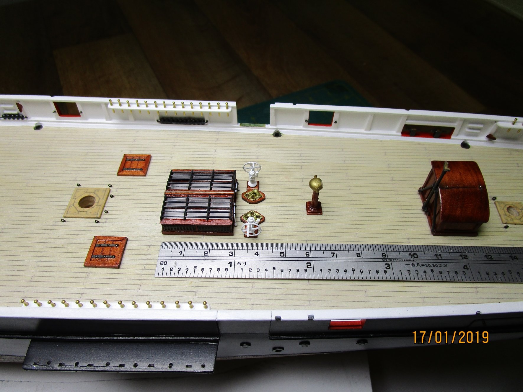
Another small update folks. This shows some of the completed parts in-situ but the 'pelorus' is only dry fitted. I have yet to add the connection point (hydrant) for the 7" fire pump between the two suction plate assemblies, and a few sounding pipes. There is also a brass (single) rail to go around this area. Dave, the laser cut came up well; many thanks to you and your mate for organising this for me. The rod grills are made from PE verticals and .6mm brass wire/rod which I soldered at the ends (each rod) and spot soldered two rods only for the inner ones. I have rebated a length of 0.5mm brass rod into the centreline piece of the skylight to represent a 'piano style' hinge with the edges screwed off against the sides of the panels in real life. Unfortunately the laser cut ply came up a little darker than the rest of the wood (Kauri) but I think I can live with it I have also fitted the two 'L' handles for the downton pumps against the rear end of the skylight. These were only fitted when required. The dado along the bottom is 8" (actual) which corresponds with the dado on the circular skylights (4 of, still to be made) which will be fitted two abreast between the pelorus and companion, and the other two abreast aft of the companion. cheers Pat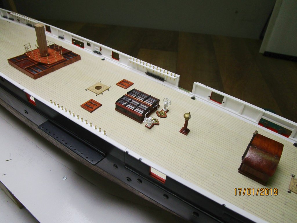

- 1,021 replies
-
- 20
-
-
- gun dispatch vessel
- victoria
- (and 2 more)
-
That should be a very nice 'home' for her Rod. Something I amy do with my nxt case is add some 'strip' leds around the inner bottom edge for better lighting. cheers Pat
-
Quite the crew and dignitary ensemble you have there Steven; they look good and far superior to anything I could carve. As you say, the more practice and times repeated certainly improve skills. The pseudopation is coming along very nicely also. cheers Pat
-
Lovely work Doris on the model and the dolphin support stand; and thanks for sharing the process. cheers Pat
- 1,035 replies
-
- 5
-
-
- royal katherine
- ship of the line
- (and 1 more)
-
HMCSS Victoria 1855 by BANYAN - 1:72
BANYAN replied to BANYAN's topic in - Build logs for subjects built 1851 - 1900
Thanks guys, a learning curve but well worth the effort Not long for the completed assembly Dave; a tad distracted with babysitting duties today. cherers Pat- 1,021 replies
-
- 3
-
-
- gun dispatch vessel
- victoria
- (and 2 more)
-
On the other hand, if you can pull it off, I think it would look OK and something 'different'. That said, would not the course be one of the first major sails set? cheers Pat
- 1,208 replies
-
- 1
-
-
- great republic
- clipper
- (and 1 more)
-
Noce progress Dave, looking very shipshape. Your rigging work is very neat. cheers Pat
-
You're making very good progress Dashi; those yards look good. The boats look great nicely 'stowed' on deck and still leaves plenty of room to work around them. cheers Pat
-
HMCSS Victoria 1855 by BANYAN - 1:72
BANYAN replied to BANYAN's topic in - Build logs for subjects built 1851 - 1900
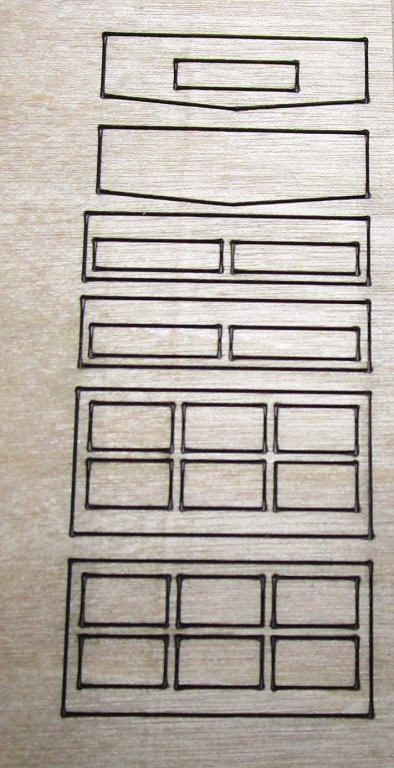
Hi Dave and Carl; thanks for looking in and comments. Dave, I drew the base artwork marking what I needed as etched on the underside or upper side, showing where I need holes etc. these were done to the required print/etch scale in TurboCAD and passed to the etcher who imported them and turned them direct into his 'negatives'. This is a screen grab of wwhat I drew up. Many thanks again for organising the lasercut for me; it has worked out well with the PE fitting very well. Now to glue the assemblies together and add the 'dadoes'. Carl, I finally caught up with a guy (Model Railroad community here in Melbourne) who had done some etching for my Endeavour and he did this job for me. I do so little that it is not worth the added expense/complication of learning yet another skill. Still a bit more photoetch to be done for all the mast work etc, but that will come in due course Most of this is for the Rigmaiden Lanyards, purchase winches etc. cheers Pat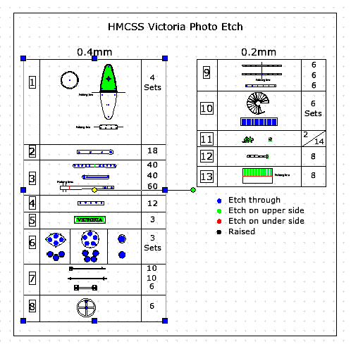
- 1,021 replies
-
- 5
-
-
- gun dispatch vessel
- victoria
- (and 2 more)
-
HMCSS Victoria 1855 by BANYAN - 1:72
BANYAN replied to BANYAN's topic in - Build logs for subjects built 1851 - 1900
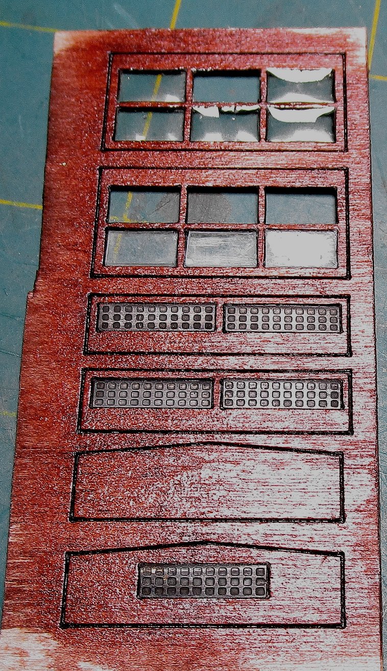
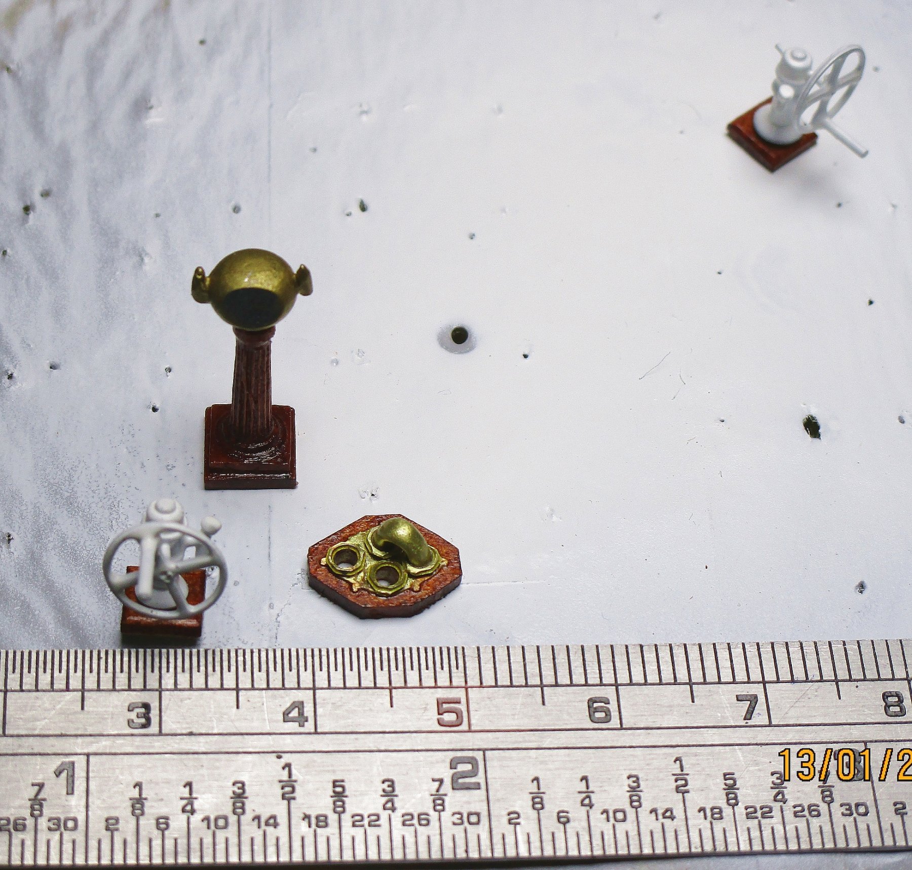
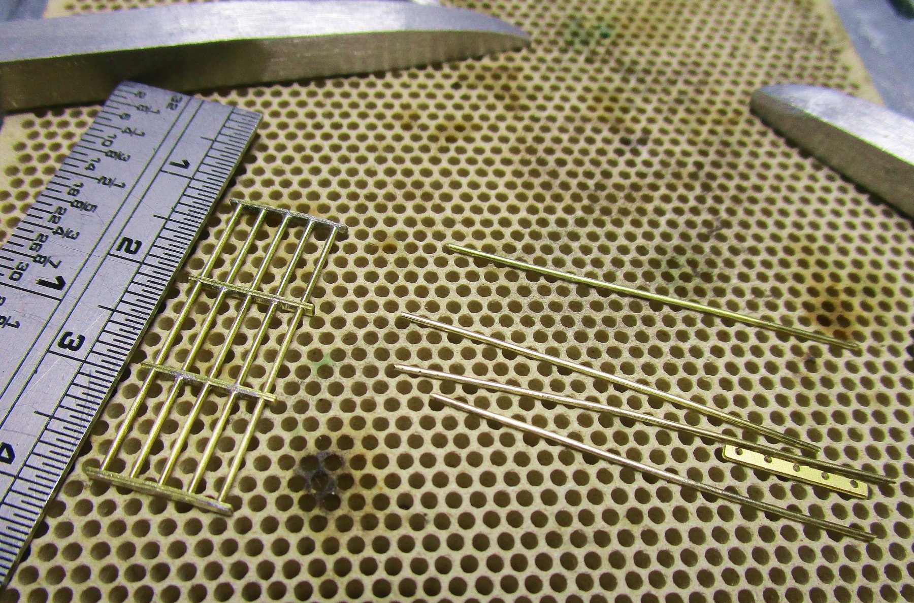
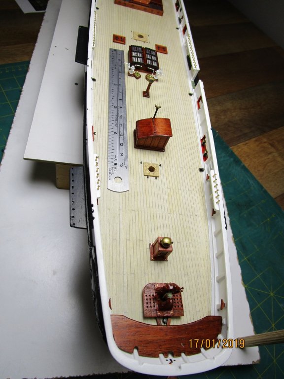
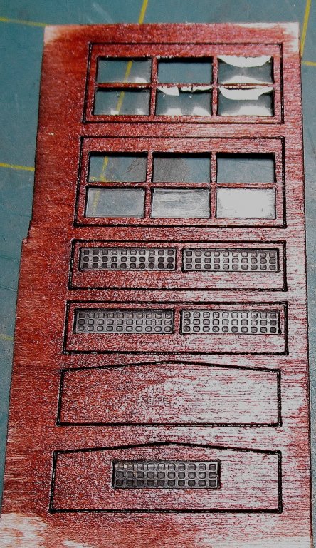
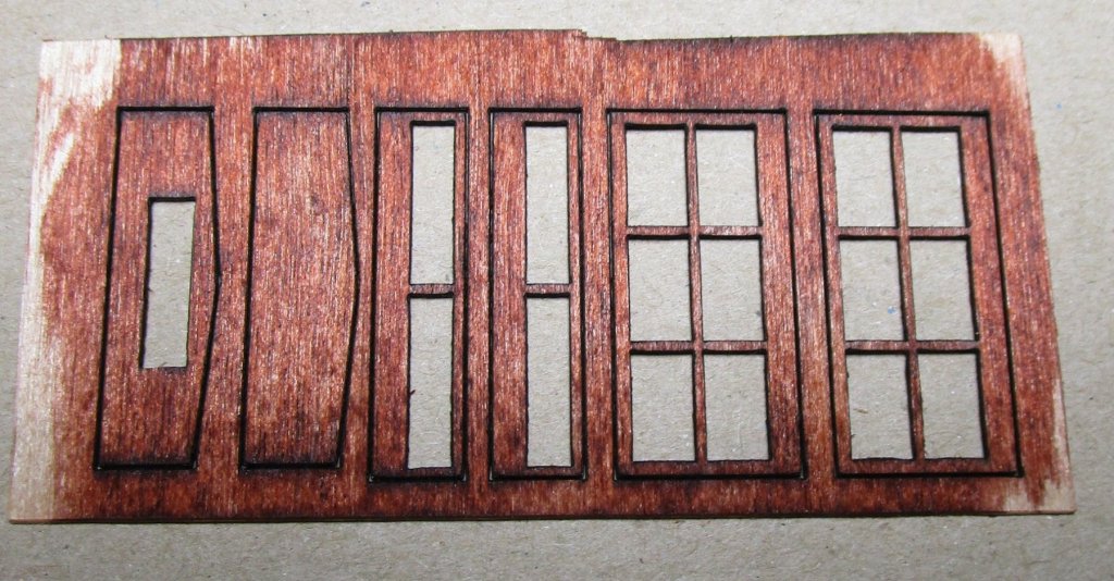
Hi folks, another small update. Now that I have the PE in hand I can progress on a bit; still waiting for the 3D parts (capstan and revised funnel). I also had some laser parts cut for the engine room skylight as my attempts to make them kept breaking (stiles and rails) as the walls are only .6mm thick and the rails /stiles just .8mm. They have come up OK considering the size. One of the reasons for lack of updates is that I had been busy drawing up all these part. The two sheets of PE are 0.4mm (larger sheet) and 0.2mm. I am in the process of doing the glazing and have added the 'waffle' style ventilation louvres discussed earlier. The louvers were made from 0.2mm thick brass sheet and folded and soldered to get the effect seen in the photo earlier - they look OK I think? My biggest decision is whether to add another louvre in the front and after walls. I show a blank and a louvre version in the photos, but have an additional one of each. My thoughts are to go for blank (no louvre) as I think there would have been adequate ventilation from the louvres and top pieces? The reasoning is that the after wall would most likely have been used to store the firehose racks, and supplementary 'L' shaped handle for the Downton pumps (only shipped as required. I have started on the rod/bar grills for the top pieces with the parts shown before cleaning (one made, one unmade); the rods are only 0.6mm diameter. These have since been blackened but I forgot to take a photo. When the glazing in the top pieces have dried completely these will be glued over the windows / glazed parts. I have also made the bases for the pumps, and manufactured one of the two suction plate assemblies required. The idea was that the connecting pipe(rounded/horseshoe shape) could be cross-connected to any one of three suction pipes (one to each major compartment/space). The top end of the pipe ran underdeck between the pipe and this plate assembly. I still have a 7" hose connection plate (single) to make which was the upper deck connection to the pump in the engine room (for firefighting) whereas the other two are for dewatering and transferring freshwater around the ship. The wood looks rough but I am zoomed right in and actually looks very smooth to the eye. The 'pelorus' has also been completed. The 'hollow' look of the brass night cover for the compass is a trick of the light as I have painted that face silver to simulate the viewer. These parts will be fitted once the engine room skylight has been fitted. cheers Pat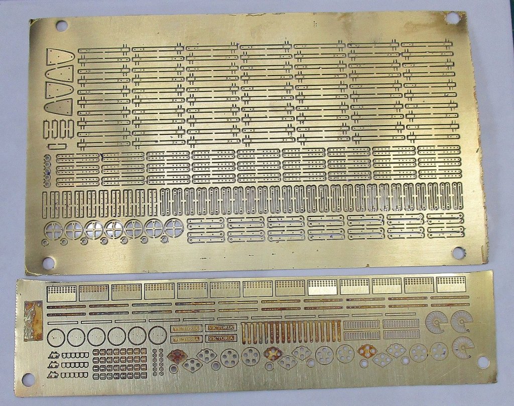


- 1,021 replies
-
- 10
-
-
- gun dispatch vessel
- victoria
- (and 2 more)
-
You are motoring along Rob, very tidy! cheers Pat
- 1,208 replies
-
- 1
-
-
- great republic
- clipper
- (and 1 more)