HOLIDAY DONATION DRIVE - SUPPORT MSW - DO YOUR PART TO KEEP THIS GREAT FORUM GOING! (83 donations so far out of 49,000 members - C'mon guys!)
×


BANYAN
-
Posts
5,946 -
Joined
-
Last visited
Content Type
Profiles
Forums
Gallery
Events
Everything posted by BANYAN
-
 Sorry Rob, nope I didn't add sails (lazy ), but that technique should work well for you. cheers Pat
- 1,208 replies
-
- 2
-

-
- great republic
- clipper
- (and 1 more)
-
Looking good Steve. I found buying the Isop.. cheaper in bulk at Bunnings - although I lost out on all my savings by buying other stuff cheers Pat
-
The shrouds are looking good Rob. I used that technique (complete all mast by mast) with my Endeavour and found it worked well - only i worked from aft to forward as I found it gave me better access for rigging some of the stays etc. cheers Pat
- 1,208 replies
-
- 3
-
-
- great republic
- clipper
- (and 1 more)
-
Hi Rod, generally there was symmetry; however, as usual there are some exceptions to the rule :(. Do you have Marquardt's rigging plan? cheers Pat
-
Welcome back; I trust you have resolved all the issues so that you can concentrate on your build again. cheers Pat
- 714 replies
-
- 1
-
-
- lady nelson
- victory models
- (and 1 more)
-
Hi Rod, some nice progress there. WRT to common pin for leech, bunt lines etc. I had a similar issue to resolve. Discussion and consensus appears to be that these lines for top, and top-gallant sails; all go to same pins for fore mast, and again to the same pins (not the foremast ones) for the main mast. This is so the crew can grab those lines at the same time apparently as both sails would likely have been worked at the same time. Hope that makes sense? cheers Pat
- 108 replies
-
- 1
-
-
- endeavour
- caldercraft
- (and 1 more)
-
Despite the trials and tribulations you seem to be coping very well Ben, the timbers all look well and truely aligned. cheers Pat
-
Very nice work on the metalwork, and the strop making - all turned out very nicely. Love the new arms for the third hand! cheers Pat
-
Very nice work Ed, I have been missing your regular updates. WRT the catenary, I had the same issue with my Endeavour but the other way around. Luckily I had left a catenary as they tautened up a bit :). cheers Pat
-
Excellent quality work Michael; it looks very life-like (you must've needed a 'bosun's chair' to get at those top blocks ) cheers Pat
-
Thanks guys, appreciate the support. Now to see if I can get my 'fat' fingers working and not break any parts Thanks for the Heads' up on the CA Carl, I'll see if I can find some. cheers Pat
-
Wh has been a busy boy then Quite a bit of progress Denis and all looks good. cheers Pat
-
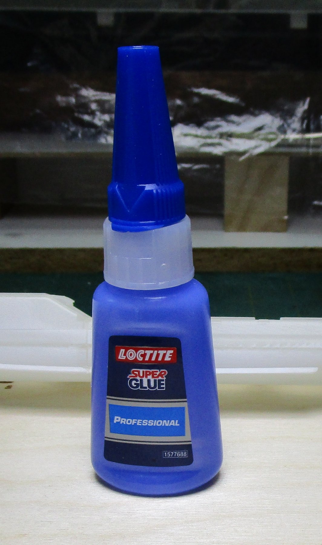
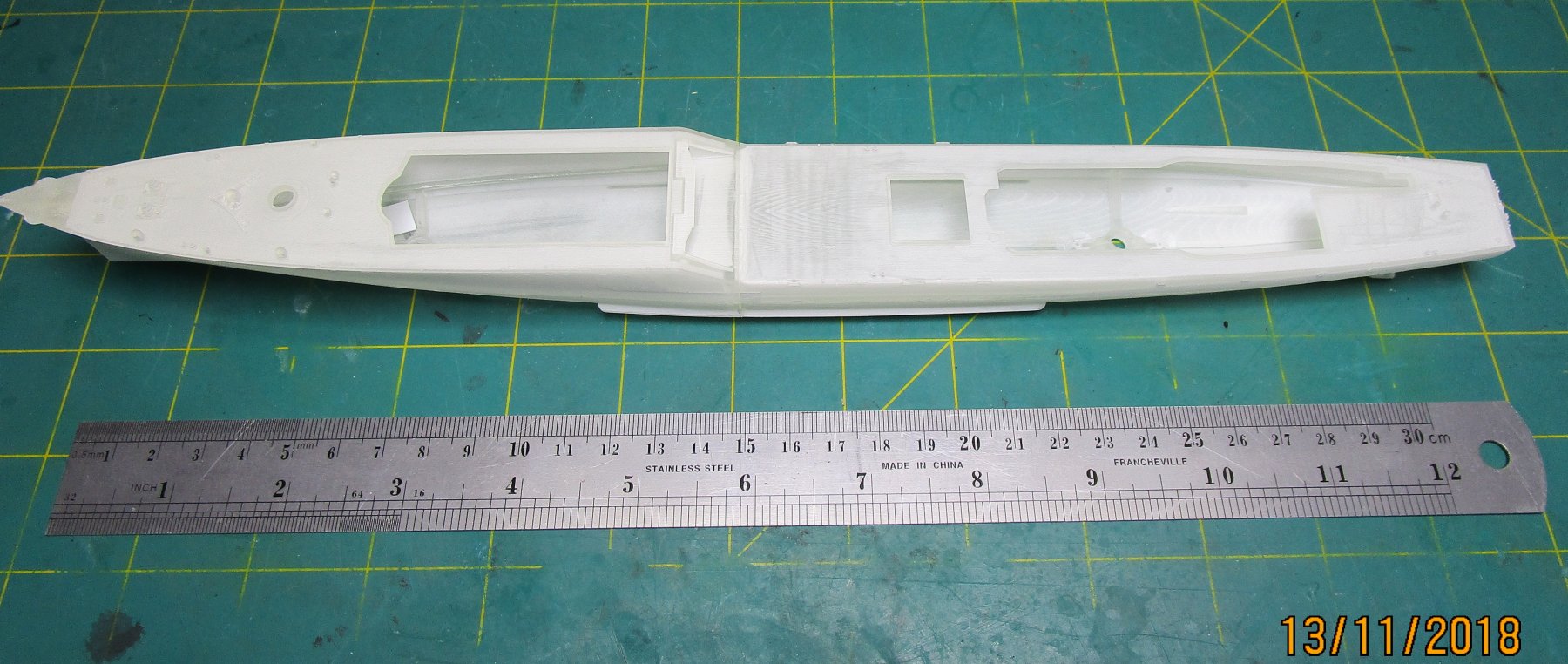
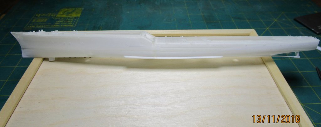
Hull Hi all, after a prolonged delay in starting this build due to many 'life' and other build pressures, i have finally found an opportunity to make a start on this build. I have started assembling the main hull structure which came in 4 pieces. These hull parts fitted together very well once I removed one very minor joint fitting issue (needed to be trimmed/cut away), resulting in very tight joints that will require very little filling and sanding. Bogey is aware of the joint issue now and and will address the master 3D model accordingly. I have yet to fit the rudders and the propeller guards to the hull, but I have drilled out the two holes in the base to accept pedestal style display stands. There are also the propellers and the anchors to fit, but these will be done after painting the hull. I found the only CA that would work with this type of material was Loctite Pro, having tried at least 6 other brands. This was not due to residue or the like as i gave the parts a thorough was in wheel cleaning solution using a soft toothbrush to give them a gentle brush, then a clean a Ultrasonic bath for 4 minutes before rinsing and then air drying in the sun (which also helped to set the parts as they need UV to harden them). Initially I was put off with the parts appearing to get a white frosted coating but apparently this is normal and does not interfere with paint adhesion. Extreme care is needed when handling the parts as this material is very brittle but it sure does show fine detail very well. Not so evident n the attached photos but they will pop when the undercoat is applied. cheers Pat


-
Thanks for the technique Rob, at some stage may be useful to collate these into a single document and put them on the database? Sorry, not trying to create even more work for you, but this is an interesting technique worth preserving. cheers Pat
- 1,208 replies
-
- 1
-
-
- great republic
- clipper
- (and 1 more)
-
Exemplary work as usual Michael; looks great. Only three goes, you must be a master I usually need many more. cheers Pat
-
Hi Dashi, the mentions of the Plane Table above set me looking back through your recent posts and I must admit I missed this. That is a very interesting interpretation of the tiller 'bridge' and I think you have arrived at a very creditable representation. From a navigation and Survery perspective alone, Cook would have need some sort of work area to achieve the high standard (and accuracy) of his surveying. I had given that some thought during my build but did not put in the same level of effort you have. Congratulations: I think this idea is worth much further discussion in an academic study. Your solution also makes better sense of that log entry about a bridge over the tiller. In the past this has been interpreted literally; that is, a means of crossing from one side to the other. Your interpretation provides for the other sense also, that of a 'bridge' as we know it in modern ships; while also providing a very 'workable' surveying station. do you think there would also have been a large chart table? cheers Pat
-
HMCSS Victoria 1855 by BANYAN - 1:72
BANYAN replied to BANYAN's topic in - Build logs for subjects built 1851 - 1900
Hi Steve, thanks for the compliment and the photos. That does look like insect damage; a pity as the sails look good otherwise (shape etc0 but yep they have browned a little. too much. cheers Pat- 1,013 replies
-
- 3
-
-
- gun dispatch vessel
- victoria
- (and 2 more)
-
Ploughing ahead now Rob; looking very good. cheers Pat
- 1,208 replies
-
- 2
-
-
- great republic
- clipper
- (and 1 more)
-
Nice update Denis; she's coming along very nicely - glad you found some room on the tabletop to progress her. cheers Pat
-
Hi Rod, mate I used truss pendants and slings for the lower yards, and parrels above that (as per Steel) as pointed out by Dashi. Looking good so far mate. cheers Pat
- 108 replies
-
- 2
-
-
- endeavour
- caldercraft
- (and 1 more)
-
Thanks Jason, the capstan turned out great. A mate drew up the one I needed in a #D programme and we have also just had it printed at shapeways. I think we used ultra high definition plastic. I am just assembling my Vampire printed with the same stuff and it gave nice detail - just a cow to clean. What did you use? cheers Pat
-
HMCSS Victoria 1855 by BANYAN - 1:72
BANYAN replied to BANYAN's topic in - Build logs for subjects built 1851 - 1900
Thanks for looking in and kind remarks Dashi; appreciated. The log has not been updated in a while but some updates are not too far away. i have been busy researching and preparing drawings for some PE (Rigmaiden Lanyards and the like). cheers Pat- 1,013 replies
-
- 4
-
-
- gun dispatch vessel
- victoria
- (and 2 more)
-
Some very nice detail in that work Jason. Did you carve/make your capstan from scratch as the detail of the pawls etc is very well defined and consistent. cheers Pat