Gregory
-
Posts
3,174 -
Joined
-
Last visited


-
 Gregory reacted to a post in a topic:
Syren Ship Model Company News, Updates and Info.....(part 2)
Gregory reacted to a post in a topic:
Syren Ship Model Company News, Updates and Info.....(part 2)
-
DARIVS ARCHITECTVS reacted to a post in a topic:
Deck planking
-
Gregory reacted to a post in a topic:
HMS Victory by ECK - OcCre - 1/87
-
Gregory reacted to a post in a topic:
HMS RESOLUTION 1667 by KarenM - 1:48
-

Deck planking
Gregory replied to Charlie pal's topic in Building, Framing, Planking and plating a ships hull and deck
What era did you have in mind? Circular saws were not common until the early 19th century, but ( water ) powered vertical blades have been around since the 13th century in Europe. AI tells me: ( So, may need to be fact checked ) -
Gregory reacted to a post in a topic:
Deck planking
-
jerome reacted to a post in a topic:
Which is the oldest book on shipmodelling?
-
Gregory reacted to a post in a topic:
HMS Perseus by Thukydides - 1:64 - POB - Sphinx Class 6th Rate
-
Gregory reacted to a post in a topic:
Nail pusher nightmare
-
Gregory reacted to a post in a topic:
Lady Nelson by Danstream - Amati/Victory Models - 1:64 scale
-
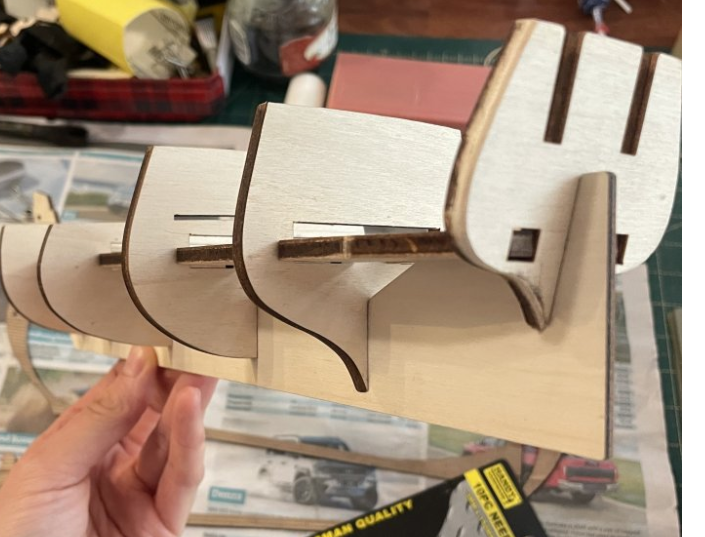
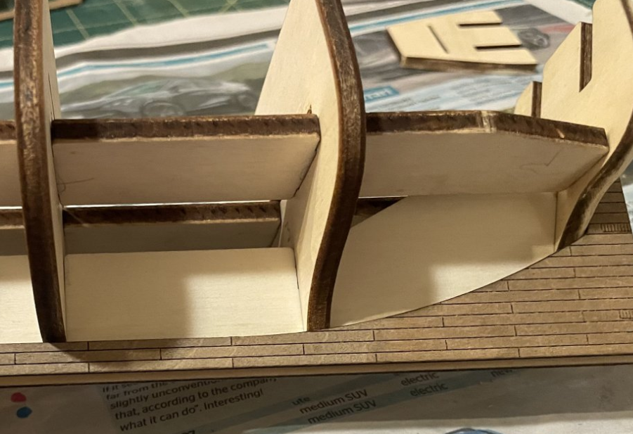
If the bulkheads are square, I wouldn't worry about it. The backbone being higher in front of the bulkheads is because of the slope of the deck. I would sand them down to accommodate the slope.
-
Ryland Craze reacted to a post in a topic:
My Rope Making Machine ( Rope Walk )
-
Tumblehome reacted to a post in a topic:
My Rope Making Machine ( Rope Walk )
-
Nunnehi (Don) reacted to a post in a topic:
My Rope Making Machine ( Rope Walk )
-
Nunnehi (Don) reacted to a post in a topic:
My Rope Making Machine ( Rope Walk )
-
JerryTodd reacted to a post in a topic:
My Rope Making Machine ( Rope Walk )
-
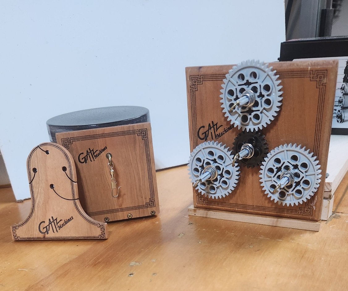
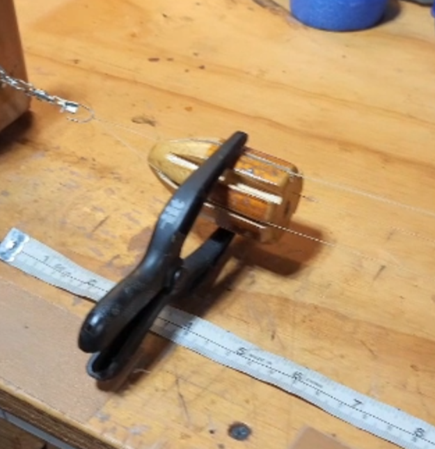
Here's an update after this discussion prompted me to refine my machine a little bit. Here are the elements of a machine that I would consider selling if I find there is any interest. It would be (essentially ) fully assembled and very competitively priced compared to other machines out there. A change I have made in the design is the piece on the left that I call the "keeper". I haven't seen this before, so I think it is original in form, but serves the same purpose as the "topper", explained above. The principle of the topper is incorporated in traditional full size machines, and serves to keep the strands separated until there is enough tension for them to twist into a finely made rope. It requires some management on a modeling scale because it tends to roll or fall out as the process evolves; thus the reason for the clamp as shown.\ I was thinking about providing a topper with a clamp in my "for sale" machine, but my " Keeper " does away with the clamp. My 'keeper' manages to get the job done without the clamp, and only requires a little fiddling with as the job progresses. I am working on a video to demonstrate, but the operation is pretty much the same as shown earlier.
-
AON reacted to a post in a topic:
Ring Bolts
-
BenD reacted to a post in a topic:
Rigging scale for 1/85 Frigate
-
Edge-set deck planking
Gregory replied to Hakai43's topic in Building, Framing, Planking and plating a ships hull and deck
Not sure what you are calling edge setting. Haven't heard the term before. Your drawing looks like accepted practice. -
If you are thinking about using https://www.meshy.ai/pricing Meshy Paid version, they are having 50% off for a limited time. The paid version gives you unlimited downloads of Meshy 6 content.
-
Capstan 'Out of Stock'! Looks like a hit!
-
kit review 1:48 La Renommée 1744 - CAF Model
Gregory replied to James H's topic in REVIEWS: Model kits
Just curios about why some parts are best rendered via CNC rather than laser?- 20 replies
-
- 1
-
-
- cafmodel
- la renommee
- (and 1 more)
-
That is correct..
-
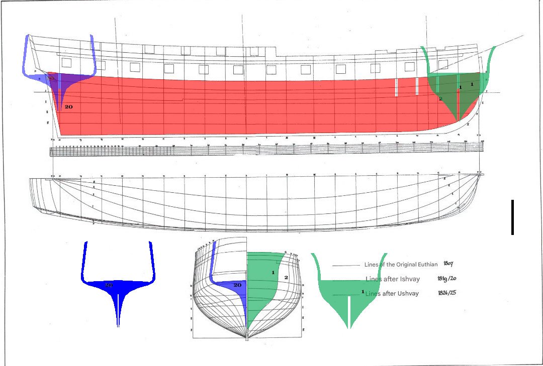
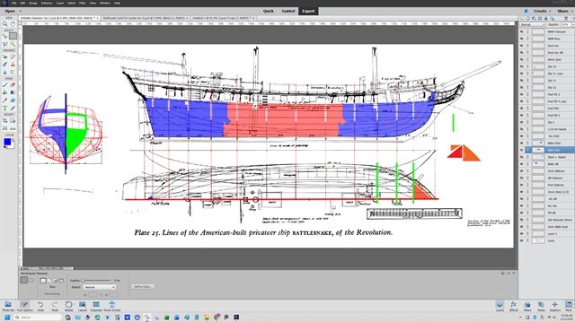
@Adnannur What you propose represents a task almost as challenging as building the model itself and doesn't lend itself to a simple explanation. This is a task that kit manufacturers undertake, and it is a very costly part of kit development, and why scratch building is far more challenging than kit building. At the beginning of my Rattlesnake build, I included a little bit of my drafting workflow. I have taken your drawing and shown some basic, simplified steps. The backbone is defined by the area inside the keel, stem, stern post and gun deck. If you wish to show the camber/curve of the gun deck you will need another line that is slightly lower than the mid line of the deck. A line not shown on your drawing. The 'Stations' shown in the bottom of your drawing, define the shape of the hull. Your drawing has 20. Most kits may have half that number. As in your drawing, the stations looking aft are shown on the right, and looking forward from the stern on the left. The shape of the stations define the bulkheads of the skeleton. Since the stations drawing shows only half, you mirror that to get the full shape. The slots are determined by the thickness of your building material. If it is 1/4" plywood, then the slots need to be 1/4". I have shown only a few slots for simplification. There will be other challenges, such as framing the gunports and establishing the quarterdeck and forecastle. Kit manufacturers usually move the stations as needed so they do not intersect a gun port or other opening, because it would otherwise complicate building the model. Moving the stations may require adjusting their shape to maintain the correct shape of the hull. There are drawings available that show more detail such as this drawing of Enterprize of 1770. I assume you have drawing or CAD software that you will use. I use an older version of Photoshop Elements, that I find more than adequate for my purposes. Layer support is important. On the right side of my work screen you will see all the layers I am using at this stage of my work with only 2 of 12 bulkheads. I hope this will give you an idea of what you will need to develop a skeleton from a line drawing.
-
There is some limited milled wood available on Amazon. Mostly basswood.
-
What type/form are you looking for? For milled wood there is HobbyMill.EU, one of the MSW sponsors.
-
Dziadeczek's comment is one of the best you will get. While you are looking to get it right, you might note that blocks, being part of a tackle would not have been stropped to an eyebolt on the deck like shown in your instructions. There would be a hook on the block and it would hook into the eyebolt. You will see how to strop a block with a hook in the tutorial Dziadeczek posted. From the tutorial.
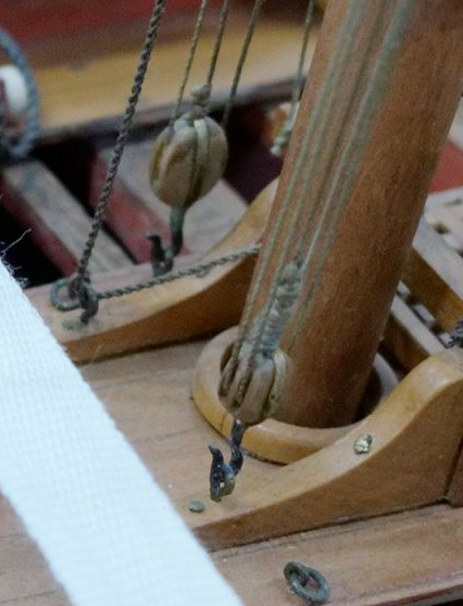
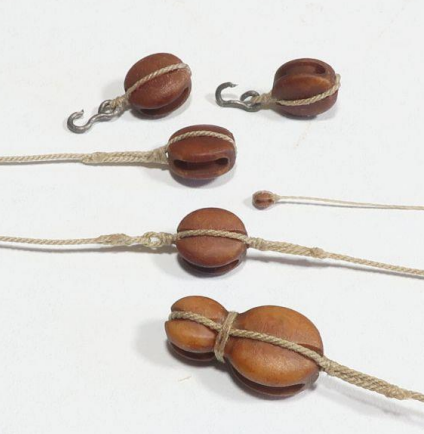
-
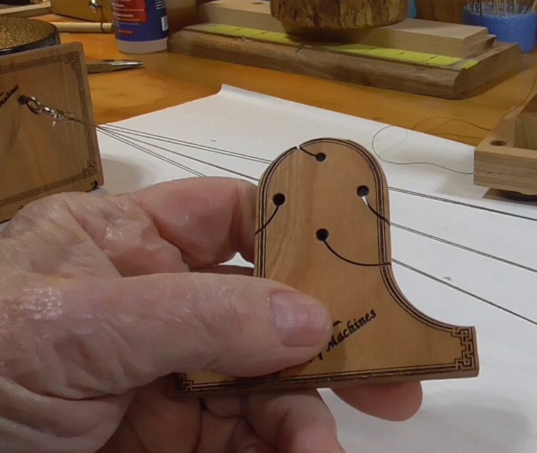
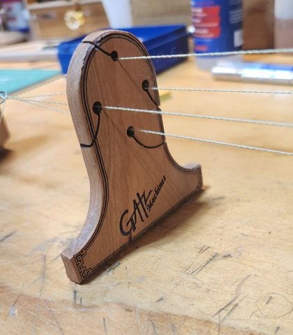
Strange. The 'pointy' one looks too low here. ..but looks OK here.
-
jig for making uniform footrope stirrups
Gregory replied to Lost and Confused's topic in Masting, rigging and sails
I'm looking for a jig, but meanwhile, if you make the stirrups in a uniform manner, all else falls into place.. Here is a search for "stirrups".. Here are a couple of examples. -
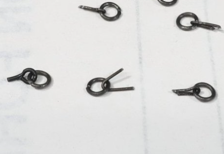
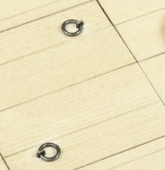
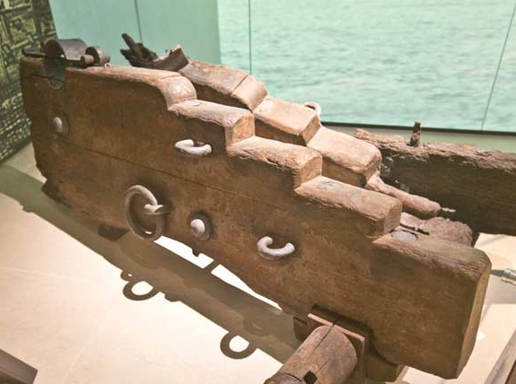
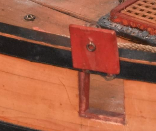
You should get a lot of feedback on this, but I was particularly taken by a method Chuck demonstrated with Speedwell. Instead of making eyebolts that look like the little jewelry eyelets provided with most kits, one simply makes a U-shape from the wire being used. The following is clipped from the post by Chuck. You then counter sink this "eyebolt" into your work and it looks very realistic. The "hole" you sink it into needs to be a little oval shaped instead of round. I have since observed this feature on contemporary models and artifacts. Here it is on a salvaged gun carriage. Here is an example from a contemporary model. It is really effective for small applications like the gun port lid.