


BETAQDAVE
-
Posts
5,367 -
Joined
-
Last visited
Content Type
Profiles
Forums
Gallery
Events
Posts posted by BETAQDAVE
-
-
The metal fife rails that came with the kit shown below didn’t look much better than the kit supplied anchor so I decided to see if I could do better job with wood.

They also differed both, from the detail drawings on the plans and the ones shown in Chucks’ practicum shown here.
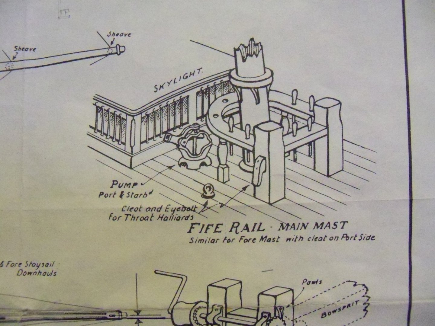
You can see that the cross bar between the posts and the side half cleat are higher than the fife rail on Chucks’, as opposed to them being even on my kit and the details. The posts are taller than mine, and the spindles are much thicker. The belaying pins included with the kit were much too short to project below the rail which would not allow the belayed lines to be tied off.
The first step was to rip a 3/32” X 3/32” maple strip about 6” long for the post material. I marked one face for the cuts and using my Micro Miter Box with the ultra-fine toothed double-edge razor blade once again, I cut it into six sticks about 1” long. In this case, the final length was 7/16”, leaving 9/16” left over to hang onto during the machining.
Since this was another process of making each piece an exact duplicate of the others, I utilized the adjustable stop for every cut. The stop was not reset until that particular cut was repeated on every piece. The first cuts were made 3/64” deep and 7/64” down from the top of the post on two adjacent sides. The next two cuts were duplicated 1/16” below the first cuts.
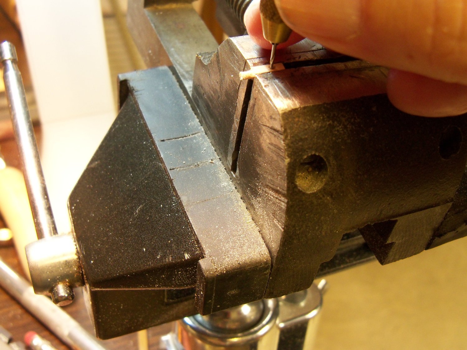
Clamping each post in my machinist vise, I carved out a 3/64” deep notch between those two adjacent sides with a fine file between the first two cuts for holding the fife rail. Returning to the Miter Box, a very shallow cut was made on all four sides of the stick 21/64” down from the top of the post to mark the overall height of the post above the deck. 7/64” below that cut, the post was finally cut loose from the stick.
Now each post was clamped in my vise with the 7/64” bottom left exposed. Once again I filed a round peg with files and sanding sticks for insertion into the deck. Here is one of the resulting fife rail posts.
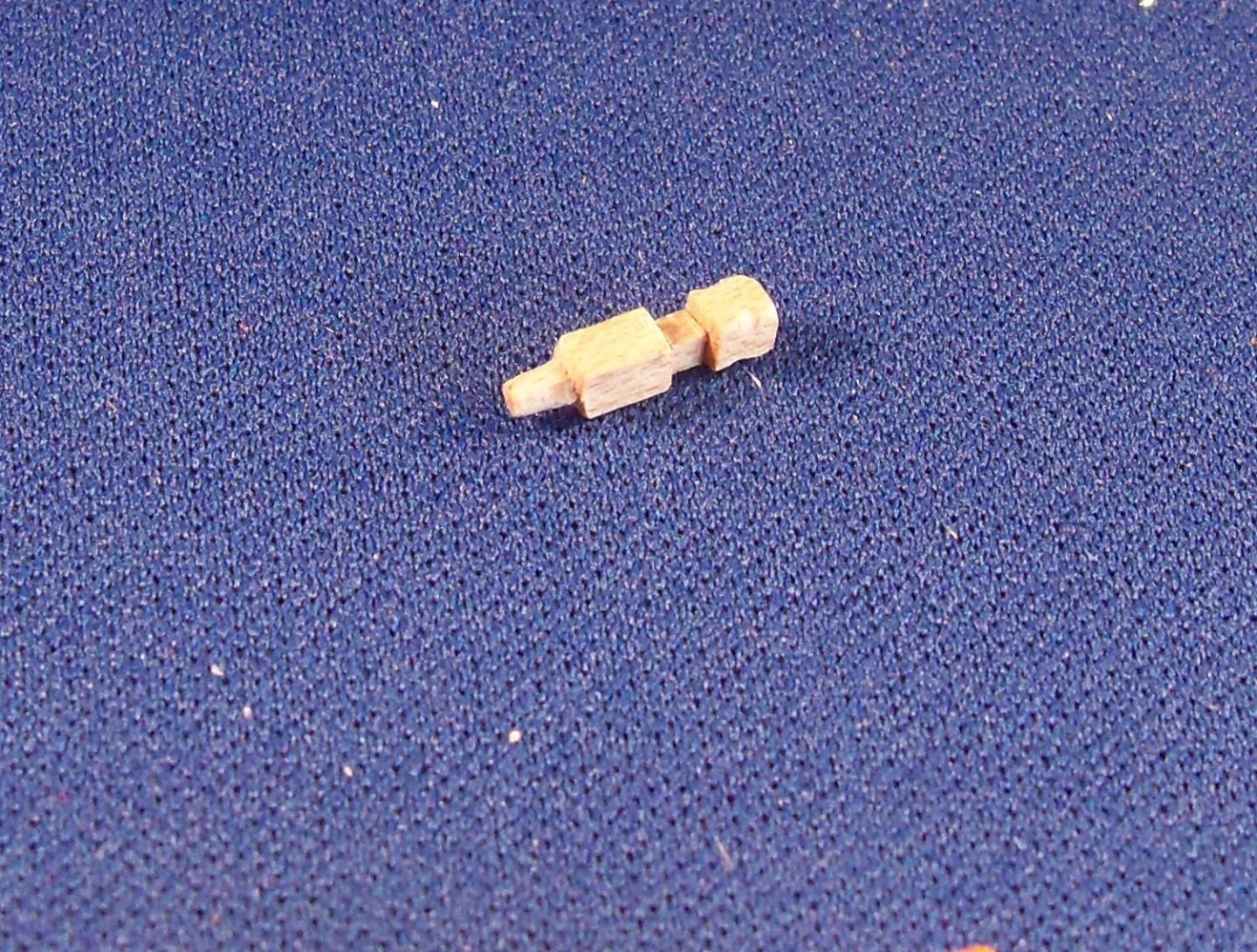
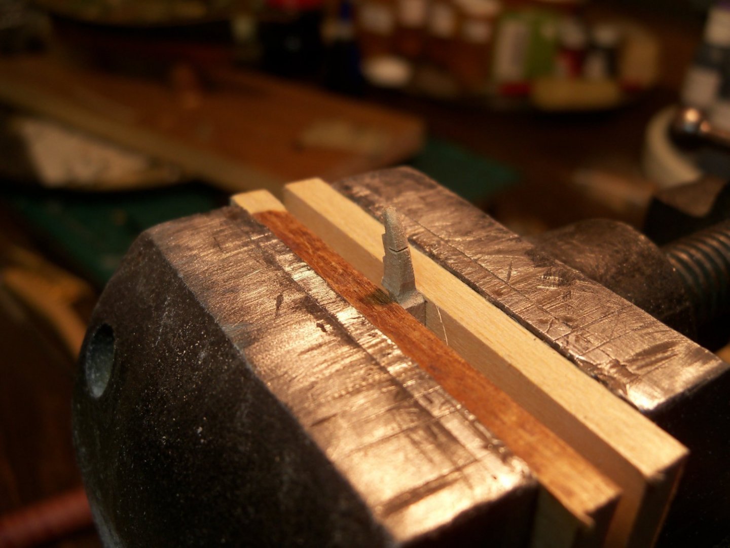
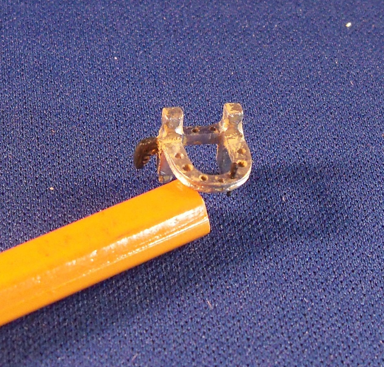
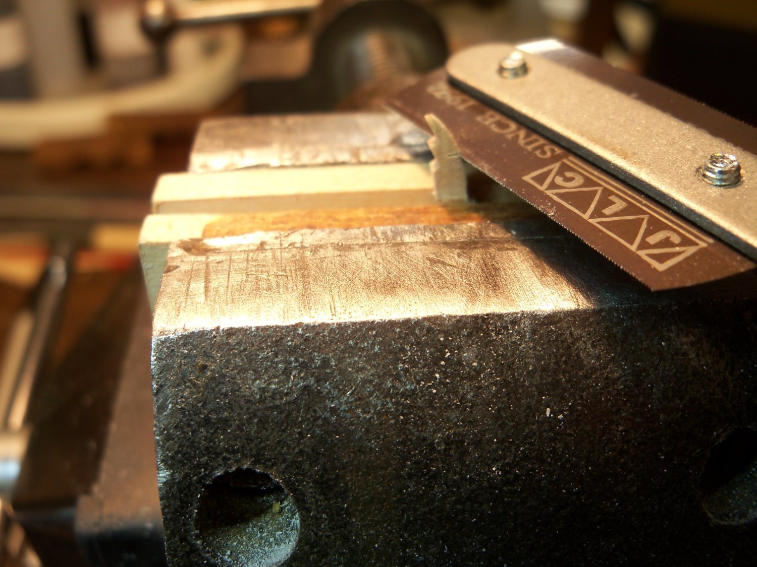
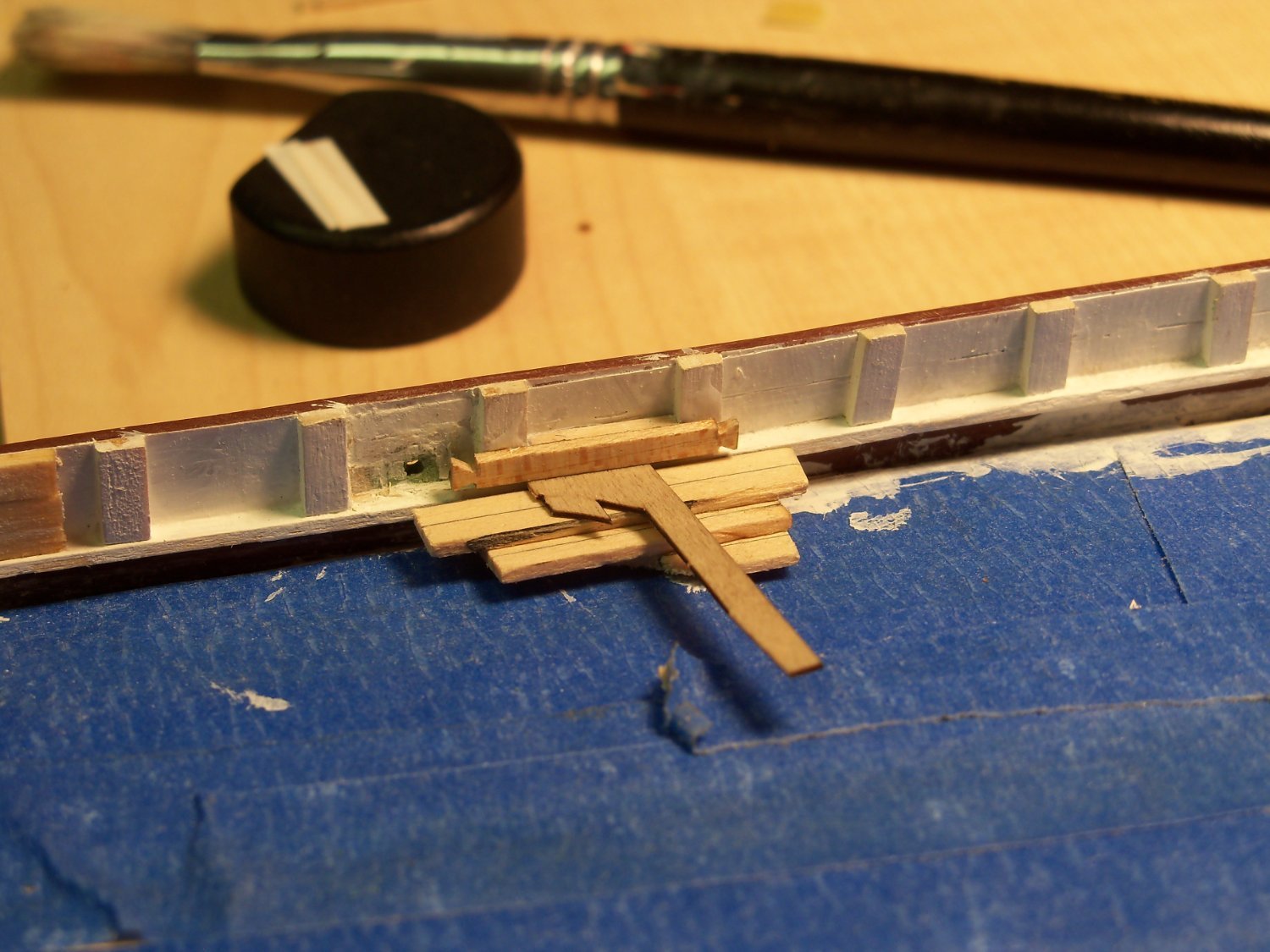
Then I also needed to make two throat halliard half cleats to be attached to the posts. There is one on the starboard side of the main fife rail and one on the port side of the fore fife rail. I decided to carve these from wood, since cutting one of the kits’ metal ones in half would still be over-sized. These cleats are a prime example of fabricating extremely tiny parts, (1/16” wide X 5/64” high X 5/32” long) so I will provide some photos of the process here.
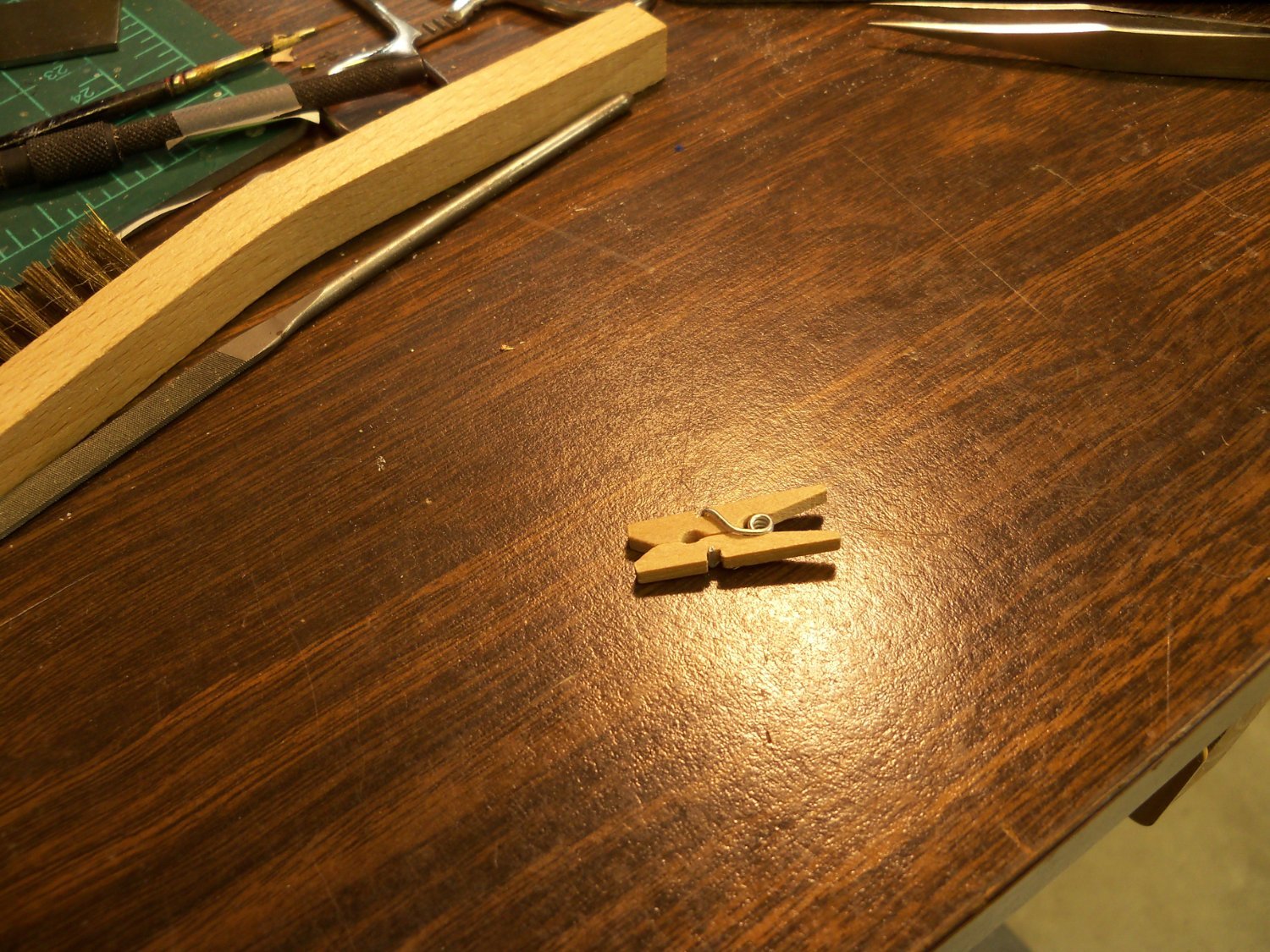
To start with, I sacrificed these hardwood clothes pins for the material as shown below.

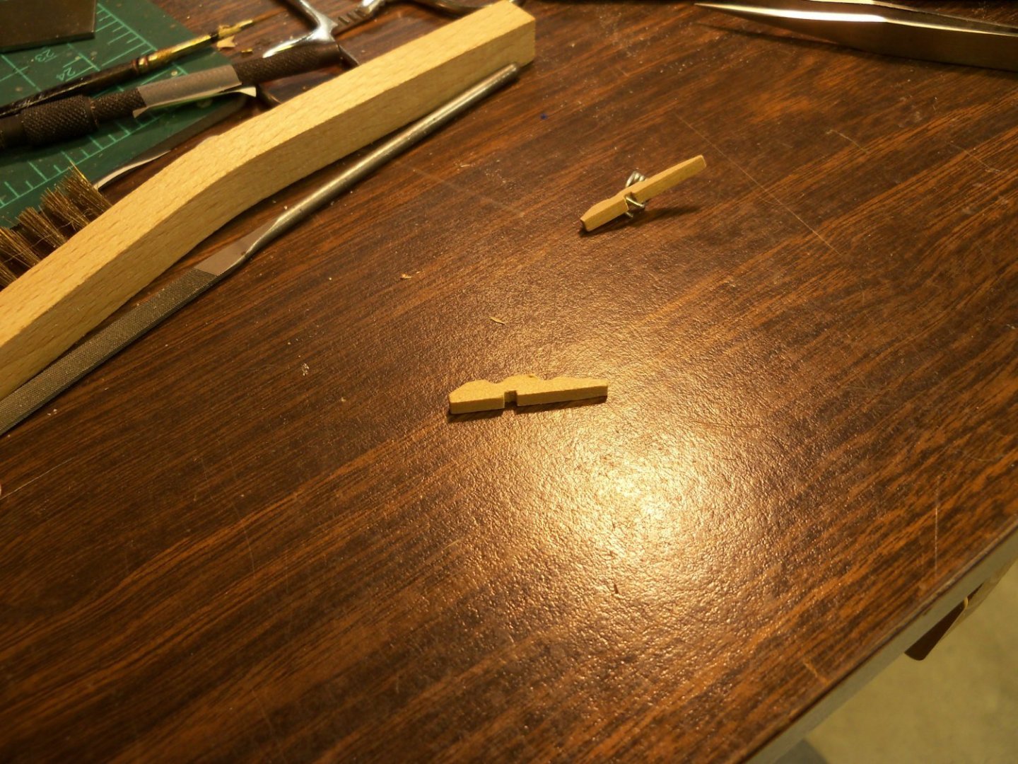
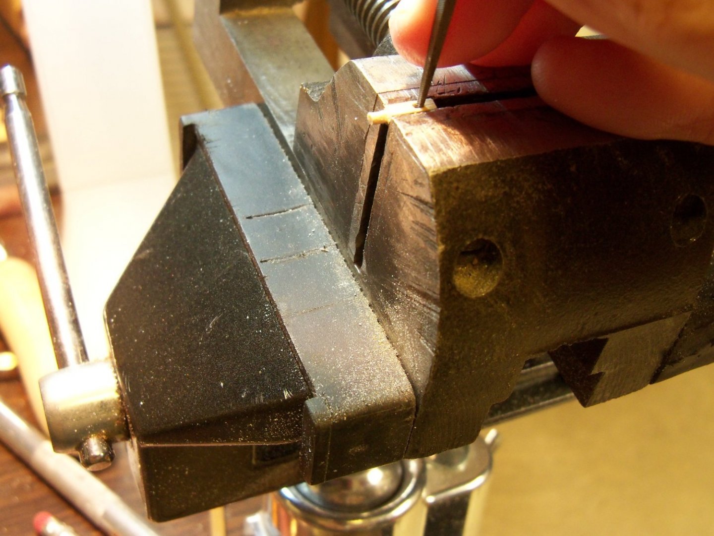
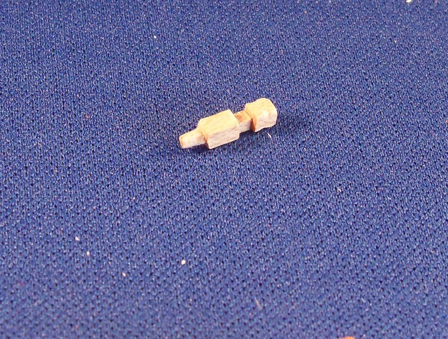
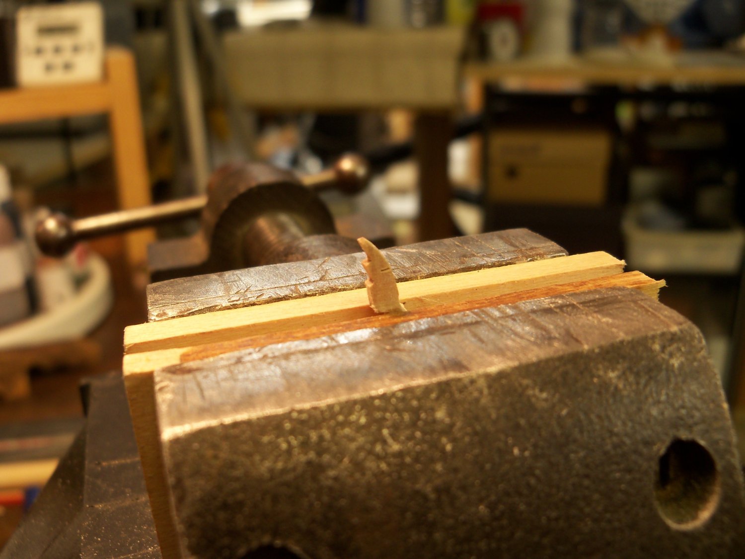
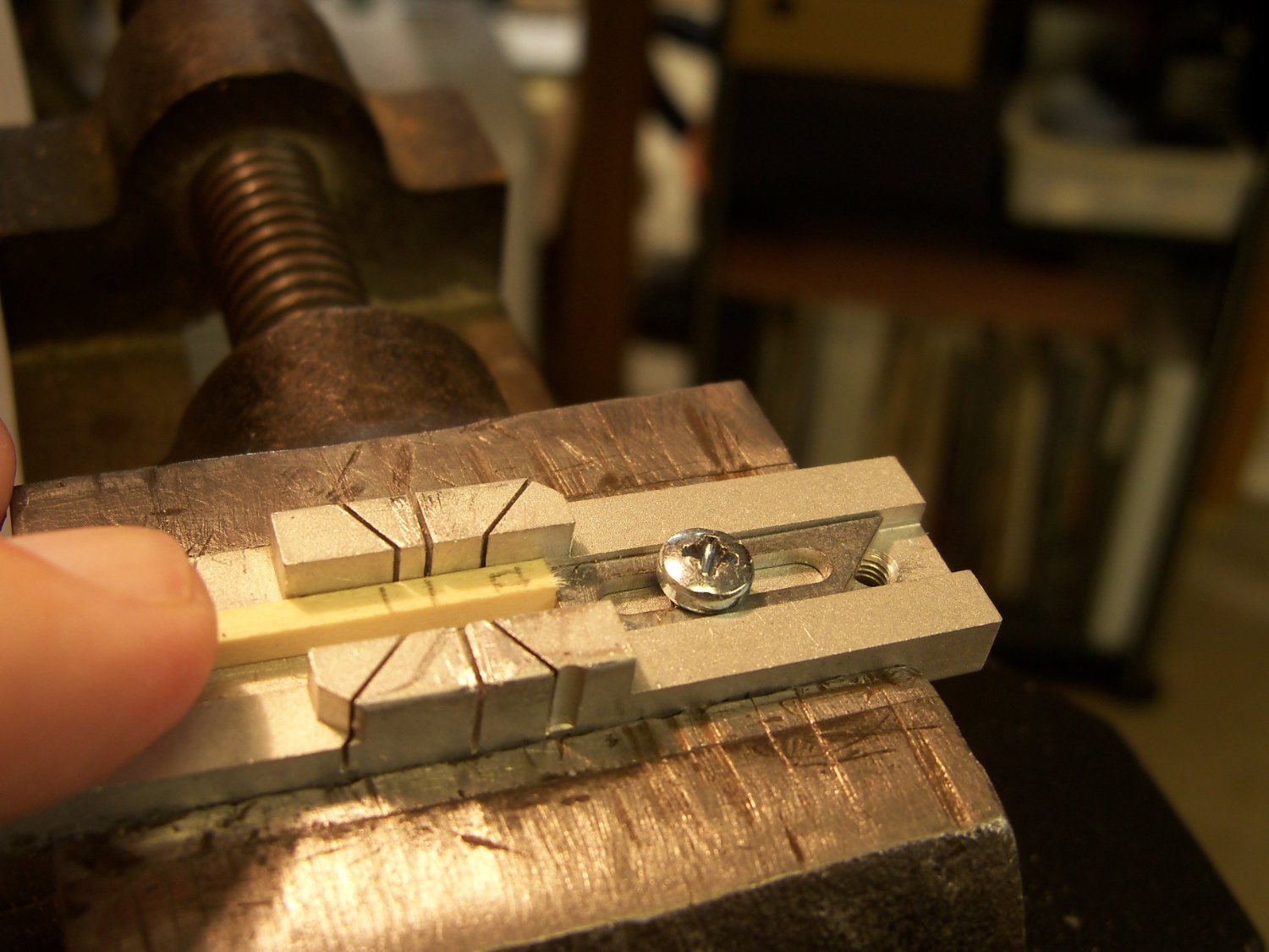
The long skinny portion was clamped in my vice, leaving the short fat end exposed. Using sanding sticks and files, the top and bottom were shaped.

Once the top and bottom of the cleat were shaped, the sides of the cleat were thinned down and tapered to the final profile.
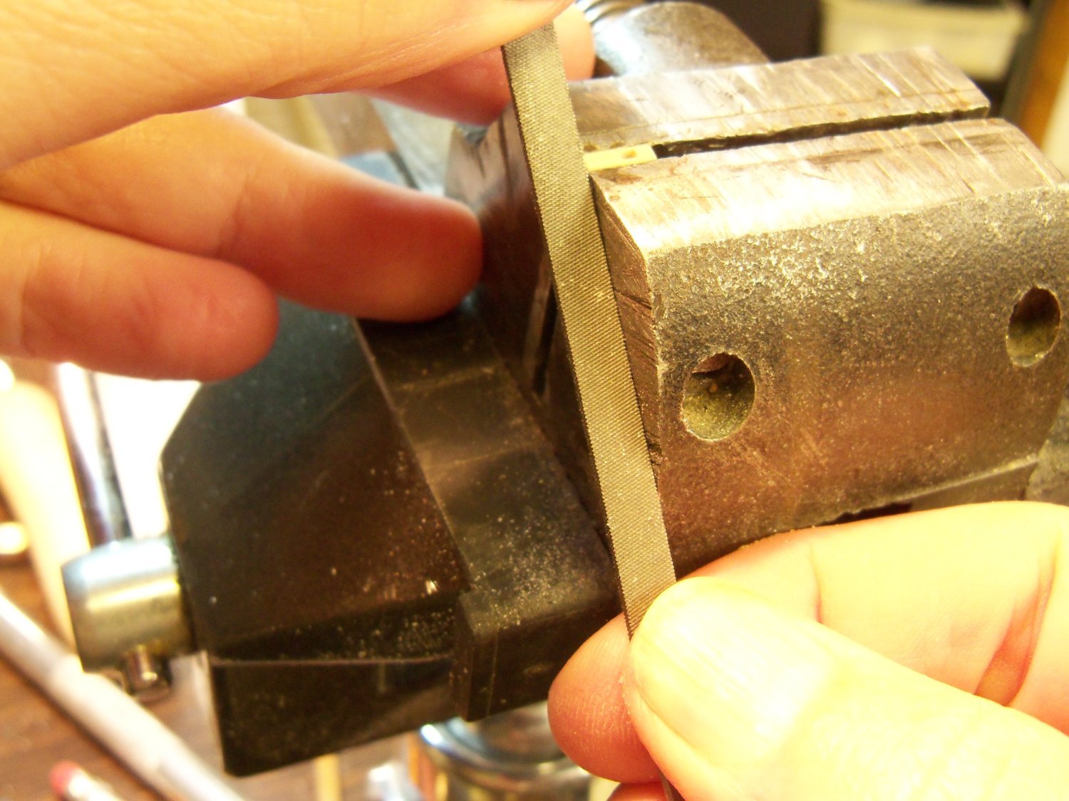
Now that the main portion of the cleat was finished I released it from the handle with that razor toothed hand saw and repeated the process for the other cleat.

The cleats will be painted iron black and glued to the appropriate fife rail post.
-
5 hours ago, shipman said:
. A Pica is 1/6th of an inch.
That's opposed to using elite and pica typewriters, where elite was 12 characters per inch and pica was 10. I always thought that 1/6th scale was a peculiar system of measurement to be used for modeling when I had to build my first model of the Wanderer from the A.J. Fisher plans. I had to make a custom ruler just to build it. Luckily, they had the fittings kit that matched.

-
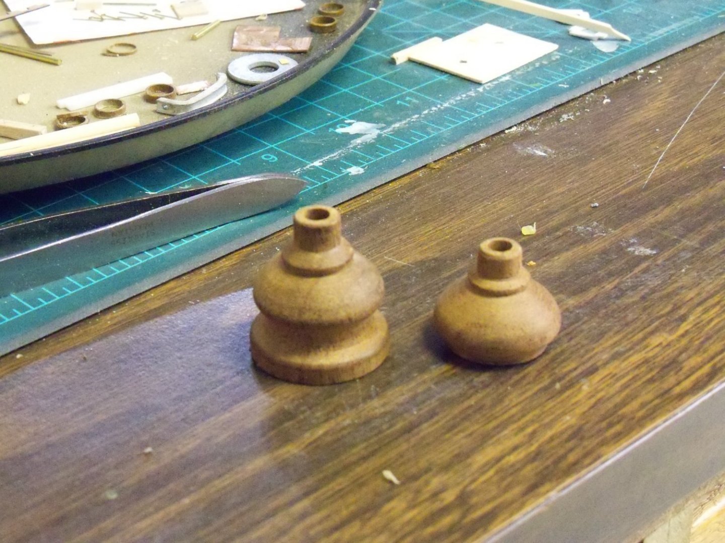
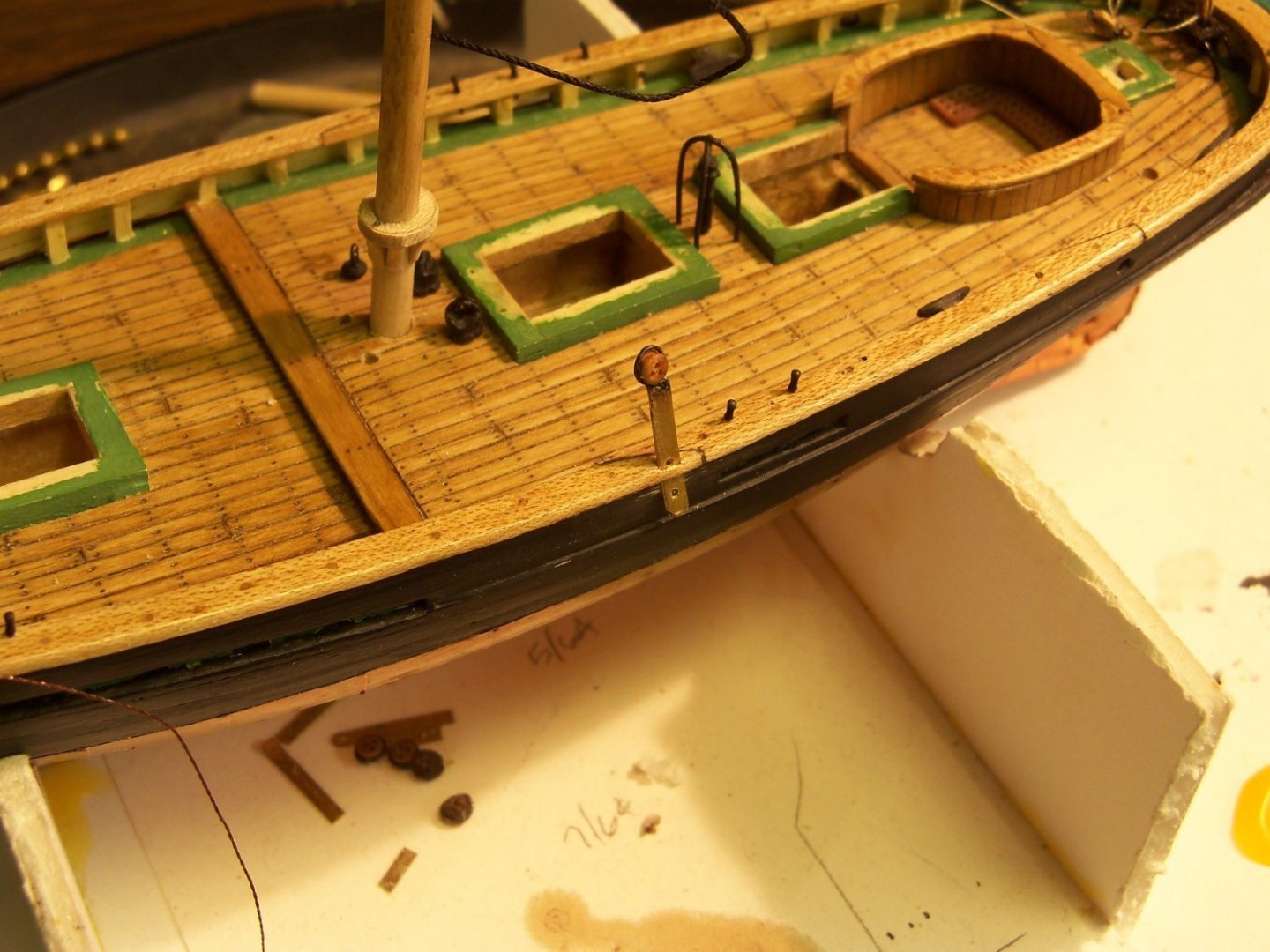
I decided to tackle the bollards next since they seemed to be a simpler project. The ones I made previously appeared over-sized when placed on the model, so these were now discarded. Originally, two posts were made with a rectangular cross bar and the other two were without. This time, all four will have the cross bar. Since these posts wouldn’t be under any strain once installed, I just used six 2” lengths of 3/32” square basswood stock for the new posts. (I’ve learned the hard way, that small pieces need to be cut overlong to leave a “handle” until cutting the piece loose and to make extras.) To be uniform, I made extensive use of the stop on the Micro Miter Box below for all of the cuts and made the same cut on each piece before moving on to the next piece.

On the face of the first post, marks were drawn at the locations of the top, bottom and sides of the mortise for the cross bar, the height above the deck and the overall length of the piece to serve as a pattern. The mortise is centered and 1/16” down from the top of the post. The mark for the deck is 1/4” below the top of the post and the overall length is 7/16”. The cross bar is made from 1/32” X 1/16” maple and is cut overlong at 1”.
The first cut in the post was a shallow one all the way around the post at the top of the deck mark to limit the filing of the peg. The next cut was to separate the post from the rest of the stick. The post was set in the vise with the shallow cut up against edge of the vise as shown below to allow the use of a flat file to form the peg at the bottom that will be set into the deck.

The mortise was formed next by putting the post in the vice to prevent it from splitting while forming the hole. Two side by side 1/32” through holes were drilled first with a pin vice.

Then I used my smallest square file to square the corners of the mortise until the cross bar was a tight fit.
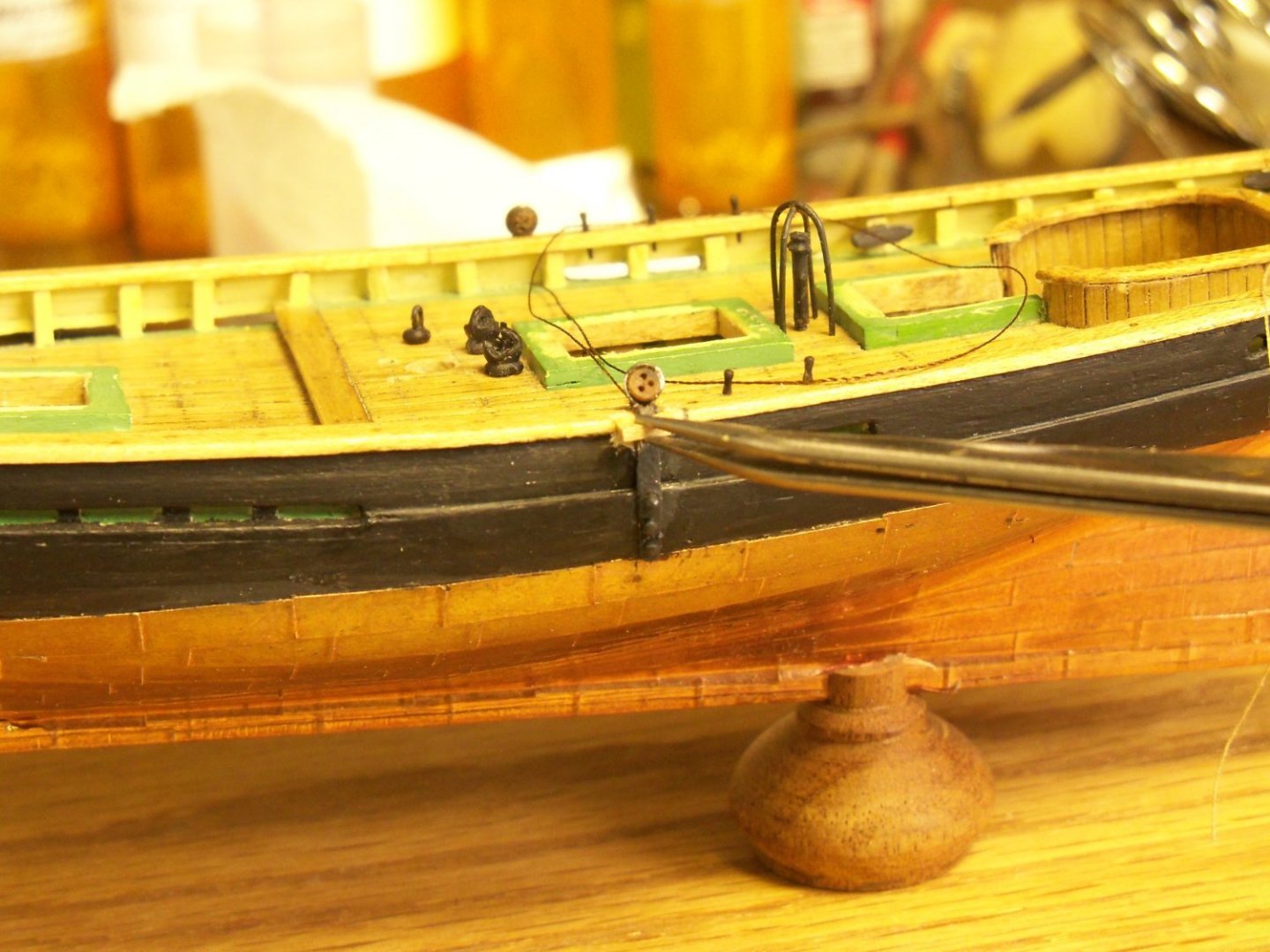
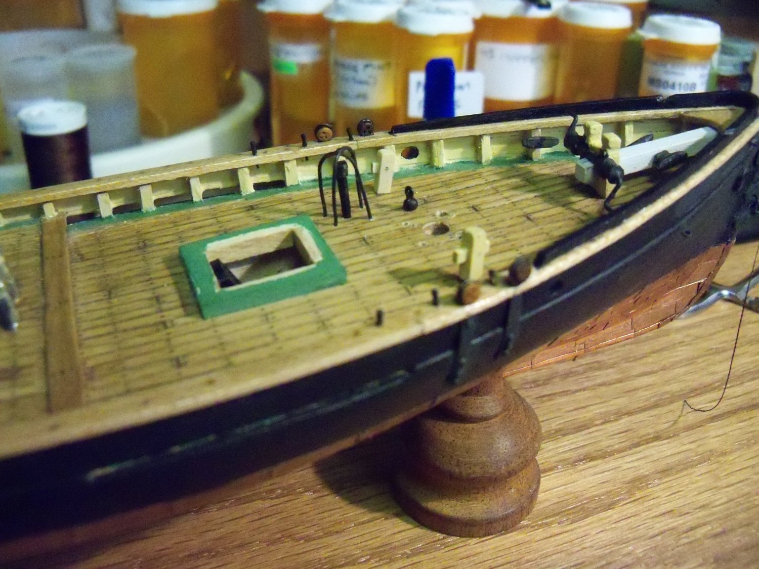
The cross bar was inserted into the mortise until it projected 1/16” from the opposite face of the bollard. The remaining end of the cross bar was also trimmed off leaving a 1/16” projection with a fine sanding disc mounted in my cordless Dremel tool. Once the cross bar was in place, I used a #78 bit to drill through the post and the bar joint. I sliced a tiny sliver of wood and inserted it through the hole to lock the joint. Here are photos of the four bollards put in place on the model.
There was some thought of putting a copper cap on the tops of the bollards again, but after a little more research I found that it was not all that common a practice on pilot boats. Besides that, I would have to put a cap on all the vertical posts to be uniform. The completed bollards were sanded, given a light coat of light buff deckhouse and set aside for installation later.
Next on my list is the fife rails.
-
Welcome to the clubs John, both MSW and the Phantom build club. Many of our members have tackled this kit as one of their first wooden ships. Originally I bought this kit as a graduation gift for my uncles son while it was on sale. Unfortunately, (Or maybe fortunately) I discovered by way of my uncle, that he didn’t think that his son would be interested, so we ended up just giving him money instead. Since it had been quite a while since I last built a wooden ship, I decided to tackle it myself.
Chuck Passaro made a build log that pretty much follows the kits’ manual. I would suggest that you read his log first since his guide goes from the beginning to completion of the model. I have deviated quite a bit from his version, but it was mostly to add things that the kits’ manual either over simplified or omitted all together.
My only regret that I have is that I forgot how hard working at this small scale was. I think I would have preferred making it from scratch at 1:64 which would have made all of the tiny parts much easier to handle and add the smaller details, but perhaps I could do that later, if I hang around that long.
At any rate, I continue to soldier on with it and switch over to the Wanderer whenever I feel the need for a little more variety in the hobby. As far my Wanderer build goes, the vast majority of the plastic parts I will be making myself since those parts are inaccurate and/or poorly detailed.
Good luck on your build, and don’t be afraid to deviate as you see fit.
- Mirabell61 and Ryland Craze
-
 2
2
-
I've found conflicting information on late 19th century timber bollards. While most bollards were simply bare topped timbers, some had metal or leather caps apparently to provide protection from end grain rot. For one example, in the whaling industry there was a large vertical bollard that the cutting in gear was secured to that usually had a metal top applied to it. It may also have served as an anvil for the ships carpenter. Has anyone else come across any info. on this?
- mtaylor and Keith Black
-
2
-
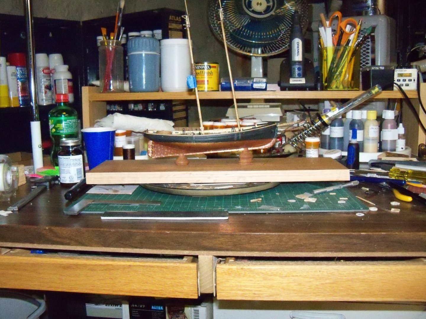
Heading out to my scrap lumber supply in the garage, I pulled out a 15” long piece of 1X8 prefinished oak to rip down to 5” wide for the display base only to discover that my table saw is out of commission right now, since one of the rubber caster wheels had been crushed by the weight of the saw.
 So the band saw had to be used instead. Since the band saw gives me a rougher cut than the table saw, I also had to use a heavy hand plane to smooth it down.
I measured the plan to determine the placement of the support pedestals and marked the location of the holes on the display board. The ends of the board will still need trimming and a rabbet needs to be formed all the way around the board to hold the plexiglass cover, but I will have to do all of that at a later time.
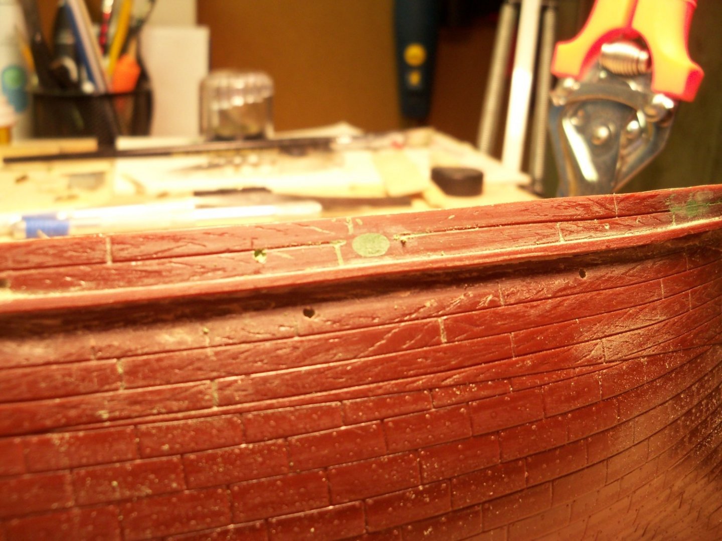
OOPS! I thought things were going too smoothly and I was right. 😢 While handling the hull to temporarily set it upside down on the drill press to drill the mounting holes in the keel, I inadvertently broke out a small section of the port side main cap rail right at the lower mainmast deadeye. So now that’s something else I’ll need to repair after getting the ship mounted.
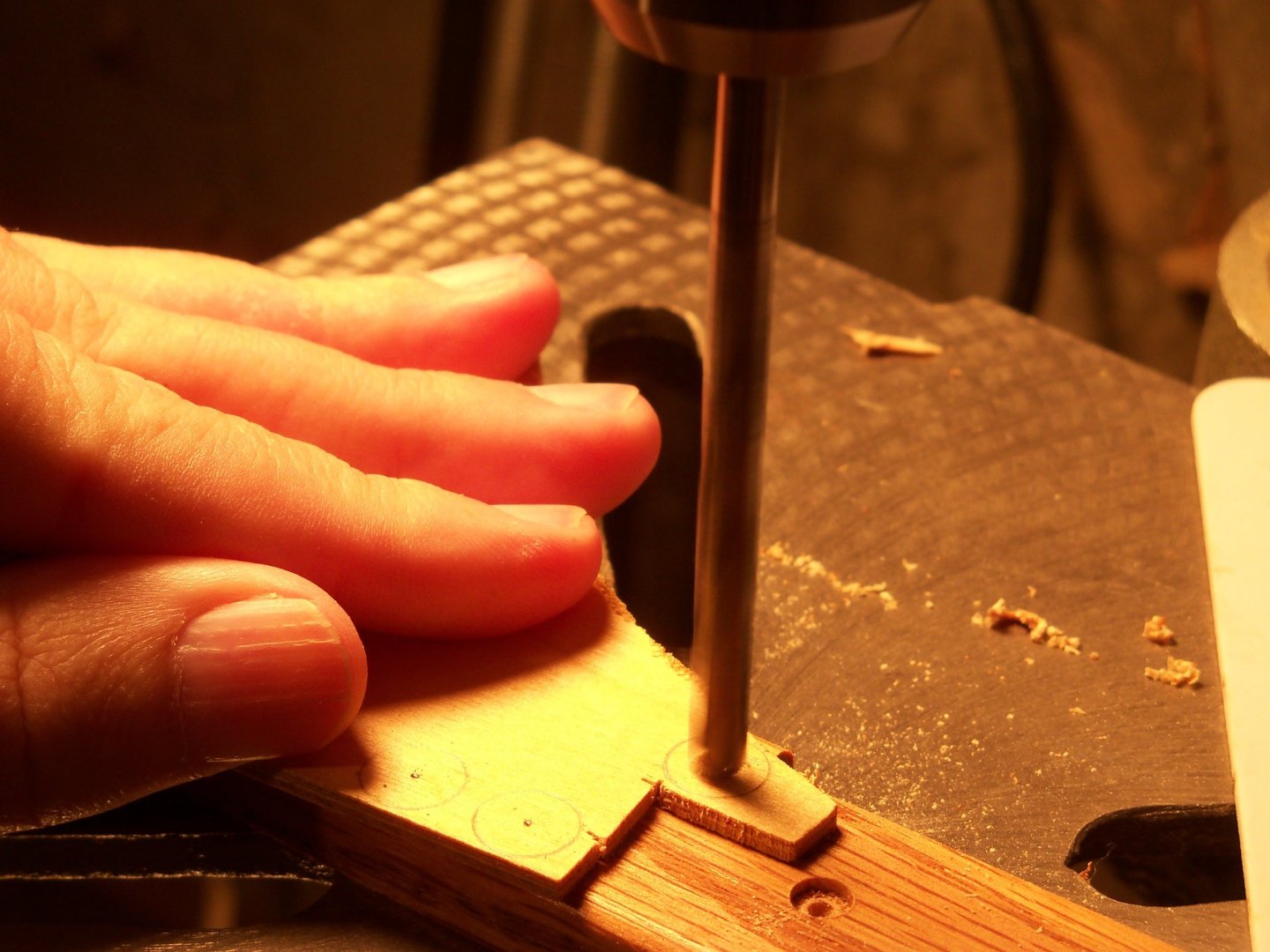
The hull was placed upside down on a piece of plywood with some leveling blocks to make the waterline parallel to the plywood. The positions of the two holes 4.5” apart were then marked on the keel at stations #2.5 and 7. The whole setup was put on the drill press table and maneuvered into position below the drill bit. Very carefully, I drilled the 7/64” holes to the proper depth into the keel with a brad pointed bit while trying to avoid damaging the copper plates.
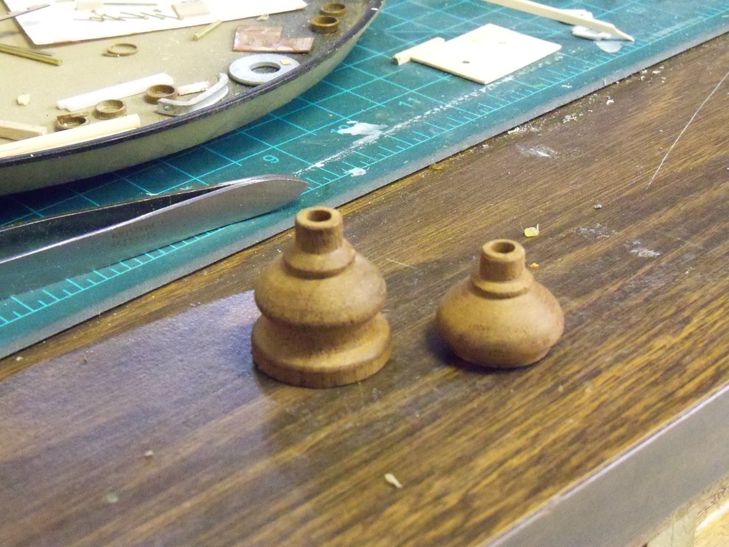
Long ago, I had turned a matching pair of pedestals out of walnut for mounting a plastic WWII warship that ended up being made of brass. Rather than order another set of brass pedestals, I decided to modify the walnut ones to suit the sloped keel of the Phantom.
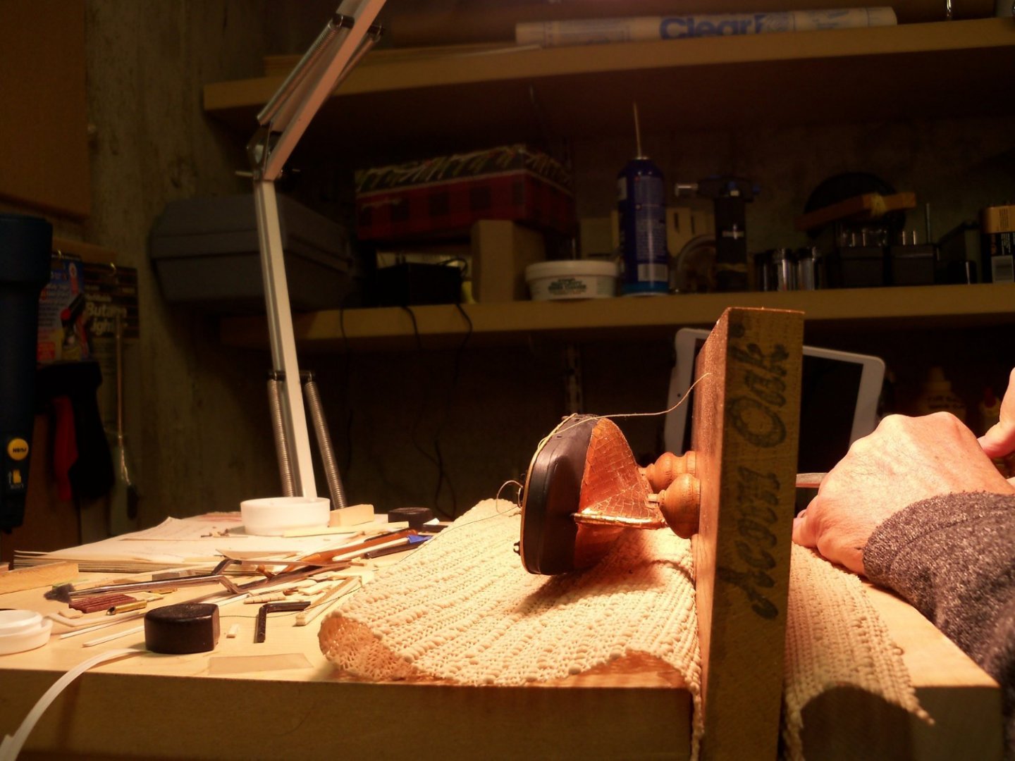
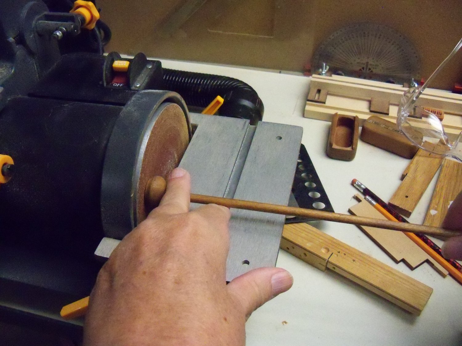
First I measured the required height difference in the two pedestals and put a mark there on the lower portion of the short one. By slipping a tight fitting dowel into the mounting screw hole, I went over to my disc sander and held the dowel perpendicular to the disc as shown below.

I slowly pushed the pedestal into the disc while rotating the dowel until I came to the mark. Here is the modified pedestal next to the original one at this point.
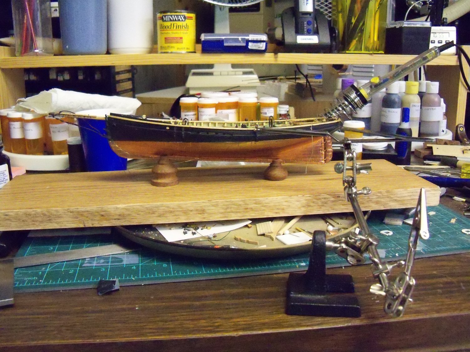
The slots in the tops of the pedestals were cut to fit the width of the copper plated keel and the mounting board was clamped in my padded woodworking vice. Then I laid the model on its side and lined it up with the holes for the screws as shown below.
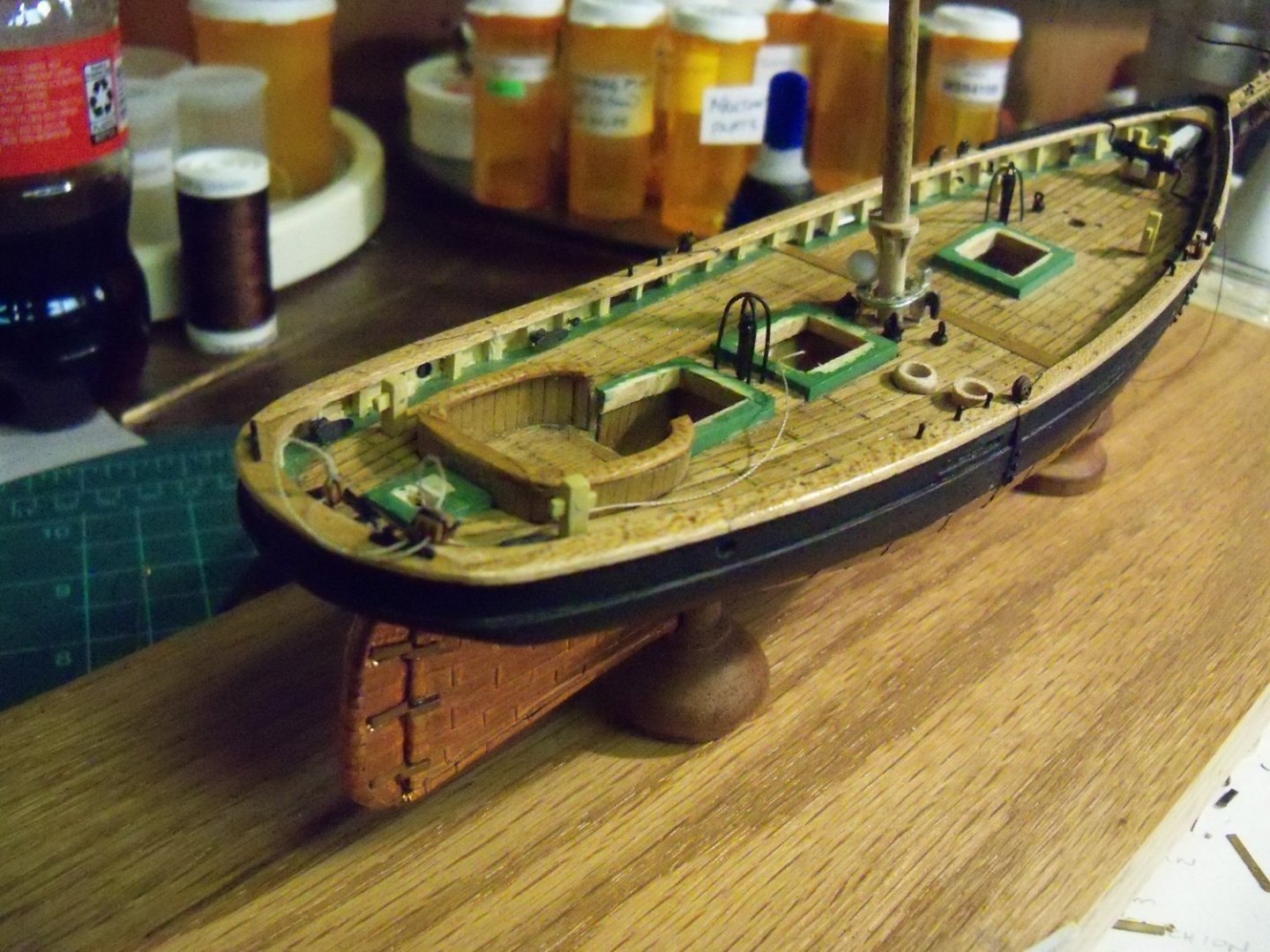
One screw was pushed through the board, the pedestal and into the hole in the keel. Once this one was started, I did the same with the other screw and alternated from one to the other until both were secured. I inserted the masts just to be sure it was vertical and here she is temporarily mounted on the board.
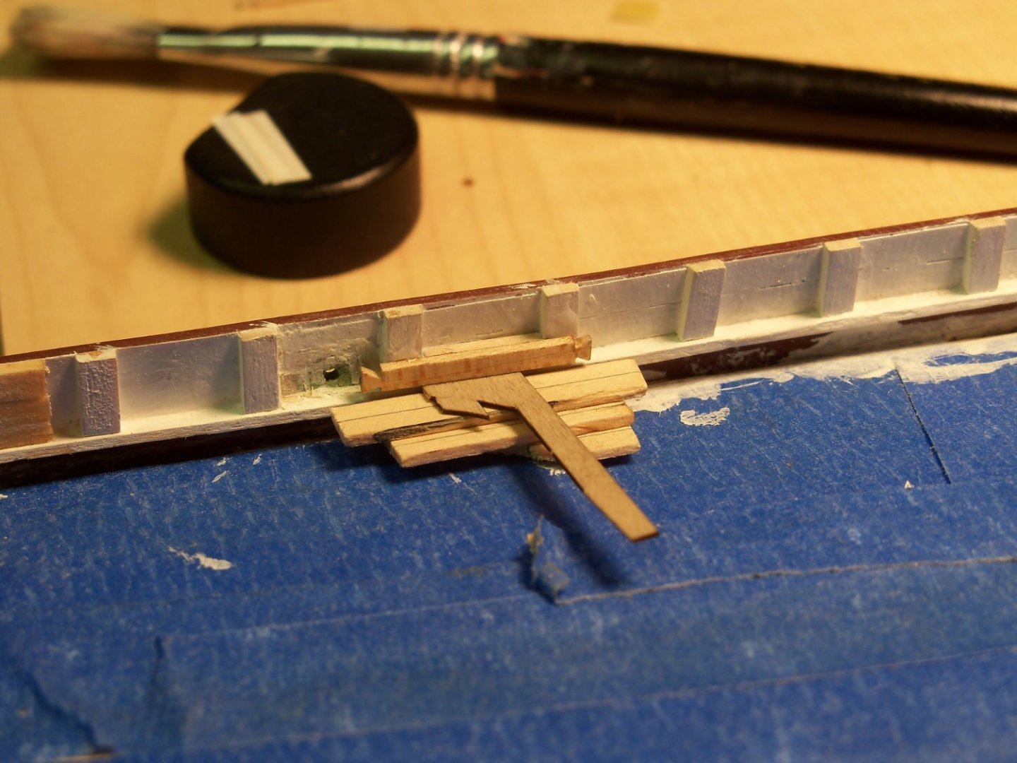
Now that the model was on a stable base, it was time to make my repair of the damaged cap rail. The damage was only about 1/8” long, but that’s what made it so difficult to fix. I had to take a file to the remaining portion of the cap rail so I could form a less ragged replacement piece and remove the finish to allow the glue to have something to grip. I used a scrap of 1/32” thick maple, a bit wider than needed, to leave me something to grip with a hemostat while machining it.
The ends were trimmed to match and a notch was filed in the joining edge to go around the deadeye strop. Once it was shaped to fit snugly into the gap, I clamped the hemostat in one arm of my triple grip third hand as shown below.

Adjusting the orientation of my patch to align with the model in the base, it was slid aside to allow me to carefully apply some carpenters glue to both the model and my patch. Sliding the third hand back into position, I carefully backed away from it
and left it to dry.
Having left it undisturbed for two days, the clamp was removed, and although it still projected beyond the edge of the cap, I found it to be securely attached. So, using some fine files and a very fine grit sanding disc in my cordless Dremel tool, the edge was trimmed back flush with the existing cap. Since my Dremel tool only required a light touch, I thought that it wouldn’t break off the patch. That’s why it did the majority of the stock removal.
Refinishing the patch and the area around it with polyurethane, I found that only close examination would reveal the repair. Who could ask for more?
I’m not sure what to tackle next, as my table saw in the very cold 🥶 garage will be out of commission now until things warm up to allow me to repair the crushed caster. I don’t want to keep taking the model off the base anymore than necessary as the grip of the mounting screws will loosen and I don’t want to install the masts and rigging until it is permanently mounted. Perhaps I will work on finishing some of the deck fittings like the fife rails since the metal ones don’t look that great to me anyway. I think that the bollards that I made look too big, and will be redone also.
-
Generally, the more bends, splitters and other fitting you add, the less suction you get.
- Canute, Don Quixote and mtaylor
-
2
-
 1
1
-
In addition to the Phantom and Wanderer listed below I also have a steel model kit of the Game of Thrones Red Keep by Metal Earth. Of course I still have the U.S.S. Constitution in dry dock waiting to be repaired. 😢
-
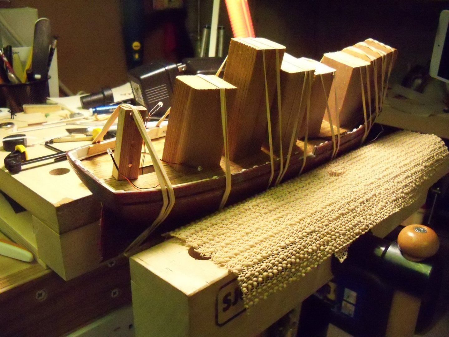
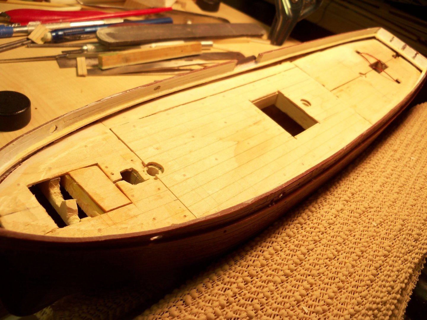
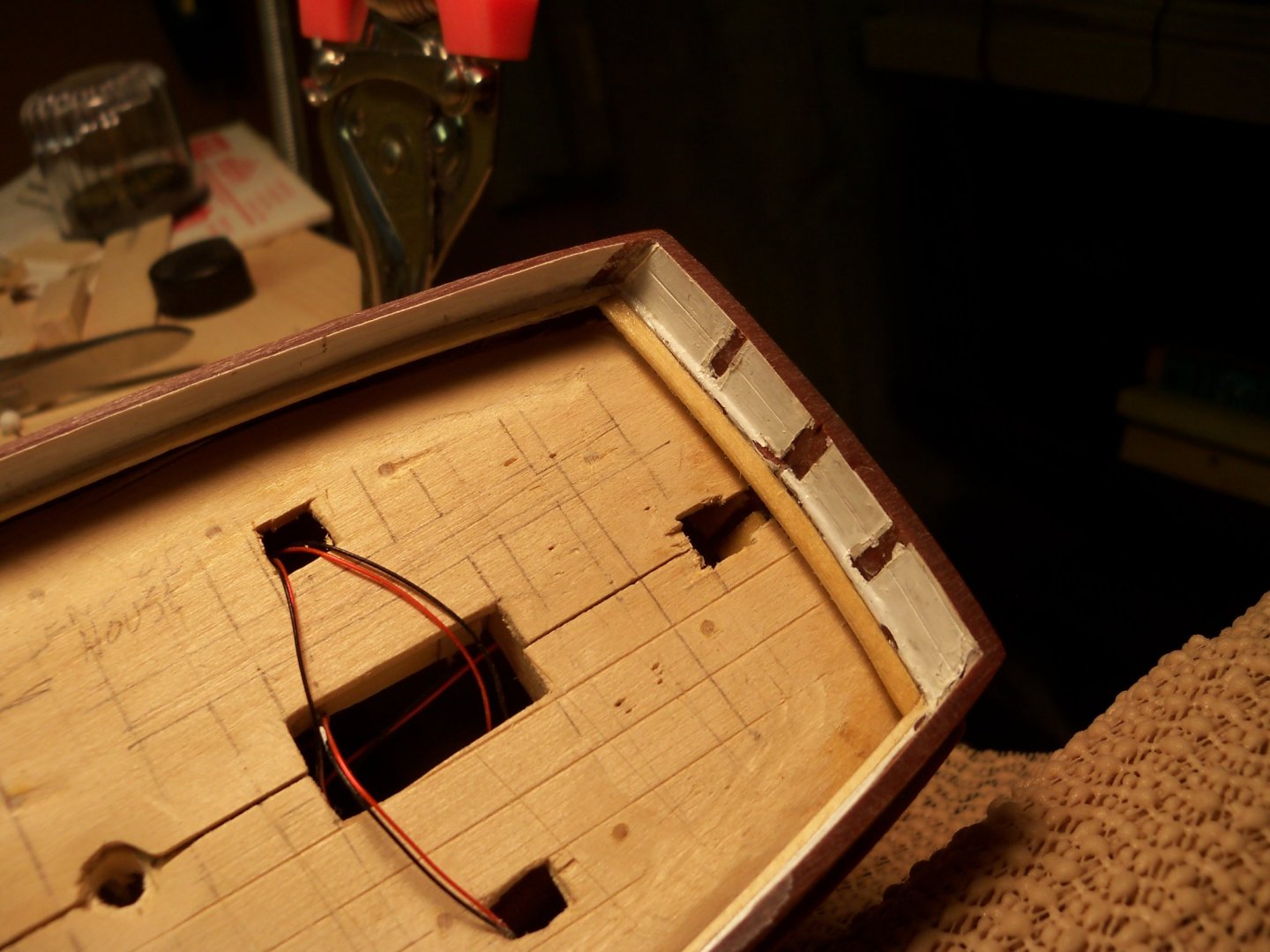
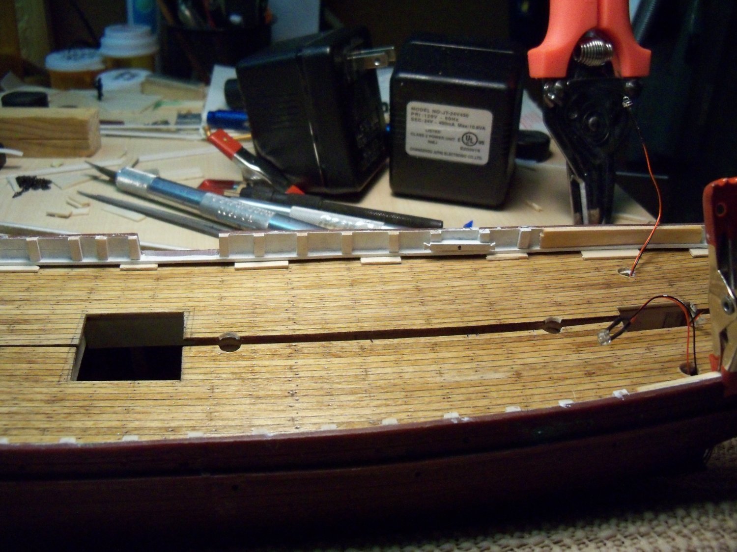
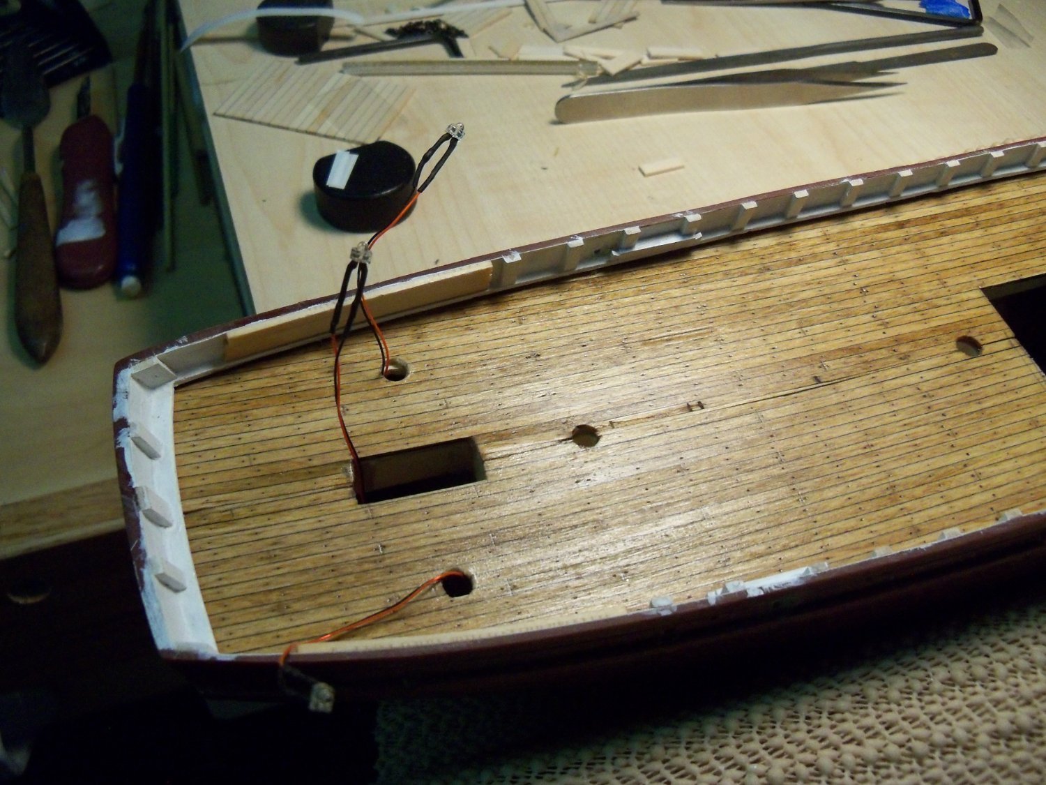
Well, it’s been a long time coming, but it’s finally time to install the two-piece finish decking panels which required quite a bit of fiddly trimming to slip under the waterways and line up at the center-line. I test fit the two panels several times, both to make sure they fit properly and to practice my clamping procedure. That’s due to the fact that the white carpenters glue that I have, only has about a five minute window before the pieces can no longer be re-positioned.
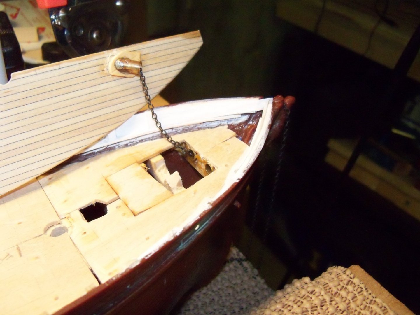
The port side was done first. Since the hawse pipe fitting for the anchor was made in two separate pieces (One through the bow and one through the deck.) the anchor chain had to be threaded through both of them before the deck could be attached. (Actually I darn near forgot about that myself!)
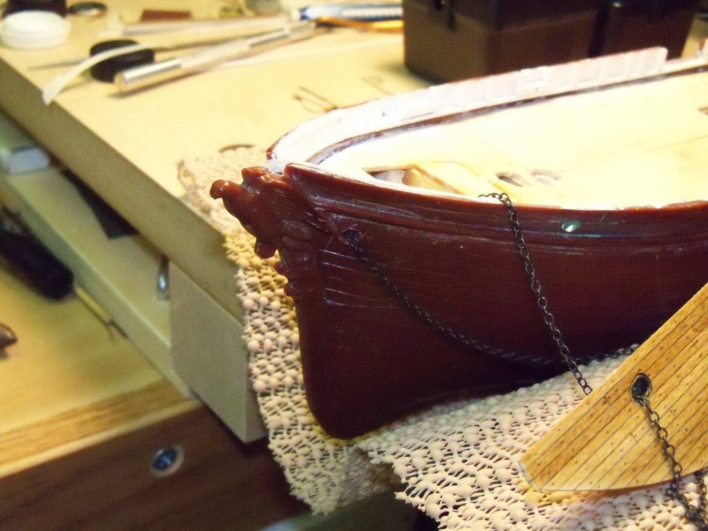
Once it was threaded through, I tied a thread to both ends to keep it from pulling itself out later when I wouldn’t be able to access the pipes. The glue was spread quite liberally on the false deck to help give me a little extra time for the glue to set. The deck panel was slipped into place, the lighting wire ends were pulled through the holes for the deck house lighting, and was especially careful not to knock off the hawse pipe fitting attached to the underside of the finish deck panel.
Several scraps of 1/32” basswood were wedged into the gap between the upper waterway and the finish deck to apply pressure around the perimeter. (As shown here on the starboard side.)

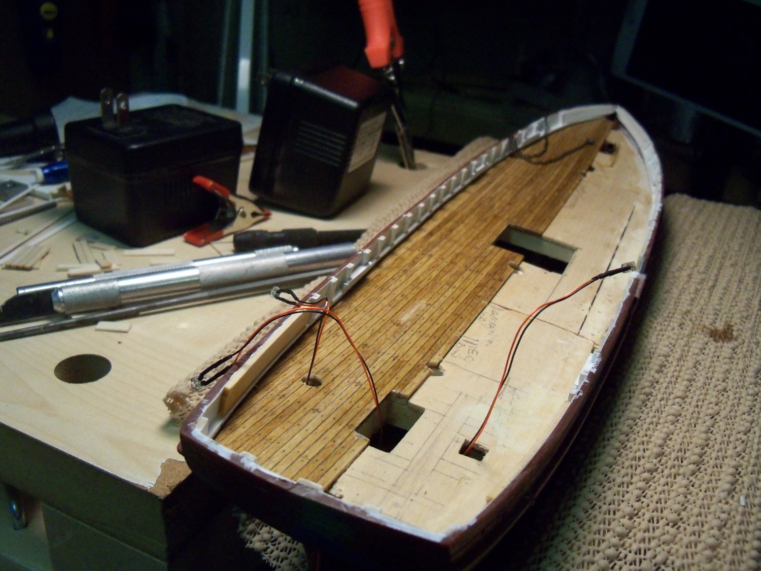
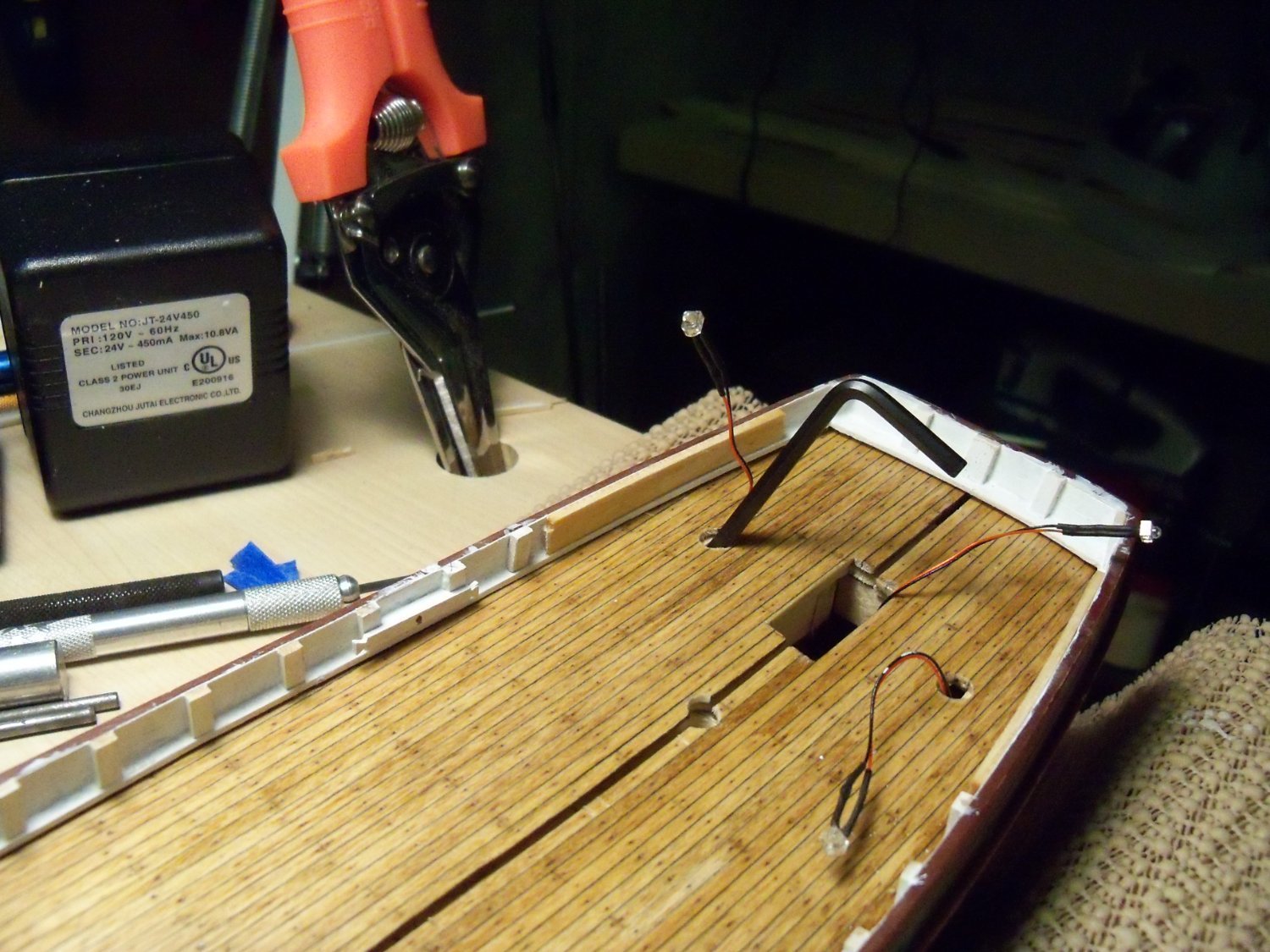
This gap will later be filled by the beveled lower waterway. After that, numerous rubber bands were stretched across the hull with short blocks of wood slipped under them to apply even pressure along the carefully positioned center of the deck as shown below.
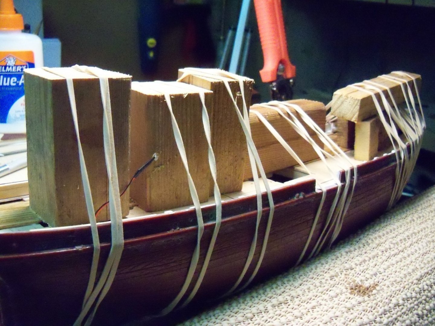
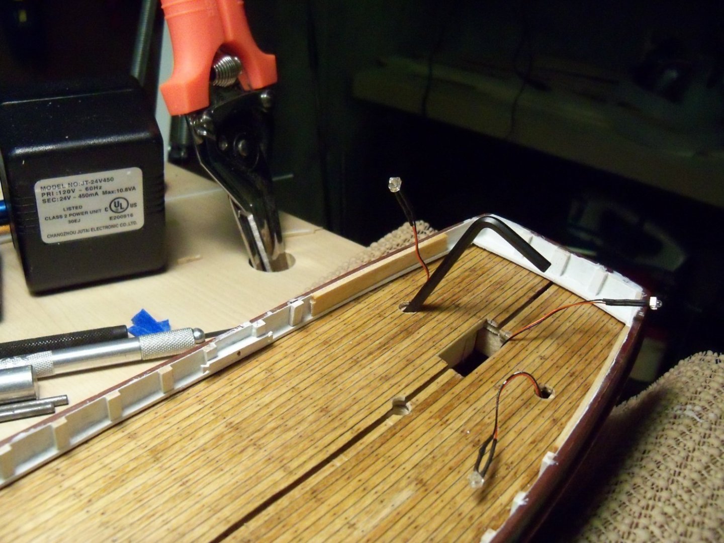
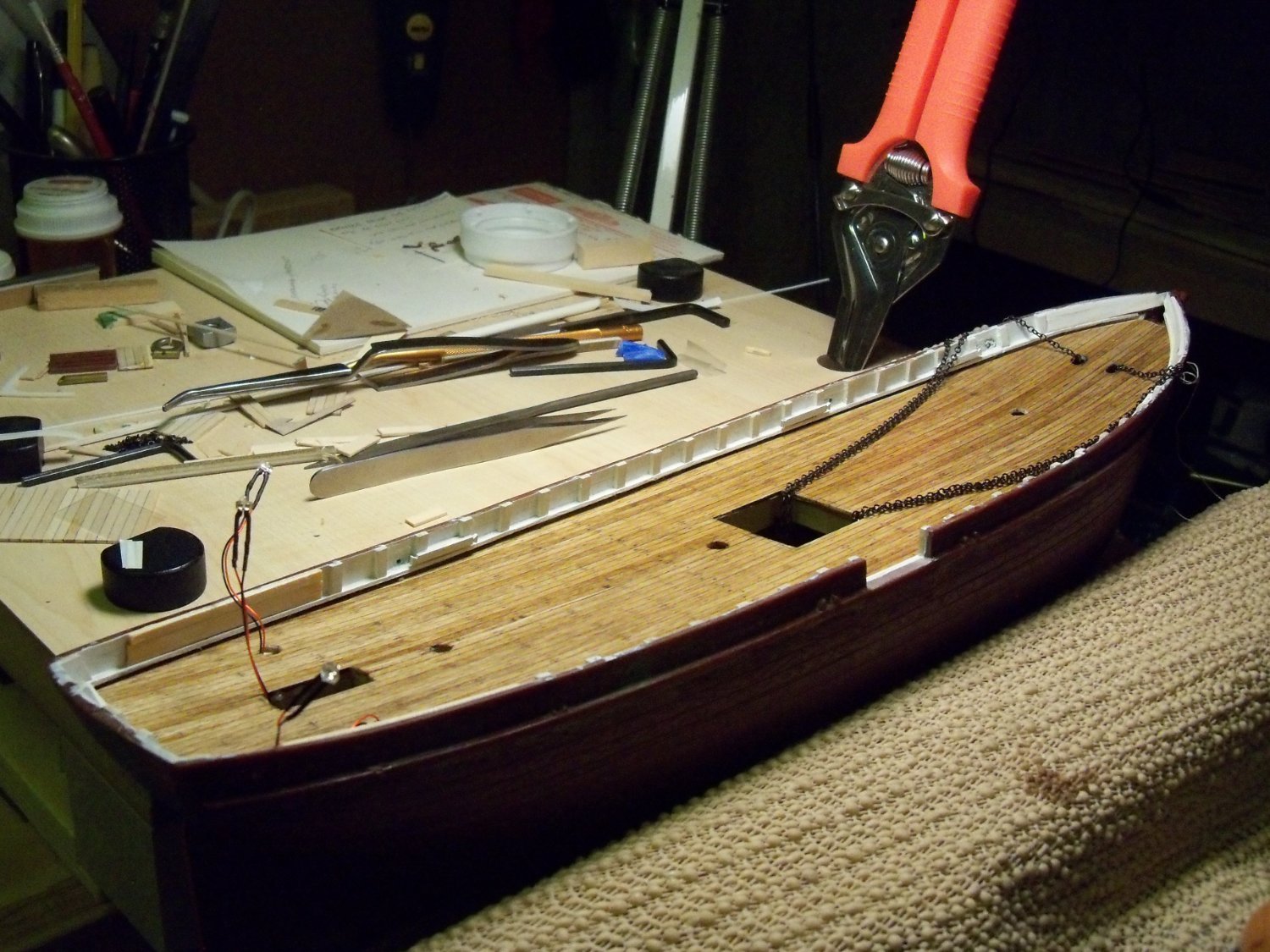
The ship was then given two days for the glue to set and I removed all the clamps and wedges to examine the results shown below.

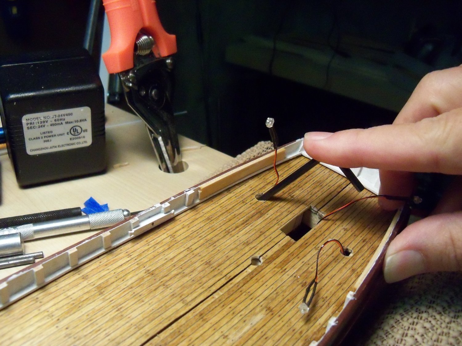
To my dismay, when testing the fit of the starboard side deck sheet I discovered that there was an uneven gap along the center line stretching from the main hatch to the stern. By inserting an Allen wrench into the wiring hole as shown below and pulling toward the center-line I found that I could close up most of the gap.

So in addition to using wedges along the perimeter, rubber bands with the wood blocks to hold down the starboard side deck along the center, I also had to apply some sideways pressure toward the center-line to close up the gap. So my hands were full, to say the least, trying to get everything done before the glue set.
After letting the glue set again for two days, all the clamps and wedges were once again removed to reveal that although most of the gap was gone, a thin tapered gap still remained! I sliced some tapered wedges from a sheet of decking and after numerous attempts of fitting, sanding, and refitting, I finally ended up with this barely noticeable filler.

Luckily, I think most of the filler will be hidden by deck structures. I think that my next feature to work on will be the beveled lower waterway once I work out how to accomplish it. Making more templates seems to be the way to go as there will have to be several gaps left for the scuppers. I think the material shall be maple rather than basswood as it will more resistant to denting when it is pushed into place. As I work out the details, I will switch over to my somewhat neglected Phantom for a bit.
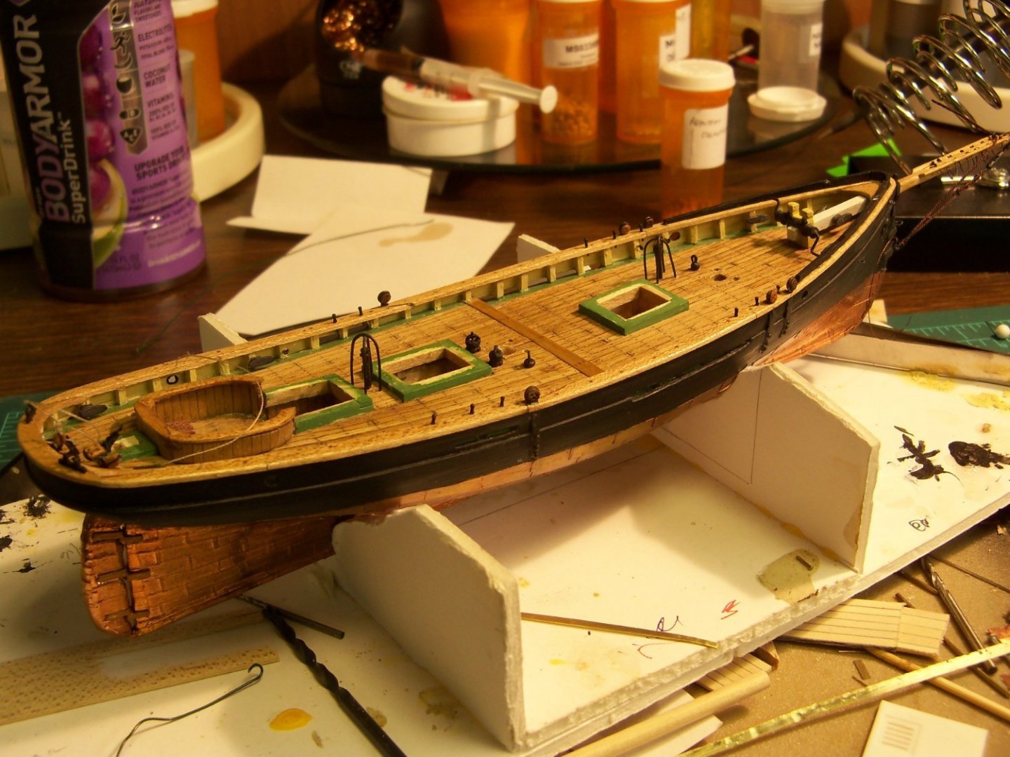
At any rate this is the current status of the Wanderer.

- ccoyle, JesseLee, Duanelaker and 1 other
-
4
-
Been away from my build (and the log) for a while now for many reasons, but I finally made a bit more progress by making the cavels.
Contrary to actual photos of the ship, both the A.J. Fisher plans and the Aurora kit indicated double timber or iron mooring bits mounted on the deck as shown below.
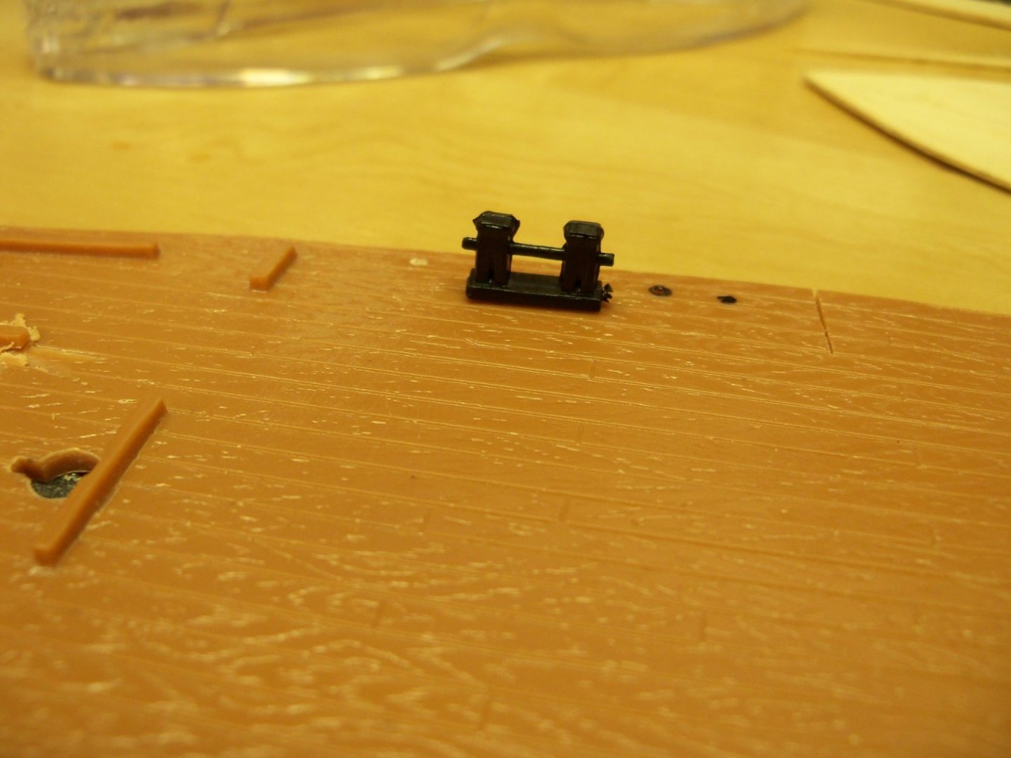

As a matter of fact, of all of the whalers of that era that I was able to examine, I couldn’t find any with this feature!
In truth, the photos actually indicated that mooring lines passed through round mooring ports and were tied off to wood cavels mounted on pairs of stanchions. Here is a detail sketch of the cavels below.
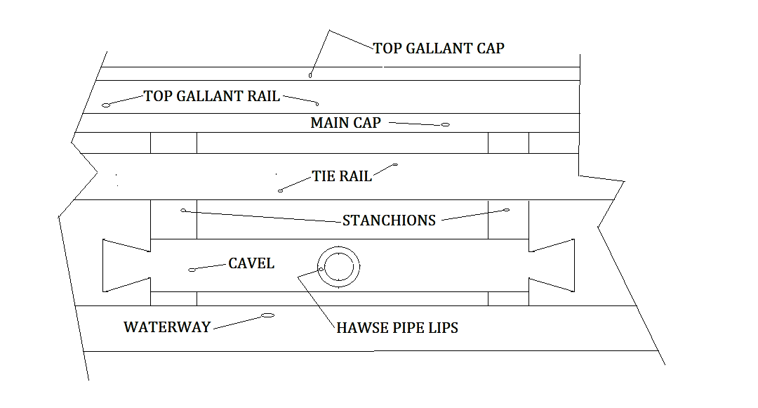
I decided to model the arrangement of the cavels similar to those on the Charles W. Morgan. Two of these mooring ports passed through the outer hull, the solid blocking between stanchions and through the cavels. The other four just passed through the outer hull and were tied off to cavels on adjoining pairs of stanchions.
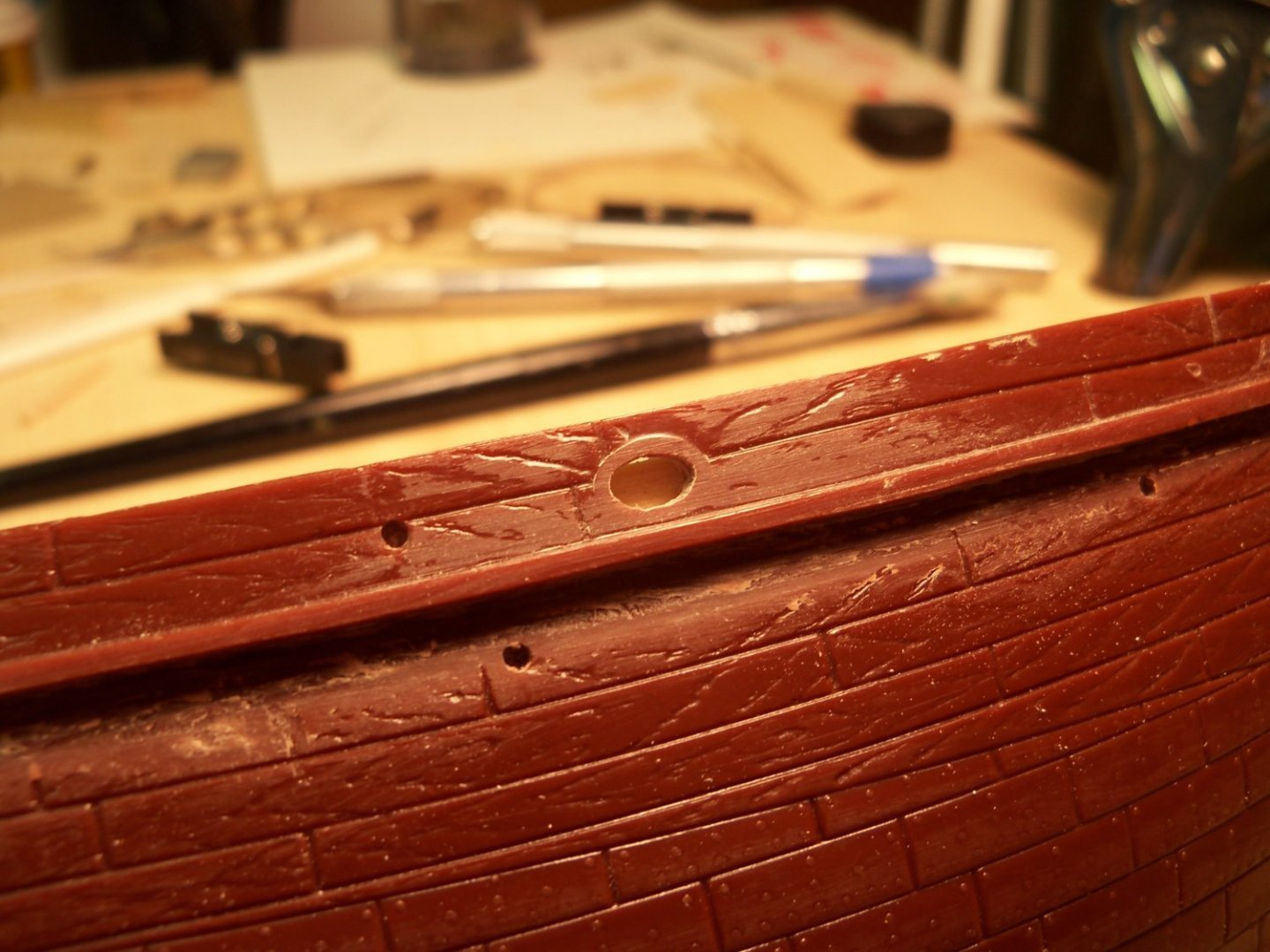
Although Aurora had all six of these mooring line ports correctly located in the plastic bulwarks, they were also grossly over sized (nearly the full height of the bulwark) as shown below. So the hawse lips on the outside surface of the hull had to be filed off flat, the holes filled in with plastic putty and sanded smooth in preparation to resizing them to match the size of the holes in the cavels and align with them.
These cavels were cut from some 1/32” thick hard maple ripped down to 5/64” wide. I nixed using basswood for these due to the fact that the two with hawse holes required drilling a hole nearly the entire width of the cavel and I envisioned problems with splitting them. (In fact, even with the hard maple, several of them did just that.)
First, I held the strip directly up against the stanchions and marked the distance from the outside edges of the paired stanchions directly onto the strip leaving a bit extra for the horns.
Second, a set of dividers was used to mark a consistent extension horn length and the cavels were cut and filed to their finished length. I found the horn ends themselves to be difficult to shape with any consistency until finally, I clamped the cavels at the bottom of my machinist vise with the end exposed just beyond the notch to line up the top and bottom of the cut vertically. Then by using a three sided mini file with one face riding flat on the edge of the vise, I filed the top edge of the cavel down until the bevel just touched the end of the horn.

Then, with the piece still clamped in the vise, I filed the bottom edge until it also just touched the end to match.
Once each end was done, it was flipped end for end in the vise and done similarly. Naturally, I cut several extras just in case any of them split. True, the angled end was a bit shorter than in the photos, but at least now the ends all matched each other.
The two cavels that needed the mooring port holes drilled through them were tackled next. Some solid basswood blocking to fit between the stanchions was cut and glued to the backside of those cavels. I marked the location of the holes in the center and brushed the face of the pieces with poly and let them dry before actually drilling the holes to help prevent them from splitting, since the holes were nearly the same width as the cavels. Drilling a small pilot hole with a pin vise, I gradually increased the hole to the inside diameter of the hawse pipe lips.
Once all of the cavels were all completed, I made this jig below from scraps to hold them in position 1/64” above the upper waterway while gluing them into place.
Making those tiny mooring pipe lips maybe beyond my skill, but later on, after applying the self-adhesive backed wood-grain tape on the outer hull, I will attempt to see if I can form some new lips for the inside and outside lips. For now, I’ll simply leave the holes.
Right now I needed to find a way to align those holes in the cavels with the holes passing through the blocking and the plastic hull, because I didn’t have enough room to get a regular drill in place between the bulwarks. This was eventually solved by using a much smaller drill bit mounted in this micro drill chuck that can handle up to a #61 bit and closes to 0. It’s perfect for getting into those tight spots.
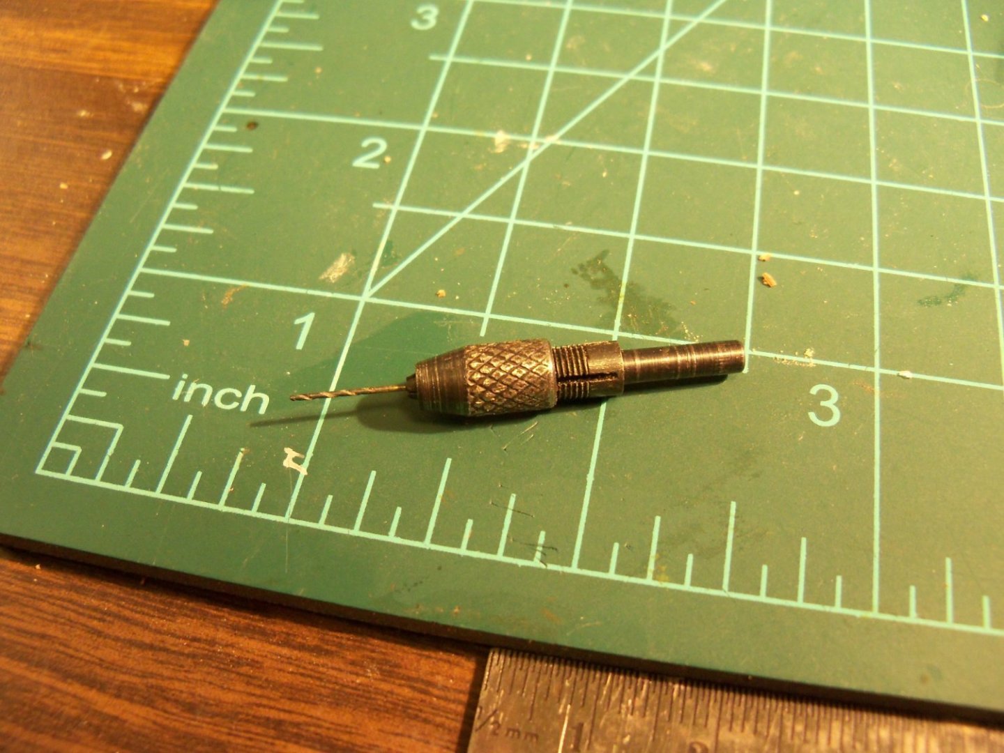 I simply laid the drill bit flat with the bottom of the hole in the cavel and drilled it by hand until the bit emerged on the outside of the hull. This gave me the position of the lower edge of the hole on the outside and by allowing for the size of the new bit, I was able to enlarge the hole to align with the hole in the cavel.
Now that the cavels are installed, the insides of the bulwarks were given the final coat of white paint and all of the masking was removed.
-
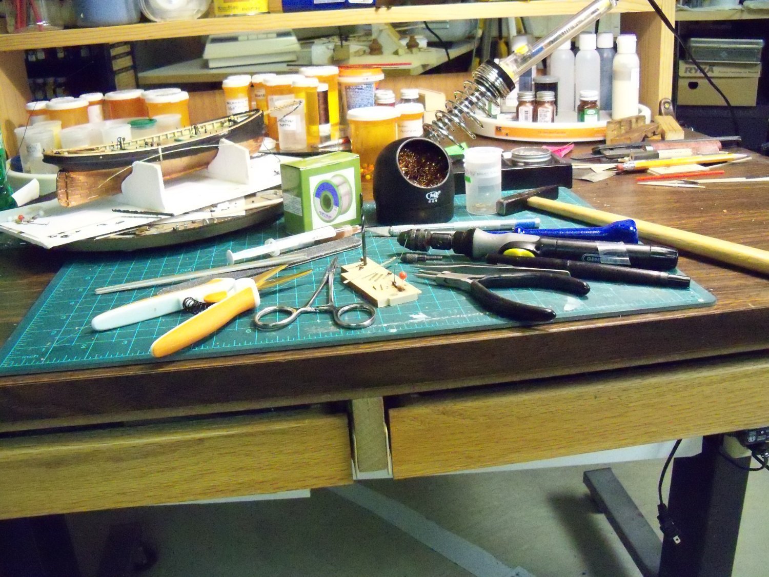
Taking a break from my Wanderer build, I shifted my focus to fabricate and install the lower portion of the deadeyes for the Phantom. Rather than using Chucks method of tying the deadeyes on with thread, I decided to try my hand at soldering again. Here is a photo of all the tools needed to complete these tiny fittings.

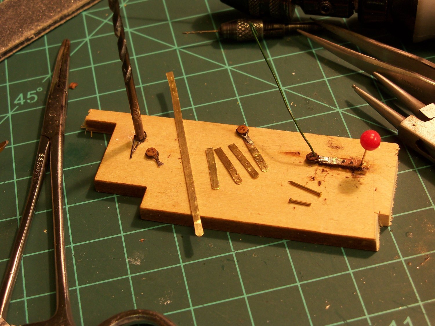
This close up shows the process in order from left to right.
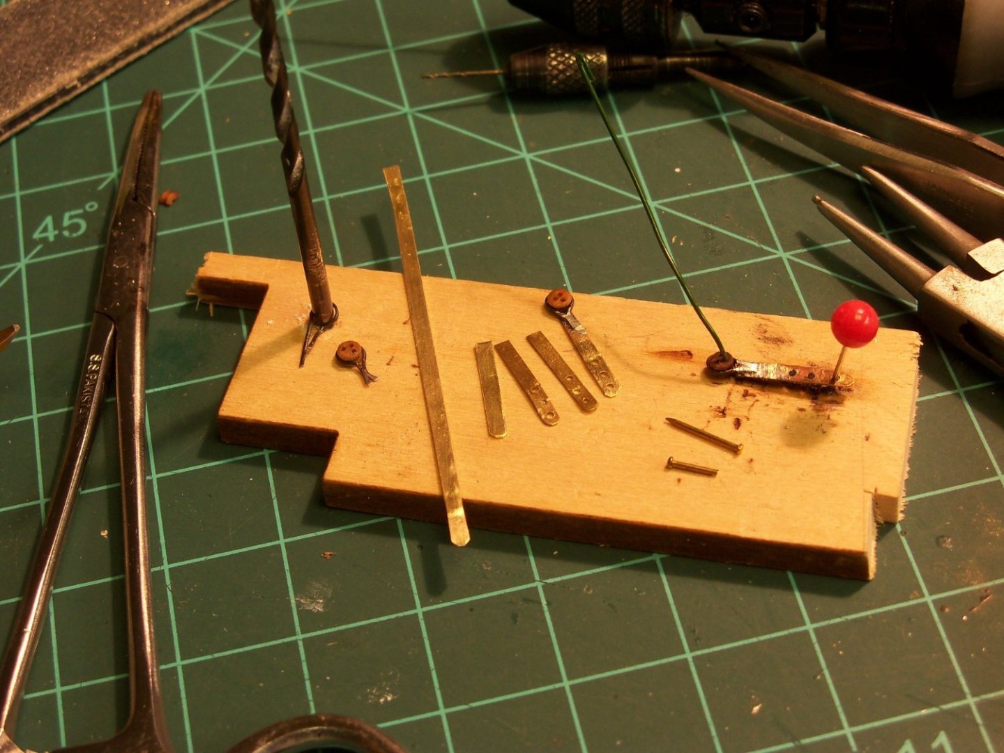
The first step was to make the deadeye strops by wrapping some .27mm blackened brass wire around a 3/32” dia. drill bit, leaving the tail ends slightly extended from the bit. These ends were trimmed off even and flattened with a hammer. A deadeye was inserted into the opening and pinched closed as shown leaving a thin flattened tail that was smoothed with a file to solder to the chain plate.
The next step was to make the chain plates. I took a sheet of .026 mm brass to the bench and clamped it down with a metal ruler and proceeded to repeatedly score a 2.0 mm wide strip with an old #11 Exacto blade with the tip broken off until I could snap the strip off. The strip was cut into eight 13.5 mm lengths and the corners were trimmed off one end with a metal snips. (That’s 6 to use, and 2 extra just in case.)
When that was completed a sharp metal awl was used to mark (one at a time) the locations of three .69mm holes on the trimmed end. I flattened the plate and drilled each hole before going to the next one. Once all three holes were done the plate was flattened once again and sanded smooth.
Now that the three main components were done, they were pinned in place on this jig and soldered together. My procedure for soldering is still a work in progress, but after several failed attempts I managed to work it out by first putting a dab of solder paste between the face of the chain plate and the back of the strop. Then another dab of paste was placed on the face of the strop that allowed me to stick a tiny bit of solder on top of the assembly.
When the tip of the hot iron was held against the chain plate, the solder behaved as hoped by melting and flowing were it belonged to make a nice shinny joint. The excess solder was filed down flat so they could fit into those tiny slots that were now drilled and filed into the cap rail for the chain plates as shown below.
The masts were temporarily set in the deck with a length of chord clipped to the masts where the backstays will be anchored. That chord allowed me to align the chain plates with the backstays as shown below.
Once the angle of the chain plate was established and marked on the hull, the plate was held in place to mark the location of the bottom hole in the plate. I used a .69mm drill to make the hole and tapped a full sized pin through the hole into the hull. The plate was secured with the full size pin in the bottom hole, the other two holes were drilled directly through the plate and half sized pins with a tiny dab of CA on the end were tapped in place.
Now that all of the chain plates were installed, they were given two coats of Model Shipways MS4828 iron/cannon black paint. Some touch up painting is still needed, but the next phase of the project will be to mount it on a finish base to reduce the chance of damaging what I have already accomplished.
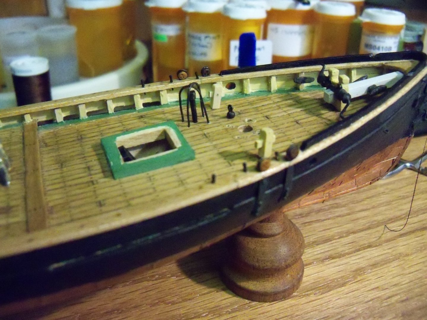
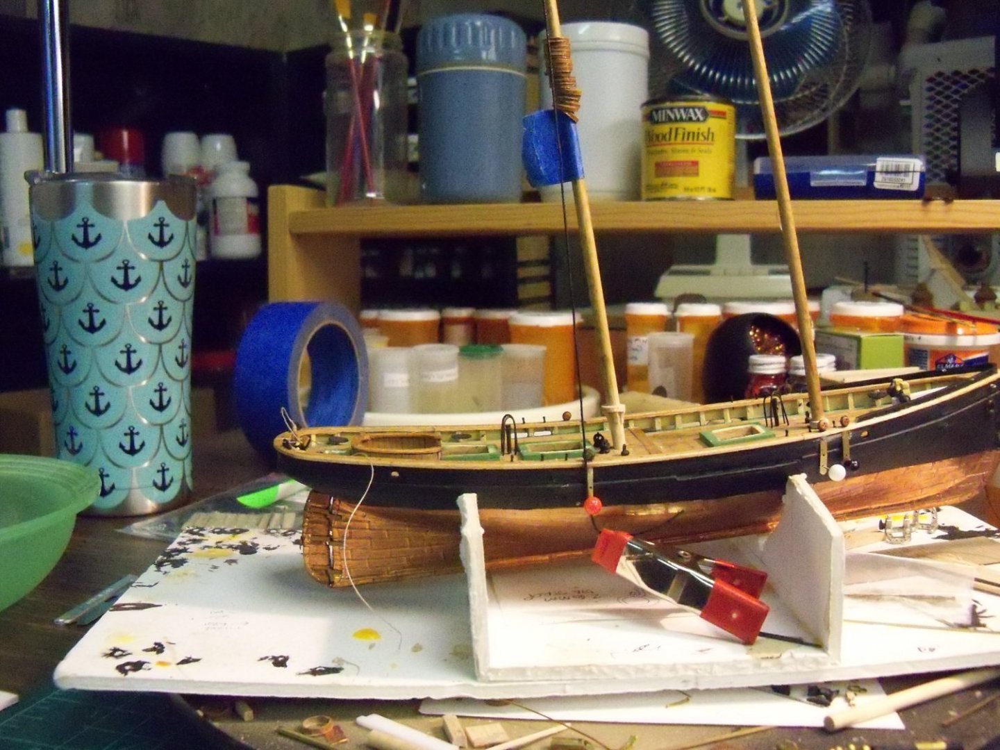
Here is the ship as it stands now.
------------------------------------------------------------------------------------------------------------------------------
-
Welcome aboard Mike. We are always happy to share our hobby with others. Your skill level doesn’t matter as we cover every level here from the novice to the artisan. Get familiar with using the forum and start a log on your first ship so if you do come across any problems with it the rest of us can give suggestions to help solve them. Don’t get discouraged if you don’t feel that you measure up to the results that some of us show, as we all had to start somewhere and it’s all about the journey to keep improving our work.
-
On this photo the grain doesn't seem to be all that critical since these all just seem to have the grain running vertically.

As far as mass production goes, they can just be shaped with overly thick legs and the angle could be easily modified with a belt or disc sander for the ones that didn't match. If you look at posting #39 and #41 in my Wanderer build log, you can see how mine were made. In my build the angle was 90 degrees, but as I said they could have been just as easily modified with the sander.
- Canute, Roger Pellett, Chuck Seiler and 1 other
-
4
-
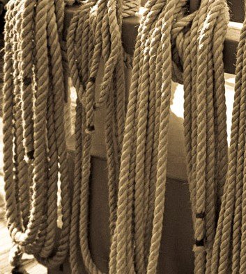
Is this the method commonly used to prevent lines from unravelling throughout history or is this more of a recent method?
-
My "antique" Craftsman 8 inch table saw (1936 vintage) with its cast iron top is still my go to tool for ripping planks. I use a narrow kerf ripping blade, which while it still takes a rather wide chunk of wood, it has the HP to slice through the toughest woods like butter. The key for me is the set up, I can consistently peal off planks down to 1/64" thick once it is set up properly.
-
My strategy for gluing down the finish decking is to use 1/32” thick scraps of basswood (the beveled waterway thickness) as wedges to hold down the edge of the decking while clamping down the center of the decks with blocks of wood on the deck and rubber bands around the entire hull. Since this will be a somewhat time consuming procedure I will be switching to some Elmer’s white glue that requires a longer cure time.
This requires the top edge of the false deck to have a gap of 1/16” below the waterway extension. (That’s 1/32” for the finish decking plus 1/32” for the beveled waterway.) With a very sharp chisel I went all the way around the hull and carved the gap close to that required, and finished up with a sanding disc mounted in my Dremel tool.
Once that was finished, I drilled those elongated holes in the finish deck for the anchor chain hawse pipe fittings and shimmed the fittings with 1/32” thick basswood so the top of the fitting was flush with the deck surface. These were then secured with some thin CA. Access holes for the LEDs in the deck houses were drilled and the opening for the skylight was cut.

Once the waterway extensions were installed, I used a pallet knife to fill the gap in the extension with some Elmer’s wood filler.
The stanchions, made with 1/16” x 1/8” basswood, were tackled after the waterways were sanded smooth. The basswood tends to finish rather fuzzy, so whenever I use these thin strips to make tiny repetitive parts, the first thing that I do is to lightly draw the whole strip between my fingers and a fine grit sanding stick. Flipping the strip over to do all four faces this way doesn’t reduce the dimensions of the strip by much at all, it just takes off the fuzz and leaves me with a nice long handle to draw the strip.
Once the strip is smooth, one end of the strip is cut square, and it’s stood up vertically in place. If any adjustment to the cut is required, like a back bevel or angle side to side, it’s adjusted with a medium grit sanding stick while using the excess as a handle. For these stanchions, I set up my Chop-It block with a sharp razor blade and set the stop just a bit overlong to the height of the bulwark, leaving the remaining to be sanded flush after placement. (Since the top of these stanchions must meet the bottom of the main cap so it can lie flat with no visible gap).

I determined that the center-to-center spacing of the stanchions was about four feet to scale. Taking my original paper deck template and a compass set at this spacing, the locations were stepped off along the edges and marked. The template was set in the waterway gap on one side and a stanchion was held in place above each mark and given a drop of CA glue to secure it. This was repeated for the other side and finally the five stanchions at the stern transom were glued in place in the gaps left where the previous ones were removed.
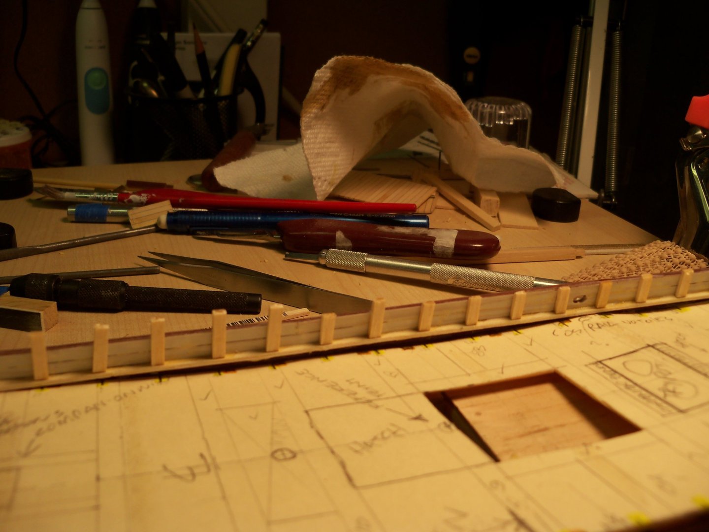
On this ship there were a total of 44 stanchions visible, but this whole process only took about an hour to complete. After the glue set overnight, the stanchion tops were all trimmed off. Then after a bit of masking, my newly made - and as yet untested- spray booth will finally be utilized to spray the inside of the bulwarks white! Here are the trimmed stanchions in place.
- Cathead, GrandpaPhil, yvesvidal and 2 others
-
5
-
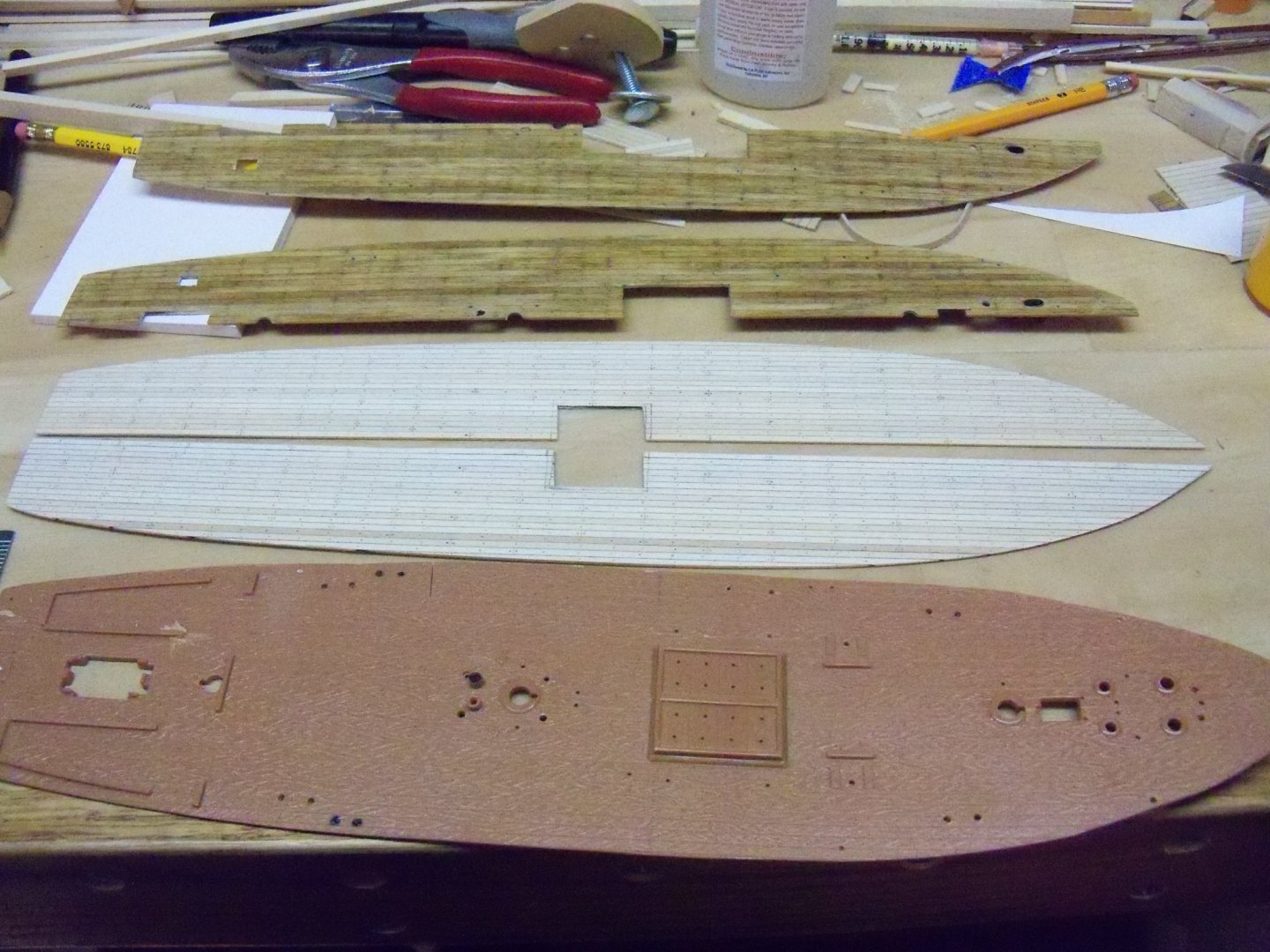
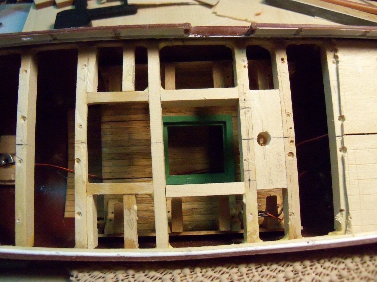
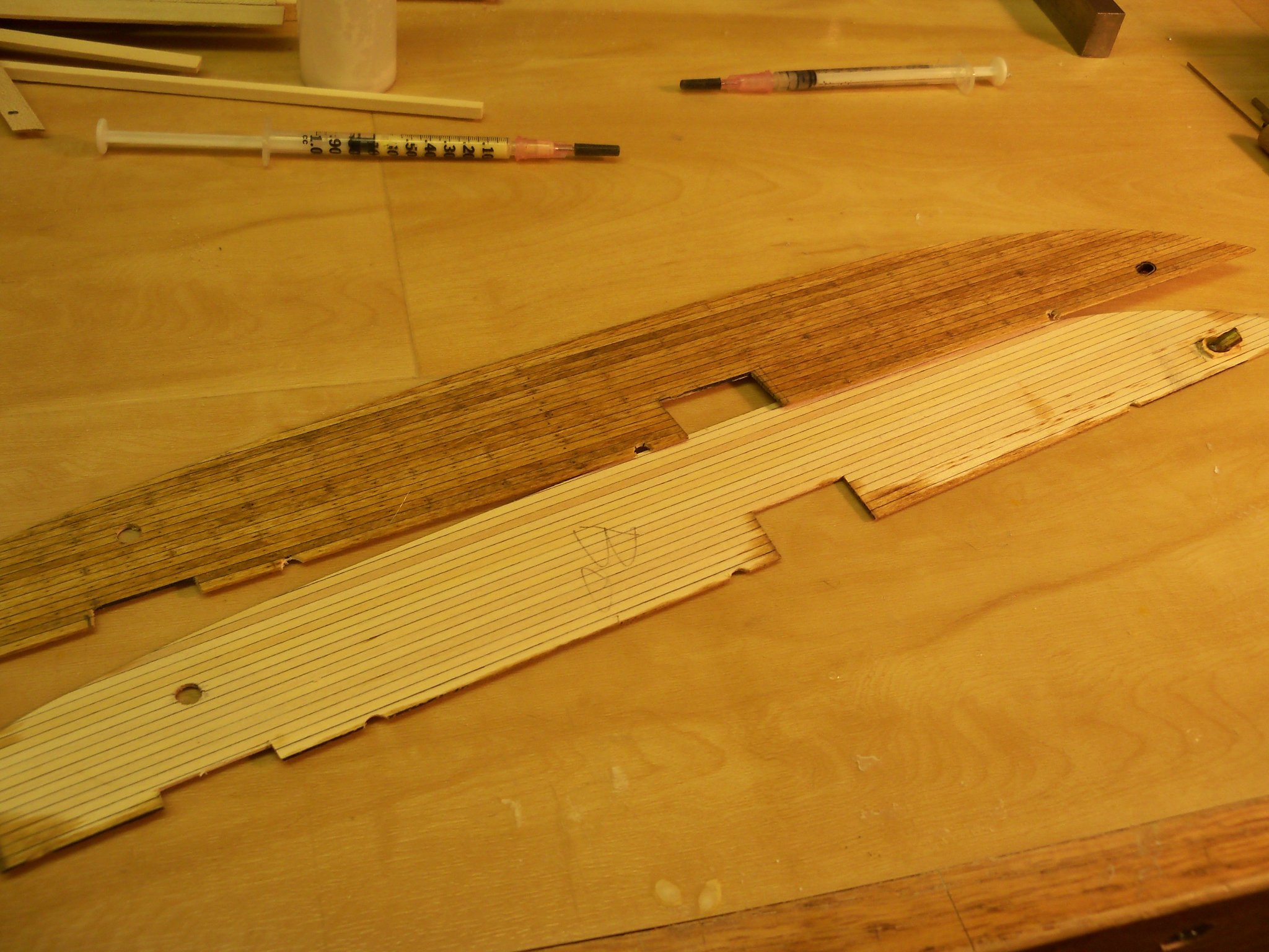
At first I thought about simply cutting the new hatch opening in the existing finish deck and patching the old hole, but unless the patch could replace the center of the deck from the trypots structure all the way back to the deck houses, the patch would be obvious. Unfortunately, I didn’t have enough of the 1/32” deck planking with 1/8” wide deck boards remaining to do that.
I did however, have two sheets of the 1/32” basswood decking with 3/32” wide planks, So I decided to use them. While these planks are narrower than the ones on the lower deck, I don’t think that it will be all that noticeable. The trennel pattern needs to be slightly different, as each plank will show only one at each beam as opposed to the wider planking that had two, but the plank butt pattern will be the same.
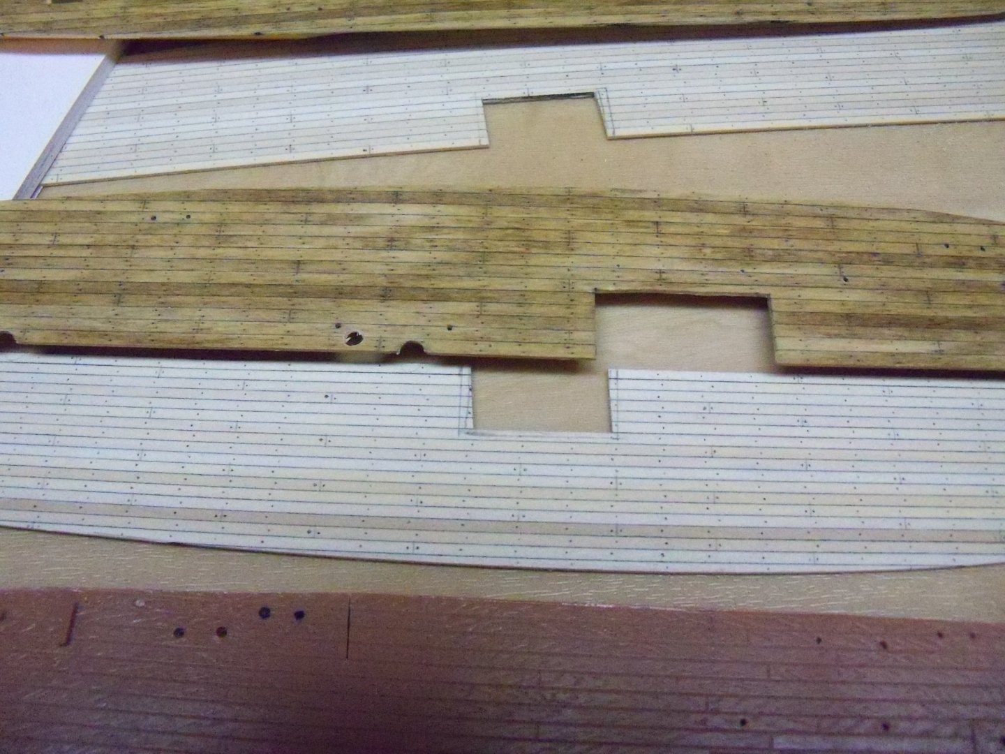
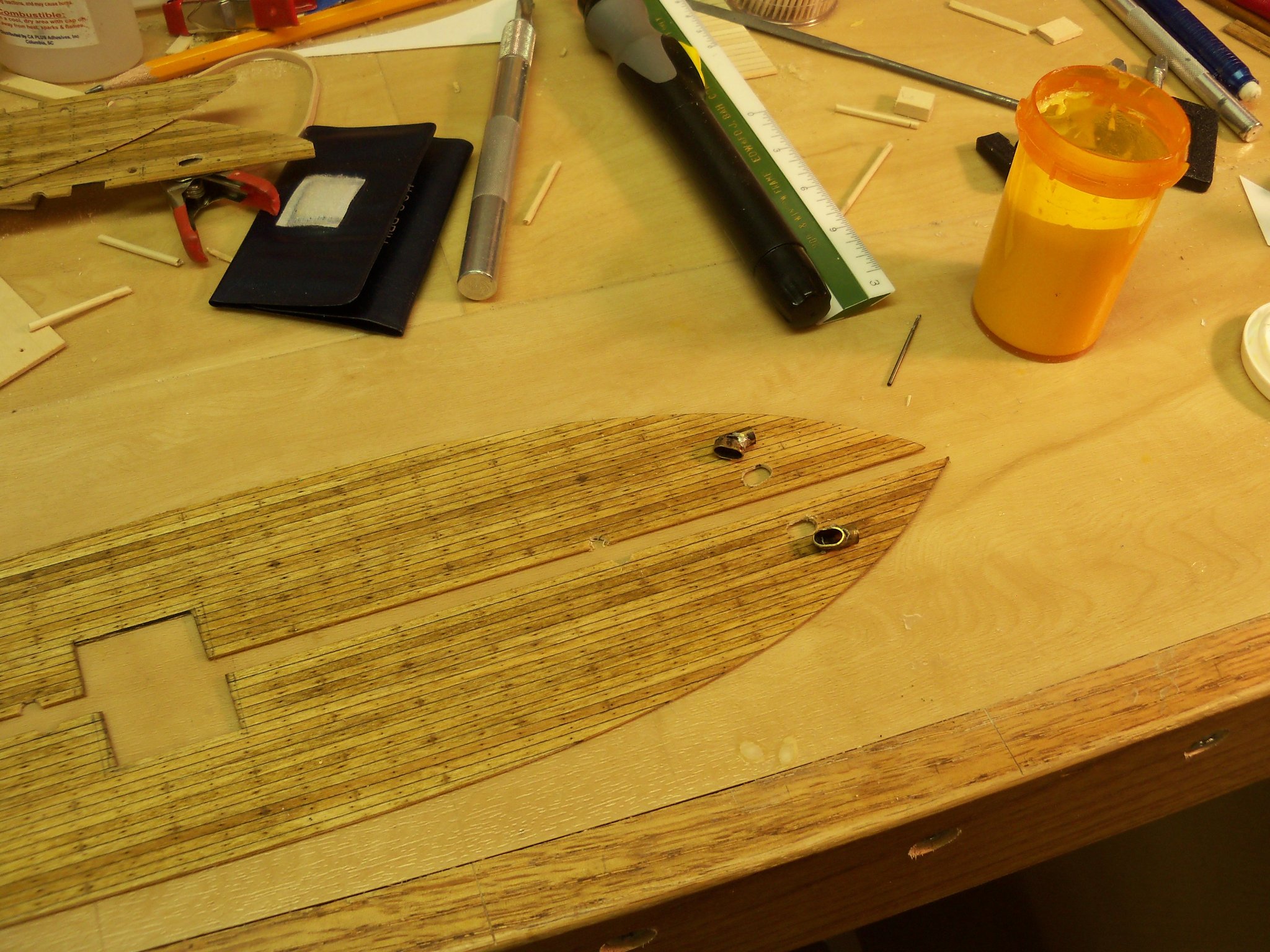
Taking the old finish decks and taping them onto the new sheets, the shape was traced onto the new sheets. The new sheets were roughly cut with the scroll saw and finish shaped with my small belt sander as done before, but with the new hatch location cut out. Next, the new decks were taken back to the drawing board and the butt and trennel pattern was applied. Here is a photo comparison of the original plastic deck and the two wooden ones, showing just how far off the hatch location was.
Here is a closer view of the plank trennel pattern of the wood decks.
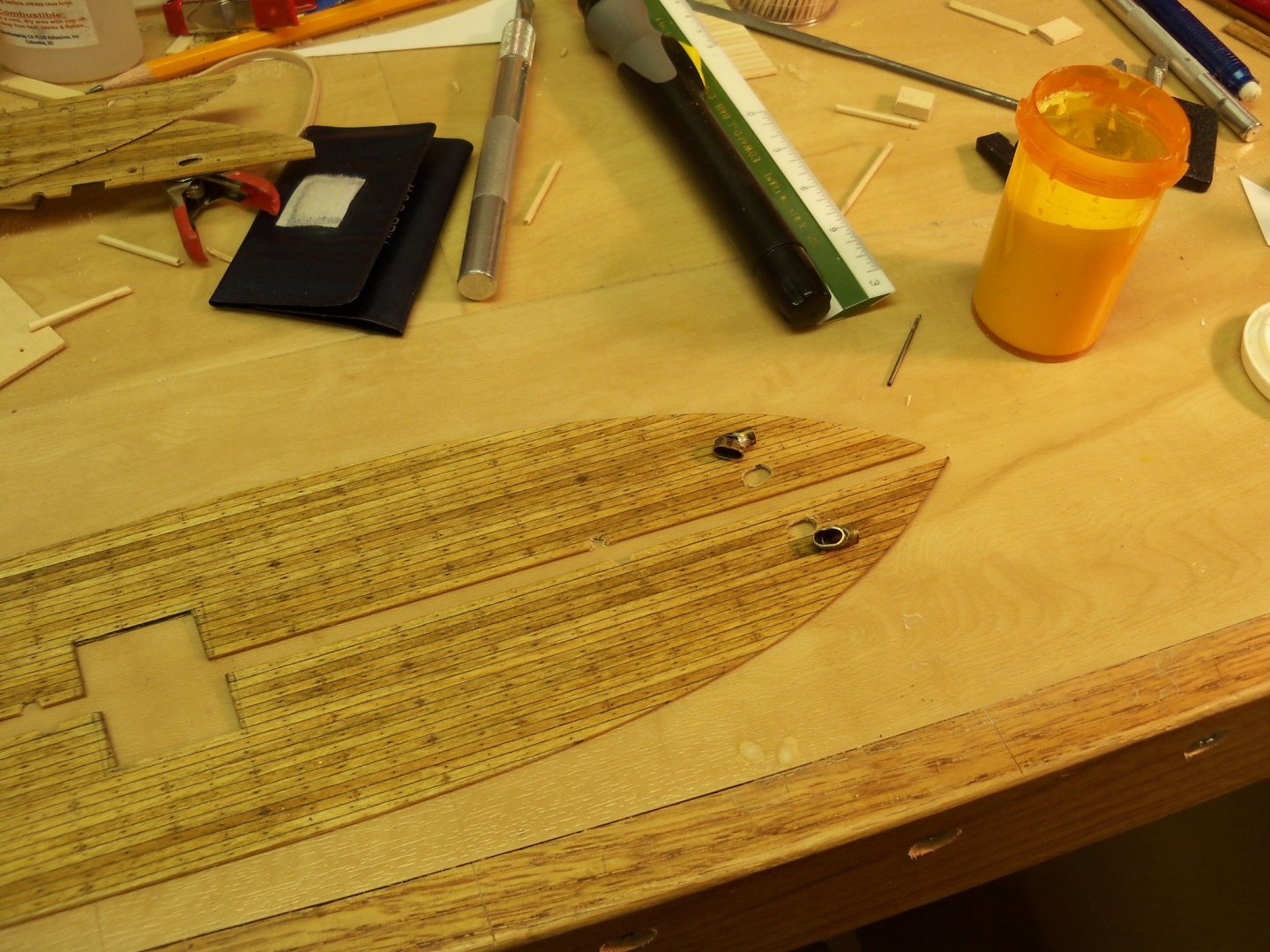
The silver lining in the extra work involved was that patching of the incorrect anchor chain openings in the deck, the holes for the bollards (which were never a feature of the ship), and the other erroneous holes would no longer be needed to be patched.
The new finish decks were stained with Minwax light oak finish to match the old decks, given two coats of polyurethane and set aside to dry.
Meanwhile two new sections of the false deck were cut and fit to replace the old sections that were no longer usable. They were drilled and new trennels were used once again to glue them down.

Having set overnight, the stubs of the trennels were snipped off and the bulwark foil tape finish was removed in the areas where the new stanchions would be visible, since both their size and spacing were wrong. (If anyone has any doubts about the effectiveness of the adhesive on the tape, rest assured that if the difficulty of removing them is any indication, they will stay put for a long time!)
I also felt that a little reinforcement for the decking at the chain hawse holes was needed, so I glued a hefty timber below the decking for that. Then the trennel ends were all sanded flush to the deck.

The anchor chain hawse pipe fittings were carefully removed from the old decking so I can use those holes drilled in the decking as guides for drilling matching holes in the new decks.
Taking strips of 3/64” square basswood, the waterway extension was added by shimming it in place and spot gluing it with CA glue. Once they were held in place the shims were removed and I ran a continuous bead of CA on the entire run of the extension. (Since the waterway will be painted white rather than stained, the CA discoloring of the extension was not a concern and the glue will allow the extension to become hardened.)

Applying the extension across the stern was the most difficult area to apply. The angled stanchions were removed, but since the new ones will occupy the same spots, the tape was left as is. I wasn’t happy with this first attempt with bending a single 3/64” stick, as it wasn’t wide enough to cover the edge of the deck when it was test fit.
At first, an additional stick was added, but the joint was too obvious. These were removed and replaced with this 3/64” x 1/8” strip scribed to fit as a 3/16” wide waterway.
Lastly, I replaced the white foil tape on the areas of the bulwarks that I had just removed in preparation to installing the new stanchions.
-
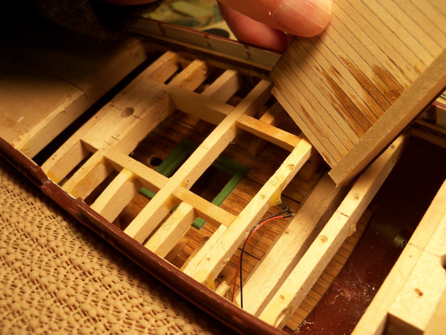
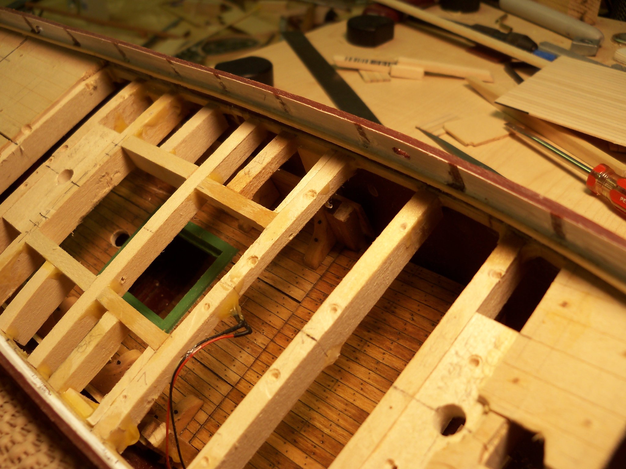
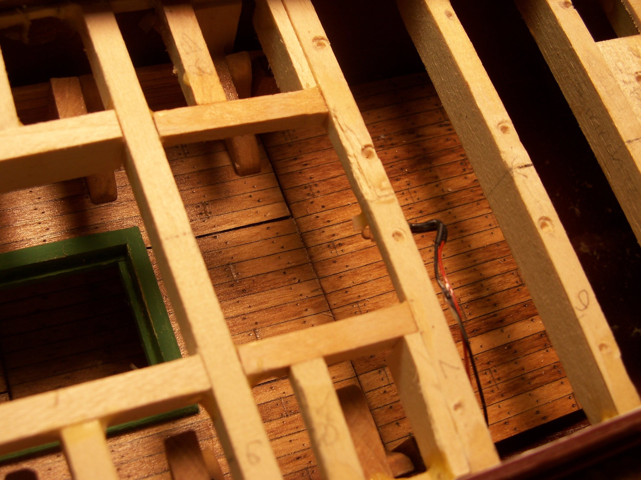
Now that the lower deck was secured, the fact remained that a bit more of that deck would now be visible through the new upper hatch. Checking the sight lines through the new hatch opening, revealed that there was a fair amount showing, but the deck toward the main mast looked to have better access, so I decided to tackle that end first.
I cut a 3/16” square piece of basswood for a tight fit between the sides of the hull, butting one edge up against the side of the suspended decks’ support beam to form a support ledger for the deck extension. Leaving the top edge 1/32” below the top of the decking, I glued and wedged it into place.
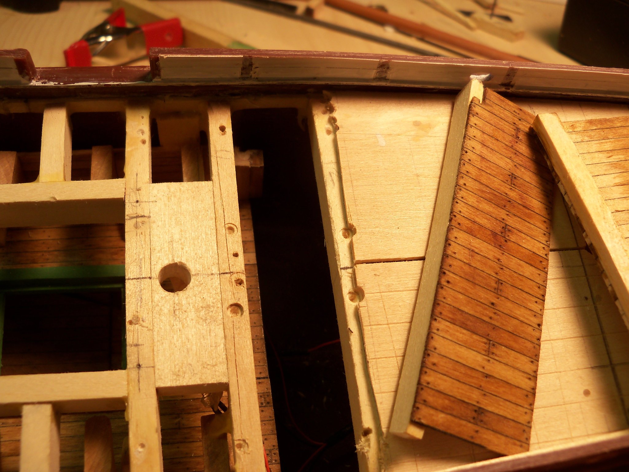
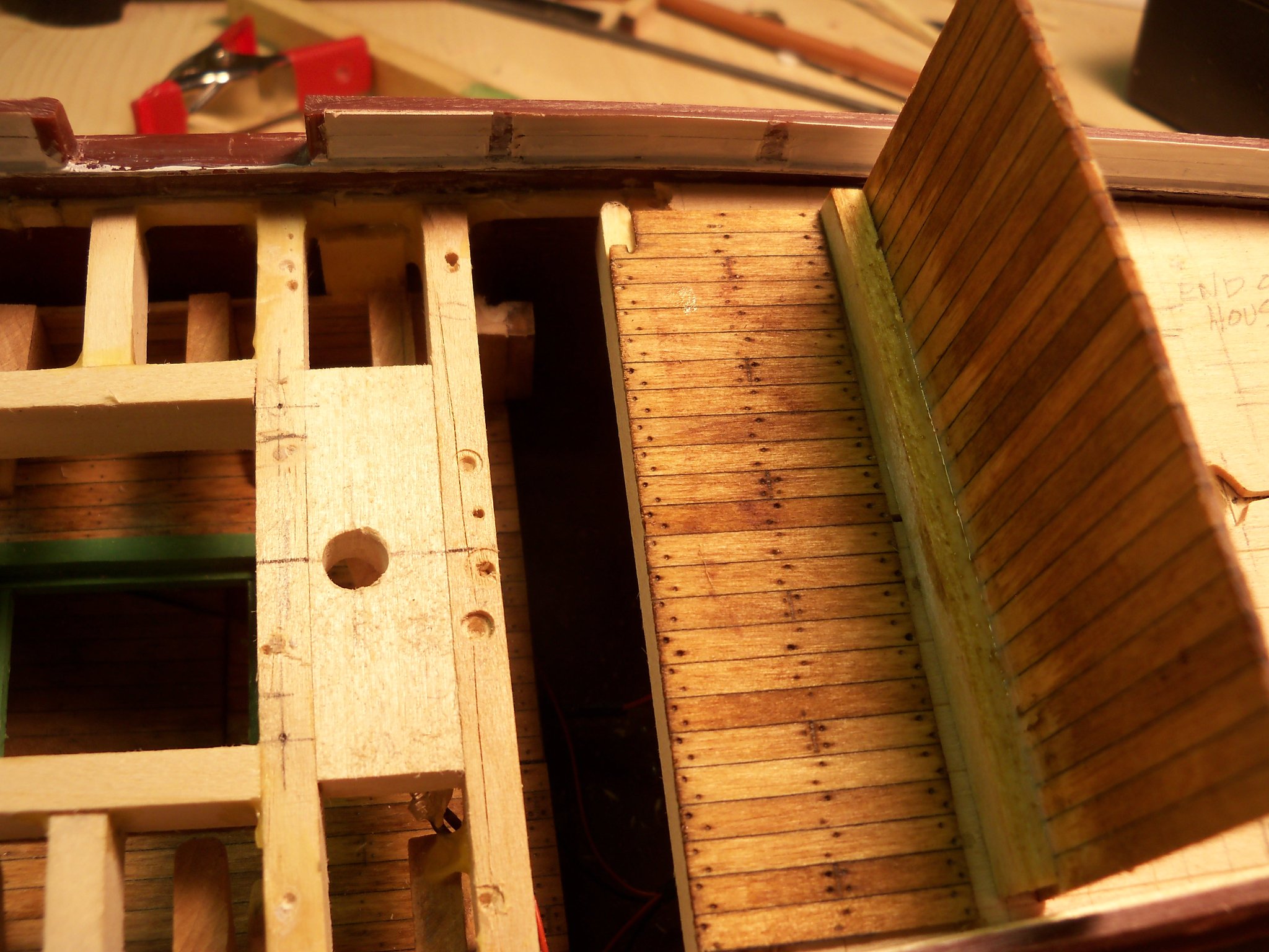
This left me a support ledger for the rear end of the new deck. I took a left over section of decking and cut notches to fit around the corner posts of the lower deck. The length of the decking was determined by the sight line towards the foremast, and I cut it off just beyond that line which turned out to be a scale 15 feet. I duplicated the trennel and plank butt pattern of the lower decking and finished the deck to match as shown here.

Using another basswood timber, a support beam was cut and glued on the bottom side of the decking with thin CA glue for the forward edge of the deck.
Since the inside of the hull narrowed down here somewhat, the assembly was trimmed and test fit several times until its deck was level and flush with the suspended deck. Once I was satisfied, carpenters glue was applied to the top of the support ledger and the decking was pressed in place. Using the bamboo stick once again, the carpenters glue was poked down between the beams and used to set the front edge of the deck. As I couldn’t use a clamp to hold the assembly in place, I just took a short scrap of wood the width of the space between the upper and lower decks, set it on the decking extension and placed a weight on it until the glue set. Here are some views of this lower deck extension in place.

The deck extension toward the main mast needed to be nearly as long as it was at the foremast, but the wiring was in the way and the access was more limited, so this section was handled a little bit differently. I made up another deck extension similar to the previous one, but at a scale of only 6 feet long. A ledger beam was made up for the front end of the extension and glued also with thin CA to the end of the decking as shown here.
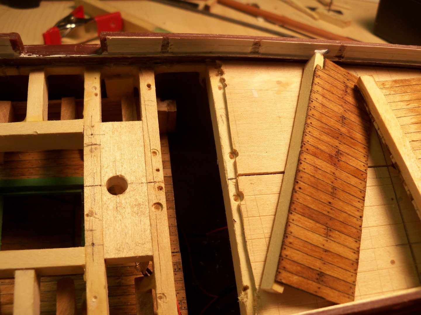
Now in order to provide support for this extension, I decided to make somewhat of a partition wall that I could attach to the face of the main deck beam #12 above. Taking a 2 inch long section of decking, a length of 3/16” square basswood was cut to match the width of the extension. With thin CA glue it was attached to the bottom end of it forming the wall itself. This was stained to match the deck and is shown below standing backwards on top of the extension.

The partition wall was turned around to hide the base beam and glued with thin CA to the top of the extension decking, leaving just enough decking exposed to allow the wall to be vertical when butted up to the face of beam #12 above. The wall was purposely cut 2 inches wide to leave a handle to hang onto the assembly and tilt it down into the opening in the beams above. The ledger was given a generous coating of carpenters glue and the assembly was maneuvered through the gap and its decking was aligned with the lower deck. The exposed portion of the partition wall was clamped in place with a large rubber band stretched from the face of the wall to the transom to force the extension up against the lower deck and the top of the wall was set with a few drops of thin CA.
The assembly was allowed to cure overnight and the portion of the partition wall projecting above the beam was trimmed off leaving me with this below.
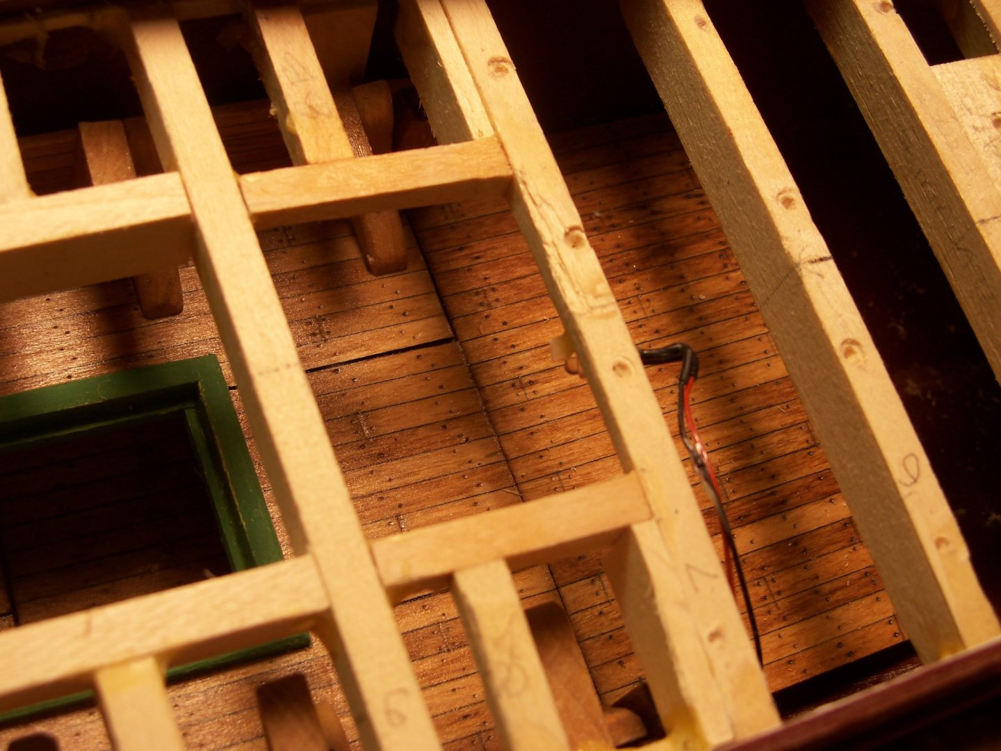
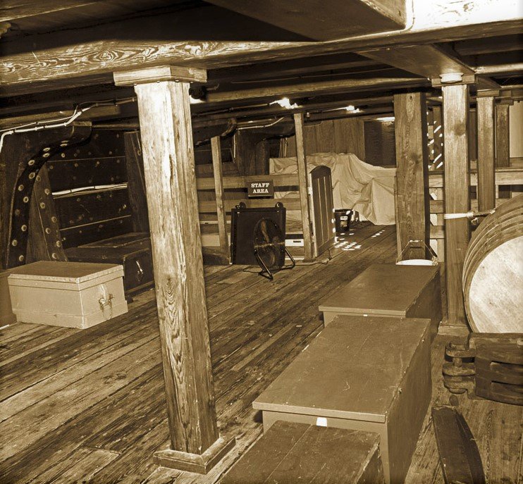
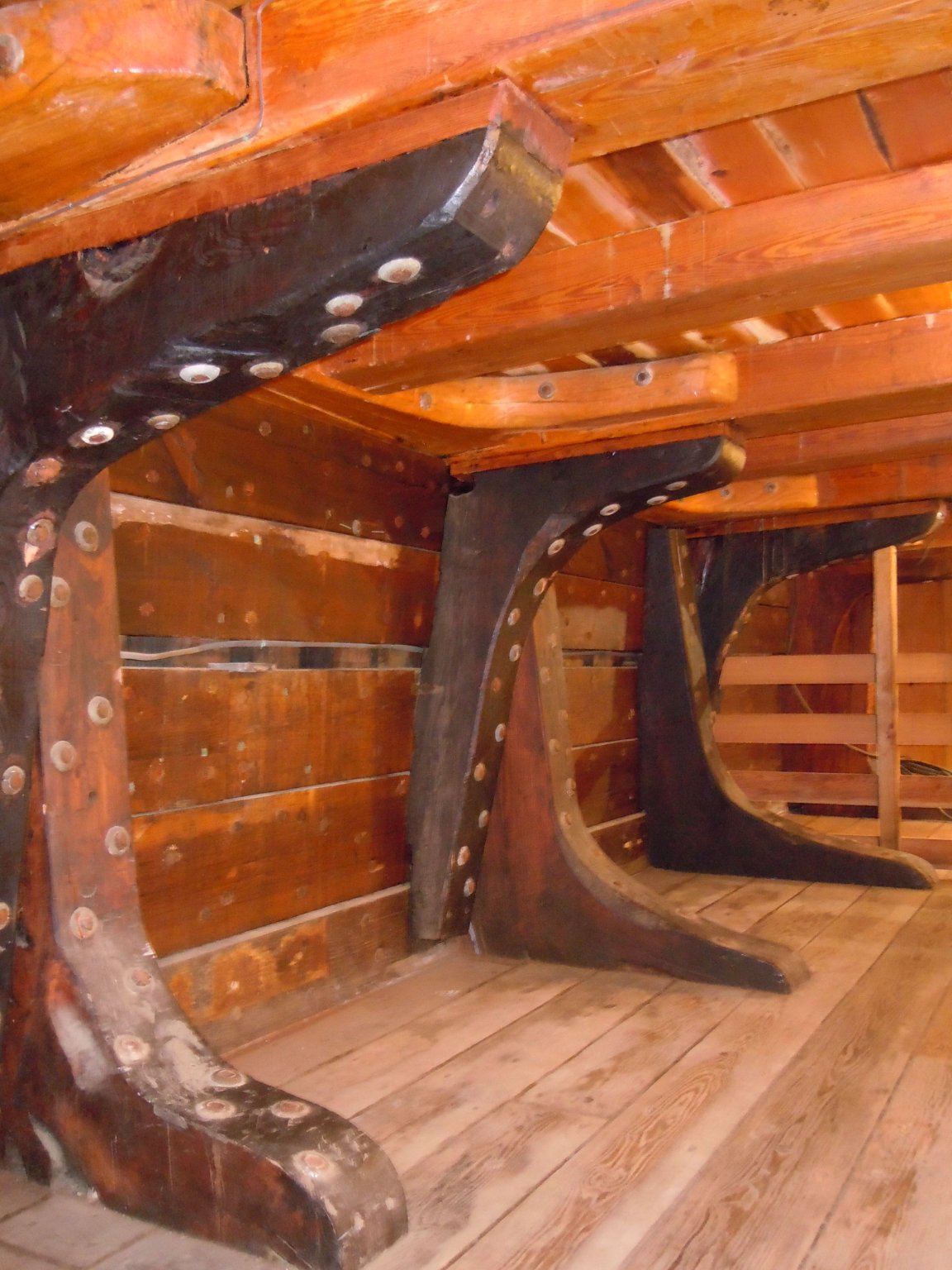
Some portions of the inner hull walls were still visible, so some stained scraps of decking were glued on to cover them up. While I didn’t know if there actually were partitions in the lower deck, even with the LEDs lit up, it would be hard to see them anyway. However, there were some support posts for the deck beams above that would be visible. In this photo below decks of the CWM you can see examples of these posts.
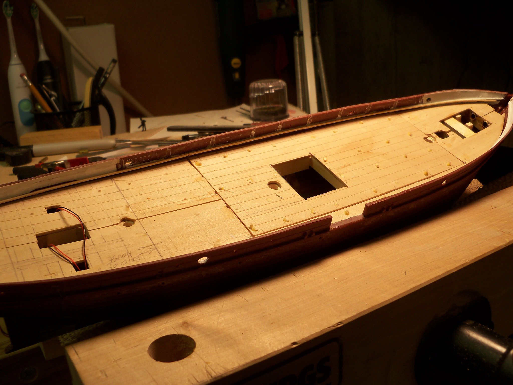
To represent these posts I used some stained 1/8” square basswood for the post and glued one end of to a strip of 1/16” x 3/16” stained basswood to represent the bearing plate at their base. Once the glue set, the bases of the posts were separated from each other. Then after sanding the base projection around the bottom to about 1/16”, the stain was touched up. Since the top of these posts will not be visible on the model, rather than fitting the top of the post to the bottom of the beam, I simply glued the top of the post to the side of a beam above and sanded it flush. I test fit the hatch grating placement on the lower deck to get an idea of how much room remained for other details and this is the result of my work at this point.
-
When I was still golfing and started having problems with my grip strength, I had some extra thick grips put on my clubs. This allowed me to maintain a firm grip on the clubs without trying to squeeze a too narrow grip. They were recommended at that time for golfers with arthritis. They allowed me to keep golfing for several years after that.
The same principal applies to my hand tools. When you're working with sharp instuments, you need to maintain a secure grip on the tool or risk ruining your work. (or your whole day with an injury) In some cases I just wrap the handle with some rubberized shelf liner and a rubber band as shown here. It's a cheap yet effective solution for me.

- thibaultron, Canute, Roger Pellett and 3 others
-
6
-
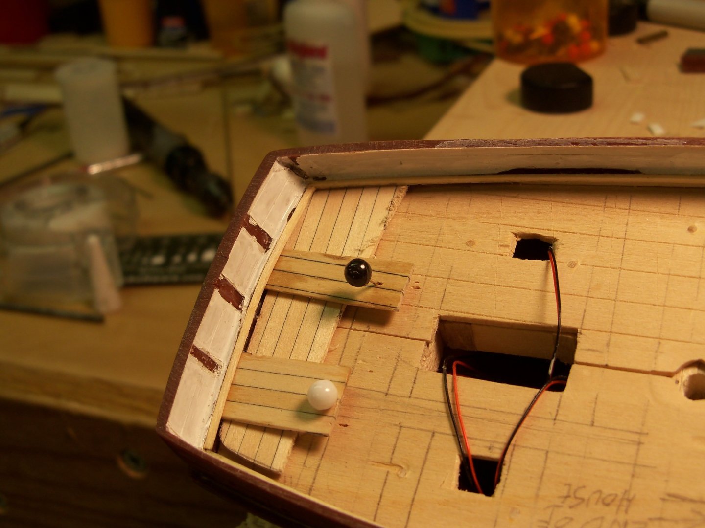
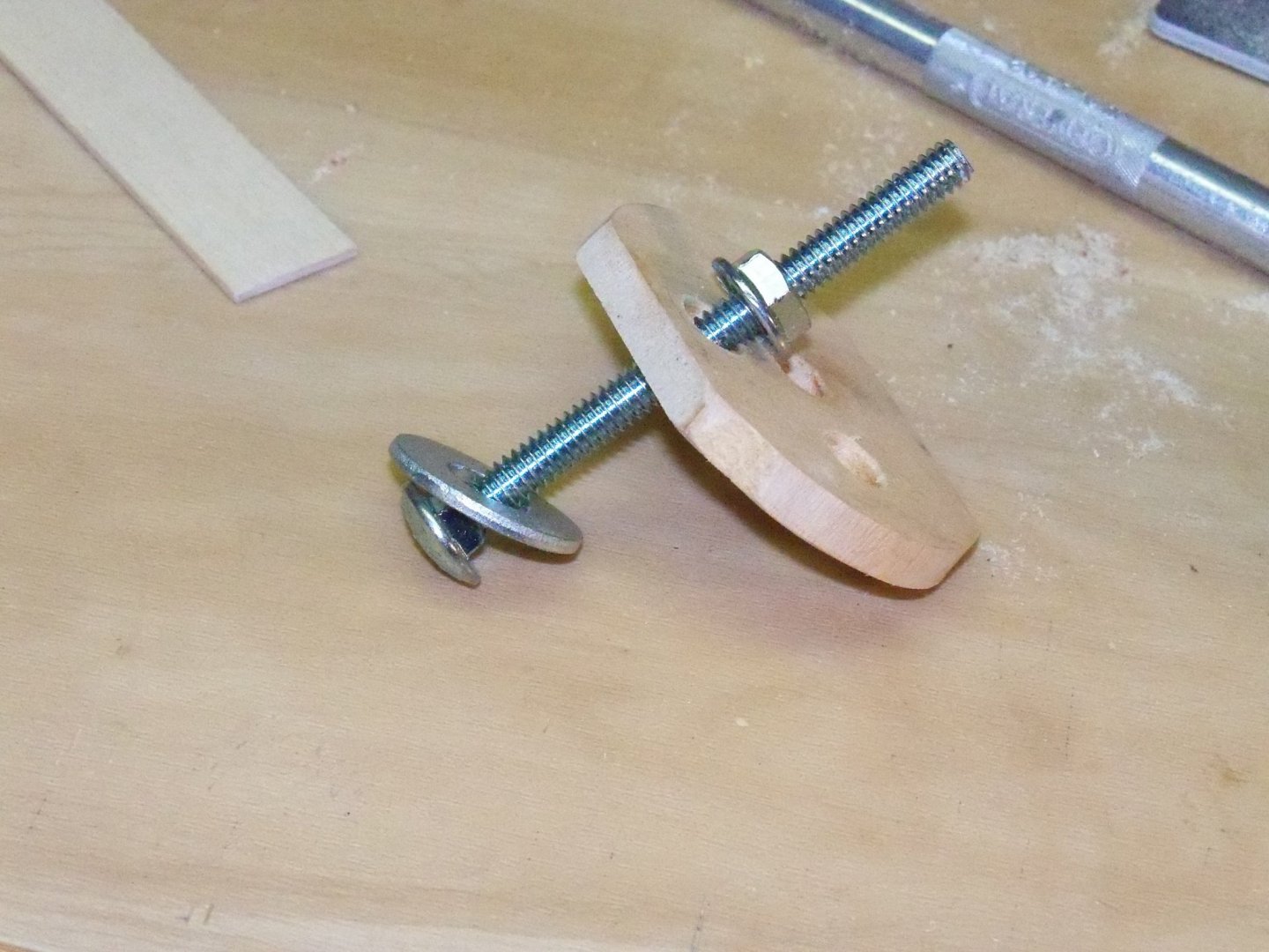
First, I cut and set two partial beams on either side of the new hatch opening and the two LEDs that were removed earlier were glued into their new positions. The clamp that was employed in the previous post was modified somewhat by adding an adjustable overlarge wood washer to better grip the main deck beams.
Now the lower deck had to be shifted to align the lower hatch with the one above. That turned out to be a very finicky job to handle, since I felt that I was several hands short for the job! I needed to slip two flat blocks of wood between the top of the angle braces and the bottom of the beams on each side, while at the same time keeping tension on the clamp to support the lower deck while maneuvering it into position and finally tightening the nut on the clamp. Perhaps if my custom washer was made of clear Plexiglas it would have allowed me to have a clearer view of what I was doing. (But as they say, hindsight is 20 20.)
Anyway, despite the visibility issue, the deck was finally maneuvered into position and tightly wedged into position against the sides of the hull. All of the wedges were set with carpenters glue by dipping a long bamboo skewer in the glue as it allowed me to reach pretty far down into the hull to put the glue right where I wanted it. Here is the wedged and glued hull below as it stood at this point.

Once the glue had set, I removed the clamp and I put in two partial beams on either side of the new hatch opening. The two LEDs that were removed earlier were also glued into their new positions.
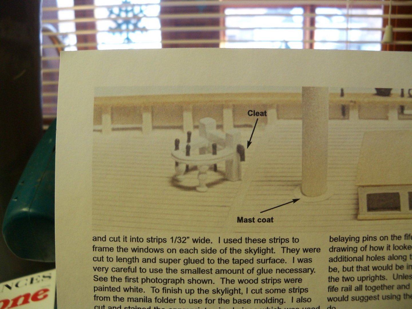
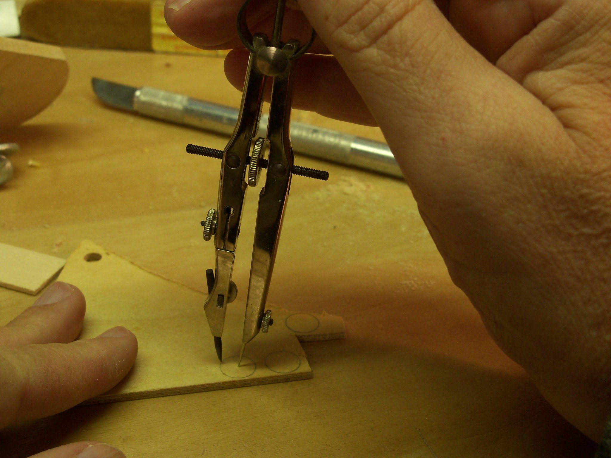
While waiting for the glue to set again, I decided to try my hand at making the mast coats, which are basically shaped like tiny washers. Using a small scrap of 1/16” plywood, a compass was set at the radius of the outer edge of the mast coat. I made sure that point was set fairly deep (to use it later as a center for the drill) and the circle was drawn.

The hole for the mast was drilled while I still had something to hang onto.
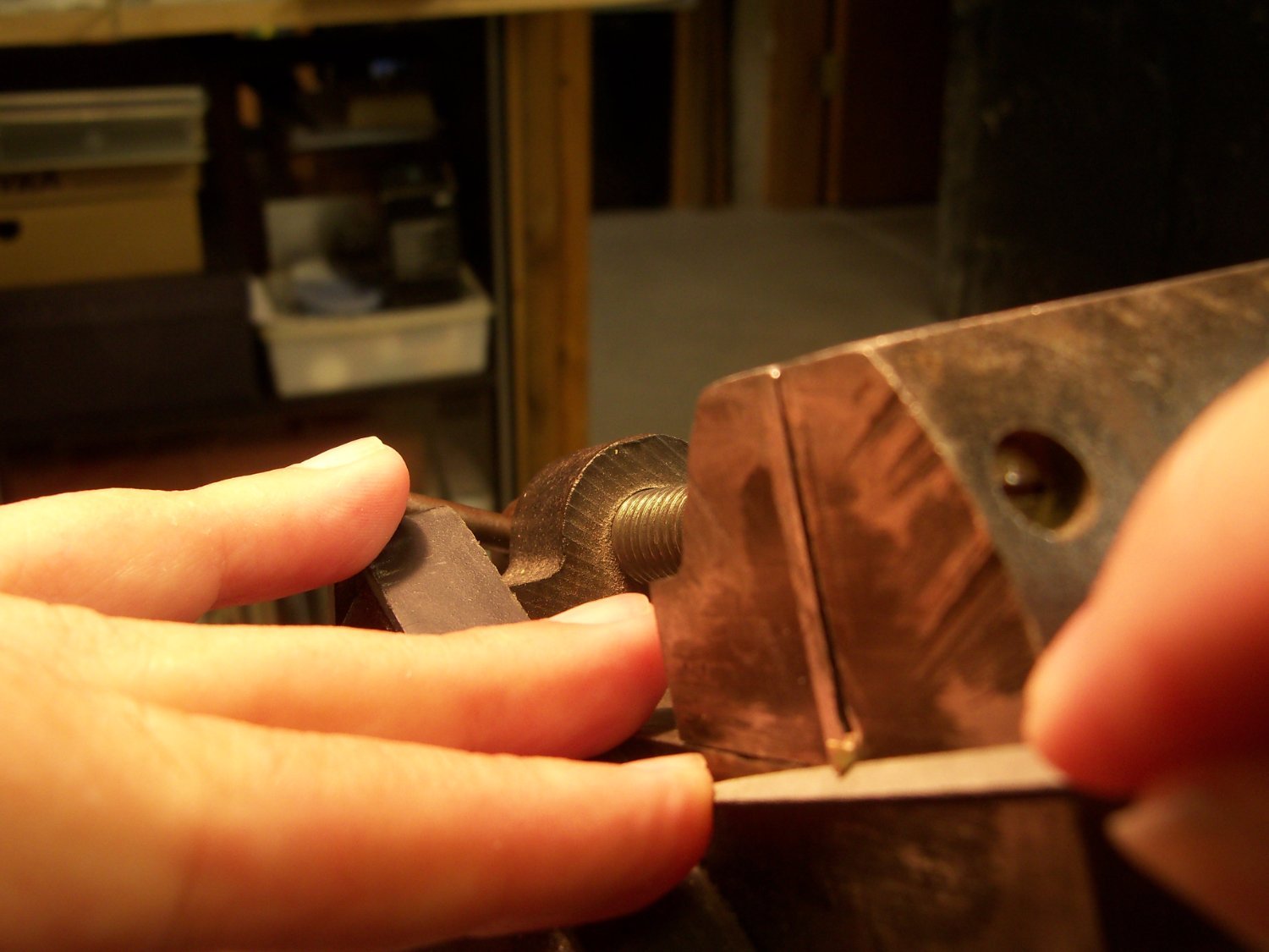
My scroll saw was then used to cut close to the line, leaving a narrow handle attached which allowed me to hold it while sanding right up to the outline with my disc sander. The handle was then cut off and the remainder of the circle was trimmed by hand to the line in my vise. Since the edges of mast coats were not flat, the disc was slipped onto the mast and using that as a handle, it was held diagonally against my small belt sander and the edge was given a slightly rounded over edge.
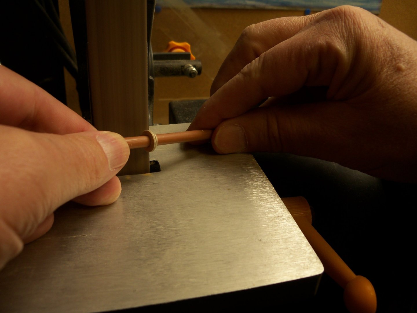
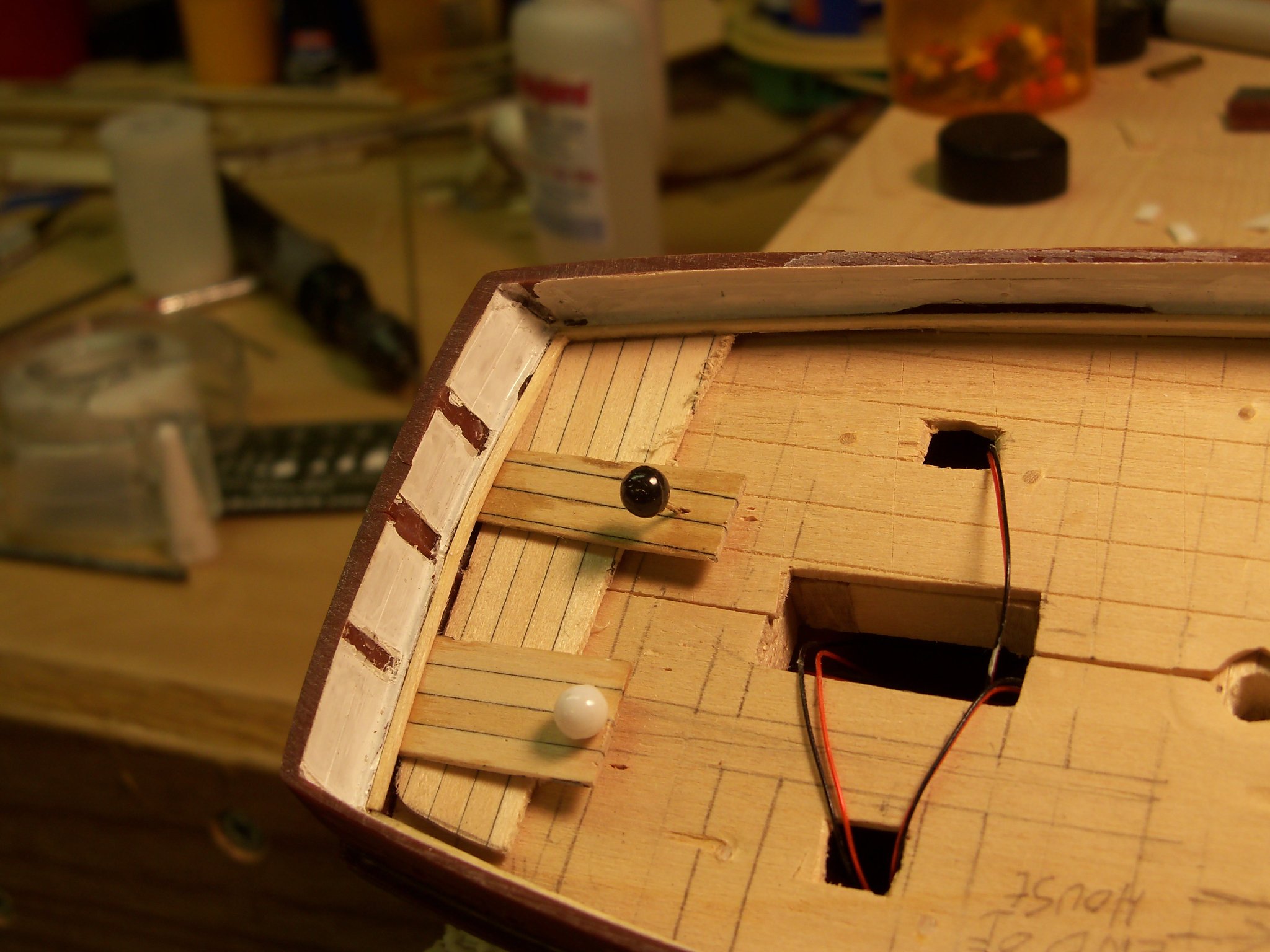
To finish the shape, I held the resulting washer down on a sanding stick and gave the bottom a bit of a bevel to match the rake of the mast so it will sit flush with the deck. Three are needed for the main deck that shall be painted, and the one for the lower deck will just be stained. I found that the main mast is also visible through the open hatch to the hold, so I guess I will make another stained one for there. Here is one of the resulting mast coats in position.
Next up on this operation was drilling the hole for the main mast through the lower deck. Very early on in this project, I had made up a template where the rake angles of the masts were marked. I dug it up and slipped a brad pointed drill bit that matched the diameter of the main mast through the upper deck. Matching that angle, the point of the bit was pressed into the decking below, marking the center of the hole. The bit was then carefully slipped through the hole in the main deck, centered on the lower deck mark, and drilled through on my drill press.
I encountered a slight problem, in that the brad point apparently didn’t project enough, and the bit was able to wander too far forward. (Nearly to the edge of the hatch.) This left the mast with way too much rake, and the heel of the mast couldn’t set in the pocket at the bottom of the hull.

A little more nervous surgery was needed with a rough round rasp to lengthen the hole into more of an oval shape (without destroying too much of the lower deck) until the mast heel could be set in the pocket. Luckily, the mast coat was just able to cover up my mistake.
-
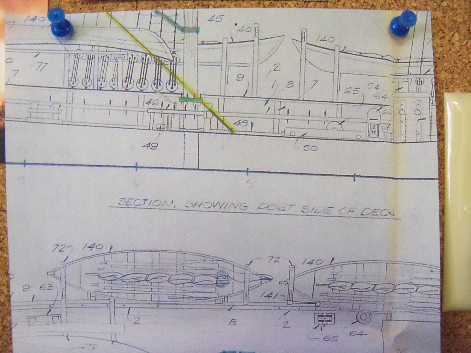
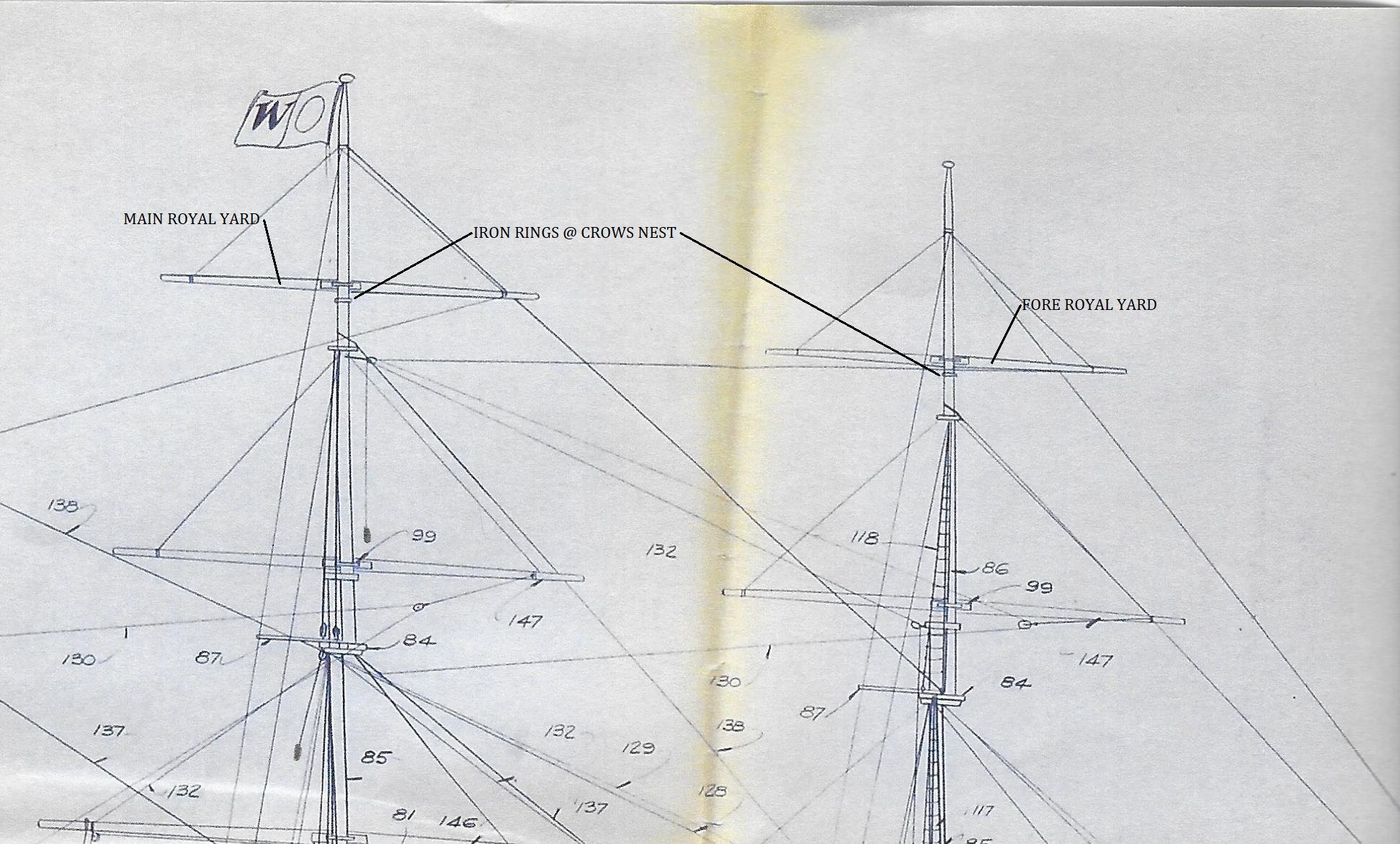
George, here are the plan details. You can easily see the conflict between the royal yards and the crows nest.
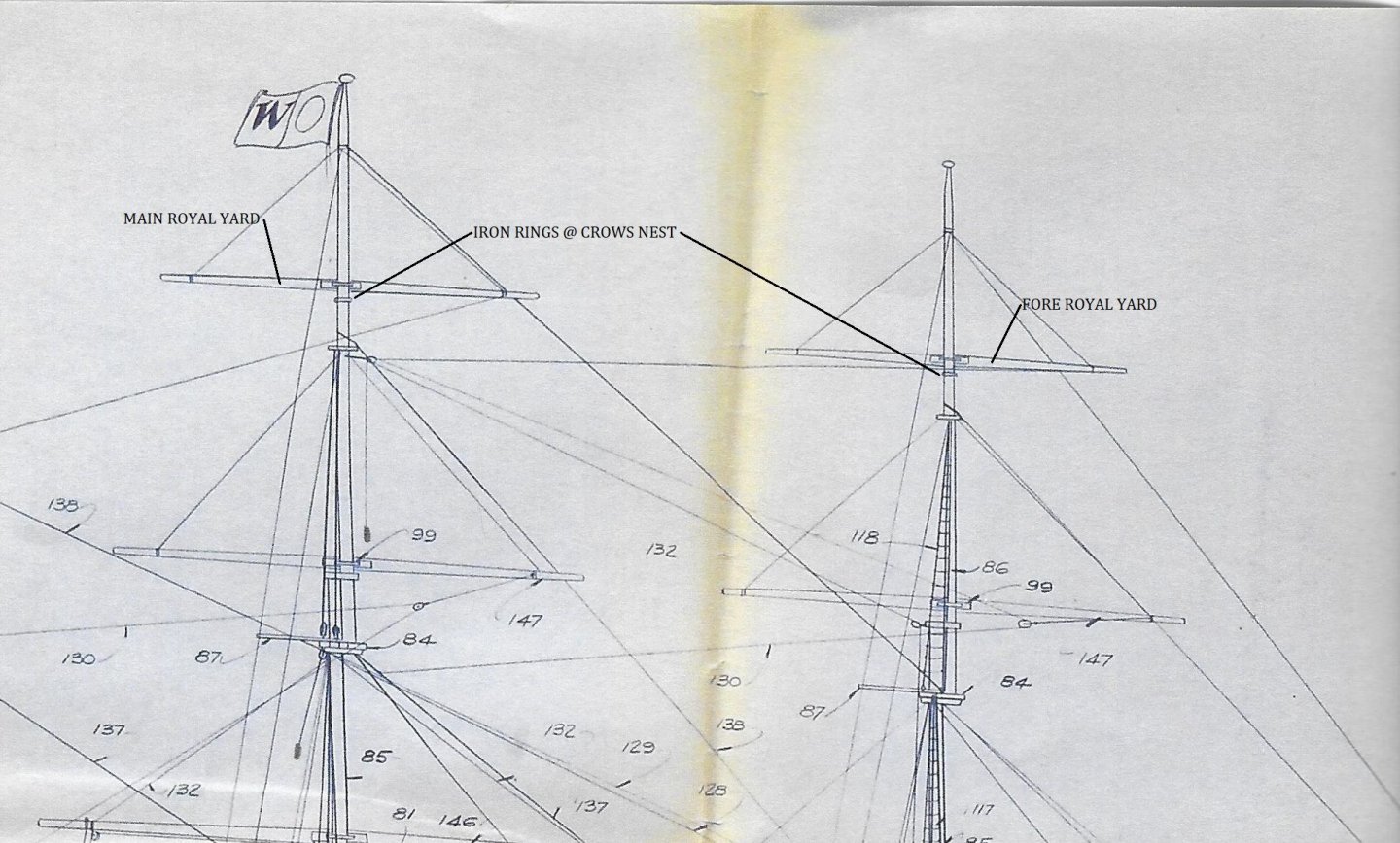
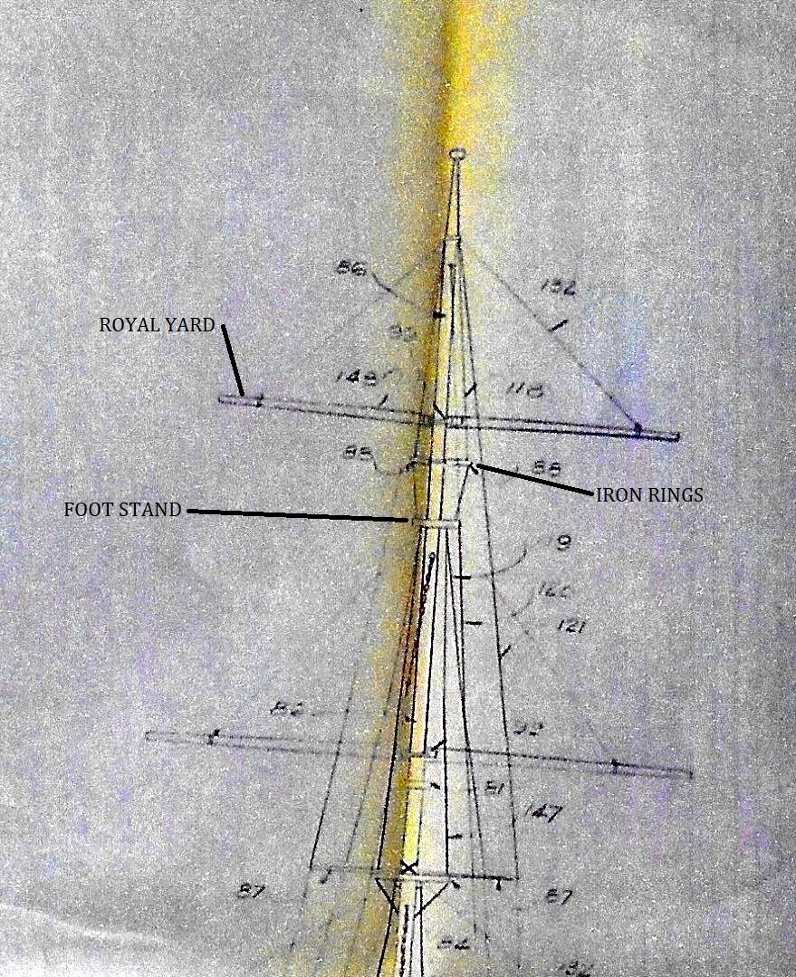
The yard and or sail would be right about eye level with the lookouts.
-
On 2/4/2021 at 12:55 PM, gak1965 said:
looks like plenty of spar to mount a royal.
Hello there George
While there appears to be plenty of mast above the topgallant sails, this ship was a whaler, and as such had a pair of iron rings mounted on both the main and fore mast commonly referred to as the "crows nest". That is where the crew stand watch to spot their quarry. To add a royal sail above the topgallant would have made it quite difficult to work that sail as the nest would prevent the spar from turning, not to mention the fact that it would interfere with their primary task of sighting the whales.
Although it may have been possible to move the nest above that extra sail, that would just have increased costs. Since the minor increase in speed that it would provide was not much of a cost saver, the owners would not think that it would have been worth it. I think that they were primarily concerned with their profit.
As far as the plans go, they were really lacking in details, which is one reason for my going to such lengths to find more accurate info.
Dave
-
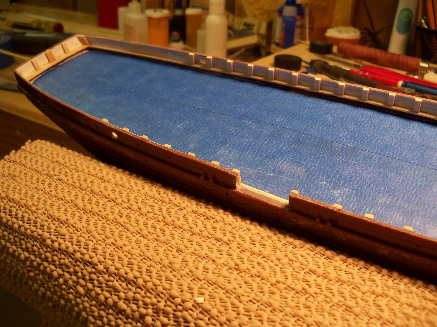
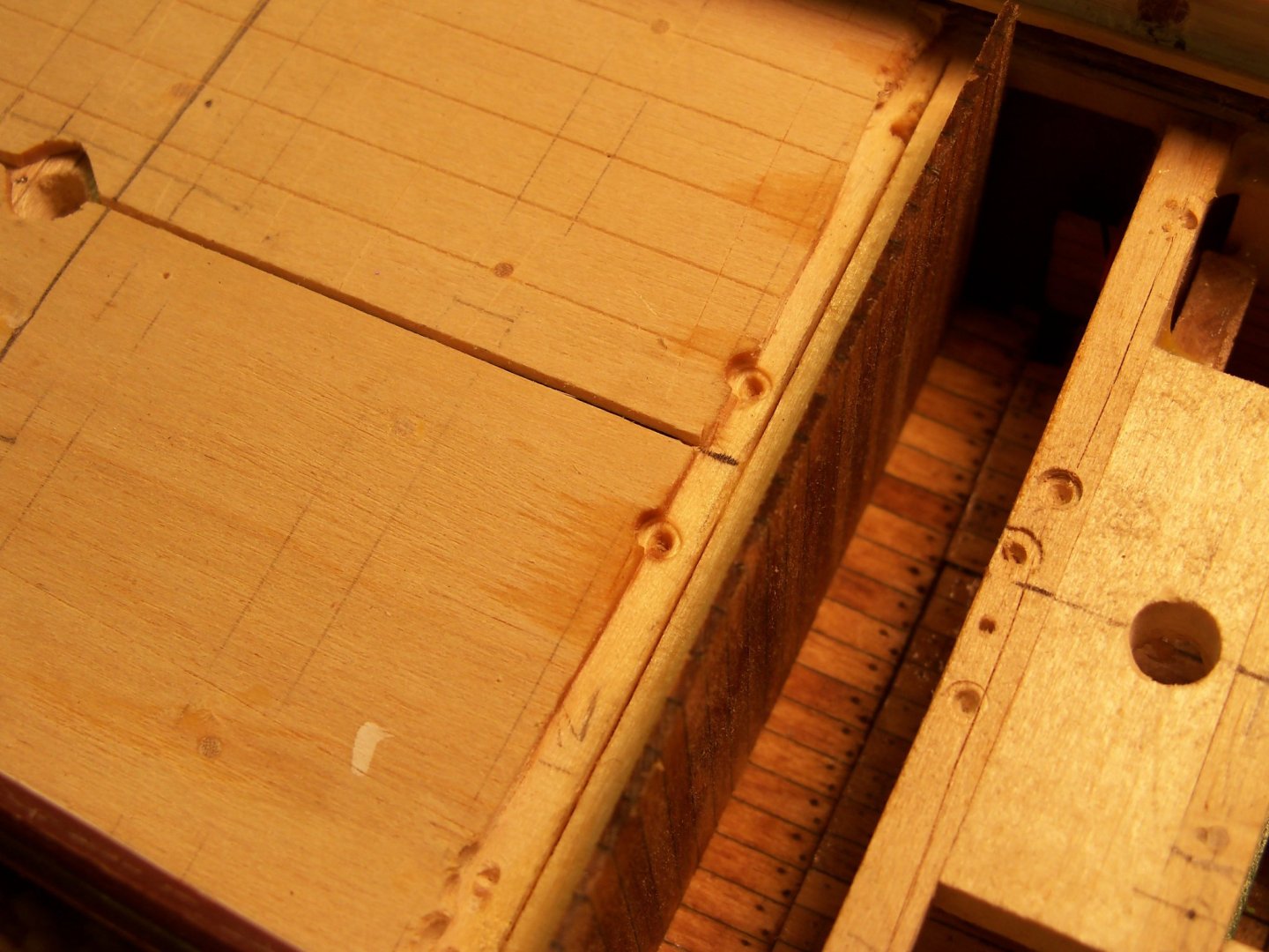
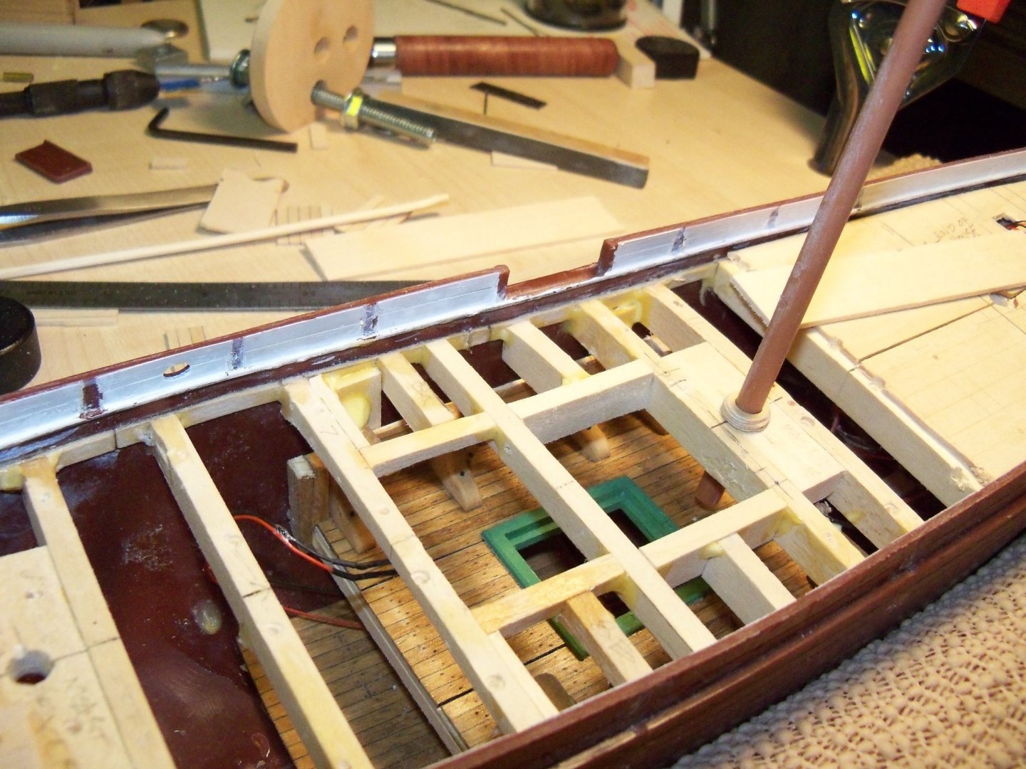
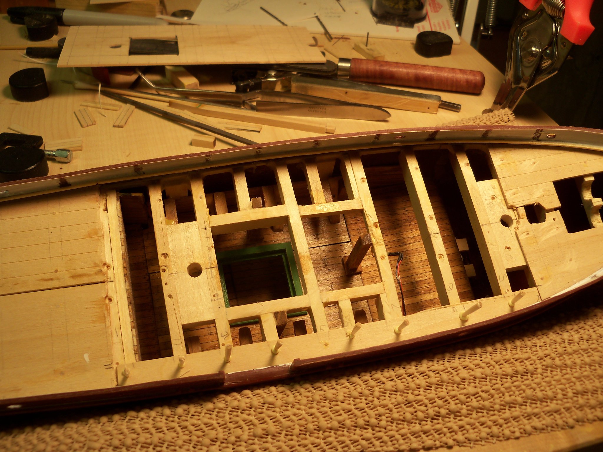
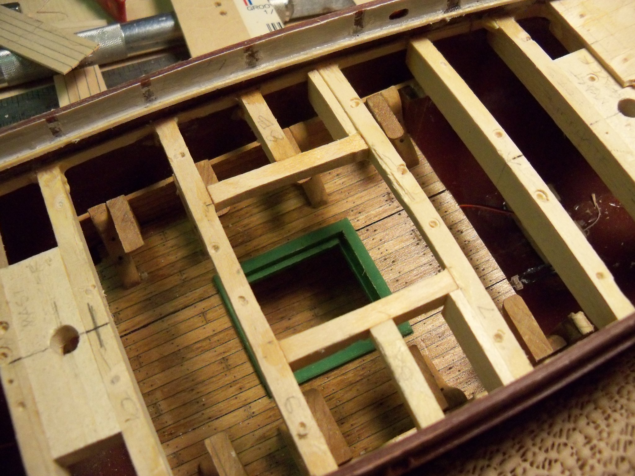
Well now I’m really up to my neck in it, as I returned to the major surgery of moving the main hatch. The first order of business was to remove another section of the false deck to allow me to get a little better access to the beam aft of the main mast so the lower deck and hatch can be suspended from it. This is how it looked before starting the changes.
Once that was done, I worked on cutting the lower deck and hatch free from the beams above. At first I was perplexed about how to do this since the posts were really in a tight spot. Getting any kind of saw blade in there just wasn’t possible.
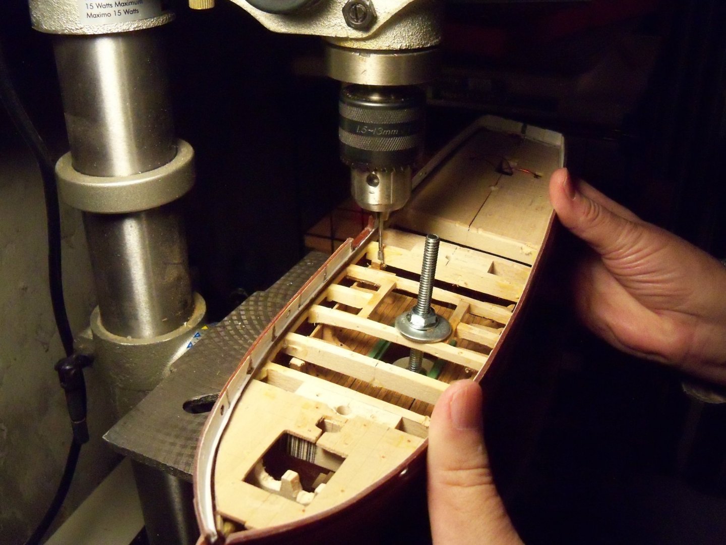
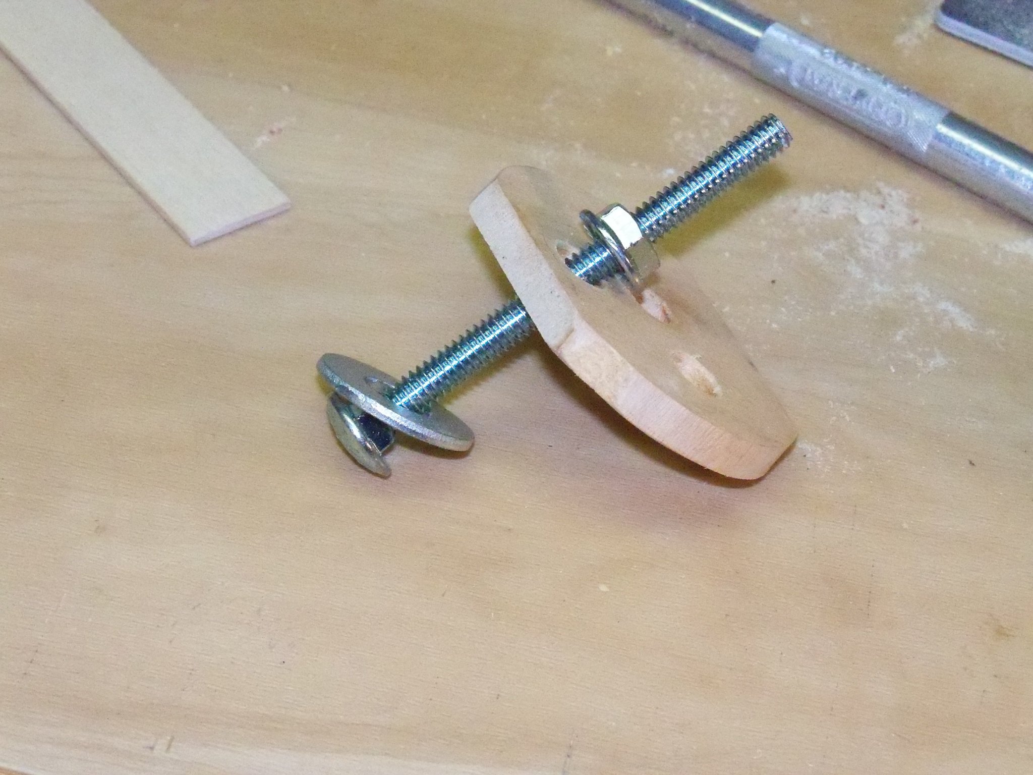
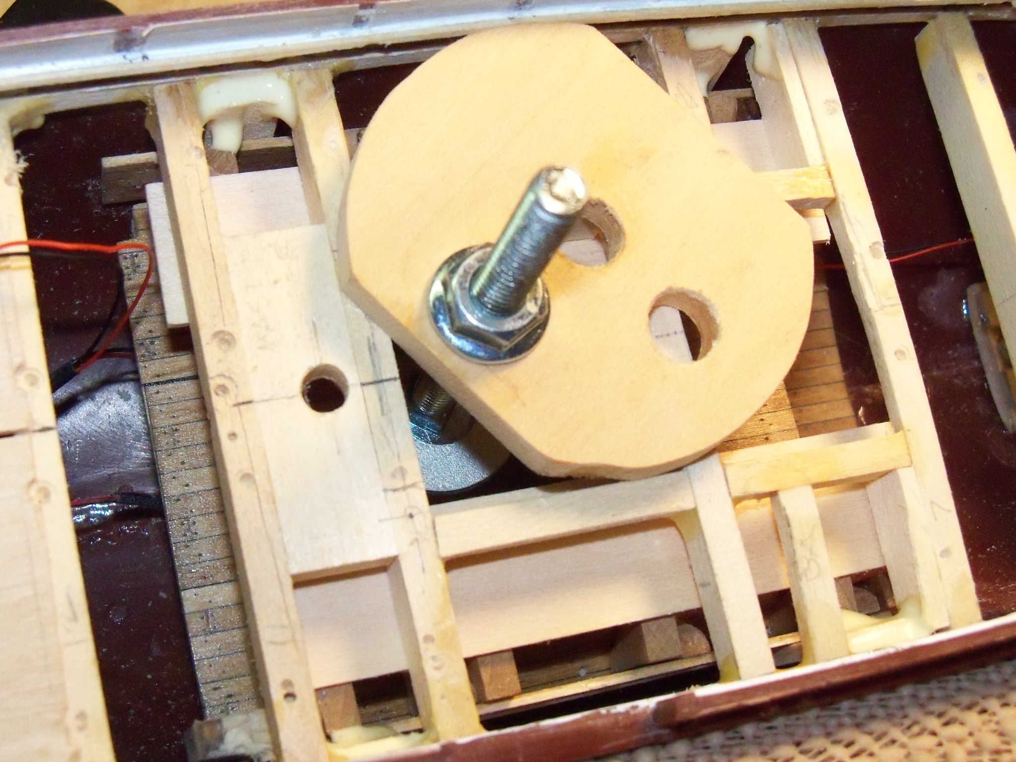
A Dremel router bit with a long shaft was chucked in the drill press and the table was raised to the point where the bit could just reach the top of the suspending posts. I assembled a homemade clamp with a bolt, a large pair of flat washers, and a nut. The washers were large enough to get some purchase and yet just small enough to pass through the lower hatch. Hooking the lower washer around the bottom of the lower deck, the top washer did likewise on the deck beams above and the nut was tightened to hold the deck in place. Here is my set-up for this operation.
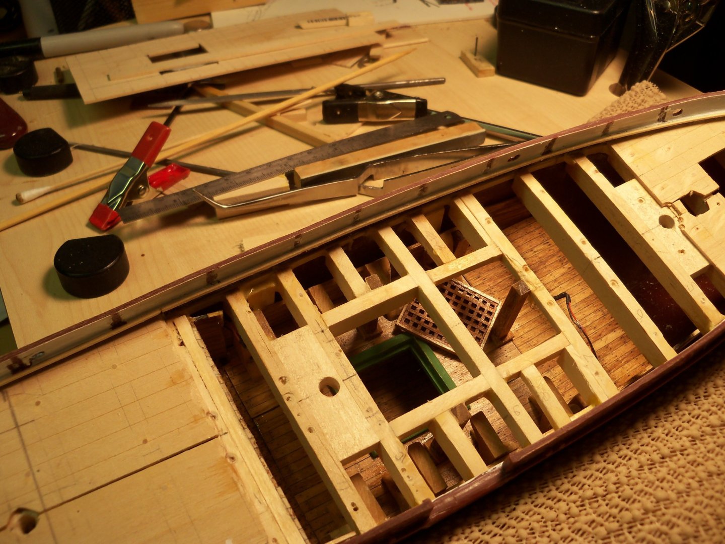
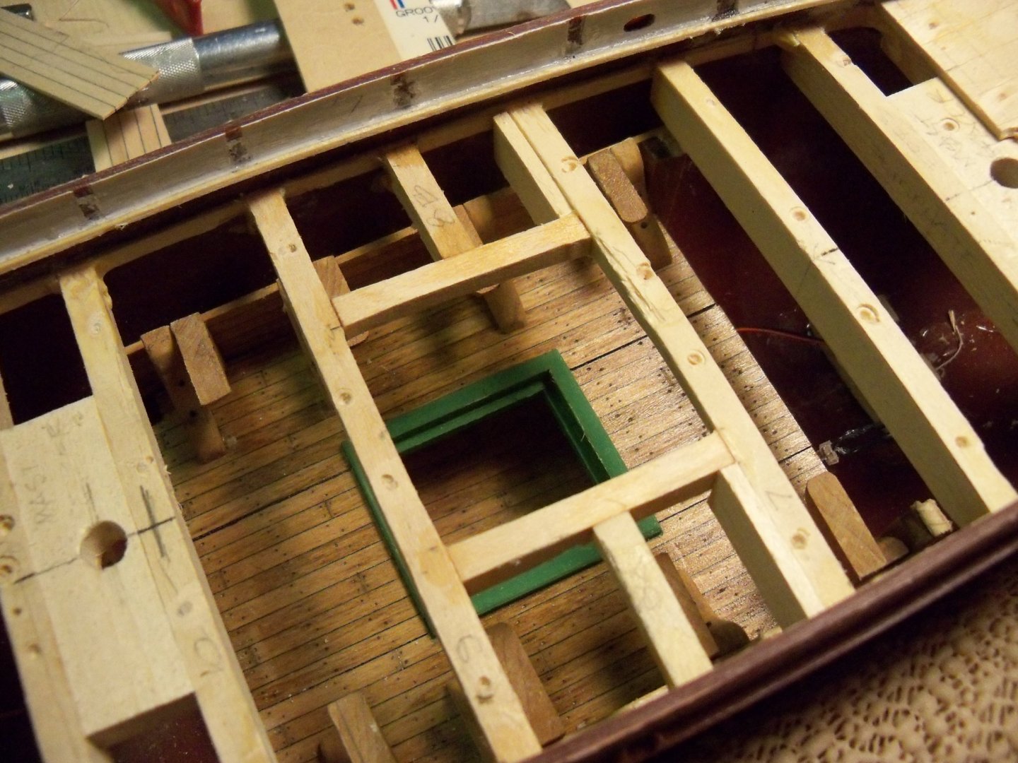
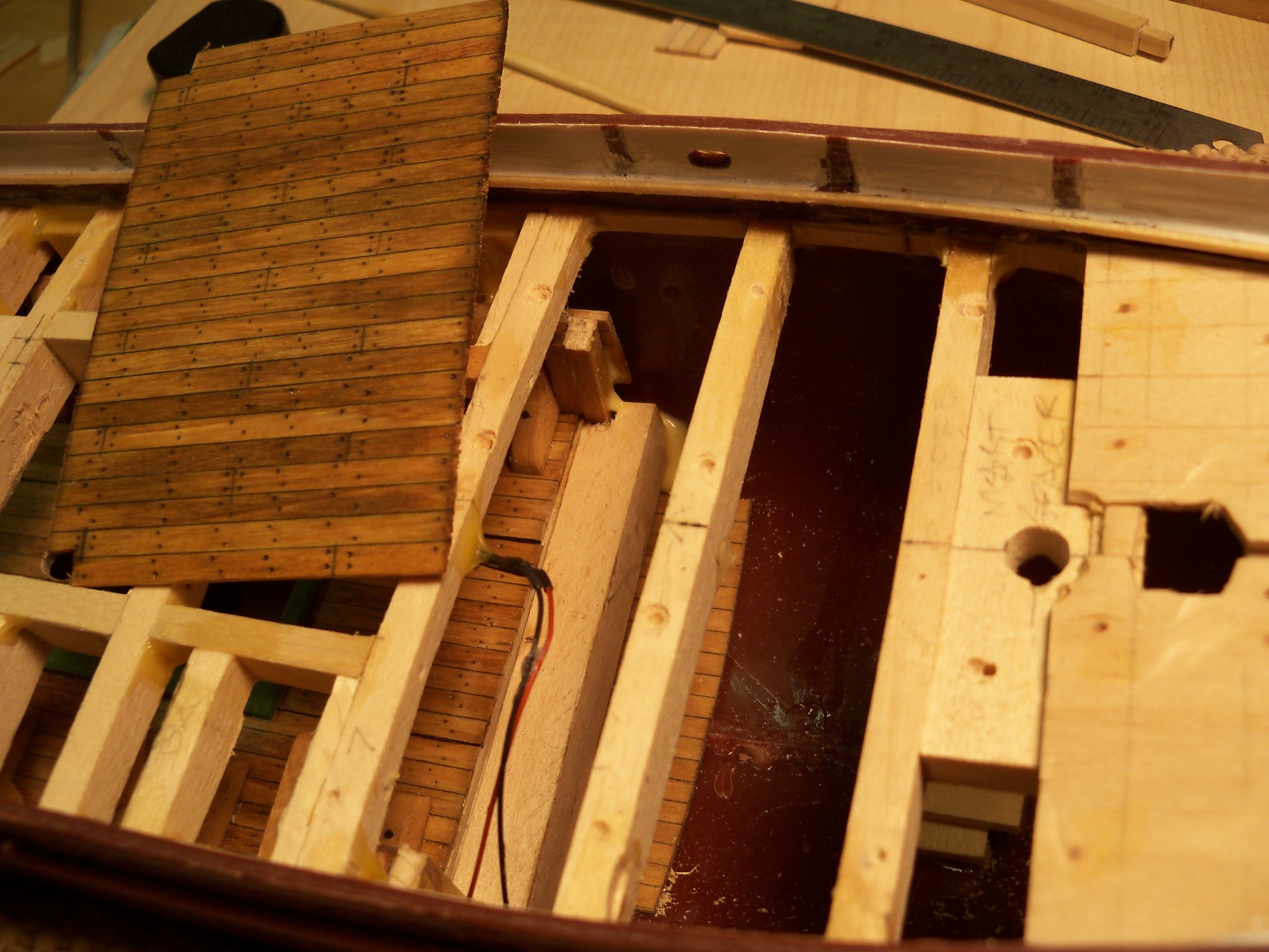
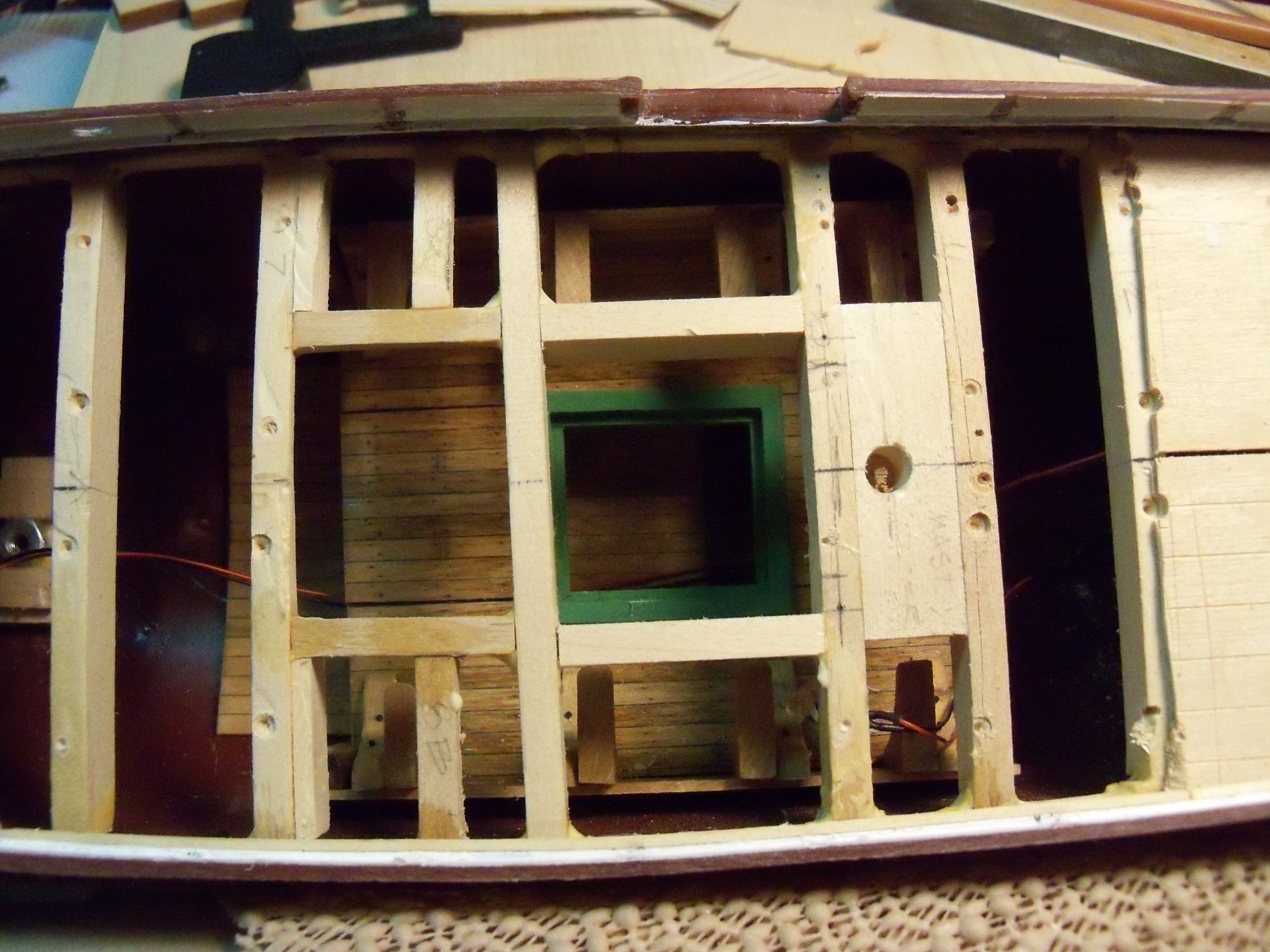
By using the router bit in the drill press it allowed me to move the hull with two hands braced by the drill press table. I chewed off the tops of the posts with light passes allowing me to keep the bit under better control while doing this freehand routing. Once the posts were almost completely routed down, I used an Exacto blade to release the lower deck to allow me to shift the deck to its new location as shown below.
Luckily, the width of the hull at this point allowed me enough clearance to shift it aft without needing to further modify the lower deck.
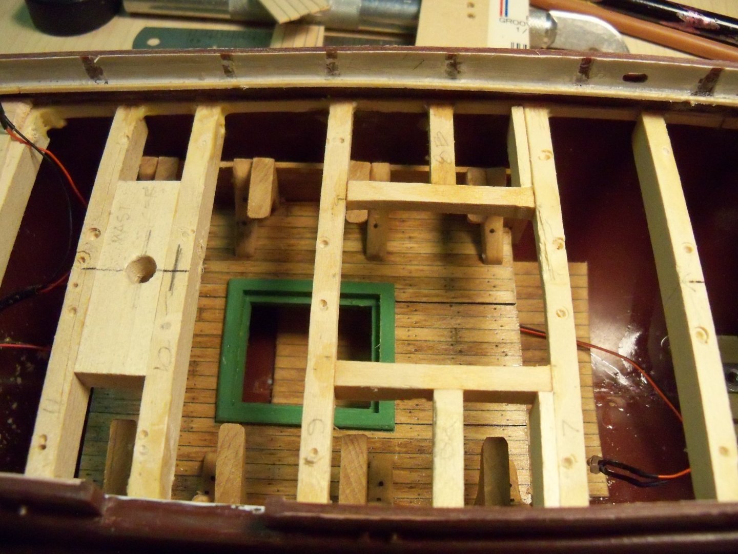
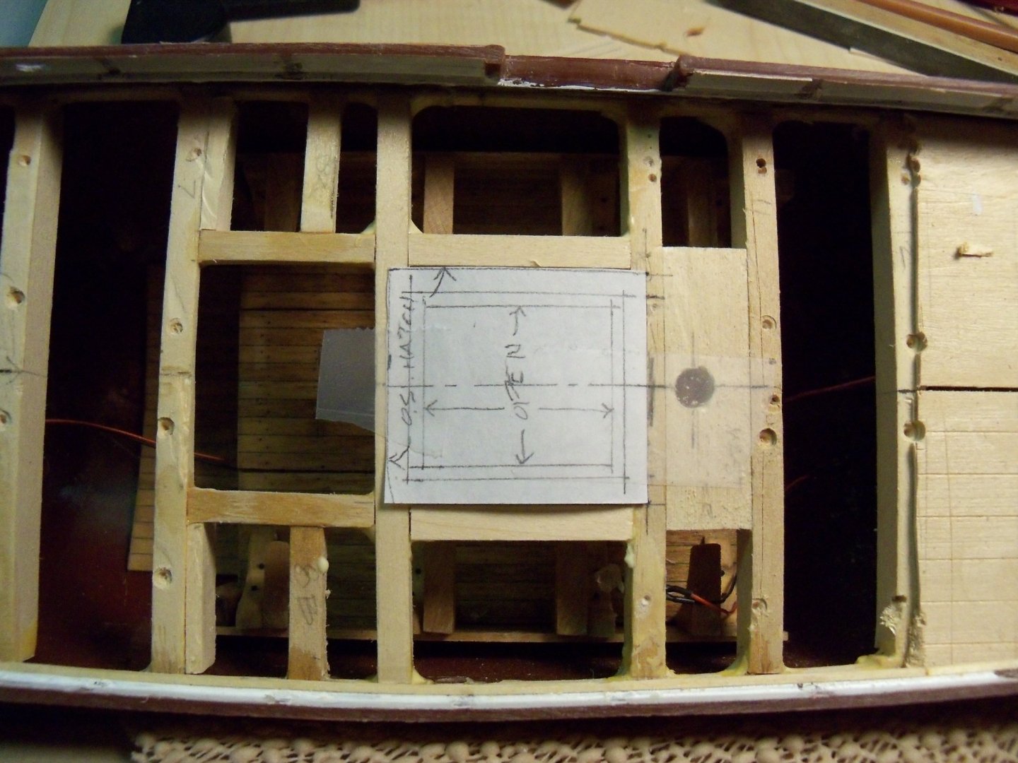
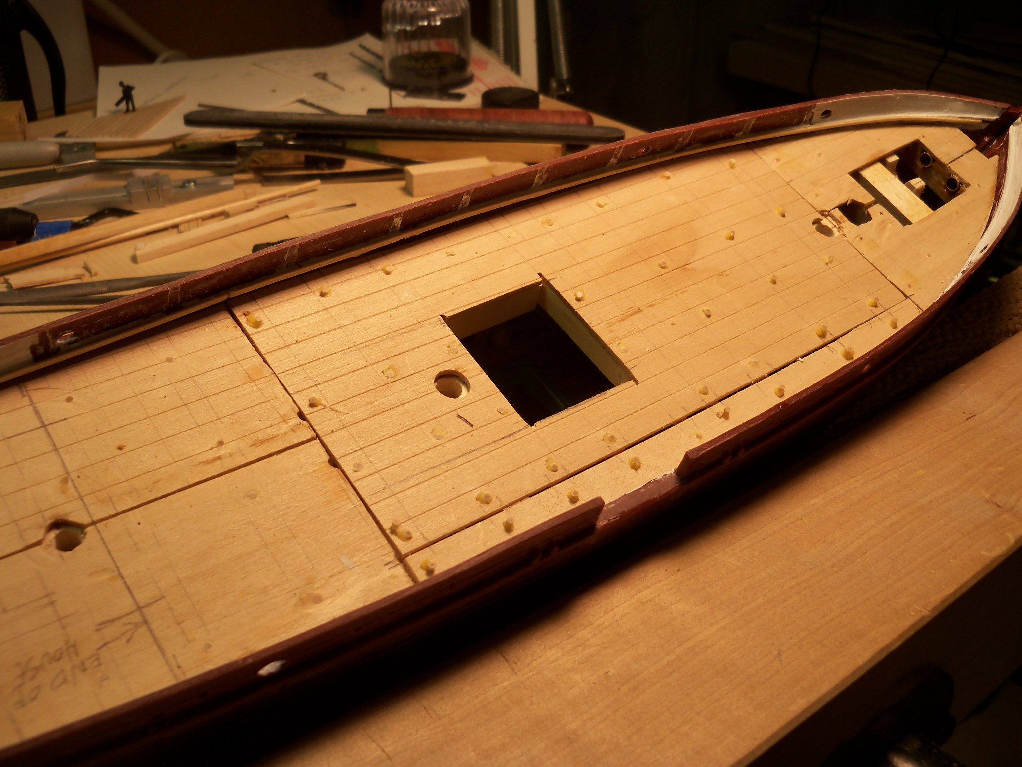
I made a template of the new main hatch and taped it in place so I could see what adjustments were necessary to the deck beams. The aft end of the hatch would butt up to the face of beam #10 at the main mast and beam #9 needed to be moved to the forward edge of the new hatch.
The two longitudinal beams were shortened to accommodate the new location of beam #9. Unfortunately beam #9 had to be discarded since the only way to remove it was to rout it out. So I cut a new beam and used wood glue to attach it to the side ledgers and support the remainder of the cut-off longitudinal beams. I cut two new longitudinal beams that ran between beam #10 and the new beam #9 and glued in them in position for the new sides of the hatch.
I will let the glue cure overnight before doing any more rough work on it. I taped the template in place so you can see exactly how much the new main hatch location has changed.
The next phase will be to shift the lower deck and its hatch to match the upper hatch location.
-
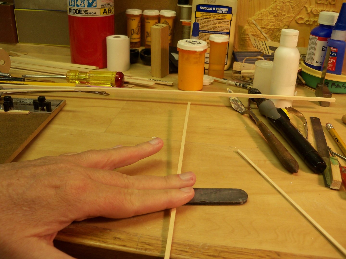
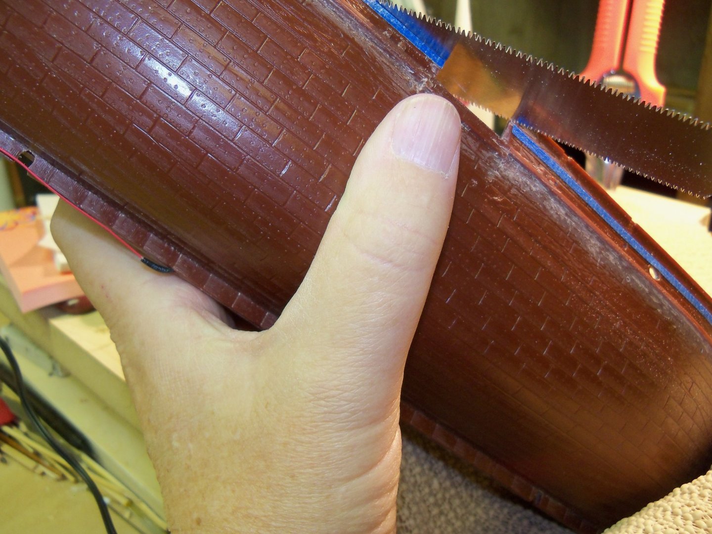
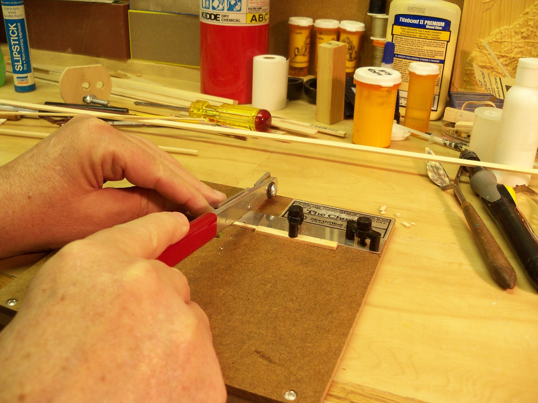
After trying numerous solutions for cutting the bulwarks down with every tool at my disposal, the one that I settled on was to cut it down with a special hand saw and various sanding tools. The first step was to cut narrow strips of painters tape to make my cut line more readily visible. While this operation in itself presented me with a problem because of my weakened grip which made holding my cutting guide still while cutting the tape with a #11 Exacto blade. Slicing my hold down fingers wasn’t something that I was looking forward to, so I just clamped the guide down to the table as show below before making the cuts.
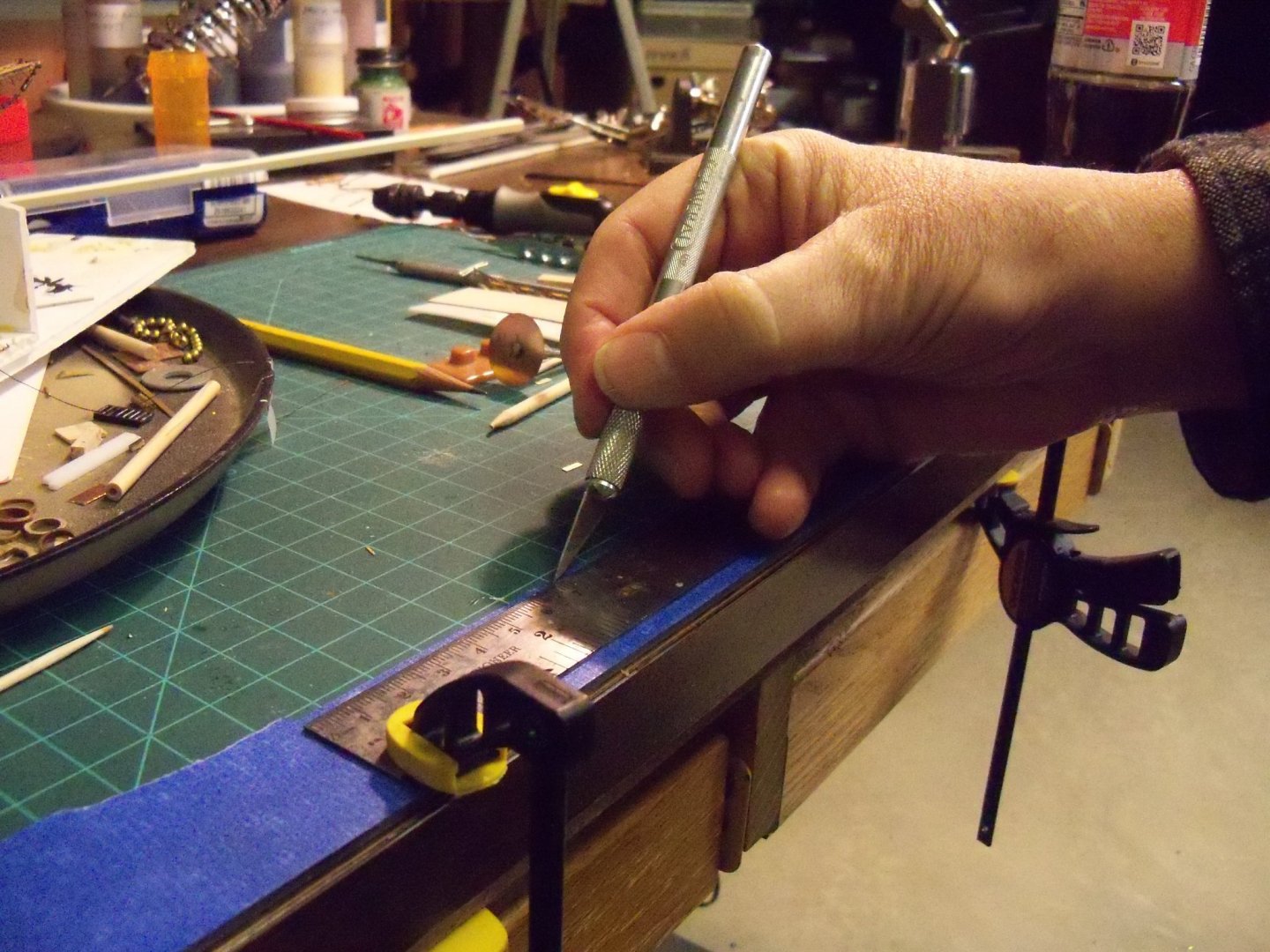
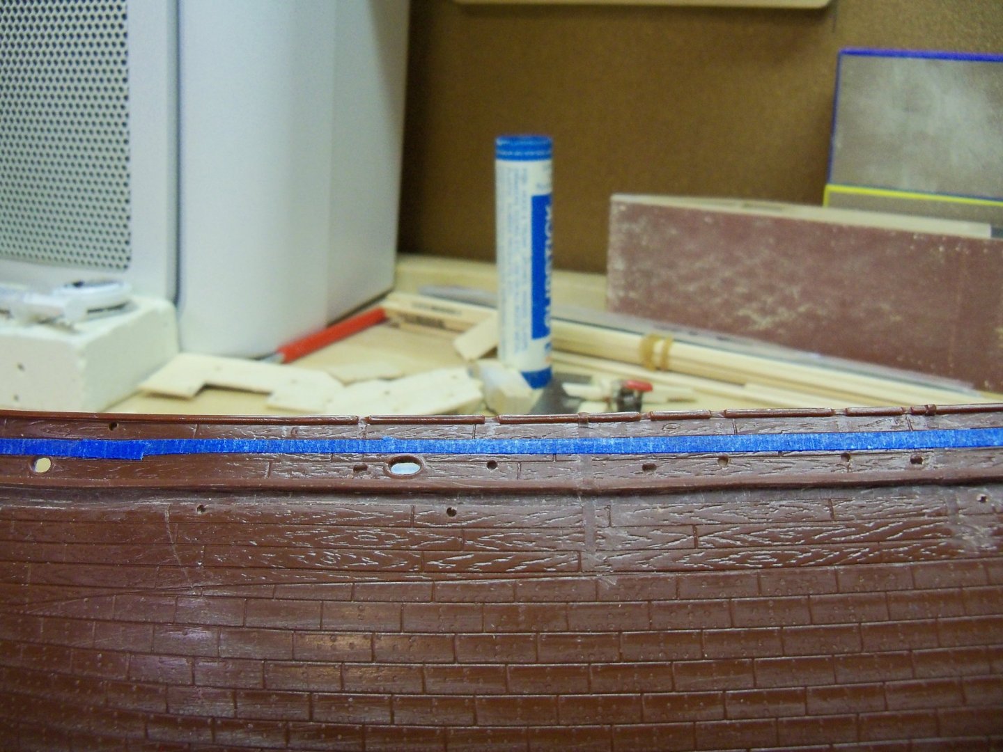
As it happened the height of the bulwark that I needed just happened to align with the bottom edge of the top plank of the inscribed plank on the model. That made it a simple matter to align my tape with the intended cut line as shown below.
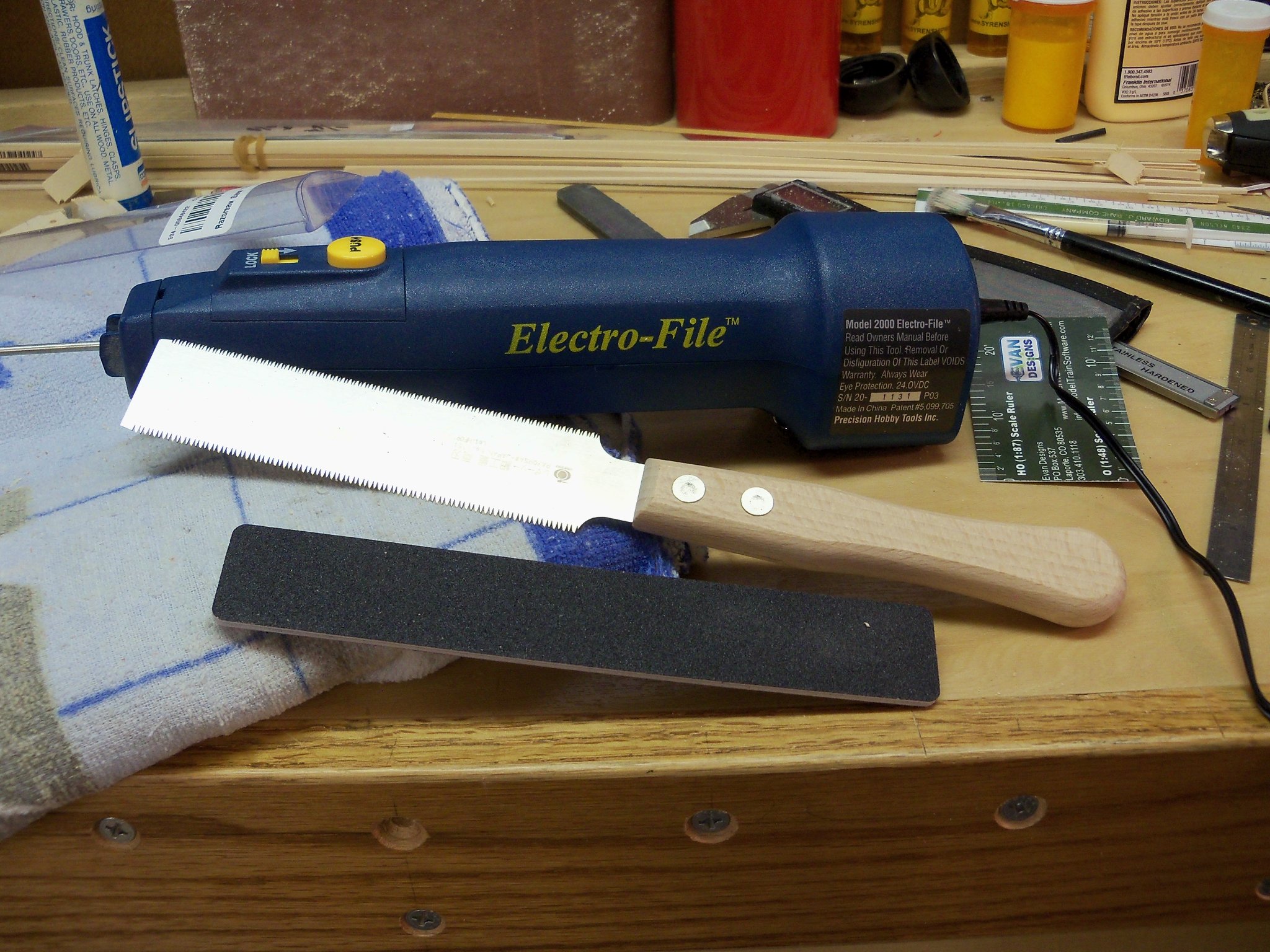
These tools shown below were chosen for the operation.
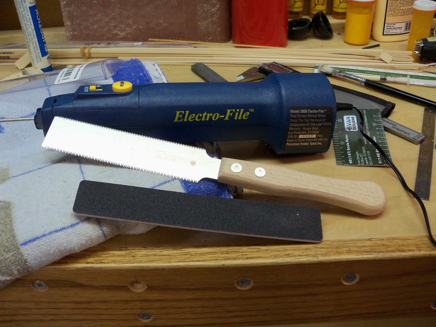
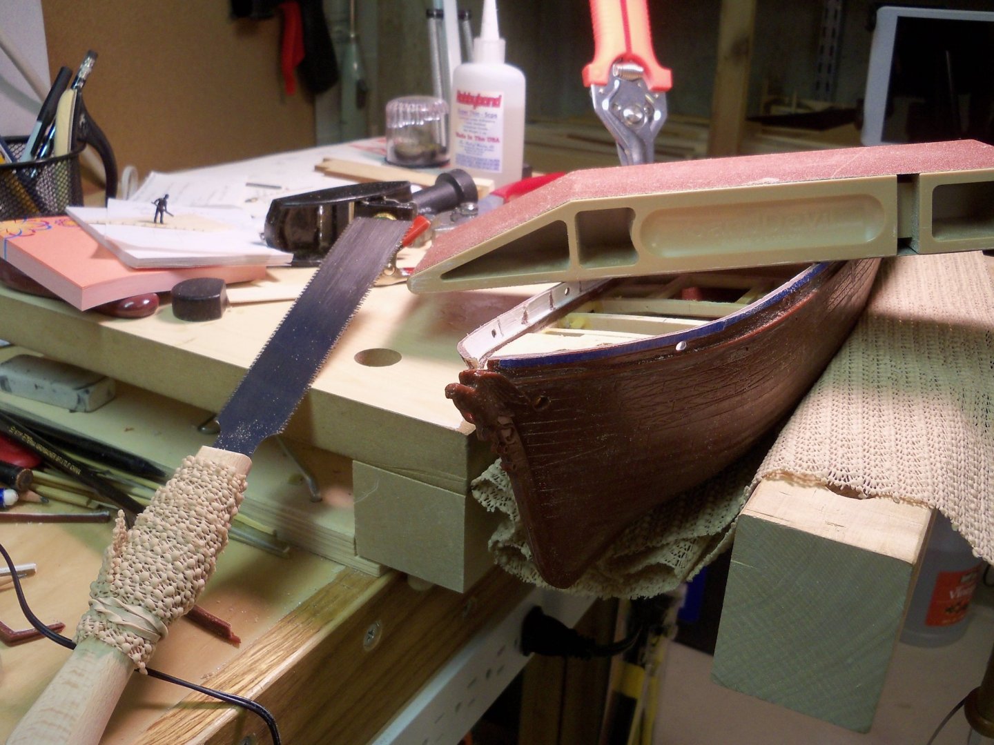
The thin flexible bladed Japanese saw was selected because of the teeth that were both fine and made to cut on the pull stroke which made it easier to follow my cut line. The saw itself cut pretty smoothly, but the hardest part of this operation by far was trying to hold the hull steady enough to follow the line. I ended up opening up my vise for a loose fit and used some rubberized shelf liner to give me a non-slip surface to lean the hull on.
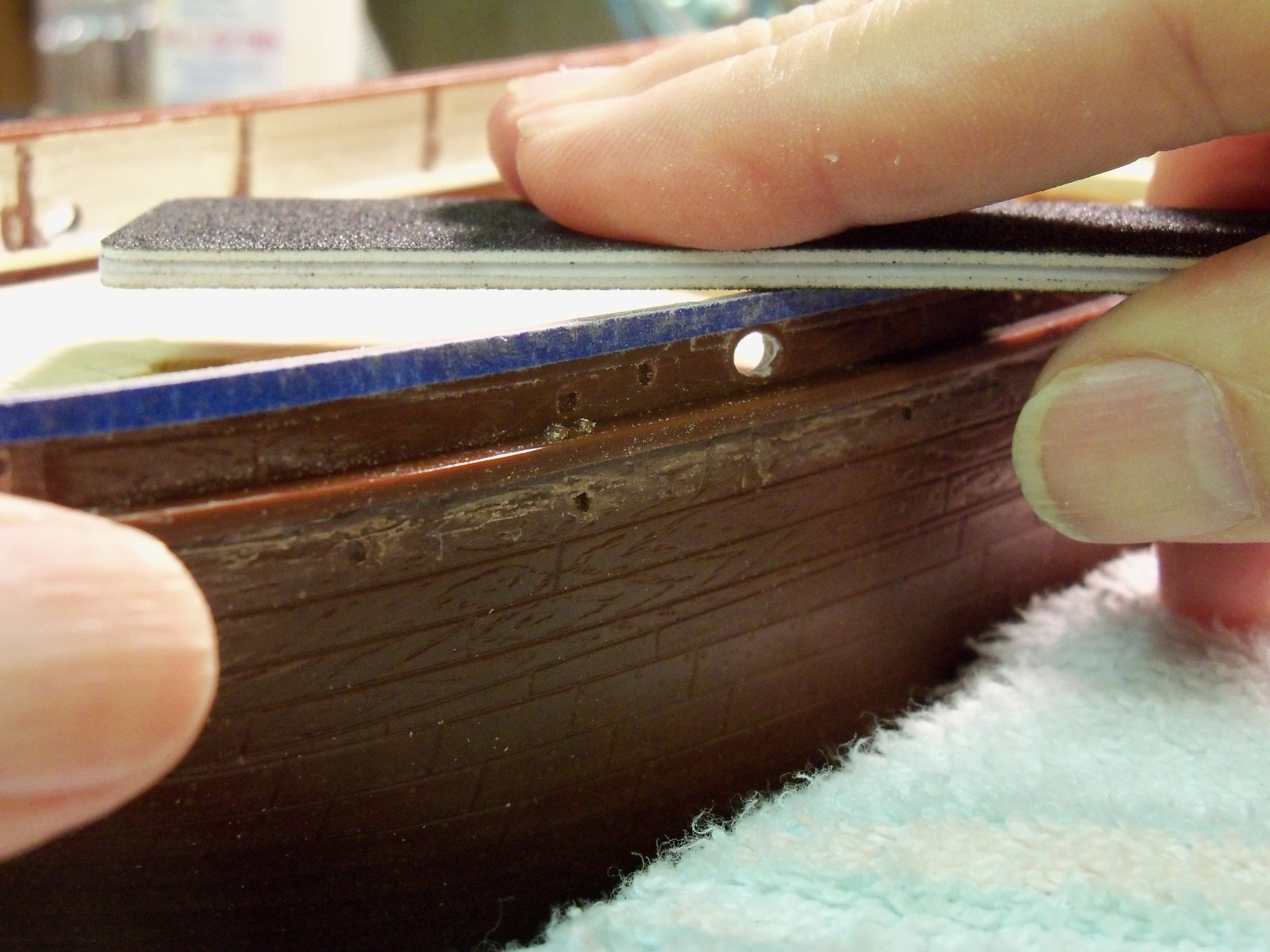
Not totally comfortable with my sawing skill, I made sure to stay just short of the guide line so I could sneak up on it with various sanders. My grip strength was a hindering factor once again, so I wrapped a strip of the rubberized shelf liner with a rubber band around the handle and that helped quite a bit. The Electro-File in the photo was then employed to quickly sand down the irregularities before switching over to that wider flat sanding stick.

The final step was using this wide flat sanding block that could span across the whole width of the ship to make sure that the top of the bulwark was flat and even for the later addition of the main cap.
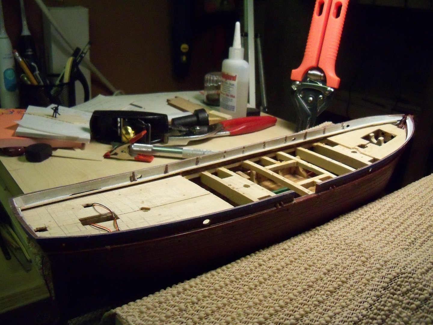
Here is the result of the whole procedure. I was quite happy with the results.
- JesseLee, Bruma and Roger Pellett
-
3


a drafting tool or paper weight
in Modeling tools and Workshop Equipment
Posted
It's actually a drafting tool. Several of these hold a flexible spline in place and used for drawing curves.