


BETAQDAVE
-
Posts
5,367 -
Joined
-
Last visited
Content Type
Profiles
Forums
Gallery
Events
Posts posted by BETAQDAVE
-
-
I’ve built and sold several tall ships in both plastic and wood before. But having reviewed the kit directions and Chuck’s practicum, I decided to look for more info on this ship before going any further. I also read How To Build First-Rate Ship Models From Kits by Ben Lankford and decided that I wanted to incorporate some improvements to the kit as there seemed to be some uncertainties about many of the details of the Phantom anyway.
For one thing, since having searched quite a bit for info on these pilot boats in that era, it seemed that since almost all of them had one or two small boats onboard to transfer the pilot to the ship in need, I decided to add one to this ship. I found some pilot boats had what they referred to as pilot yawls, which had partial clinker built planking. Then I looked for and found info on it and decided to put one of these on the deck. So far I haven’t worked on this yet.
After recently reviewing the impressive scratch build of the Eagle by Pete Jaquith on MSW, I found that a lot of the modifications that I had already added to my build were not really as original as I once thought. I took the solid carved hull, removed the bulwarks, and shaved the hull down to the inside of planking as far down as the line of the copper sheathing. Then I installed the shear strakes, notching for the timberheads thru the strakes and into the hull. When I finished installing my hull planks, I applied some strips of my stock basswood for bulwarks and put in the scuppers by omitting the bottom plank at the openings.
On reflection later, I think that I should have put a bit of a bevel on the edges of the planks so they would stand out better. Once it was painted black, it was hard to discern that they actually were individual planks and not a solid hull. It seemed like a bit of wasted effort there, but as I had never planked a hull before it was fun anyway.
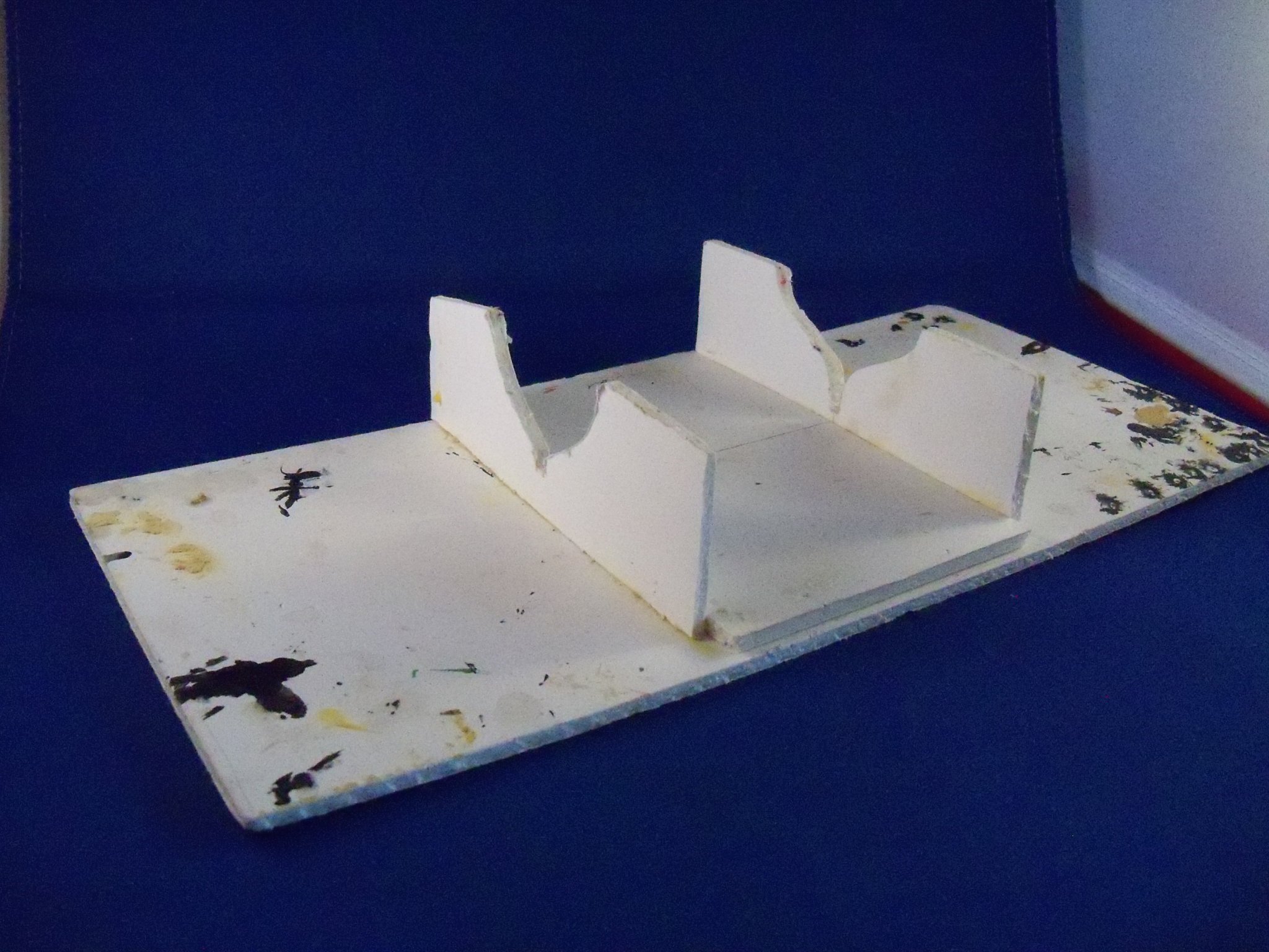
Since this kit was a solid wood hull model, I started by making templates for the hull and keels. I selected the templates at stations four and seven and constructed this simple cradle shown below that was made with some 1/8” foam core poster board to support the ship during construction.

Early on I decided to build up the bulwarks by adding the stanchions with planking applied to them, rather than carving them out, so these were removed right away. Once they were removed, I proceeded to slowly carve and sand the hull into shape using the templates to guide me. When I was finally satisfied, I cut, shaped and fit the keel, stem and sternpost until they fit properly and attached them with wood glue and nails.
As far as the deck of the ship goes, Model Shipways changed what I considered to be a prominent feature of the ship by not recessing the sunken cockpit and just substituting some metal coamings and leaving the deck flush. One could easily see that the ships wheel would not have any clearance with the deck, especially since the deck grating provided with the kit was so thick. So I decided to throw out the metal cockpit coamings and rout the floor down another foot to scale as was mentioned by Chuck in his practicum.
To do this I traced the outline on the plans of the inside face of the cockpit walls and added 1/32” outside of that outline. This new outline was located on the deck and transferred to the surface. Using my Dremel drill with the routing accessory set at 1/8” depth, the recess was cleaned out to that line.
Now that that was done the next thing I did was to discard the scribed decking sheets! For one thing, the decking layouts shown on the plans could never be done with a sheet. The stern decking was supposed to follow the curve of the hull and the decking on the foredeck needed to be nibbed into the shear strake. For another thing, even on a deck with all the planks running parallel to each other, the grain of the wood would make it all too obvious that it was not made up of individual planks. After all, we are for the most part trying to make it look realistic! So I cut enough 1/32” x 3/32” strips of my stock of basswood in 20 foot to scale lengths to use for all of the decking.
I started on the fore deck. The first step was to mark the location of the deck beams below and a centerline on the hull. The outline of the coaming for the companionway was also marked. The shear strakes were then steam bent to follow the edge of the hull. These were tacked into place temporarily. I marked the location of all the stanchions on the strake and cut a notch for every third one. Those notches were extended into the hull below about 3/8”.
Then the individual planks were set in place, starting with the two on each side of the centerline after first rubbing a #2 lead pencil along the ends and edges to represent the caulked joints. All of the planks were glued down with carpenters glue in a three butt shift pattern.
I continued installing the decking, alternating from one side to the other, cutting notches in the strake and tapering the ends of the decking where nibbing was needed. Rather than having the end grain exposed on the face of the step in the decks, I shaved the face back 1/32” and installed the decking up to the new face. The decking was omitted over the marked location of the companionway.
A 1/32” thick strip of basswood was steam bent and installed to cover that end grain that was shaved back earlier. It was installed overlapping the decking on the fore deck and trimmed off at the top of the step.
Moving on to the aft deck, the centerline and locations of the beams below were drawn on the hull along with the outlines of the coaming for the skylight, companionway and wheelhouse. I steam bent the shear planks on the sides and cut a piece to fit across the stern. Once again these strakes were marked, notched for the stanchions, and temporarily tacked in place. Next, I glued down a 1/32” x 1/16” strip of basswood with a slight overlap of the step facing for the edge plank. Once the glue was allowed to set, the planking here was laid similarly to the fore deck.
However, the deck pattern here required the planks to be steam bent and laid down parallel to the shear strakes. Alternating from one side to the other, the decking was laid toward the center until they met in the middle in a herringbone pattern at the stern. At this time decking was also laid on the floor of the cockpit.
Before finishing the decking, all of the tacked down shear strakes were temporarily removed. Using the ends of the beam lines previously marked and now revealed, a flexible straight edge was lined up and using a sharp HB pencil lead, I lightly poked a slight depression in the decking and twisted the point around a bit to make a representation of the treenails. The decks were then scraped smooth and given a coat of Minwax light oak finish that I let set briefly and then the excess was wiped off with a soft cloth. The decks were sanded with #400 wet/dry sandpaper and given two coats of matt finish polyurethane that was lightly sanded smooth. The caulking and treenail impressions left showing, provided a nice bit of detail even though it’s a little out of scale. It looked good to me, so I was happy with it anyway.
To leave me more room to work, I decided to skip doing the bulwarks until the deck houses and some of the fittings were finished.
Trying my hand at making the deck furniture from solid blocks as called for in the kit, I was not at all happy with the results. Thinking that I could certainly do a better job than that, these were quickly trashed. Seeing that the cockpit had already been carved out, I decided that I could also leave the companionway hatches open and make the interior of the skylight visible. Of course this meant that now I would also have to carve out the spaces below them. If I was going to do this, now was the time to do it. So…… once again I broke out the router and chisels and went to work.
Once these areas were carved out, I also thought that putting decking on the floors would be a good touch. Although it wouldn’t be all that visible once the deck houses were put in place, I installed it anyway. I also lined the interior walls with some grooved 1/64” plywood. Same reason I guess.
Moving on now to the coamings, I selected some 1/8” square basswood strips from my stock. I cut the pieces to size, cutting half lap joints for the corners. I assembled them with wood glue and set them aside to dry. After the glue set up, I filed a slight bevel on the outside edges. The coaming for the rear companionway was quite troubling at first until I realized that it terminated on the main deck where it ran into the cockpit walls. There were no coamings around the cockpit walls at the main deck or the walls inside the cockpit.
At this time it was time to decide what kind of color scheme I would use. Since this was to be my version of the ship, I planned to deviate somewhat from what the kit suggested. I would introduce a bit more contrast, by making the coamings and the shear strakes a light green color, rather than the light buff deck house that would be used on the remaining deck house walls and the inside of the bulwarks. The roof, hatches, cockpit walls, and the cap rails would all be stained with Minwax light oak and then two coats of matt finish polyurethane.
So now all of the shear strakes were given a couple coats of the light green (from my last remaining bottle from Floquil) on the areas that would be visible and they were finally glued in place. The coamings were also painted with the light green paint where they would be visible and then set aside until needed.
Returning now to the cockpit, the first step was to cut a strip of wax paper followed with a strip of paper coffee filter and line the cockpit walls with them. I ripped some very narrow strips of 1/32” basswood to use for the vertical panels. I cut several pieces of them long enough to reach from the decking on the cockpit floor to the bottom of a cap rail 1/8” above the upper deck. These were then glued to the paper filter lining on the walls for the inside panels and left there to dry thoroughly.
Once dry, I cut several more pieces for the outside panels long enough to reach from the upper deck to the top of the inside wall panels already in place. These pieces were then glued to the outer face of the inside wall panels with their joints offset from the joints on the layer below.
Confused? Well, this actually left me with a cockpit wall above the upper deck 1/16” thick and 1/32” thick below the upper deck. The top of this double thickness wall was sanded even for the application of the wall cap. With the coffee filter paper glued between the layers to hold it together and the wax paper preventing the assembly from sticking to the wall of the pit, it could be slipped out of the pit in one piece. This allowed me to trace the outline on a piece of stiff card to make a template for making the cap rail. I took the resulting outline as the finish outside edge of this cap and drew the inside edge to the required finish width of the cap. I made the cap in five pieces and even made scarf joints with two quarter knee pieces at the corners so no end grain would be exposed. (They were only about 1/16” long!)
I sliced a 1/32” strip of maple from a piece of ¾” maple and sanded it down to 1/64” thickness for making the cap rail. Once it was glued down to the template with rubber cement and with carpenters glue at the joints, I set it aside for a few days to be sure it was held together good.
Very carefully it was separated from the template and glued to the top of the cockpit wall while it was set in the recess. Wow, wasn’t that easy? This whole assembly was then removed to be stained and sealed. Oh wait, the ends of the wall assembly would still need trimming to join into the sidewalls of the rear companionway. I can hardly wait! Showing it to the Admiral, she thought I was nuts!!! Here is a photo of the cockpit walls with the cap rail already applied.
-
Since the Pandemic was declared on Friday (The 13th go figure.) it looked like I would have quite a bit of time available to actually write up a log for this ship that I started way back in 2013. At that time I was still getting my feet wet so to speak with computers. Writing a log, coordinating it with pictures and sending it through the computer was way out of my comfort zone back then.
But since I started with my hybrid model of the 1:87 whaler Wanderer by Aurora and am doing a log for that during construction, I thought I’d do sort of a retroactive log of the construction of my Phantom. Since I am quite a ways into the build already, most of it is from memory and my notes. Eventually the log will catch up with the build, but as I am building both ships at the same time, it will undoubtedly take quite a while. Also, the photos were taken recently rather than during actual construction, so they will be mostly out of sync with the log. So without further ado here goes nothing.
- GrandpaPhil and Y.T.
-
 2
2
-
-
Man, now that's what I call going to the extreme to detail the model! WOW!!!
-
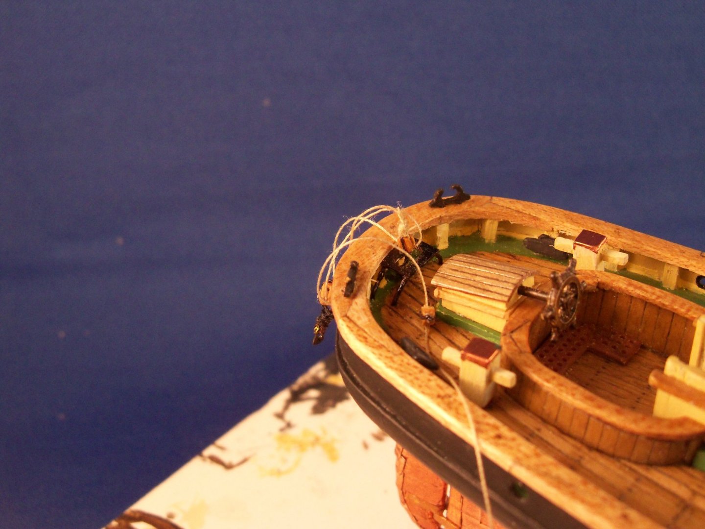
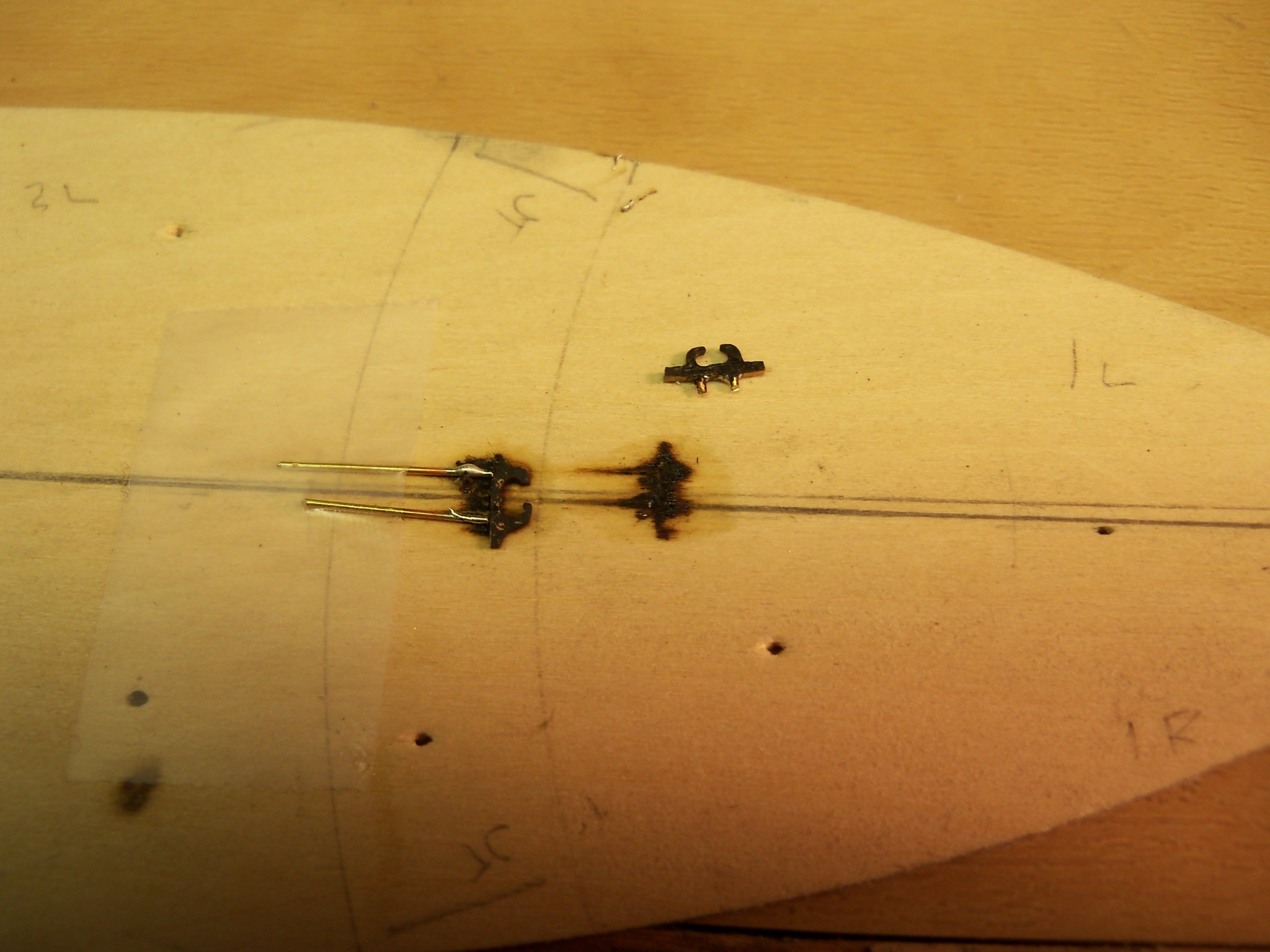
Well since the Pandemic arrived, I had some spare time to model the fairleads. I took a 1/2" wide strip of 1/32" thick brass to my machinist vice with a paper pattern of the desired shape glued to the face. Using a jewelers saw and my skinniest files, I cut the shape out. It took quite some time before the shape was acceptable, sawed them loose from the strip and coated them with Brass Black.
With the fitting being a mere 1/32" thick I didn't think glue alone would be able to anchor it to the rail. So two pieces of 1/32" brass wire were taped down to the face of my basswood deck pattern along with the fitting to keep them still while I soldered them together with a soldering iron. Then when done the wire was cut to length as shown in the upper right of the photo below.
Once the fairleads were cleaned up with my files they were given another bath in the Brass Black and set aside to dry. I located the desired position of the fittings by using the wire pins to put impressions in the cap rail to locate the holes. A pin vice was used to very carefully drill holes for the pins. Using a touch of medium CA on the ends of the pins they were pressed in place to let the glue fully set.
So below is a photo of the fittings in place.
I wasn't totally satisfied with the fittings, but as my dad always used to say: it's good enough for government work.
- tkay11, John Allen, Duanelaker and 10 others
-
13
-
-
While reviewing your log, I noticed a detail shown in these two photos in the bulwark between two stanchions that is unfamiliar to me.
.jpg.d3b4eff88b972c30957ff4bd5177b379.jpg)
It appears to be a horizontal piece of blocking with an oval shaped hole. Is this a reinforcement of some kind for a mooring hole in the bulwark , and if so, would it have a metal lip similar to a hawse hole?
I am building the MS Phantom that shows a pair of similar holes in the bulwarks near the bow and stern opposite a pair of bollards. My plans don't show a detail of it at all, so I am just assuming that this is the case in ships with open bulwarks. I can't remember seeing a photo or drawing of this detail anywhere else either.
- popeye the sailor, gieb8688, Fright and 2 others
-
5
-
-
-
There were several articles submitted to Ships In Scale magazine by Antonio over the years which I thought were of great interest to me. So, when the book came out in 2005 and was offered for sale through SIS, I jumped at the chance to get a copy. I immediately put it at the top of my X-mas list and the admiral got it for me. At that time, I think it sold for about $35, so if you can get it for less than $10 you will have yourself a real bargain! He had a very extensive model shop with many innovative ideas and pieces of equipment
Since getting the book, I have used many of his ideas to make versions of them for myself. Most recently I modified a broken drafting chair into a mobile support table for my model shop. Both Antonio and I strongly believed in modifying old equipment for other uses rather than to just discard them.
Unfortunately, he has recently passed, so the book will be his last. Although I never met him, I somehow feel that I have lost a kindred spirit.
- Bob Cleek, thibaultron and mtaylor
-
3
-
I also use the product I find that it's easy to use. You simply soak the parts until you get the desired finish, set on paper towel to soak up the excess, and let thoroughly dry over night. Unlike paint, it adds very little thickness to the parts. That's something quite important with very small parts!
- thibaultron and mtaylor
-
2
-
-
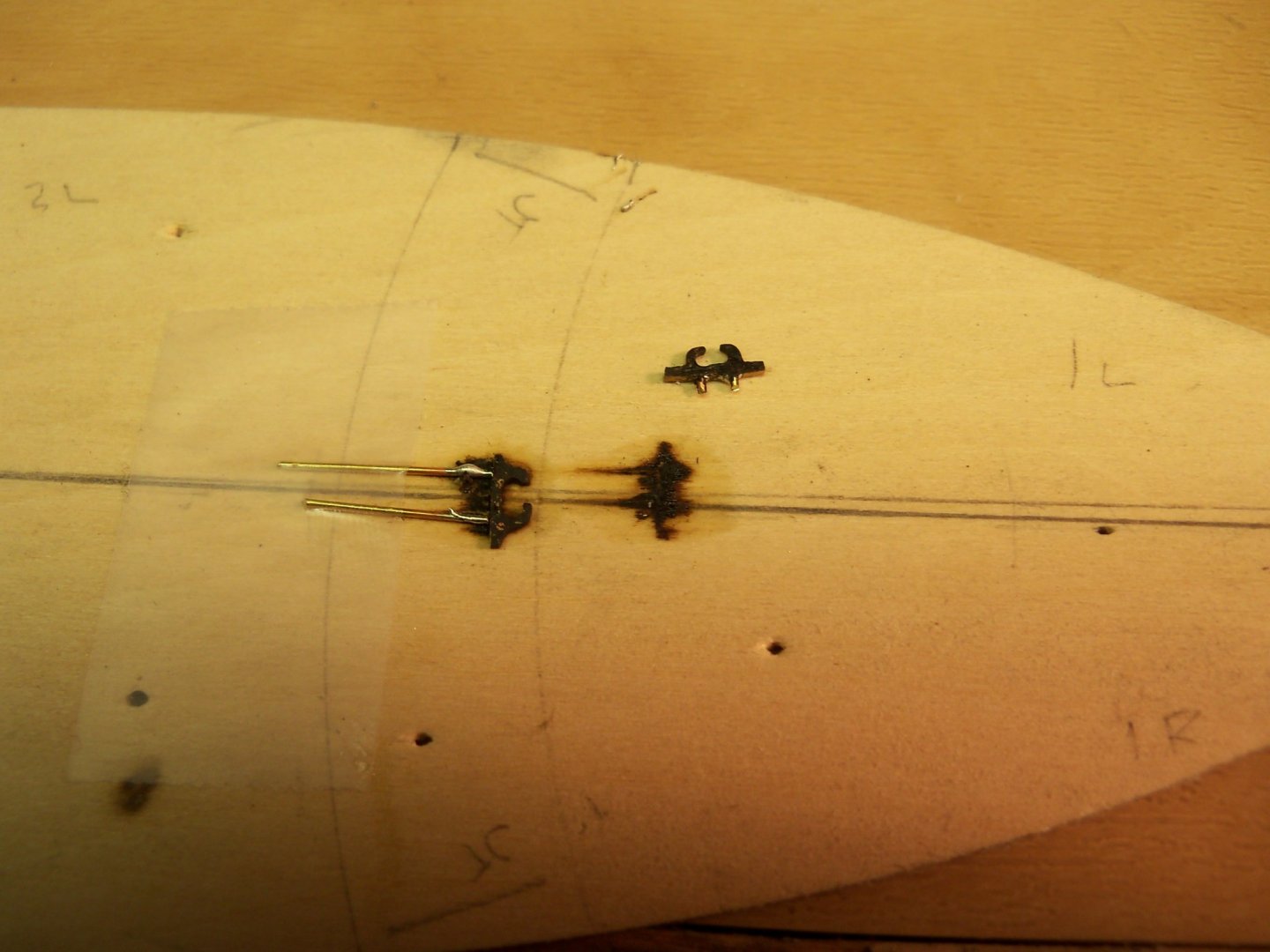
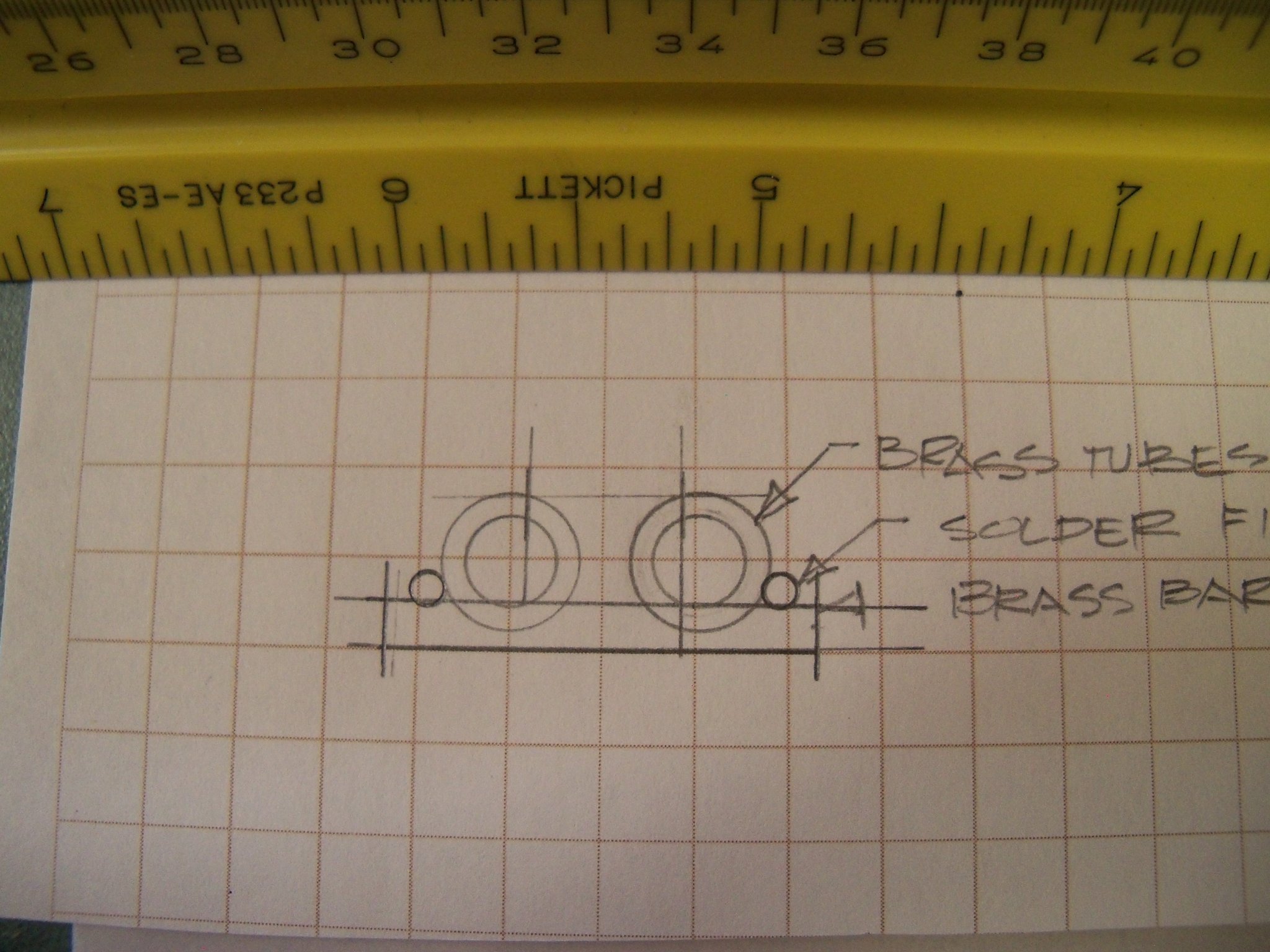
I am trying to make a matching pair of fairleads for the stern cap rail of my 1:96 MS Phantom as shown in the actual size sketch below. (I drew it at ¼ actual size and reduced it down to the scaled size needed.)
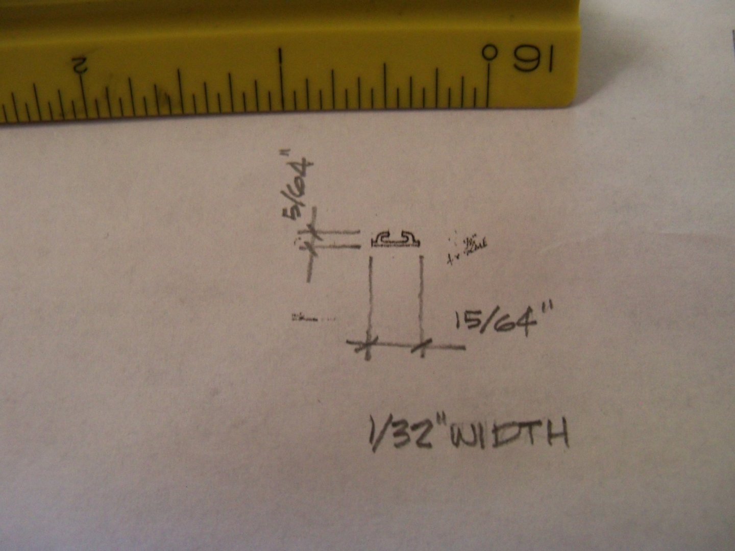
My first idea was to print the scaled drawing on paper as a pattern and apply it to a 1/32” thick piece of aluminum bar stock and cut and shape it with drills and files, but the needle files that I have, aren’t nearly thin enough to get inside the hooked ends to file them down. So my next attempt was to make them according to my notes shown below here.
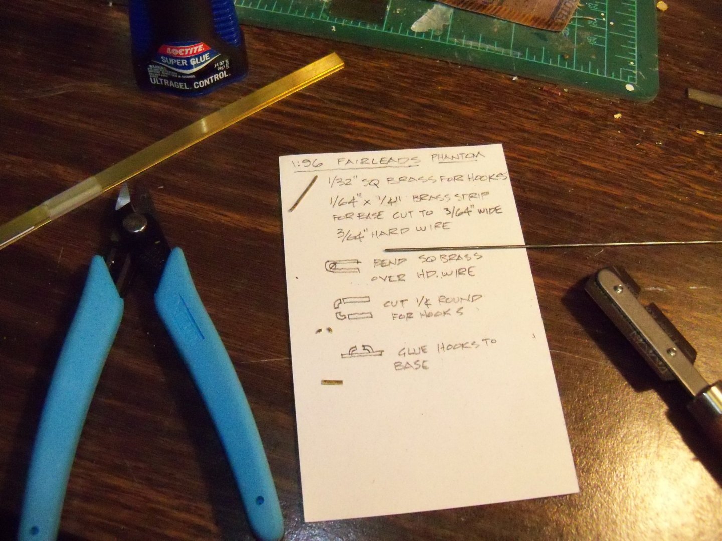
The hooks were made from some 1/32” square brass stock that was bent over a piece of 3/64” hard wire and being cut off as shown. The base was cut from a piece of 1/64” thick strip brass. I tried joining the pieces with AC but to no avail since the assembly was just too weak to take any stress applied by trying to file it to shape. Silver soldering seemed to be my only other choice available.
However, clamping such veeeeeery small pieces in place for soldering can be just about impossible since regular clamps would be much too large. When using a torch the flames air flow causes the tiny pieces to shift around. Touching a soldering iron to the pieces will do the same. I considered making a jig to hold them by carving a recess into a piece of wood for a tight fit, but I would have to make one for each of them since getting the solder to melt will just burn the original jig. I’m not aware of any other material that could be formed to make such a jig that also wouldn’t just melt or burn.
Another method that just occurred to me would be to flatten the bottom edge of some hollow brass tubing and solder them onto a piece of brass bar strip using the solder as a fillet. Then I could make the vertical cuts to open the gap at the top of the fairlead. But, once again that still leaves the problem of holding those tiny pieces together while soldering.
Any suggestions on keeping everything still while soldering them together?

-
13 hours ago, CDW said:
Those blades turn so fast with so much mass, they can cut you open like a buzz saw.
Don't forget the decapitation of Combat series actor Vic Morrow during filming from a real helicopter!
- Canute, popeye the sailor and mtaylor
-
3
-
12 hours ago, lmagna said:
I would LOVE to have one more ride.
Sorry Lou, but leave me out! My one flight was more than enough for me! (I wonder how much those tourists in the video would have enjoyed their flight blindfolded.) 😖
- lmagna, popeye the sailor, Canute and 2 others
-
5
-
As per Murphy's Law, after being unable to locate my jig saw blades when I needed them (way back on post #2) for this project, I found them today while looking for something else.

- kurtvd19, Duanelaker and thibaultron
-
3
-
-
Well Justin, first off I would suggest looking at the topic So Where Do You Do Yours Then (Model Making That Is) There are close to 30 pages of suggestions there that would be of help. I myself, have put my two cents in it on page 26.
Personally, the thing I have found to be the most helpful to me has been mounting just about all of my equipment on rolling tables or benches. It can allow you to have more space to work in by rolling the equipment that is not needed at the moment out of your way. My entire shop used to share room with our cars where all I needed to do to work was to back the cars out, leaving plenty of space to move the equipment from the perimeter for working space.
Once I became confined to a wheelchair, most of my shop moved to the basement, but I still find that having the tools mobile makes my work easier. (Not to mention much warmer in our WI winters.)
- Jorge Diaz O, druxey, Bob Cleek and 4 others
-
7
-
On 1/14/2020 at 1:14 PM, lmagna said:
Hopefully at least some of this will key good, funny, or memorable experiences from people that happened in their lives 50 years ago and helped form who they are today and they take the time to share it here whether it is in story, model, or picture form.
Here is my not so good (or funny) trip on an Army Helicopter.
Sometime in the spring of 71, while on temporary duty at the Ft. Sill Army Hospital, I had my first and only experience with an Army chopper. In a joint Army/civilian disaster exercise, I was volunteered (?) to participate as a victim in a major highway accident. My part was to pose as a victim with severe head trauma which required me to wear a neck brace and to have my head, including my eyes, to be heavily bandaged. I couldn’t see a thing after that and was strapped down onto a gurney which was hustled off to a waiting chopper and set inside with the doors still wide open.
Well, the pilot seemed to think that trying some drastic evasive maneuvers was needed for some unknown reason or other. All I could think of the whole trip to the hospital was that I prayed that the gurney had been solidly anchored in place as I desperately gripped the sides of the gurney hoping not to be ejected from the cabin as the wind howled by me and he made some pretty wild twists and turns.
I may have yelled out some choice oaths at the pilot, but with the racket from the choppers engines he probably couldn’t hear me at all. (That was probably for the best anyway since I’m quite sure he outranked me by quite a bit.) It was like riding a monster roller coaster with your eyes closed and you couldn’t remember if your seat belt was hooked up. Luckily, I had not eaten much that morning or I’m sure I would have left quite a mess to clean up.
I have never been that close to a helicopter since!!!!!
- Roger Pellett, Canute, mtaylor and 4 others
-
7
-
-
I came across an add on U-Tube for an adhesive often used by a dentists, one of whom thought of expanding its use on many more applications. It bonds a vast list of materials including wood, metal, and glass by basically, welding the materials together. It remains in liquid form until exposed to a small UV light tool for four seconds. This adhesive dries clear and once hardened, it can be filed or sanded to shape. The video has a demonstration of its strength in the video where a broken wire cable was glued and able to support the weight of a full grown man. It goes under the brand name of Bondic. A web site address of getbondic.io was listed on the AD. It sounds like something with many applications in our hobby. Has anyone here know of or ever used the product before?
- BANYAN and thibaultron
-
2
-
4 hours ago, DonInAZ said:
Was surprised not to see the Model Shipways Phantom on the list of beginners kits as it is so heavily promoted (or at least it used to be) as a good model to start with.
I would second that recommendation, especially with the availability of the practicum here at MSW by Chuck to follow. They are a vast improvement over the kits instructions and there are several logs to review on it's construction on our site.
-
You can go to the Quick-Find Indexes to BUILD LOGS FOR KITS in the wooden kits section and scroll down to La Nina by Igorsr Amati/Victory. There you can follow his build of your kit. According to his log the hull is planked first. Then the bulwark extensions are cut off before the false deck is installed. So cutting notches for the extensions is not necessary.
- Larry Cowden and ccoyle
-
2
-
Another problem has come up concerning mounting the ship on the base. As the keel on this model is just 9/64” wide, I discovered during my search for a source for mounting hardware that while getting 2 bolts in 7/64” diameter in anywhere near the 3 ½” lengths that I will be needing is possible, it would also be extremely expensive! (Like $45 each expensive.) I also thought about using some threaded rod, but there again the cost would be prohibitive.
I found that the smallest diameter that is readily available and at the same time still affordable would be 1/8”. So, the problem now becomes how to conceal a bolt that will clearly show as it passes through the 9/64” keel and into the keel supports.
It appears that my only solution will be to have some timber blocks on both sides of the keel where the bolts pass thru. While I haven’t been able to find any more info anywhere in any of my references on blocking the sides of the keel, I shall incorporate two pair of them on mine regardless. (Although there is an indistinct indication on the AD photo of some kind of blocking between the keel blocks just below the mainmast and the stern of the lowered whaleboat, it isn’t at all clear exactly what that is.)
Each pair of side blocks will span two keel supports and although the exposed portion of the bolts will be minimal, they will be painted black. I made a sketch below to show the location of the blocks and the drilled holes.
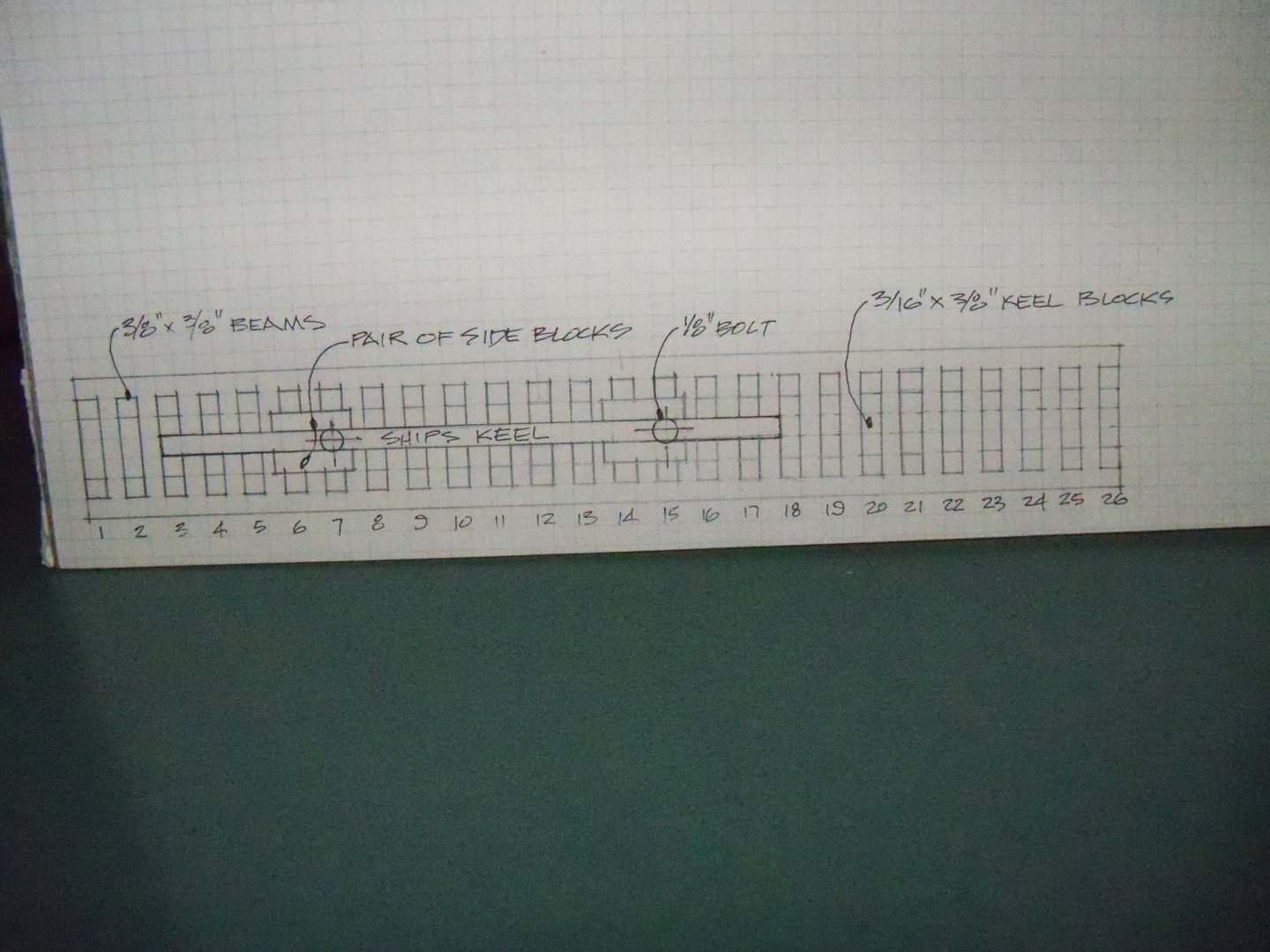
I had also contemplated threading the ends of a solid metal rod for some nuts, but as I don’t possess a tap and die set for this I didn’t see that the added expense would have been worth it. At any rate, the 1/8” bolt should provide a more secure mounting of the model than one of a mere 7/64” diameter, so maybe it’s for the best anyways.


Phantom 1868 by BETAQDAVE - Model Shipways - Scale 1:96 - N.Y. pilot boat - Highly modified hull, deck furniture and fittings
in - Kit build logs for subjects built from 1851 - 1900
Posted · Edited by BETAQDAVE
typo
So, for something a little less nerve racking now, I moved on to the building the skylight. All of the deck structures were built with basswood and separate from their coamings to protect them while working on the rest of the model. I drew up three versions of its construction before choosing the one closest to the layout shown on the plans. The walls were built first using 1/32” x 1/16” as a bottom plate arranged in a simple jig set up to hold it together as a flat rectangle with butt joints in the corners while glue up with carpenters glue. When the glue set up it was removed from the jig and reloaded with more of the 1/32” x 1/16” material, but I made the butt joints offset from the arrangement of the bottom plate. This was then glued and dried.
Using a small square, I laid out the arrangement of the vertical posts and glass bars on the plates making three openings on the sides and two on the ends. Each opening had two bars apiece. The posts were made of 3/32” lengths of 1/32” x 1/16” glued between the top and bottom plates. But, before I assembled the walls, the plates were stacked on top of each other and taped together. Using a #68 bit the holes for the glass bars were drilled thru the top plate and not quite thru the bottom with my Dremel drill press to assure alignment of the holes. Now the plates were glued up with the posts glued in between and the assembly was painted light buff deckhouse. Once dry, I inserted short lengths of some hard black wire for the glass bars through the holes and applied an additional plate on top of the end walls shaped with the camber for the roof that was also painted. I drilled for and installed four small brass locating pins into the bottom of the assembly for later attachment to the coaming. For the glass, I took some clear plastic from a packaging shell and cut it for a force fit inside the skylight frame so that I wouldn’t have to use glue that might obscure the plastic.
To make the roof of the skylight I cut some very narrow strips of 1/32” basswood which I put over a cambered waxed form covered with coffee filter paper. I used some wood glue on the paper and assembled the strips edge to edge and let dry. The filter paper was very thin but when glued to the planks the assembly held together quite well. (Although the filter paper got quite wet with the glue, it didn’t wrinkle up at all.) This assembly was then trimmed with end caps that were fit and glued on. I finished these roof planks the same as I treated the deck planks and when it was glued onto the walls it had a much more realistic look to it than my first attempts which had been cut from a sheet and scribed. Here are some pics of the finished skylight below.
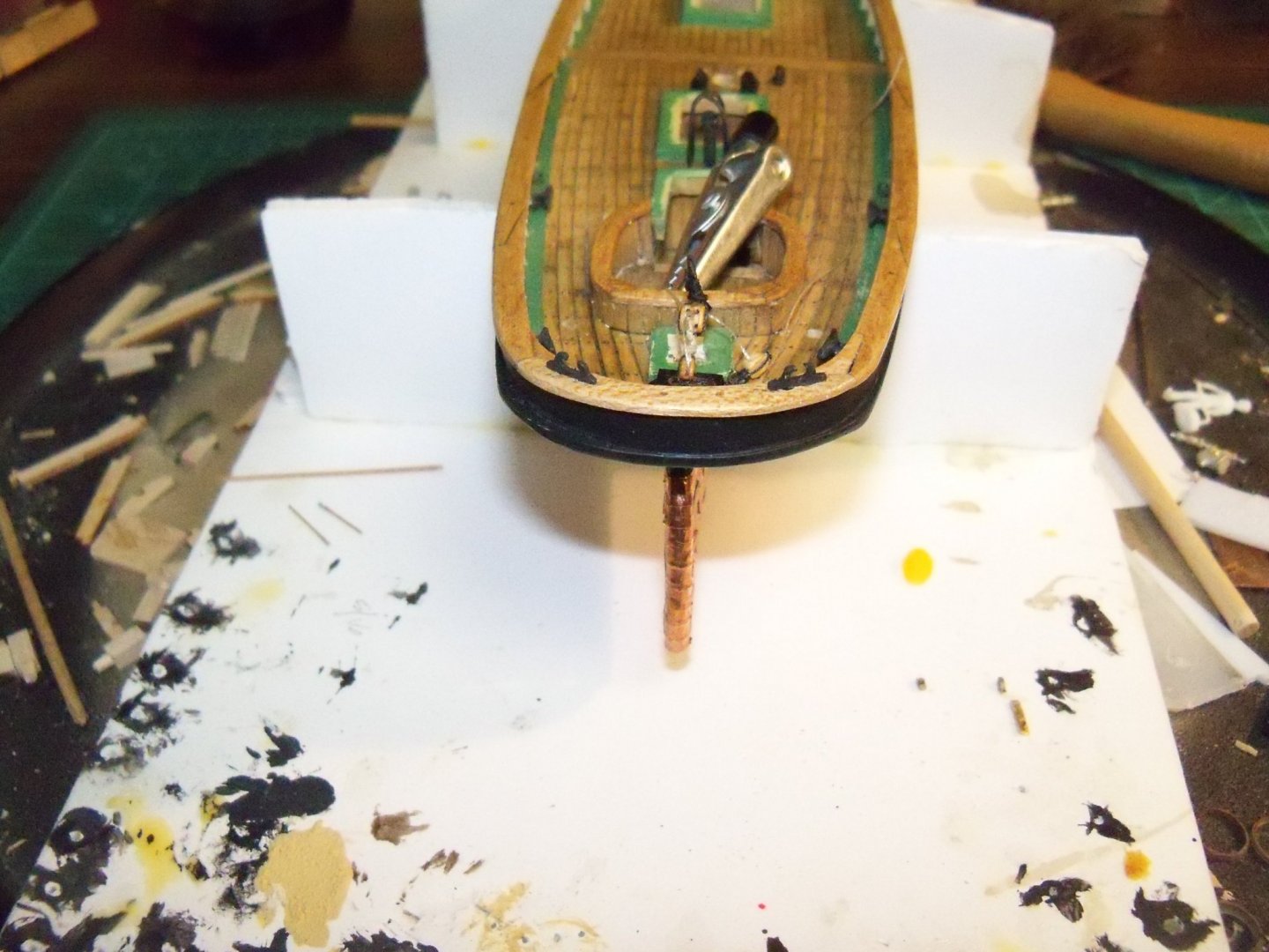
For the wheelhouse, I cut off the end of a piece of basswood that was formed to match the required W and L dimensions so that no end grain would be visible. One end was then tapered and filed down to form the roofs sloping cambered top. A piece of 1/64” square basswood was cut and fit for the trim piece. The face of the wheelhouse was drilled for the ships wheel shaft. The assembly was then painted light buff deck house.
Since the roof on the wheelhouse was much thinner than the other deckhouses, I used some of my grooved 1/64” plywood instead. Since the grooves were too far apart, I scribed lines in between them. The roof was stained and finished like the decking on the top and the perimeter of the bottom. Once dry, it was glued on by clamping it with a cushioned pad on the roof side to ensure it would follow the shape. The edges of the roof were then finished; the wheel was painted a dark brown and glued on with medium CA. Below are a couple of photos of the completed wheelhouse.