


allanyed
-
Posts
8,149 -
Joined
-
Last visited
Content Type
Profiles
Forums
Gallery
Events
Everything posted by allanyed
-
 Amy, Please post some photos and any information you might have on the particular ship. That might help get some responses for you. Allan
 -
Making Shackles my way…
allanyed replied to Thanasis's topic in Metal Work, Soldering and Metal Fittings
Thanks for taking the time to make this presentation. It never ceases to amaze me how many talented members with ingenious ideas that we have here at MSW. Allan -
cleats, ring bolts and belaying knots
allanyed replied to jray47's topic in Masting, rigging and sails
Ray or is it J? Page 161 of Lees Masting and Rigging has a drawing showing how to secure a line to a ring using a fisherman's bend. Allan -
Gregor What was the real world overall length of the Jacinthe when rigged? Thanks Allan
- 121 replies
-
- 1
-

-
- la jacinthe
- schooner
- (and 2 more)
-
Robboxxs You are right, the compound that was used and called brass in Lavery's Arming and Fitting was, as he states, more akin to bronze with 85 to 90 percent copper with portions of tin, zinc and other metals. Bronze is typically made with 12 percent tin and some other metals including zinc. Brass is an alloy which is primarily copper and zinc rather than tin as the main secondary metal. Allan
-
Pandora by marsalv - FINISHED - 1:52
allanyed replied to marsalv's topic in - Build logs for subjects built 1751 - 1800
Marsala I hope you don't mind a bunch of questions so here goes. Did you etch away material around the monogram so the monogram itself is raised? Any details you can share on how you made these would be very much appreciated. Were there any problems with the CA holding tight during or since the blackening process? What blackening solution do you use? Sorry for all the questions, but your cannons are extremely fine and I for one would love to know more. Thanks Allan -
Don I am not sure about Spain, but the English were converting to iron, at least on large vessels, before 1650. Cost of iron was 1/4 the cost of brass, or less, and the Royal House was in fact cost conscious so liked the idea. After all, it was the Kings Navy. Lavery gives a good history of and reasoning for and against the conversion in his Arming and Fitting book. Allan
-
SOS I have visited Pearl harbor and the Missouri, several subs such as the Ling, the USS New Jersey, USS Texas, the Intrepid and a few others. While I enjoyed the visits and can see a museum ship or two, they are a huge waste of money IMHO. I agree that truly historic vessels would be great to keep and see such as the Wasa, Victory, USS Missouri and a few others but how many is too many? Jud, As far as mothballing and being available to re-activate, they are out of date well before they are set aside and could never be brought up to modern design and armament standards at a reasonable cost. The new vessels are stealthy so the old designs would never be able to meet that criteria. Better to re-use their steel and build from scratch with the latest technology than try to make a silk purse from a sow's ear. I served and am very happy to have done so, but it was the people, not the steel that I remember most of all. I would enjoy having a few beers with old shipmates far more than taking a tour on those ships Just one man's opinion. Allan
-
Ronald, I am anxious to see the end results. From looking at how you laid out the paper, the strips do not appear to look anything like the actual planking should, especially at the bow. I hope it turns out to be a neat new way, so again, I am anxious to see the end results. Allan
-
WOW, That is one heck of a project Wayne. I cannot see anyone that would not use it. Allan
-
Keith, What nation? The earliest date I see in Goodwin's Construction and Fitting of British Ships of War is 1664. Laughton's book Old Ship Figure Heads and Sterns mentions the Dutch having Catheads closer to 1630 and those were more on the head itself rather at the corners of the head. Allan
-
Pat, Are you using ribs between the trucks and did you put lash lines on the ends of the parrel ropes to make the final tie off? Page 126-7 of TFFM Volume IV gives a good description and comments that it is an exacting task so you are not alone in finding it anything but simple or easy. Allan
-
Keith, Hope you don't mind this question, but what are the ribband looking strakes? I have seen ribbands and harpins used to hold the frames secure until planking is put on but never seen anything like this over planking before. Thanks Allan
-
Ed, The anchors are beautifully done! And as far a clutter, I think you added some just for the photo. When I was lucky enough to visit you and your shop many moons ago, there was not even a spec of dust thanks to your central vacuum set up and duct work going to each work station. Heck, even the wood scraps were neatly separated and neatly stored if I remember correctly. Then again the remembering part is always an issue. As Bette Davis put it so well, old age ain't no place for sissies. As always, thanks for sharing so much on your building log. Allan
- 3,618 replies
-
- 6
-
-
- young america
- clipper
- (and 1 more)
-
Druxey, You have proven that one need not build a 36, 74, or ship of the line to wind up with an impressive piece of art. Sometimes smaller is better in that it is indeed possible to wind up with a beautiful model in months versus years. Allan
- 641 replies
-
- 9
-
-
- greenwich hospital
- barge
- (and 1 more)
-
Gary, So far so very good! Did you completely fair the erected frames or is there still some wood to work with when fairing the completed framed hull? Thanks Allan
-
Using a server with dead eyes, standing rigging
allanyed replied to achuck49's topic in Masting, rigging and sails
Chuck, You did not mention this, so my apologies for bringing this up if you already were aware. For square rigged British ships, at least, only the forward most shroud of the foremast and mainmast shrouds are served their entire length which is to protect from chafing by the lower courses. The other shrouds are only served where they pass around the mast and also whipped on the ends. Allan -
Big Congrats Druxey. This is far from what I have had the good fortune to see of your work over the years, yet every bit as beautiful and it has been a joy to follow your build log on the entire process. Can't wait for the next one!!! Allan
- 641 replies
-
- 6
-
-
- greenwich hospital
- barge
- (and 1 more)
-
Alan, What is the applicator you show in the photos? Are you using to apply glue? I have only seen these as combination mascara/eyeliner applicators in my business life and never thought of them as useful for anything else. Clever way to carry some volume yet apply in "pinpoint" areas. Allan
-
CindyP I know this will add to your shopping list, and I agree with the above lists, especially a good xacto handle and blades jewelers files and rotary tool I would add good chisels as a first or second step. If you start using them early on you will find them to be invaluable for kit or scratch building, POB, or POF. I have no idea what brands are available in South Africa, but Hirsch, Veritas and Sorby are three brands that are quite good, and there are any more. You do not need many. I use 3, 6, 12, and 25 mm for almost all l my chisel needs. A good sharpening stone and jig will keep you in razor sharp cutting mode for years to come. As with anything else, you get what you pay for. Allan
-
Barbara On page 332 of Chapelle's, American Fishing Schooners 1825 to 1935, the flying backstay hauling part, when not in use, was made fast around the a r se of a block that appears to be fixed to the hull in a sketch he provides. He shows it just aft of the main mast channel on the starboard side. When in use it belayed on a cleat inside the monkey rail, port or starboard at the transom corners. There is no mention of hooks on the end of the hauling part of the line. The sketch is labeled as Belays of a typical fishing schooner 1905-1925 from Charles Sayle's notes. Allan
-
Stem Bolting Arrangement
allanyed replied to Matrim's topic in Building, Framing, Planking and plating a ships hull and deck
Further to Druxey's post, the Swan Class ships in David Antscherl's series date 1767 to 1780, closer to the 1788 Shipbuilder's Repository than the 1805 Steel Elements and Practice of Naval Architecture. There are many differences in the two sets of scantlings including the size and number of bolts in various locations on the various size vessels. Allan -
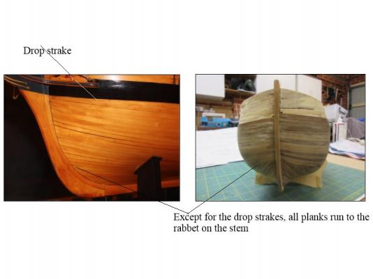
Hello Clogger You mentioned drop strakes and I have shown one on the following. Also note the difference in the planking on a model from the museum at Preble Hall and yours. The planks below the wales taper and all run to the rabbet on the stem rather than butting into the side of other planks. It is all a learning process. I am curious though to know if the kit plans showed any details on laying the planking. As mentioned earlier, there are great planking tutorials on this site that will help you as you gain experience. Keep at it, we are ALL learning something new everyday. Allan
-
Great work Druxey! How about having the oars in an extreme release position, that is to say, swept fully aft but not shipped. Just another positioning to try and see how it looks to you. Allan
- 641 replies
-
- 3
-
-
- greenwich hospital
- barge
- (and 1 more)
-
Merchen Last year you complained that there were very few responses to your post. Most members probably see your German post and tune out immediately as they do not want to take the time to start getting a translation, which you should be doing. Regardless, the work is remarkable and a joy to see. Can you post (in English please) more about the tools and methods that you use Seeing the finished work is great, but many of us are interested in learning how to do this and showing your tools and methods would be very welcome and much appreciated. Thank you for sharing Allan
