
.jpeg.882f0a147f14858c9e673da7e13d8ebe.jpeg)
RossR
-
Posts
438 -
Joined
-
Last visited
Content Type
Profiles
Forums
Gallery
Events
Posts posted by RossR
-
-
I like adding as much rigging detail, but worry my sails cover up much of it or detract from it. Love what you are doing?
How are you adding the leech lines, what is the sail end attached to?
similarly do you have the bunt lines just drop below the yard the back up through the block to the belay pin?
-
I will be starting my half hull in a few months, really appreciate the level of detail you are sharing, plus the tip on using card stock. Keep up the good work.
- Jim M, JacquesCousteau and robert952
-
 2
2
-
 1
1
-
-
I mentioned in a previous post that I expected my progress to slow due to busy work life for the next couple months, so no new pictures or progress. I did want to share a follow up to a post I made in a topic related to why we started building models. After the post I thought a little about how I look at the models differently now than I did when I started. I only wanted to build the kit on my first model. It didn't occur to me to consider accuracy of the kit or the level of detail the manufacturer chose to include. I discovered MSW as I was completing that model. Since then I have slowly started thinking more about those details. Particularly scale. I also had an opportunity to acquire a copy of Lees Masting and Rigging of English Ships of War and two of the Anatomy of the ship books, Victory and Constitution. To be honest I am struggling to get much out of Lees book. I feel like I need Masting and Rigging for Dummies first. Lees book is full of great information, but not written for a beginner.
Anyway, after the post the other day, I decided to use Lees to figure out what diameter the shrouds should be on my current build. I know Lees book deals with English ships and mine is model is Spanish, but it was more of an exercise in using the book to calculate the should diameter. I did make the assumption that the Mast on the model was an accurate scale representation of the actual diameter of the mast on the real ship.
In Lees the diameter of the various lines are calculate as ratios of other lines or ultimately the associated mast. My lower mast was 0.478 inches in diameter. According to Lees the main stay would have a circumference of 1/2 the diameter of the mast. That works out to a diameter of the main stay of 6.85 inches. .478 x 90 (scale of my model) equals 43 inches. Divide that by 2 and you get a circumference of 21.5 inches which equates to a diameter of 6.85. The lower shrouds are then calculated as 6.85 x 0.60 equals 4.11. That divided by my scale of 90 equals a shroud diameter of .0457.
As a check on reasonableness I pulled out the Victory Anatomy of the Ship book and checked the lower main shroud diameter of HMS Victory and that is listed as 11 inches in diameter which works out to 3.5 inches. Divided by 90 and I get 0.038. The Santisima Trinidad was slightly larger that the Victory so I would expect a slightly larger line. I may also be basing this on a mast that is not an accurate representation. Either way, I was excited to use Lees and not just have it take up space in my shipyard.
I was also excited that I had some 0.045 rope from Syren left over from my Diana, and I am going to use it on this current build.
Any way I want to thank everyone on the site that has helped me appreciate the details that can make a model even better that the kit. If you are only interest in building the kit, please know that that is just fine. I think that approach got me started on a hobby I really enjoy .
Thanks for reading and being patient with my lack of progress,
- DonSangria, Waitoa, JacquesCousteau and 2 others
-
5
-
Great work. Your rigging is so neat and clean. I hope to come close to what you are producing someday.
I like the detail of the wood bands above and below the woldings. This is a detail you don't see added too often, Sorry if you mentioned this in an earlier post, but did you use card stock for that?
-
No build log. I discover Model ship world just as I was finishing my Beagle.
-
I agree that not drawing the plank joints looks better. Nice work.
-
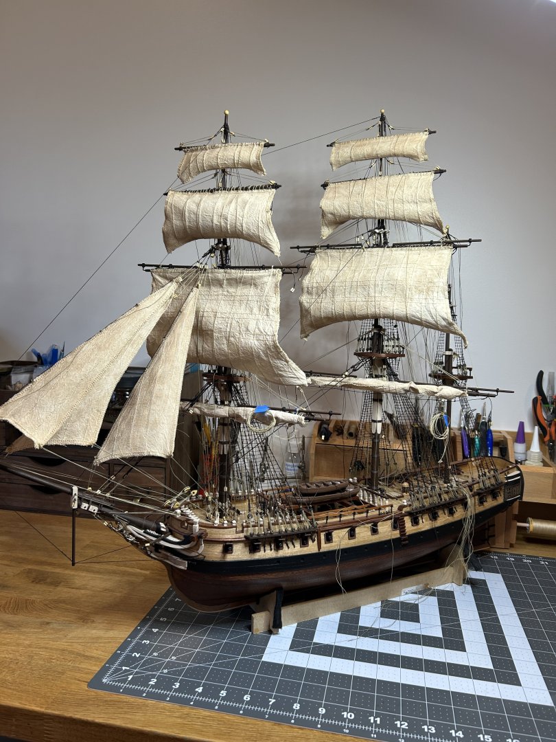
I have been making some slow progress on the ship, and I thought I would give a quick update. I have added the fore sail as a furled sail, and all the sails on the main mast with the main sail furled like the fore sail. I still need to add the braces and the sheets and tacks on the fore and main sail. After the stay sails are added I will complete those rigging elements.
Next up are the main and mizzen stay sails. Sorry I don’t have more pictures right now.
-
If you really want to start out with a three masted ship consider Occres HMS Beagle. There have been a few first build build logs that turned out really well of this kit. I didn’t do a build log, but it was my first kit and I was happy with the results.
if you want to learn skills to prepare you for something like the USS Constitution, some of the advice from others above might be the way to go.
-
-
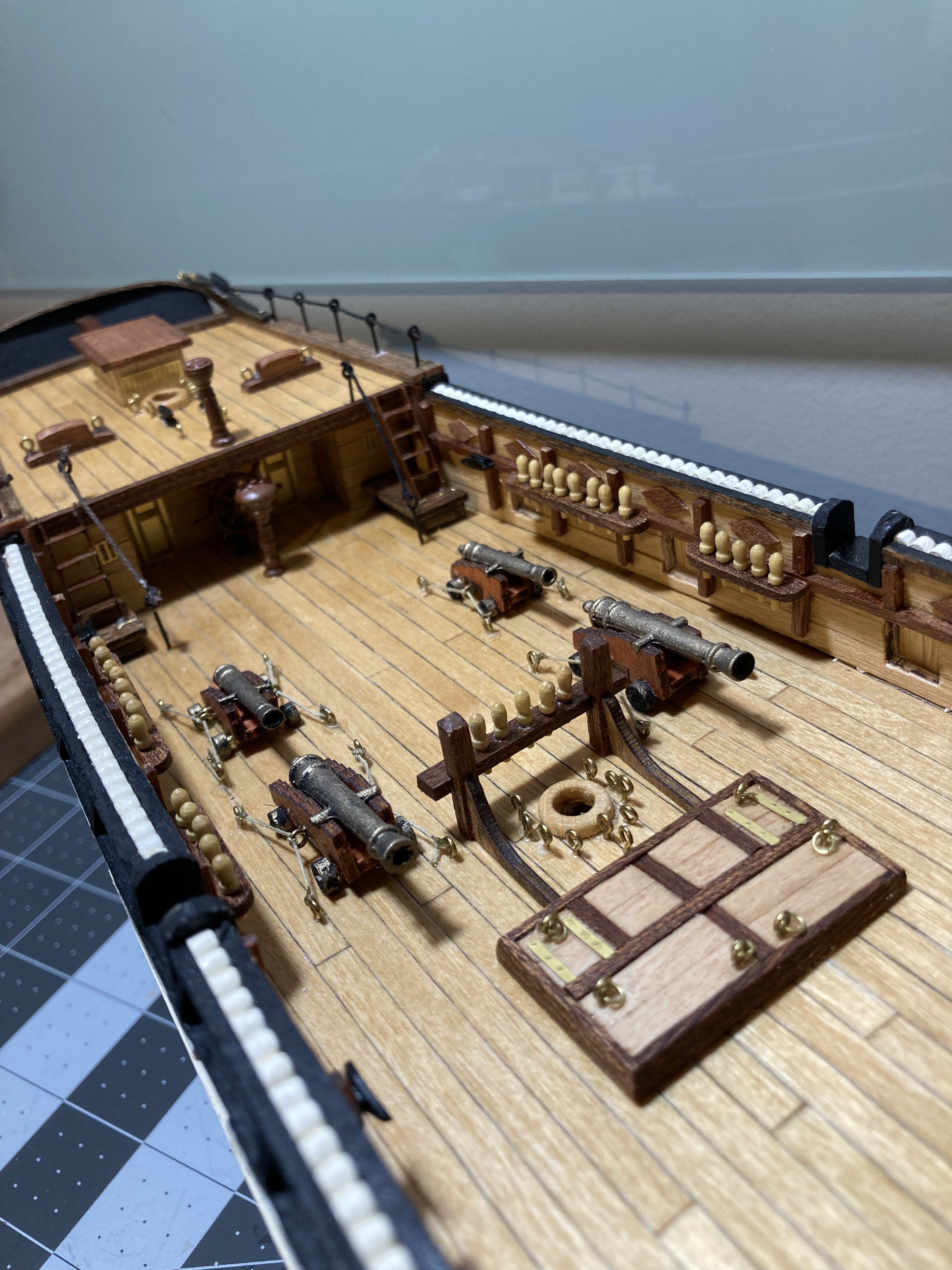
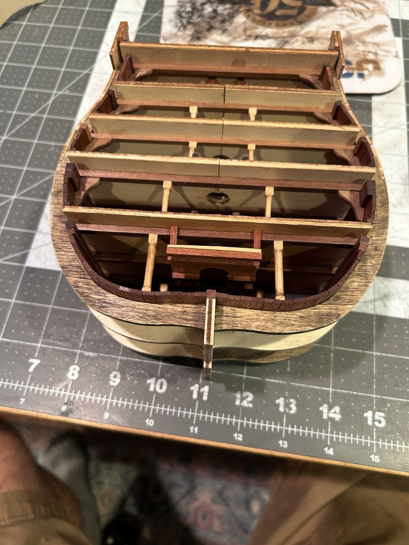
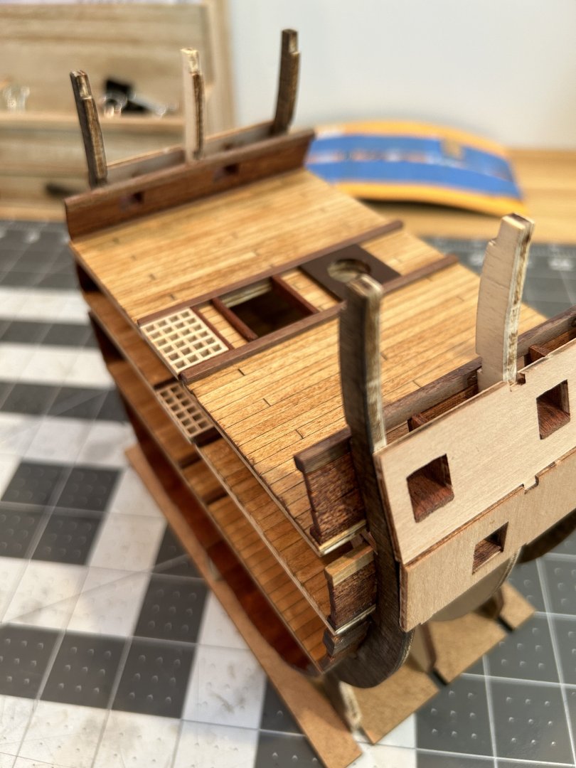
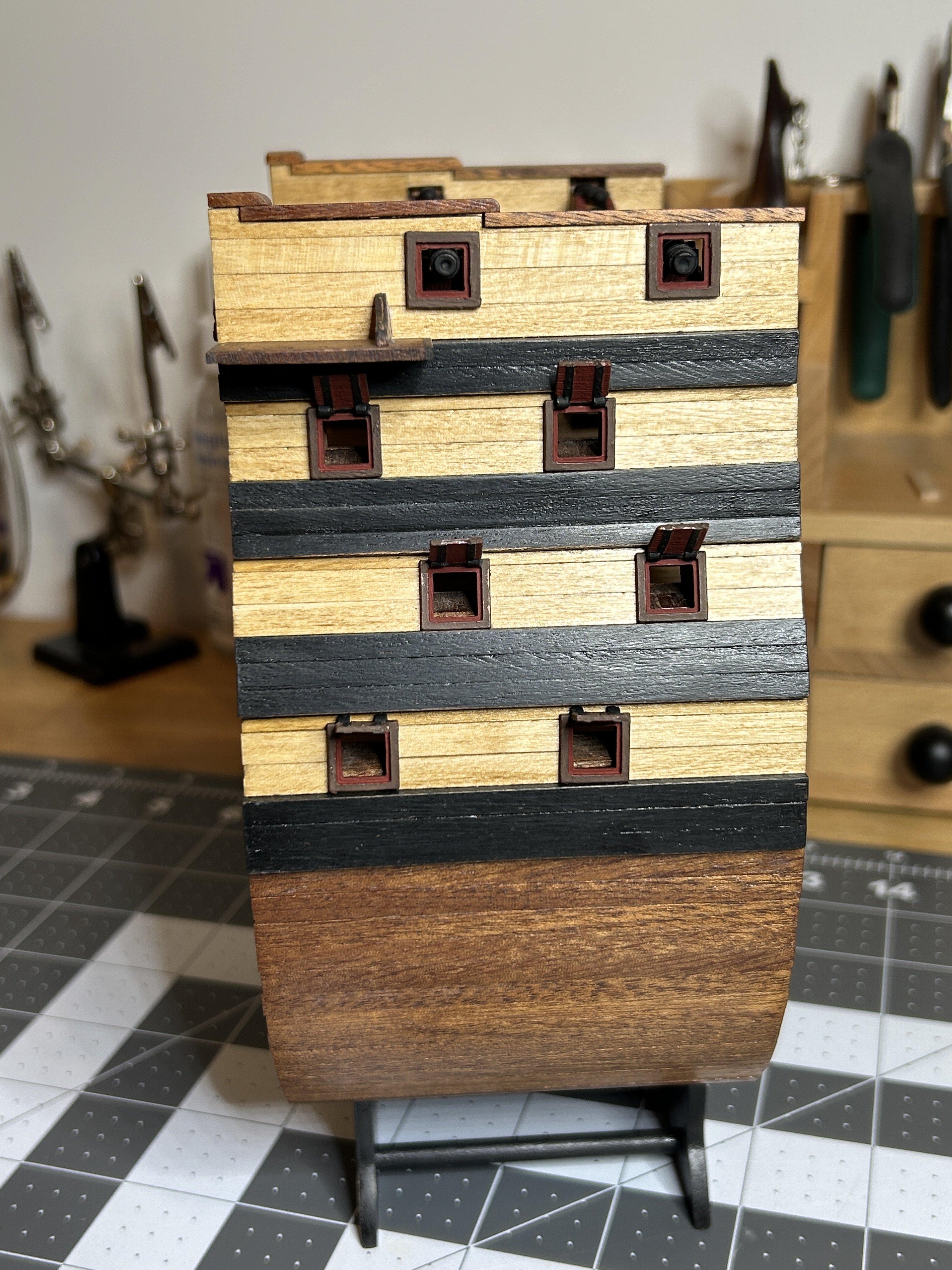
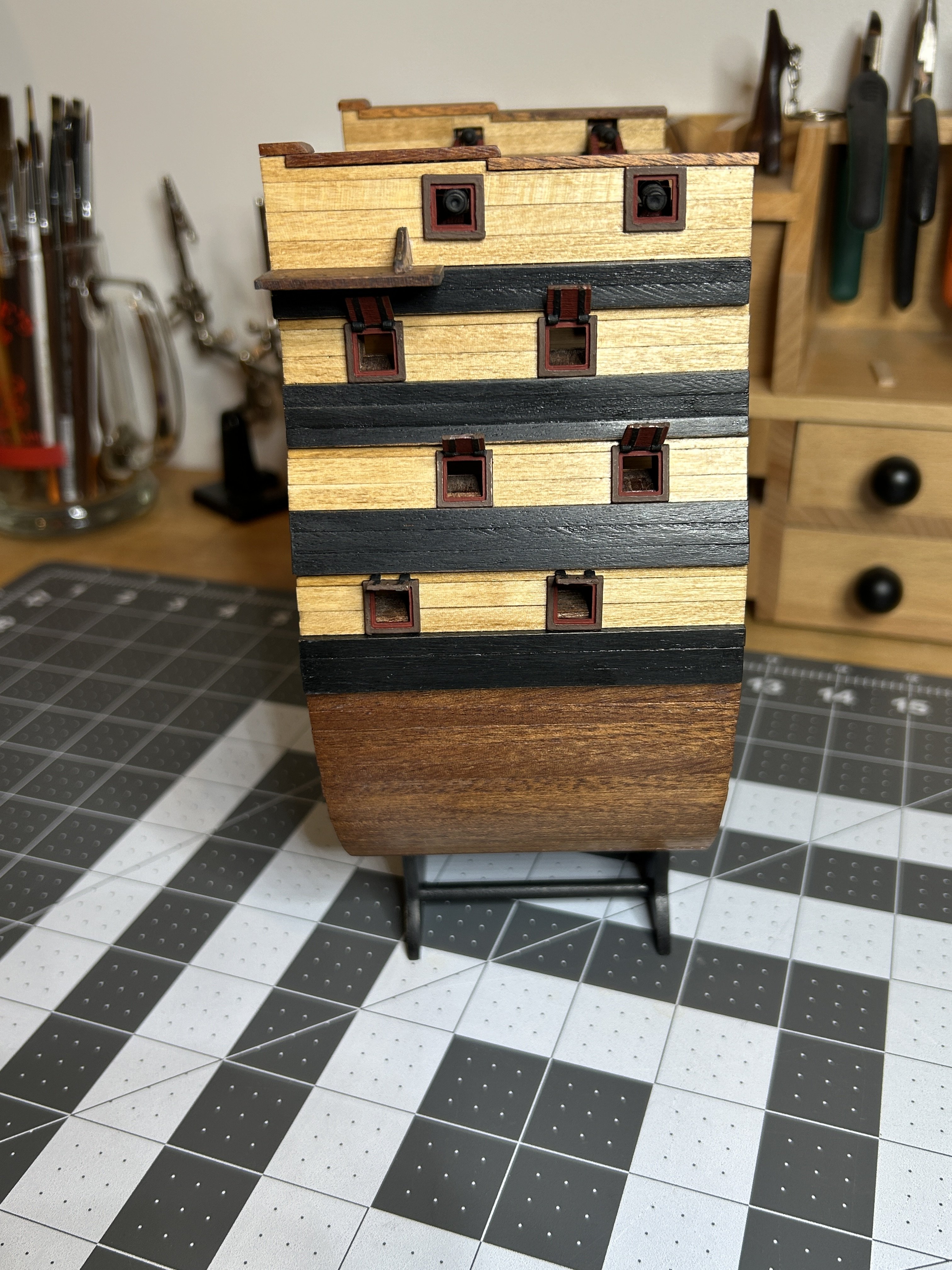
On my last post I said I would be getting back to my Frigate Diana, but I found myself continuing to work on the Santisima Trinadad. I completed the planking on the exterior of the hull, painted the gun port hatches, added the cap rail and secured the cannons on the top deck.


Painting the gun ports was a challenge given their size. They are about 10mm in width. The hinges are slightly wider than 1mm and the rabbet is less than a mm. With my eyesight it was all done under a 3x magnifying glass.
In an earlier post I discussed my concern with not pinning the cannons on the lower decks, I ultimately chose not to as I didn't want the cannon barrels protruding before I sanded the exterior of the hull and now I do not have access to pin them. I will do my best to secure them to the deck with some clear PVA glue. The four cannons that are mounted on the upper deck are pinned to help secure them to the deck.
Next up is the adding the ladders to each side of the hull. These will be made up of 76 pieces that range in size from 6 to 18 mm in length. My Ultimation tools were a huge help in cutting those small parts to right lengths. I used the chopper on the longer pieces, but on the really small ones I used the Repeater with the sander to get the lengths precise and consistent.
Life continues to be busy away from the shipyard, but I will get in to work when I can. I will say again that my intention is to get back to my Frigate Diana, but who knows which model I will feel like working on when I find a little time to work.
-
Looking good. Are you planning on staining or painting the exposed parts of the frames? If so it may be easier to do that now than after more interior planking is added,
-
Good luck on your build. I am a little bit ahead of you on mine, but will follow along.
- Paul Le Wol and Cleat
-
2
-
Really excited to follow along on this one. Thanks.
-
How thick are the blades on those knives? The single bevel ones are interesting.
- Canute, thibaultron and mtaylor
-
3
-
Occre sent out an email today that said there are only 50 of the limited edition HMS Victory models left. That means that 949 have been sold. Unless I missed it, I don't think we have seen a single build log for this model or the new Artesania Latina version of the Santisima Trinidad. With 949 of the HMS Victory sold, it is hard to believe at least a few weren't purchased by a Model Ship World member. If anyone is building either of these models, please consider starting a build log. I would love to see one of these being built and I suspect there are others that feel the same. If I missed a build log that already exists, I apologize.
-
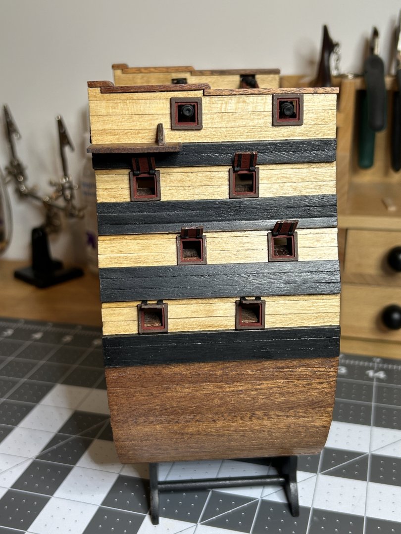
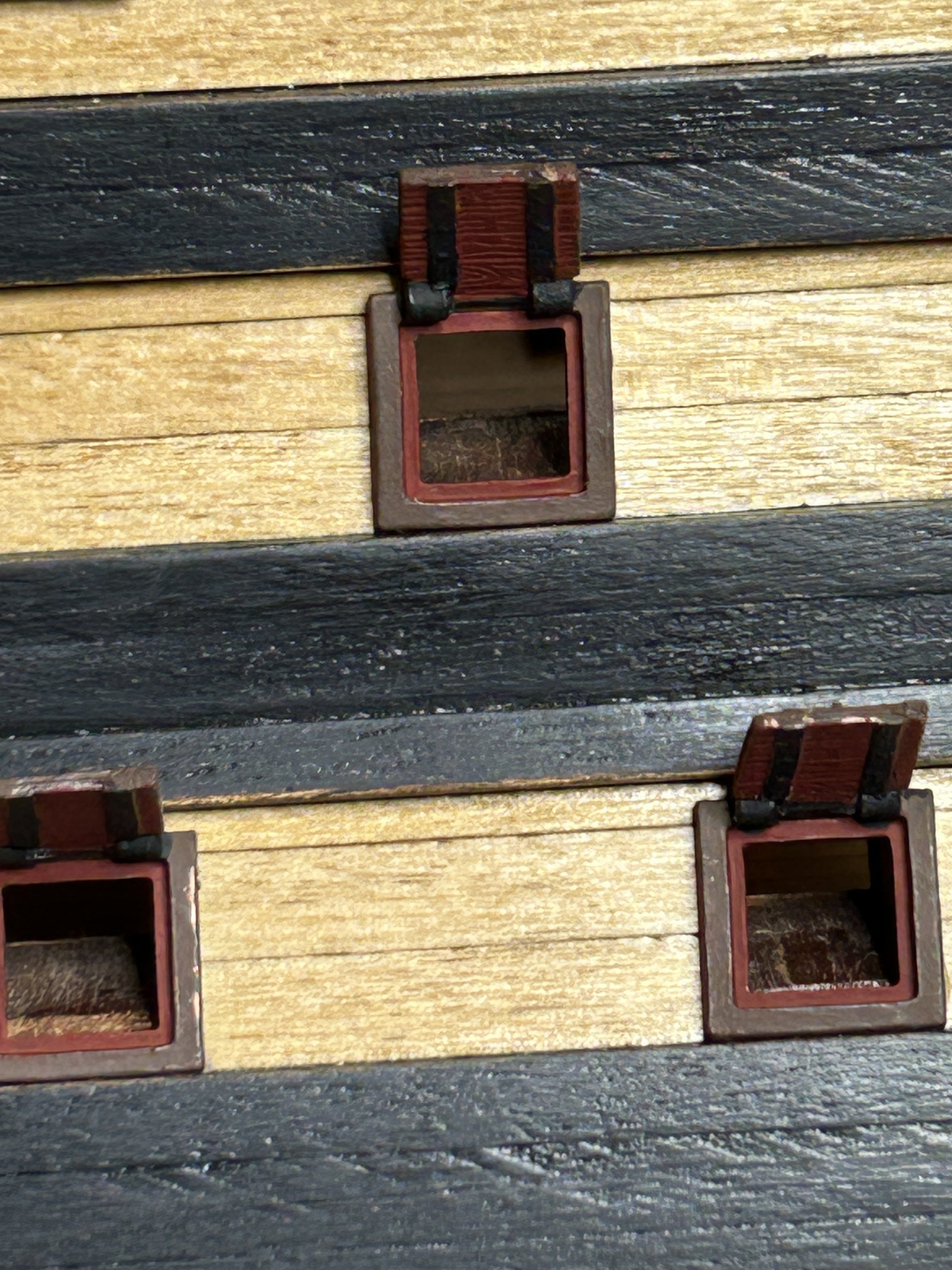
I have the four bands of 4x4 mm planking and the 2x5 mm Sapelli installed. The sapelli covers the lower part of the hull below the wales.
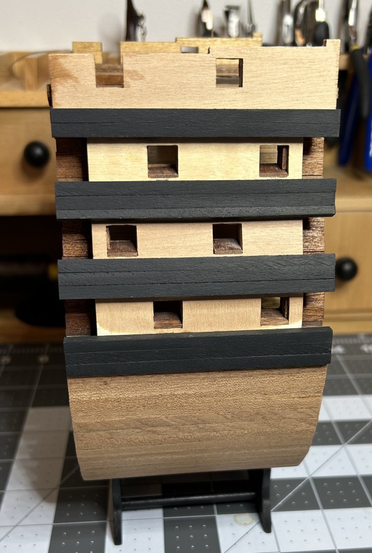
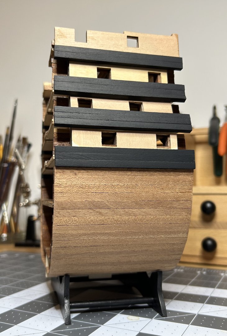
the 4x4 walnut is painted black. I experimented with black stain, but settled on the paint. The planking around the gun ports will be lime wood stained golden oak, the same as the deck. All of the planking will get a couple coats of shellac when the planking is complete.
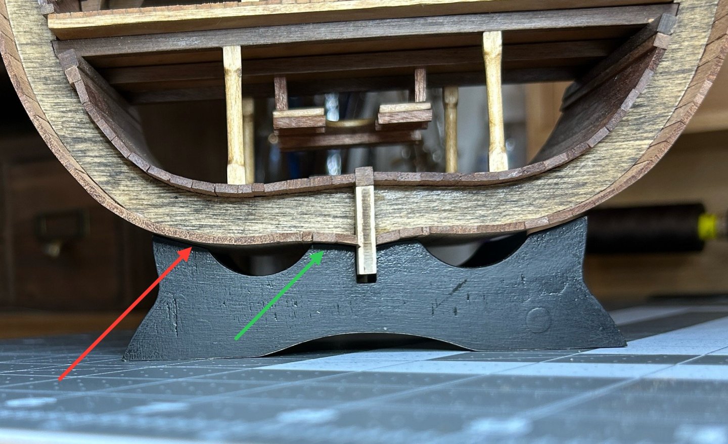
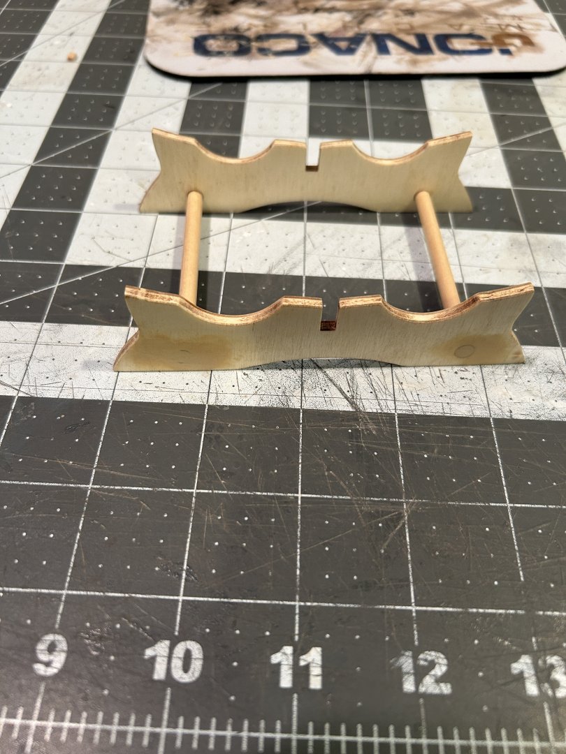
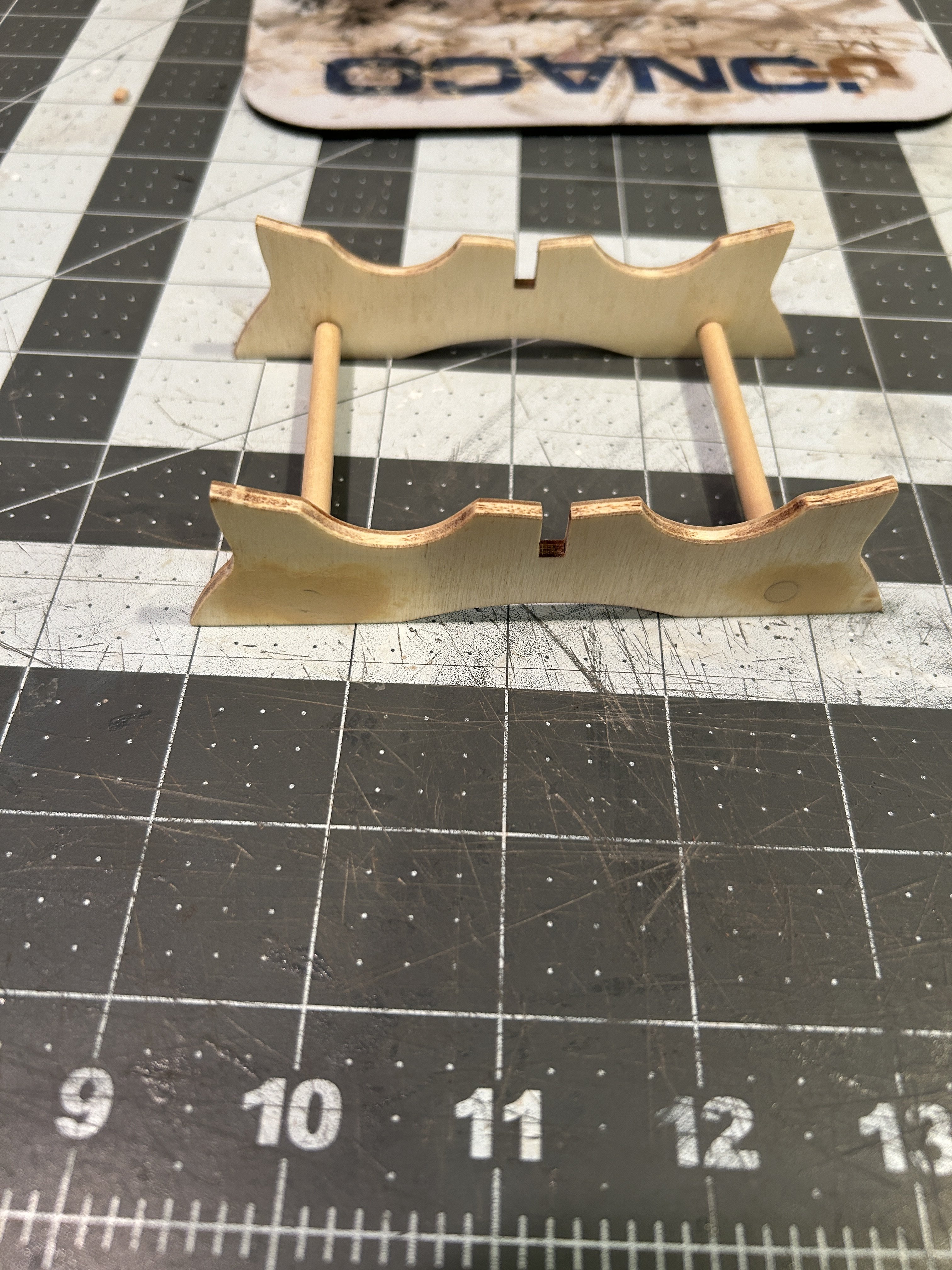
The cradle needs a little adjusting to keep the model from rocking. There are gaps where the cradle meets the hull on the outside of the cradle (red arrow). I will sand done the inner contact points (green arrow) so the model settles onto the outer contact points.
I will be taking my time on the planking around the gun ports and at some point I will get back to my Frigate Diana also, plus work is going the be busy the next 3 months or so with some special projects, so this may be my last post for awhile.
thanks for all the views.
- ccoyle, Zarkon, JacquesCousteau and 1 other
-
4
-
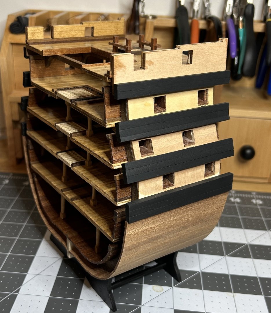
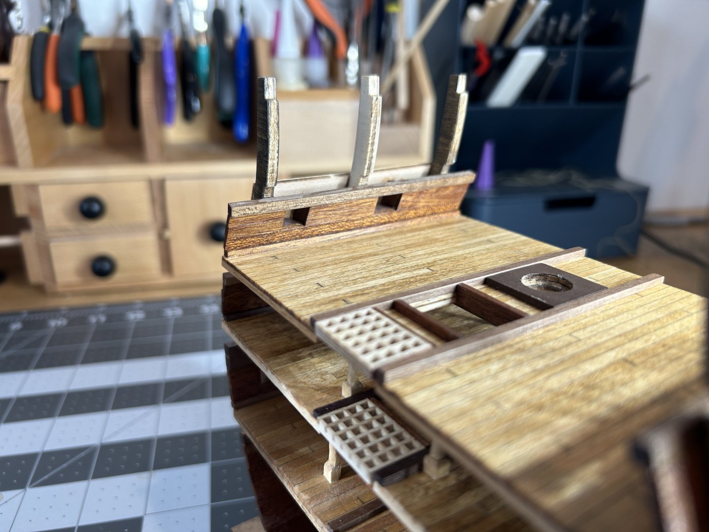
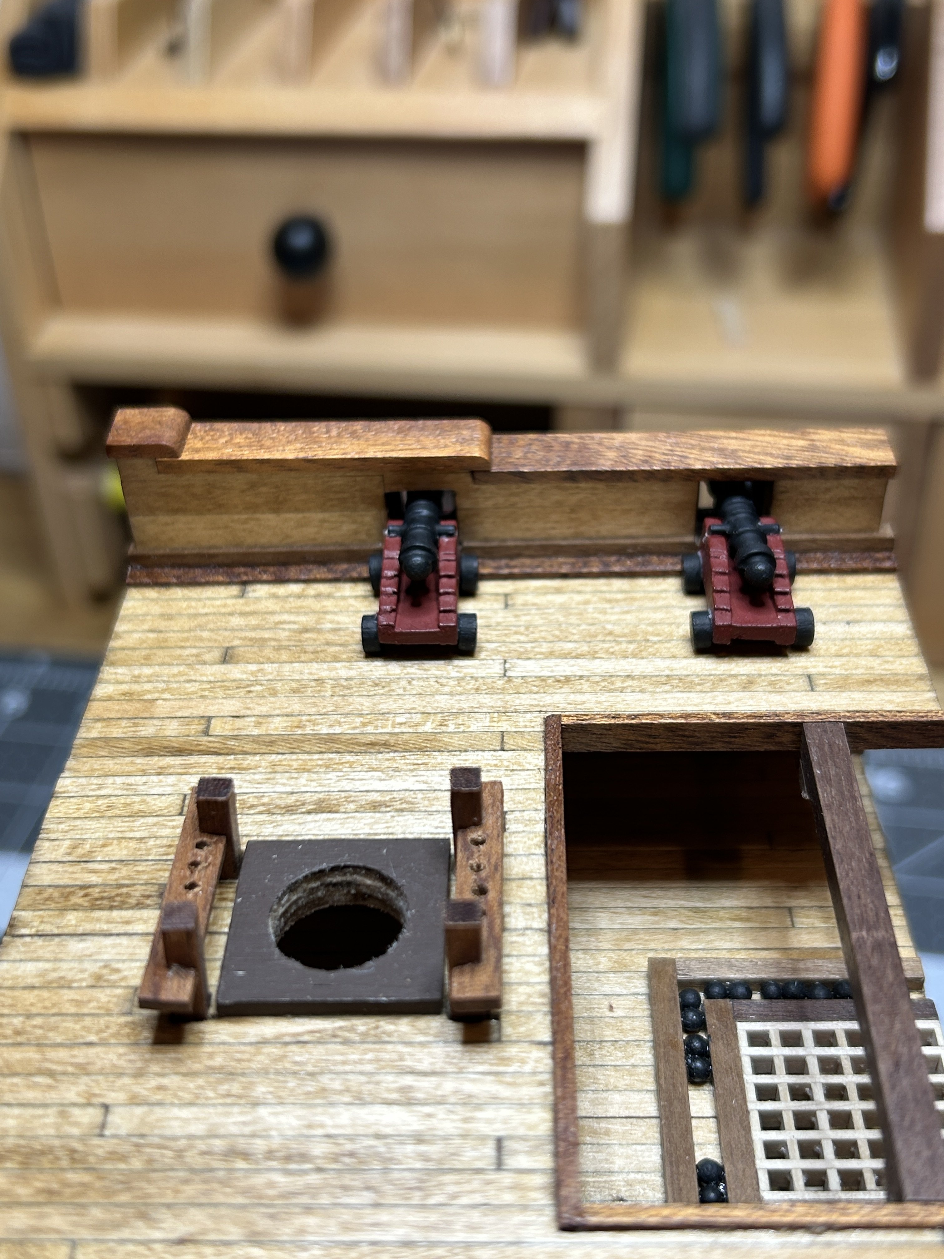
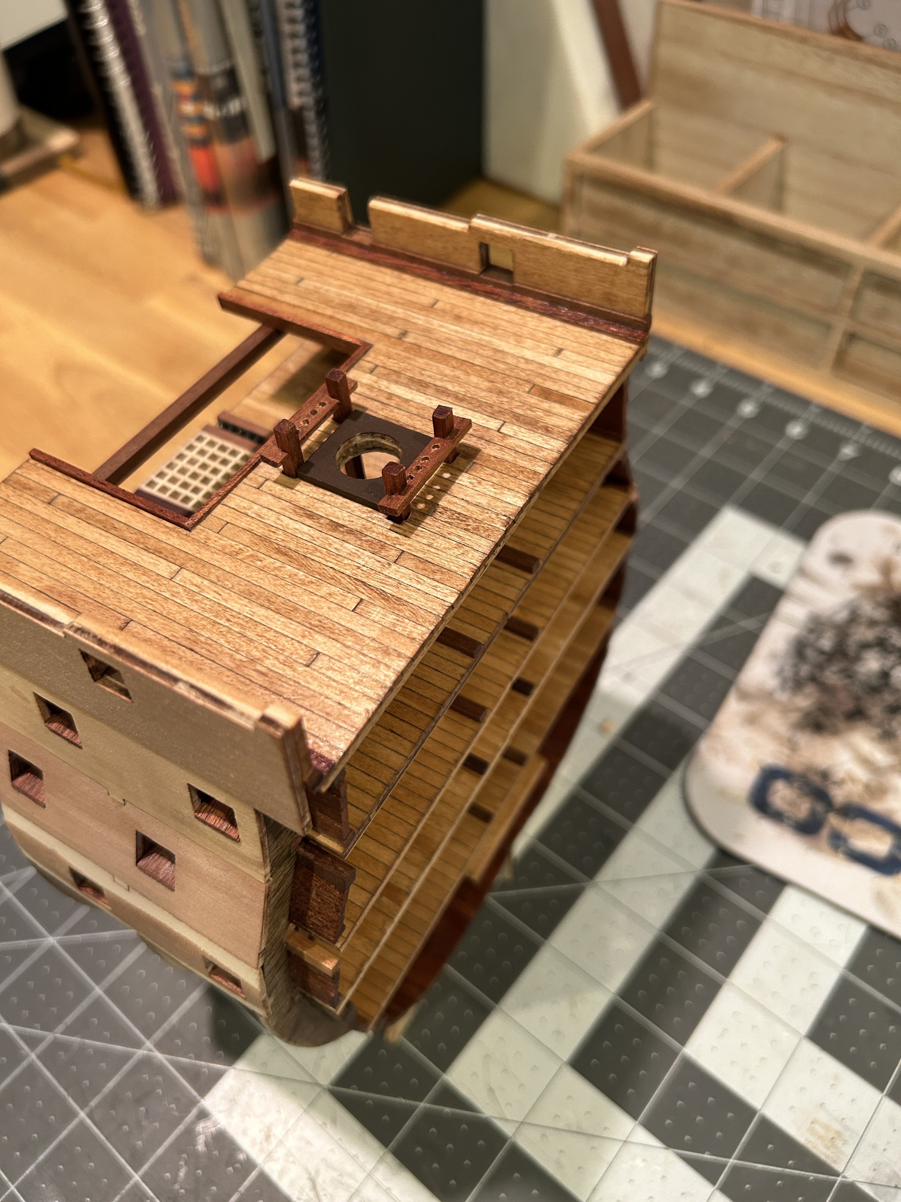
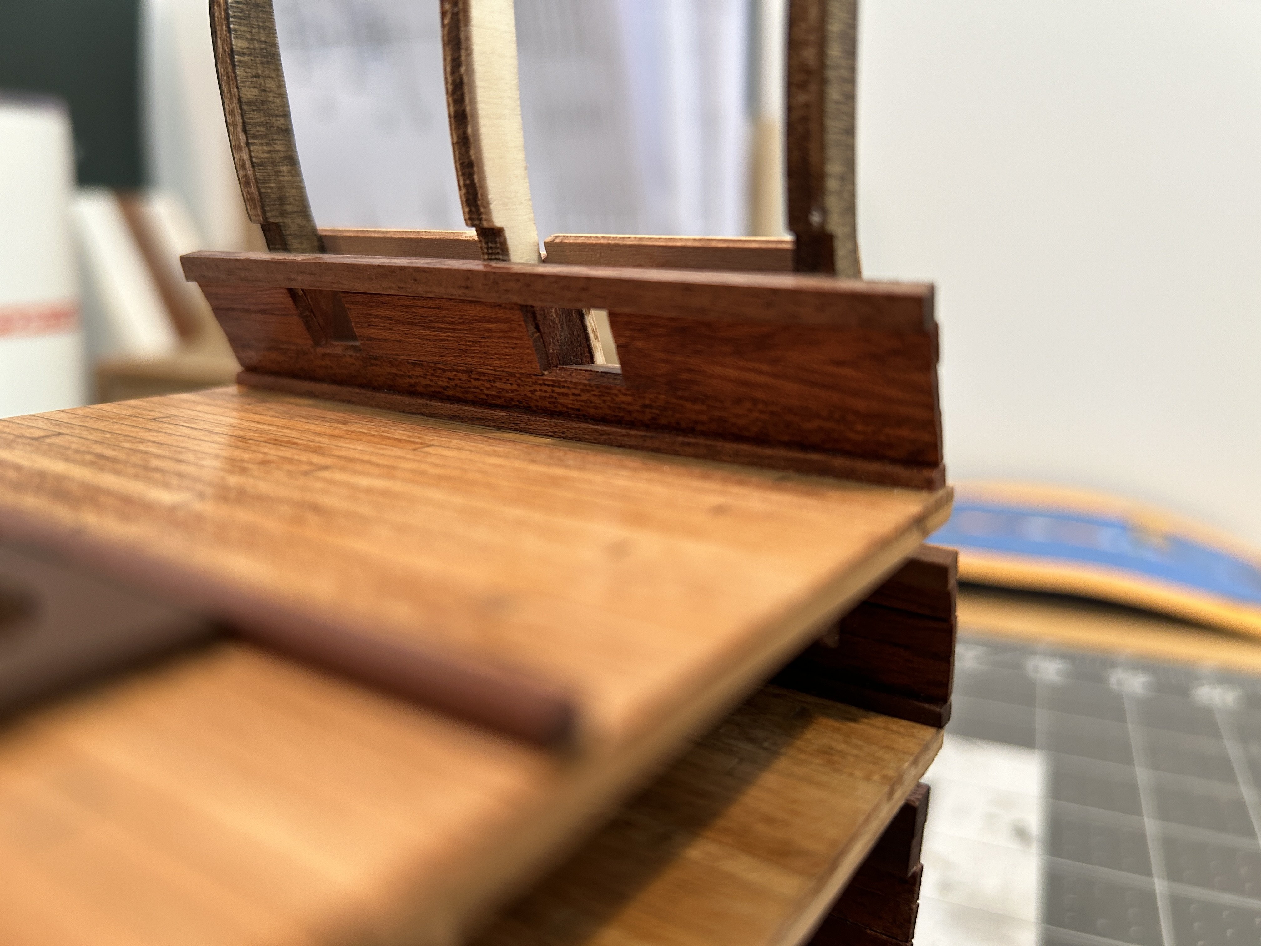
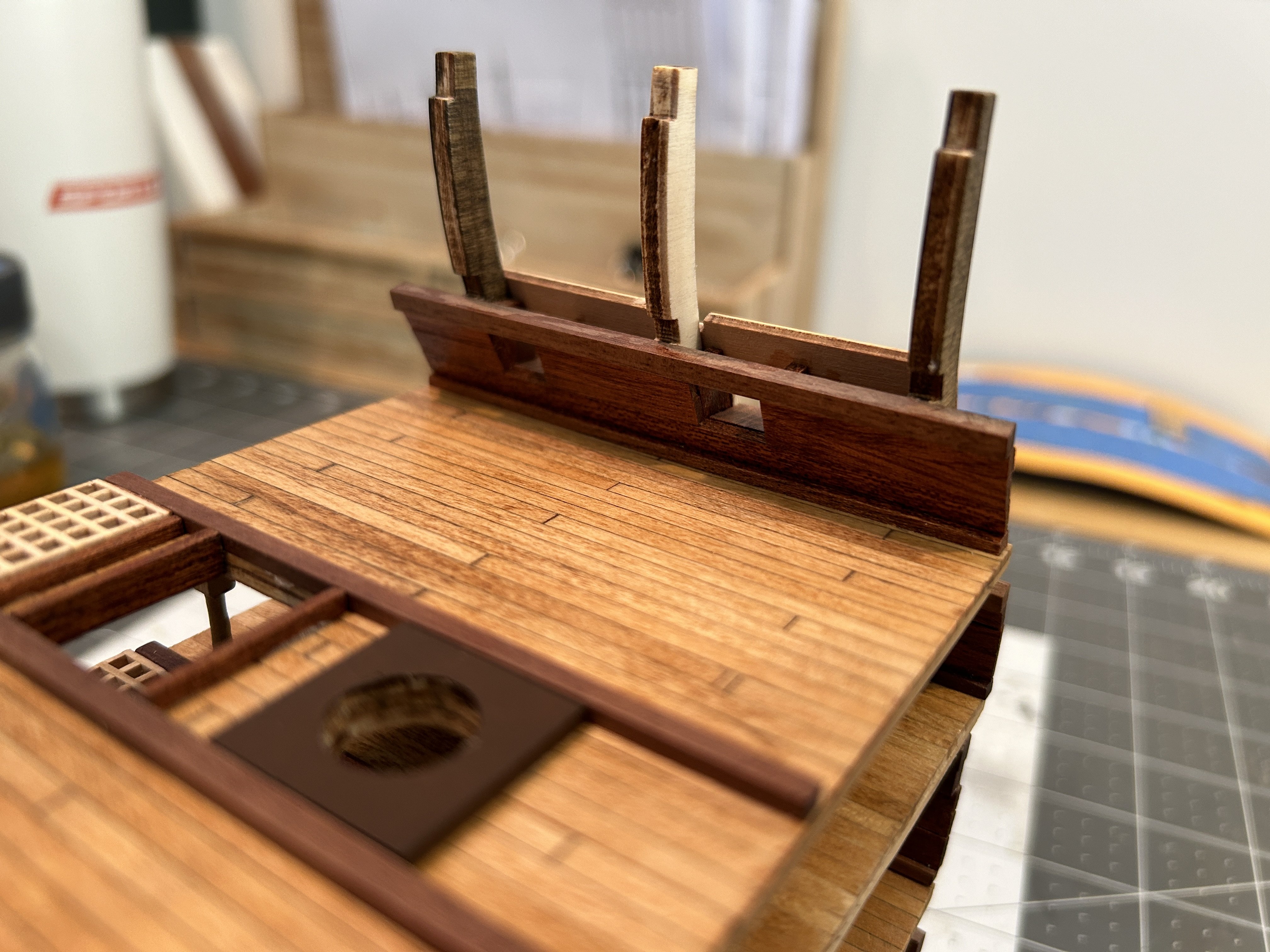
I have added the the pin racks to the upper deck and stained the inside of the gunwales. This was pretty straight forward. I need to use a small square file to open up the holes for the pin rack posts to extend down to the next deck.

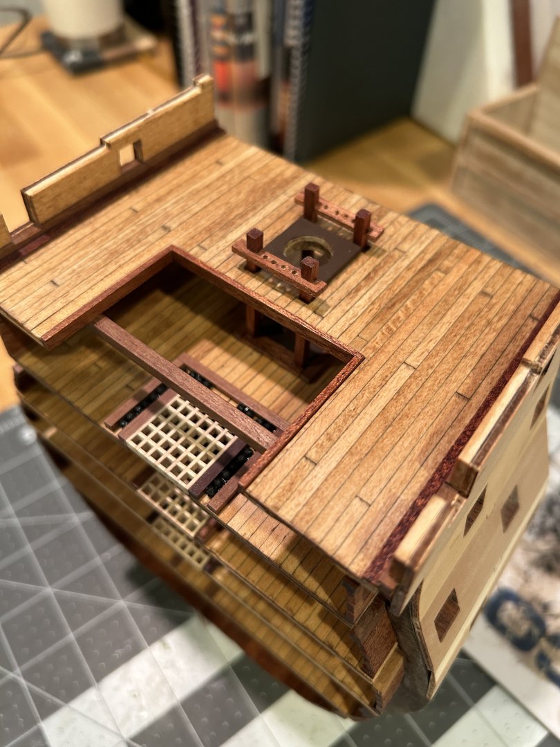
I am now at the stage where I need to cut the model from the building board, so I have started assembling the display cradle. I am going to paint it black after a coat of shellac as sealer. There has been some interesting discussion about using shellac as a sealer. I have had great luck using schellac, but the water based sealer that Vaddoc suggested looks interesting. I use a coat of shellac and then sand with 600 grit sandpaper.
I used the cutoff tool on my Dremel and then the disc sander on the Dremel to smootout the excess material left on the frame.
Now on the the planking. There are several bands on the ship that are planked with 4mm x 4mm material. The balance is planked with 2 x 5 mm lime wood and Sapelli.
The Ultimation Slicer will cut through the 4mm material, but is is pushing its limits and I don't get a nice clean cut on material that think. When I bought the Ultimation tools I purchased the Repetter for the Sander. I wasn't sure how much I would use it when I bought it, but I just used it to get the 4x4 mm planking material trimmed to length. I couldn't be happier with the results.
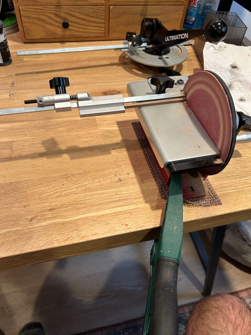
I would cut the material to a near net shape with a small saw and then use the Repeater to get the length just right. If anyone has any questions about the Repeater, please reach out.
Thanks.
- yvesvidal, Zarkon and Ryland Craze
-
3
-
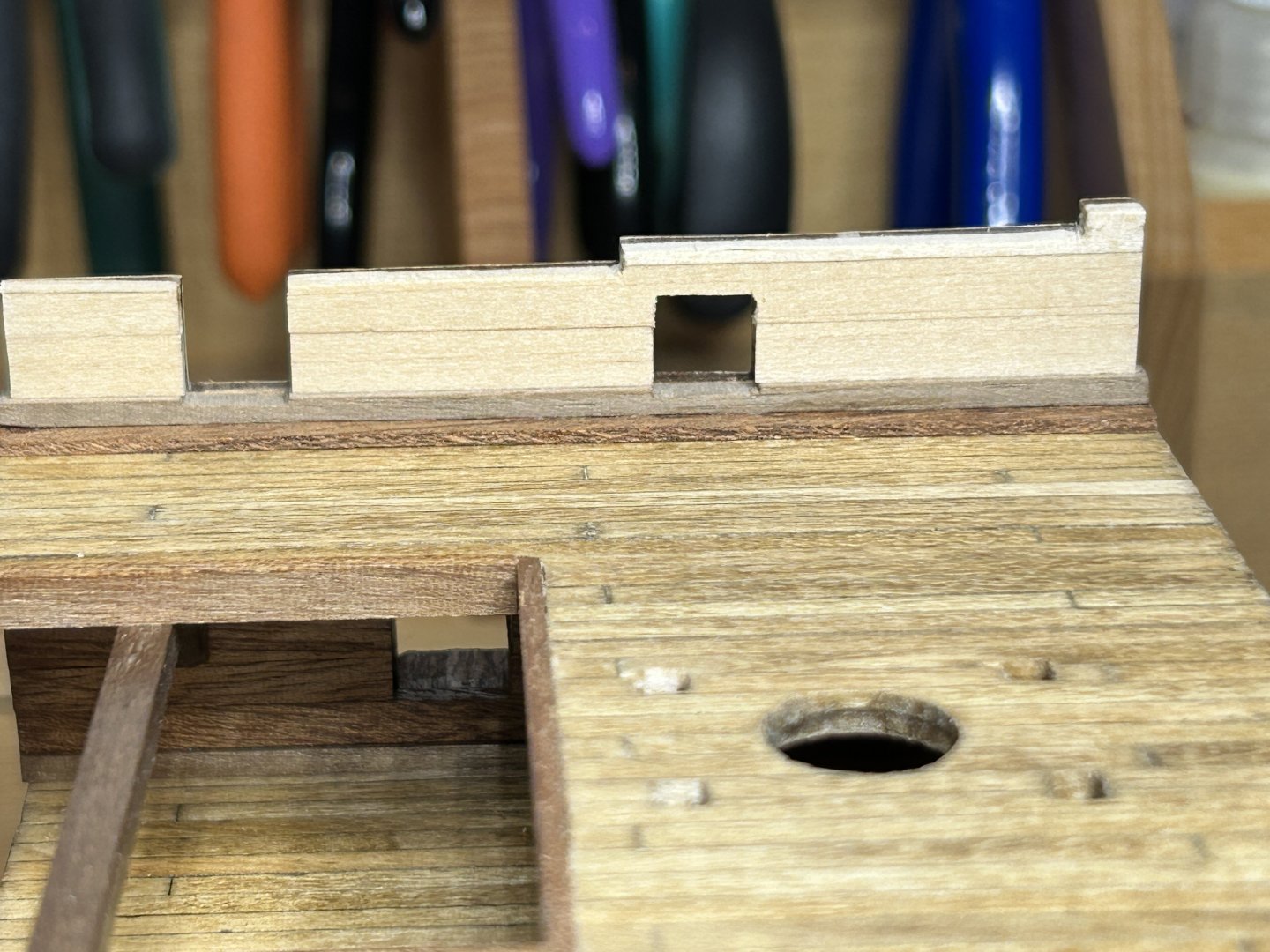
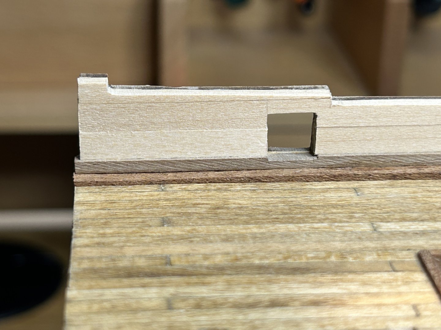
I will have a more comprehensive update down the road, but I was really excited with the way the lining of the interior of the bulwarks turned out and I wanted to post about it. I have been trying to learn to be more patient and take my time on the trickier parts. In his instructions for the US Brig Syren, Chuck says "Treat each planking segment as a small project unto itself". I think this is the first time I really took that advice to heart and I focused on each plank without thinking about the next one and took my time to get it right.
The material for this was 2mm x 5mm basswood. I had to notch out around the gun ports. below are a couple of pictures of the pieces I had to create.
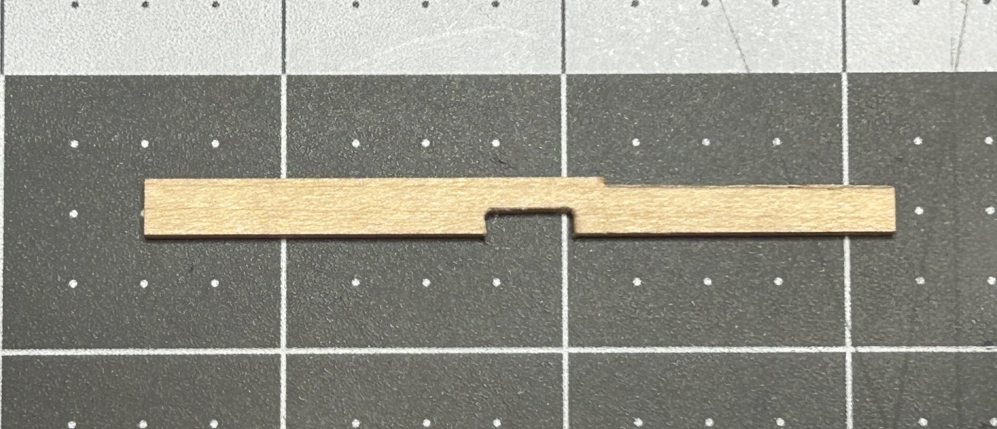
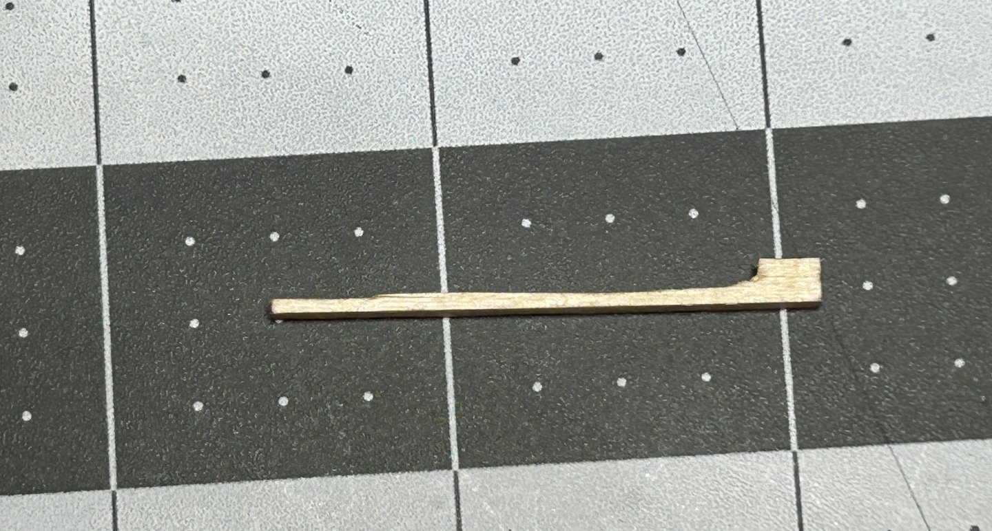
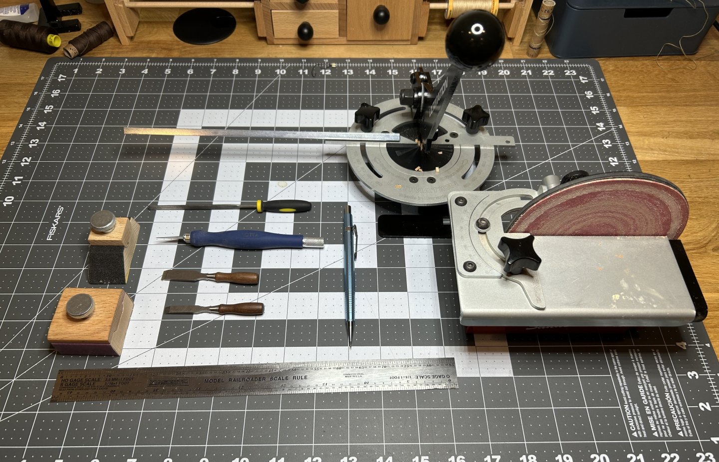
The second picture was before the final sanding and shaping. It took several tools for tool chest to fabricate these pieces including my Ultimation Chopper and Sander, two sanding blocks, a file, a hobby knife, two miniature chisels, a pencil and a ruler.
Here is the end result
Thanks for the views and likes, and I will get a more comprehensive post out soon.
- Zarkon, yvesvidal and JacquesCousteau
-
3
-
-
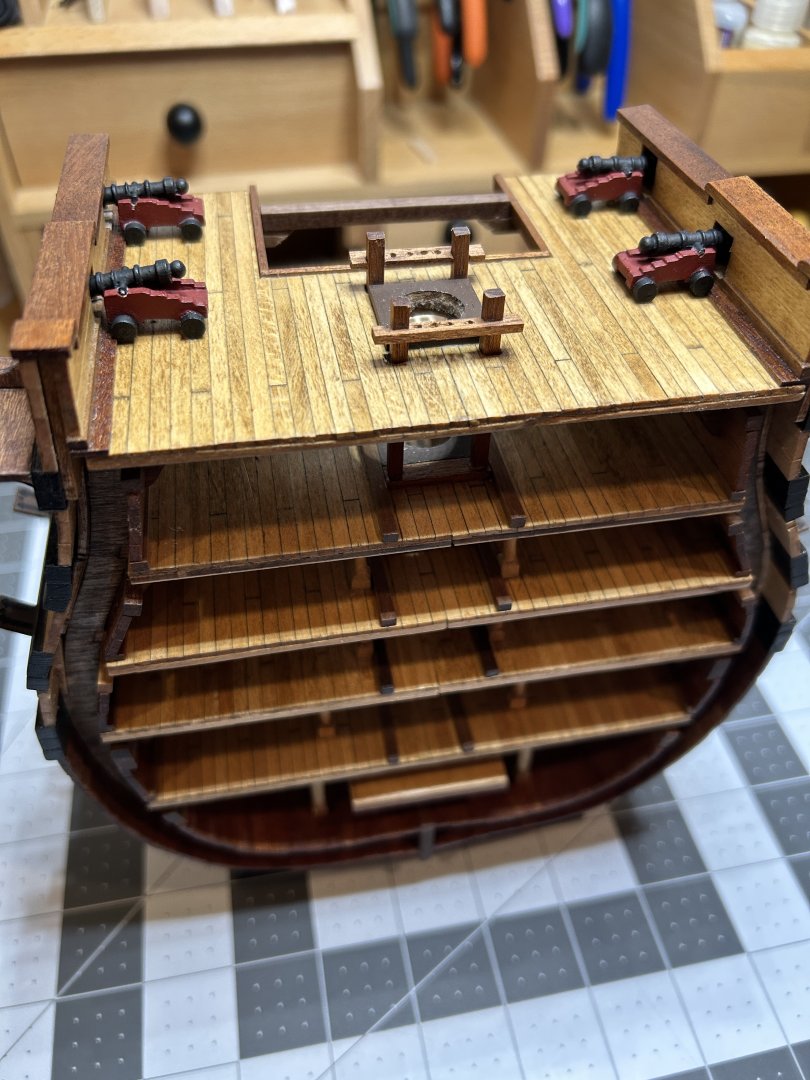
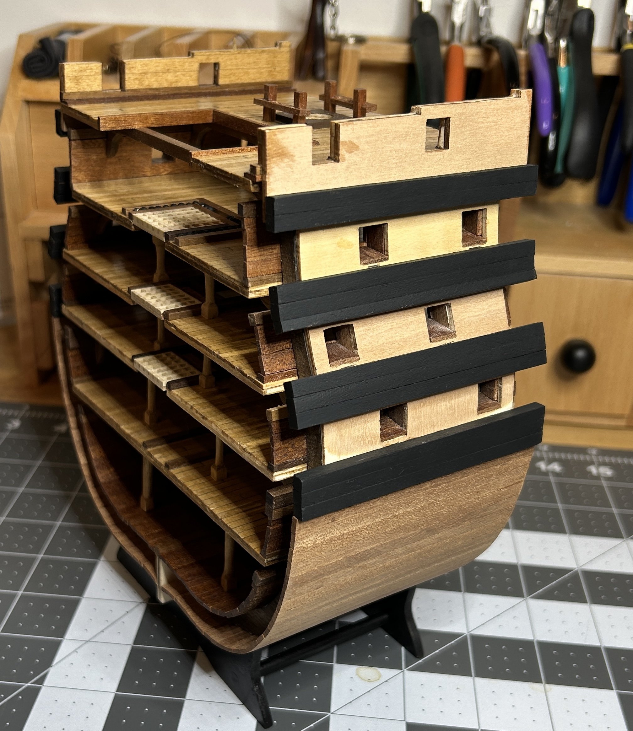
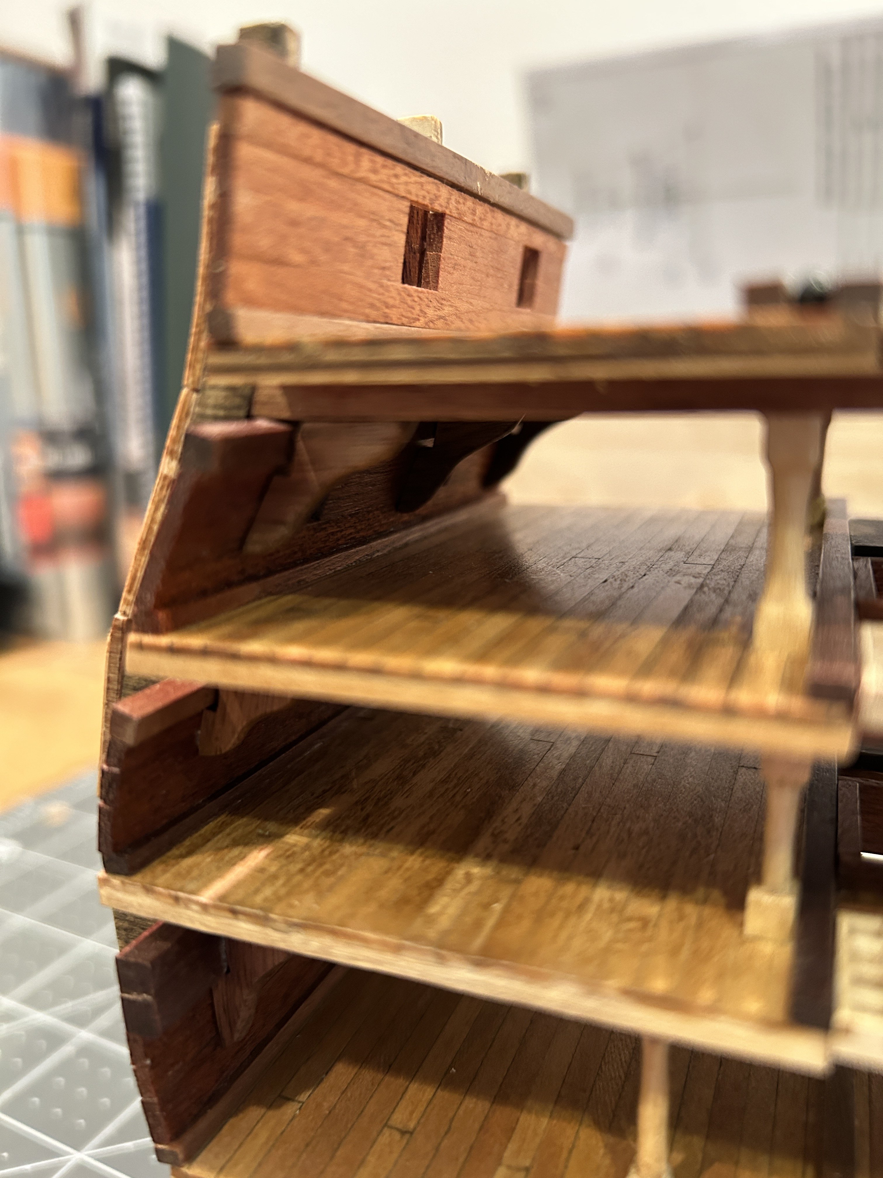
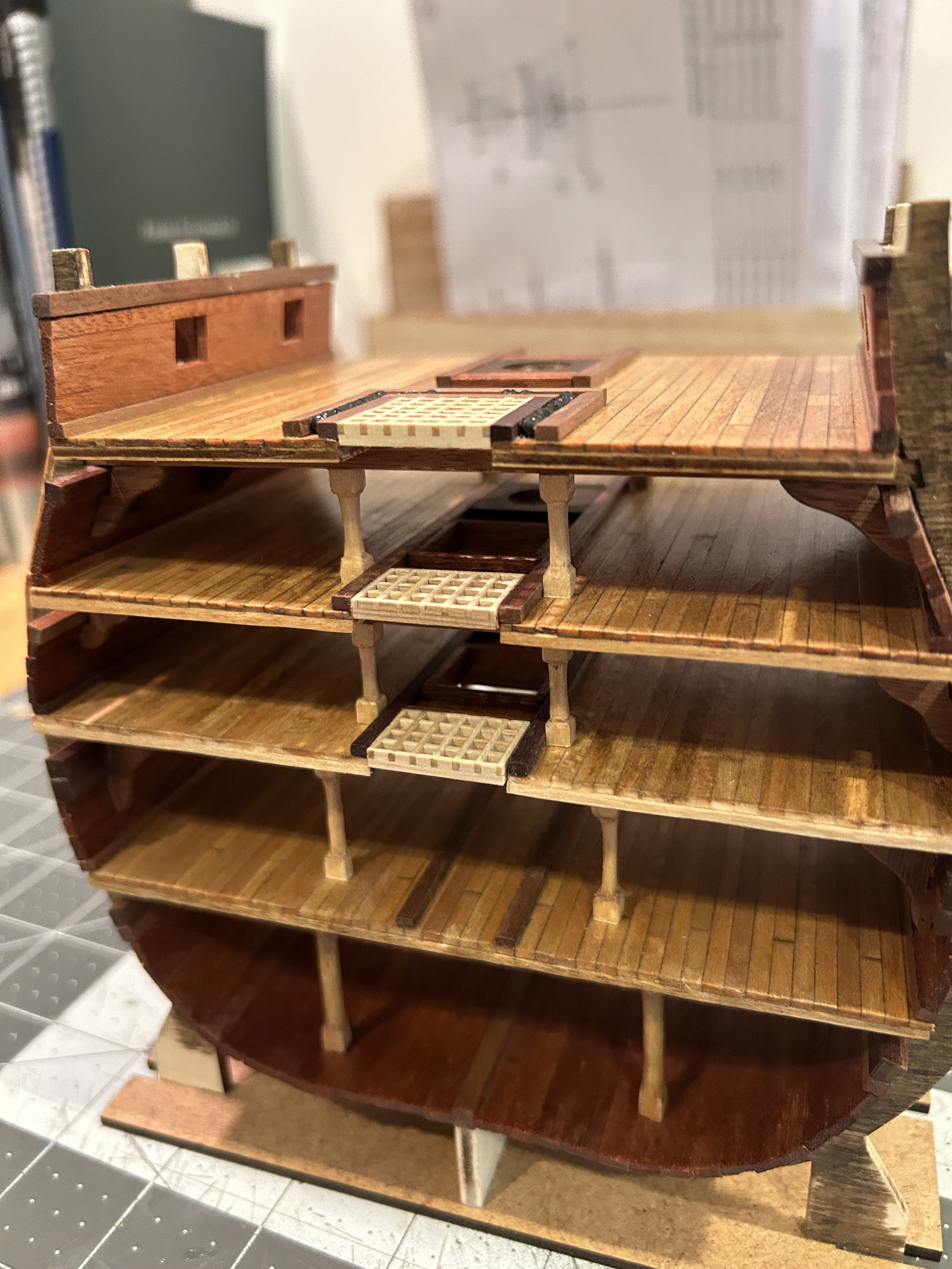
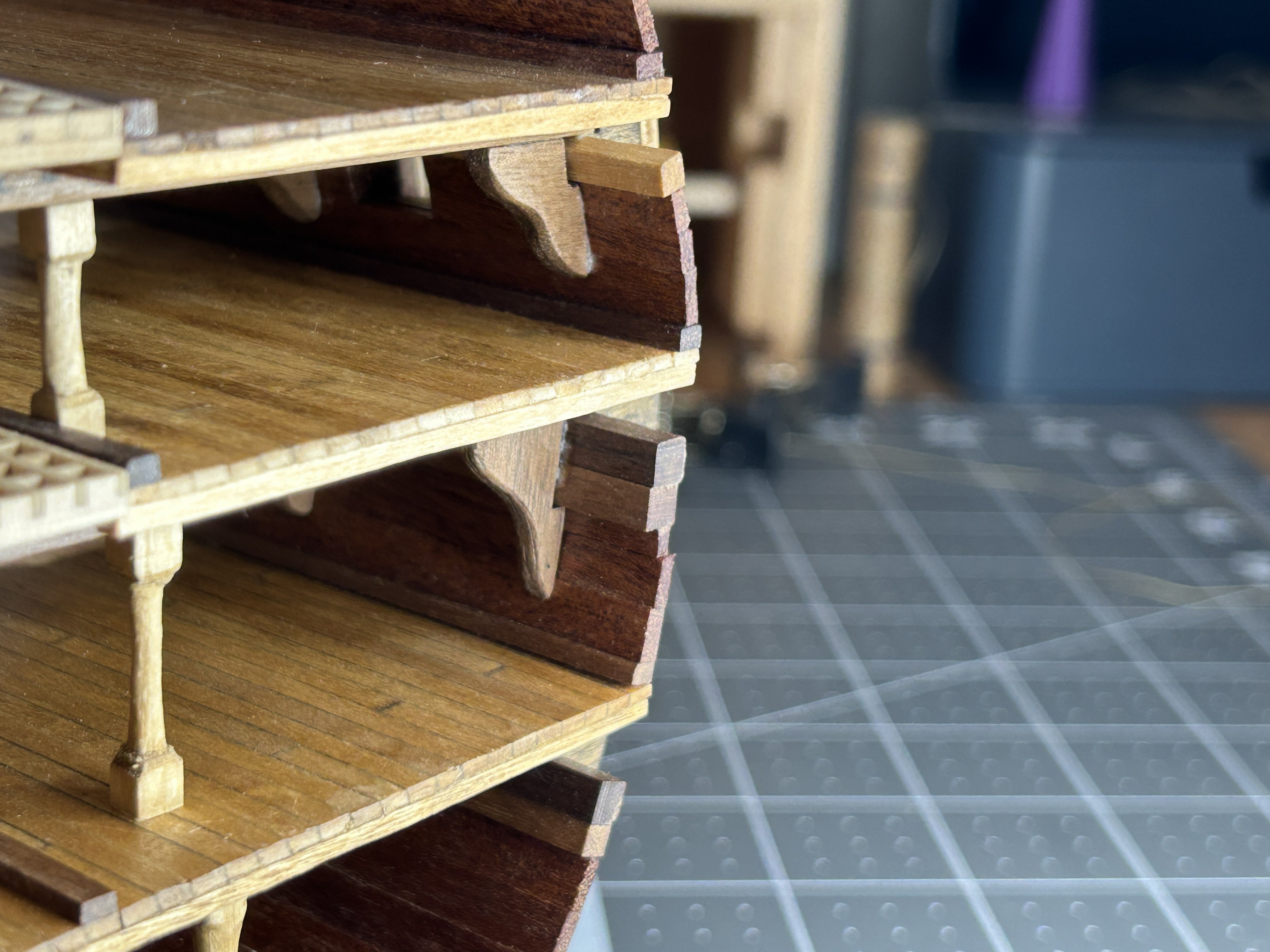
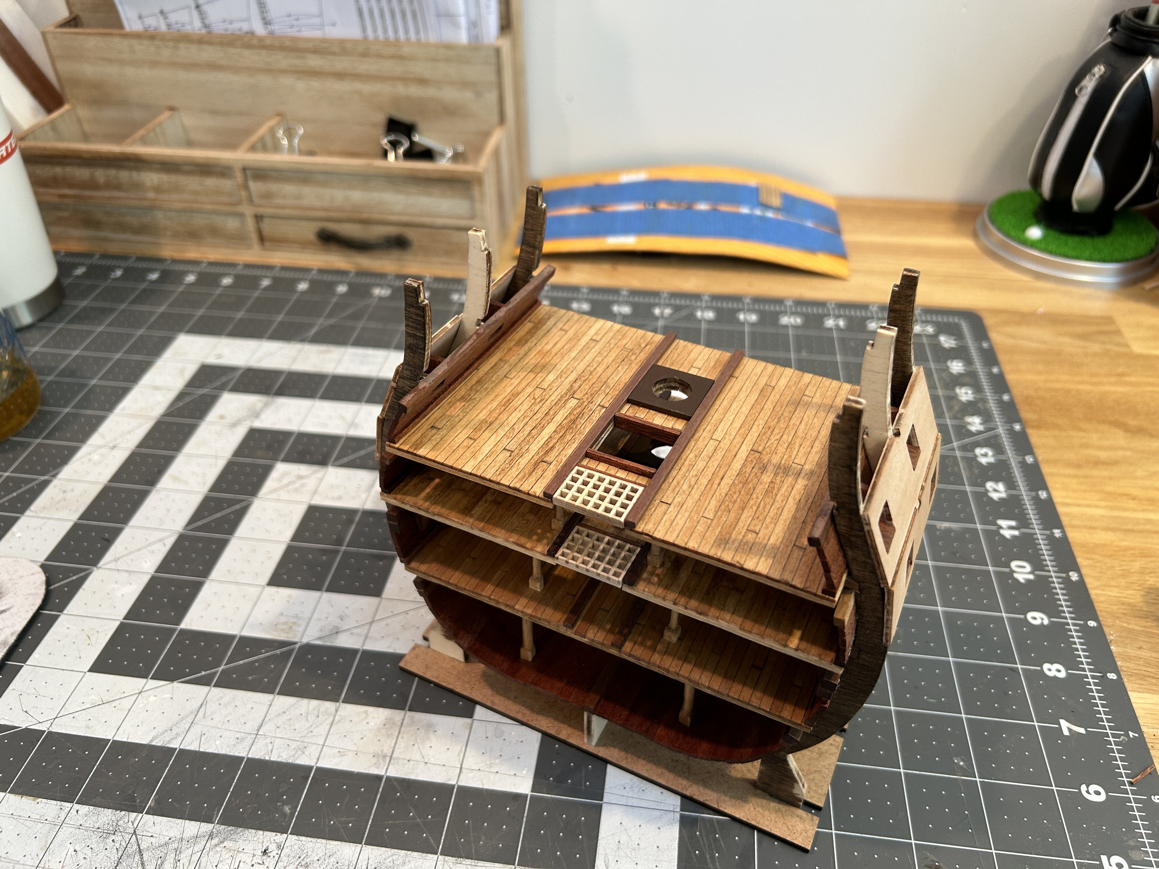
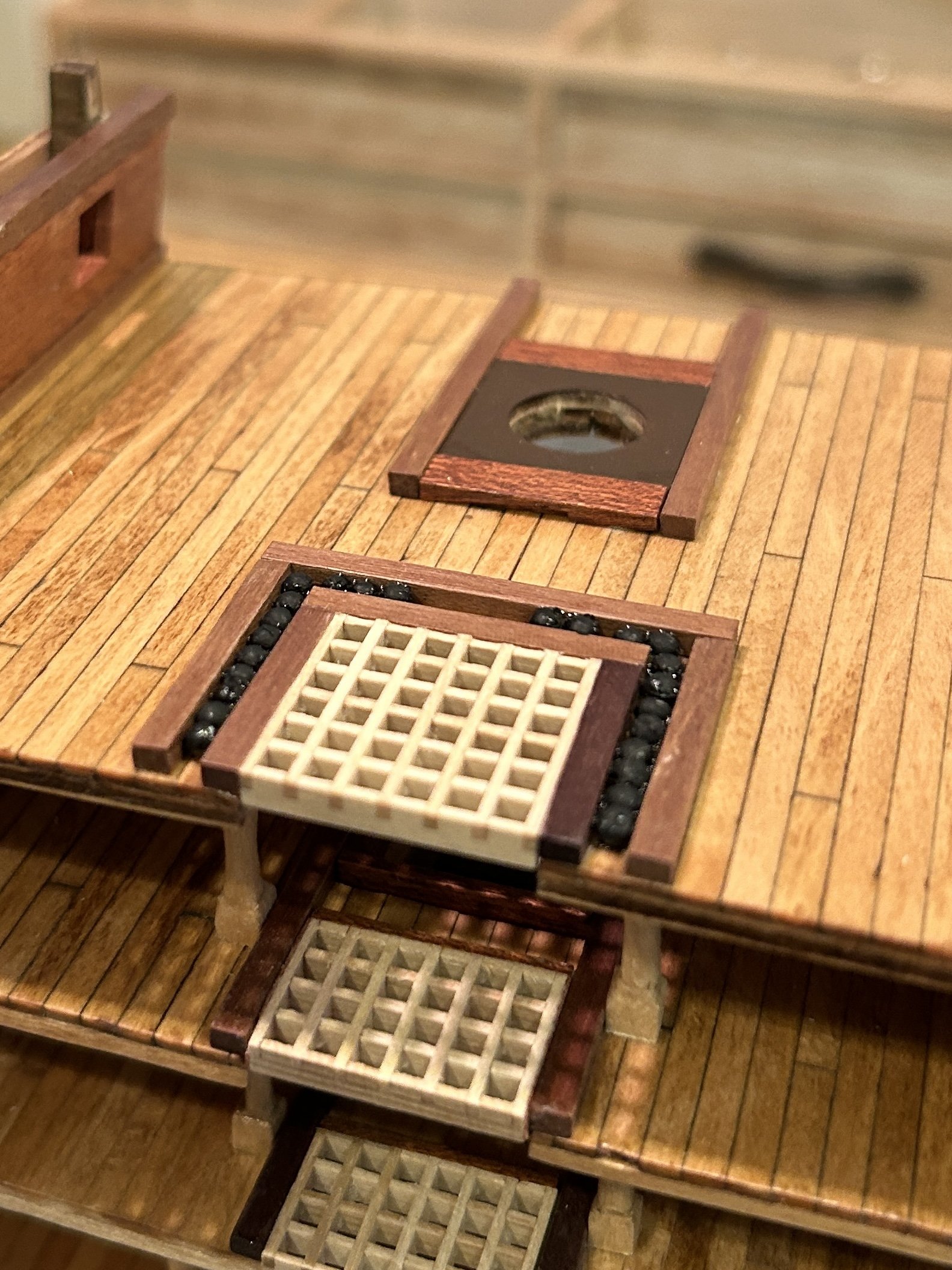
I have taken a break from my Frigate Diana and have spent some time with the Santisima Trinidad. I have added two more decks. The process was basically the same as the last deck.


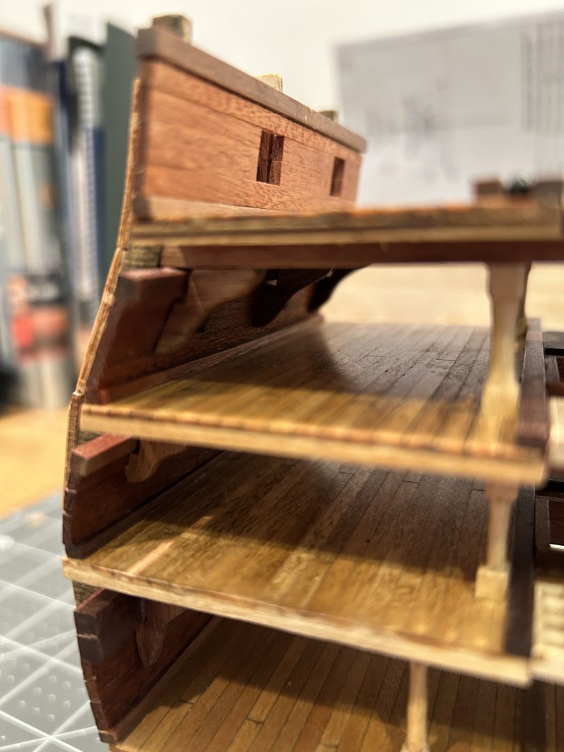


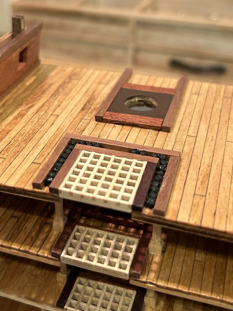
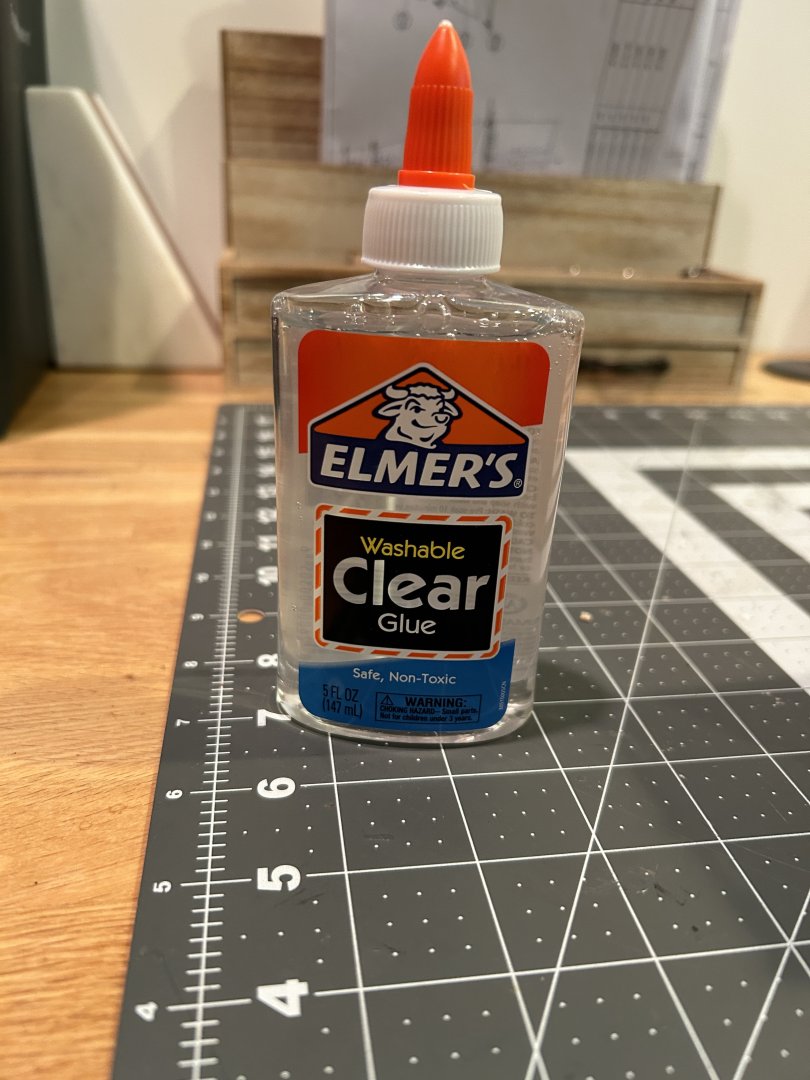
The shot garlands are the only unique feature on either of these decks. I used clear Elmer’s glue to secure the shot in place.
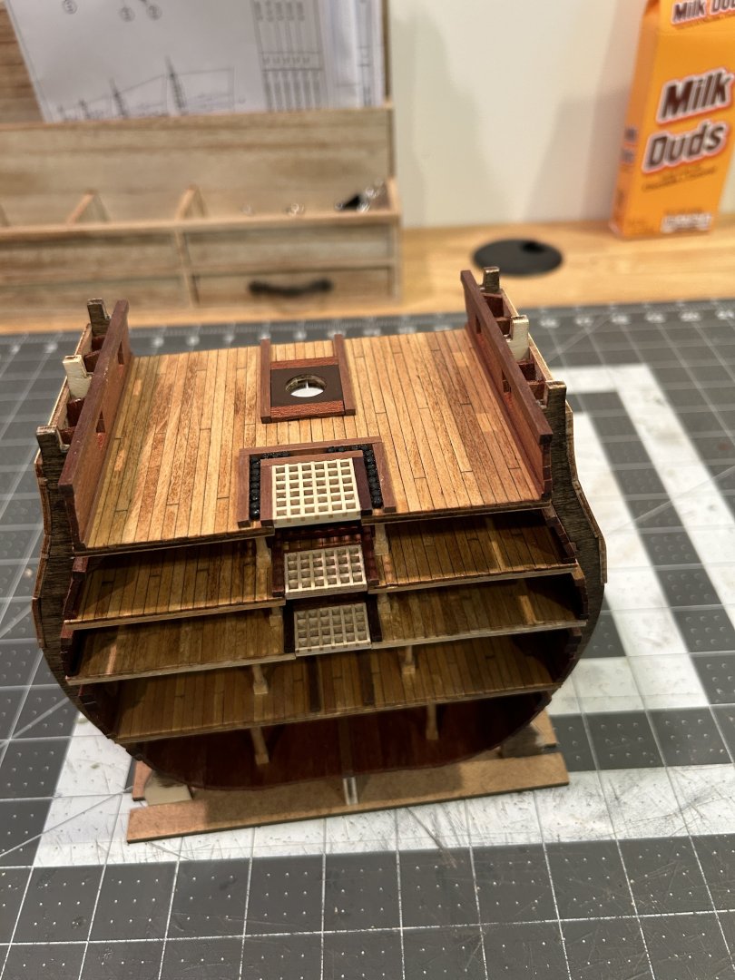
working on the top deck now.
-
12 hours ago, CPDDET said:
You could also check braided fishing line like FireWire by Berkley.
Is it difficult to tie knots with these lines. I don’t fish anymore, but 30 - 35 years ago I tried these lines for fishing and you needed to use special knots or the knot would unravel because the nature of the material.
- mtaylor and Keith Black
-
2
-
It has been awhile since my last update. I have the jib sails and the fore royal sail and fore top gallant sail installed. I am achieving the look I wanted with the sails. One concern I have with the method I am using create the shape of the sails is the potato starch creates a bit of a shiny surface on the side of the sail that it is applied. With the way I am planing on displaying my model the back side of the sales wont be visible, so I am not concerned on this model, but I would caution others to consider this if they choose to use this method.
.thumb.JPG.91475c37b9789aeb25e1c4b97ddc6afb.JPG)
.thumb.JPG.bb4bcd929bfe54a9c2120958054a4c27.JPG)
.thumb.JPG.ae3ff09bc0d58425ddc34b6d38527109.JPG)
.thumb.JPG.e8d0ac8097319100c4784d9723c0f85f.JPG)
The Top Sail is not fulling complete yet. I need to get the Fore yard installed to finish the top sail. For the Fore and main top sails and the lower course of stay sails, I will rig those sails furled instead of unfurled. I have seen this as being called "rigged for fighting". Not sure if it is an accurate representation of how a ship like this would enter battle, but I like the idea of being able get a better look at the deck on the completed model. I need to get some help from someone who sew to make the sails that will be furled smaller before I continue with those sails. Due to the over scale thickness of the sail material if I furl the sail as is, it will be way too big on the yard.
For attaching the various lines to the belay pins, I am taking the advice I say from a user on the site (can't remember who gave the advice) to run the line through the hole for the belay pin then install the pin to secure it. After I add a rope Hank you won't be able to see that the line isn't secured to the pin in the traditional way. At this scale I think this shortcut is the only way I would be able to complete the rigging. I am leaving the excess lines on for awhile In case I need to adjust any of the lines later.
I think In the future if I build a fully rigged model it will be a scale like 1:48 and not 1:85. I wish my eyesight was better, but at this scale the rigging is really challenging to me.
.thumb.JPG.e4f3dc82080e2ef37c6137c7be1abf04.JPG)
As always, thanks for all the views and likes. I will be shifting gears back to my Santisima Trinidad cross section until I can find someone to help me sew the sails that will be furled.
-
1 hour ago, Gregory said:
I've been getting by with a bigger benchtop sander, but I'm considering getting this one.
I think the only issue you will have is for really small parts the gap between the edge of the table and the disk might be bigger than you would want. Only an issue on really small parts and can be overcome be using a larger sacrificial piece of wood under the smaller part.
- Ryland Craze, Gregory, mtaylor and 1 other
-
4


.JPG.73ec19eeeb0e4a1e5d142efc764ac2b1.JPG)
.JPG.3ae576a0ff8ebd7af056b3bf57e301c1.JPG)
.JPG.d73adb7fc94567fce045c9b8b315a700.JPG)
.JPG.194742d965b640dbc1447235da2fa3d0.JPG)
.JPG.81e0f9d1a172e4f97bbc431a26ecc95d.JPG)
Acrylic paint tips and techniques
in Painting, finishing and weathering products and techniques
Posted
I have used shellac over water based acrylic paint with good results. I usually use the FolkArt brand craft paint. Available at the big box craft stores. I am sure it isn’t the highest quality paint, but it works well for me.