
.jpeg.882f0a147f14858c9e673da7e13d8ebe.jpeg)
RossR
-
Posts
308 -
Joined
-
Last visited
Content Type
Profiles
Forums
Gallery
Events
Posts posted by RossR
-
-
-
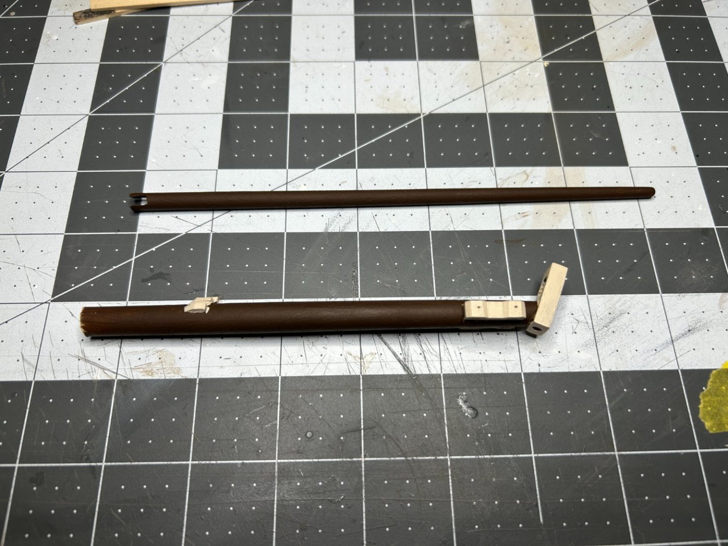
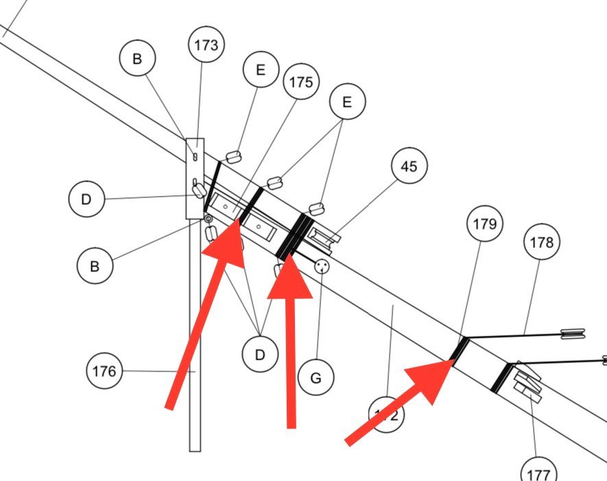
I have started fabricating the components for the bowsprit. I have also been assembling my Serv-O-Matic from Syren. I have a pretty good handle on what should be served on the shrouds and stays, but I am not as sure about some of the lines that are used to secure the components of the bowsprit. I have attached a photo of the plan for the bowsprit. Should the items that I pointed to the photo be served? I would appreciate any help anyone can provide.
-
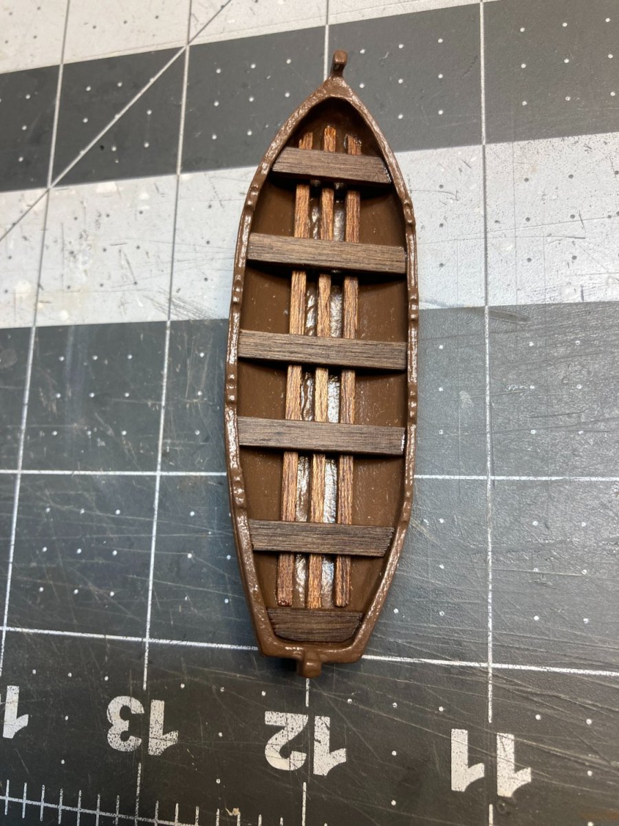
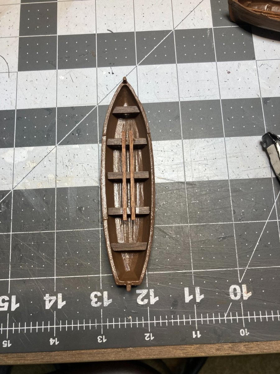
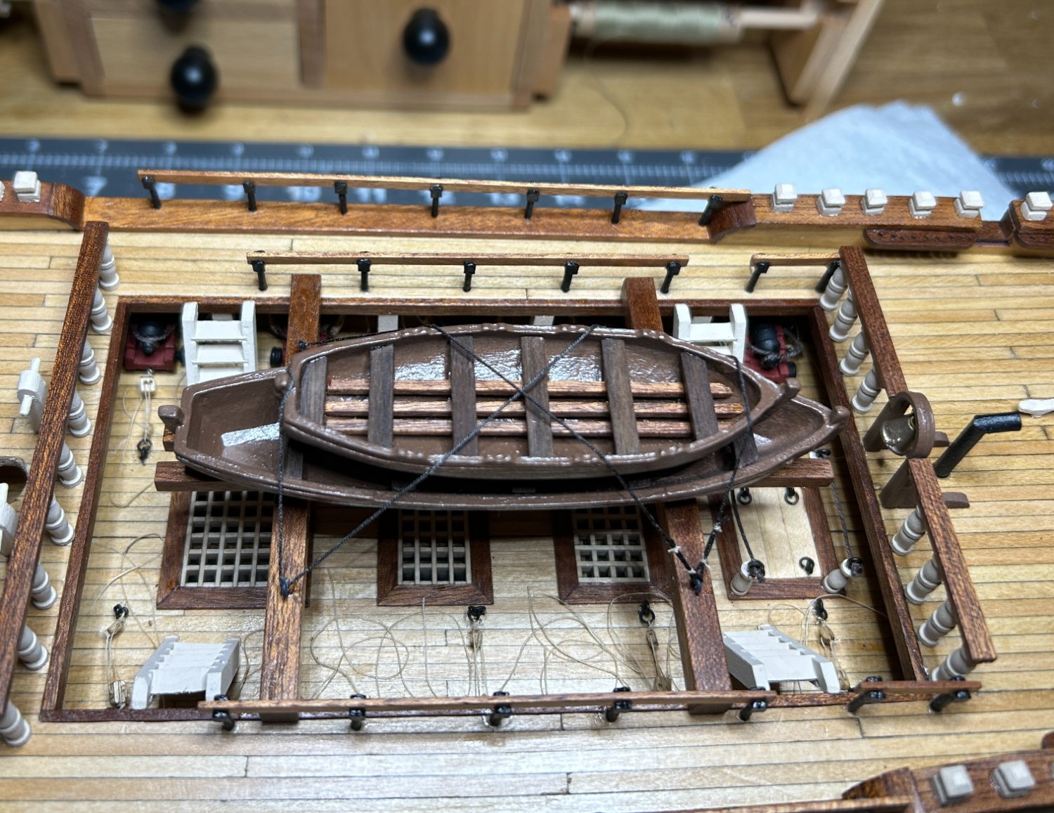
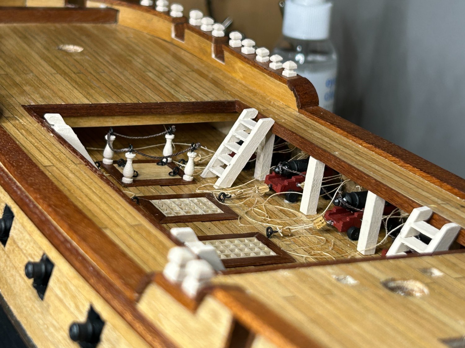
I have made progress on the mid-ships section of the deck, including mounting the ships boats and adding the railings. The boats that came with the kit were metal castings that required the addition of some planks for the floors and the seats. I considered trying to scratch build something more interesting. I got some great info from one of the users on the forum, but in the end I do not think that my skills are quite up to scratch building the boat at this time. I completed the kit provided boats for now. I know these are nothing special, but I didn't glue them in place. They are held only by the line tying them down. If I ever decide to attempt the build something more interesting, these can be removed and replaced pretty easily.


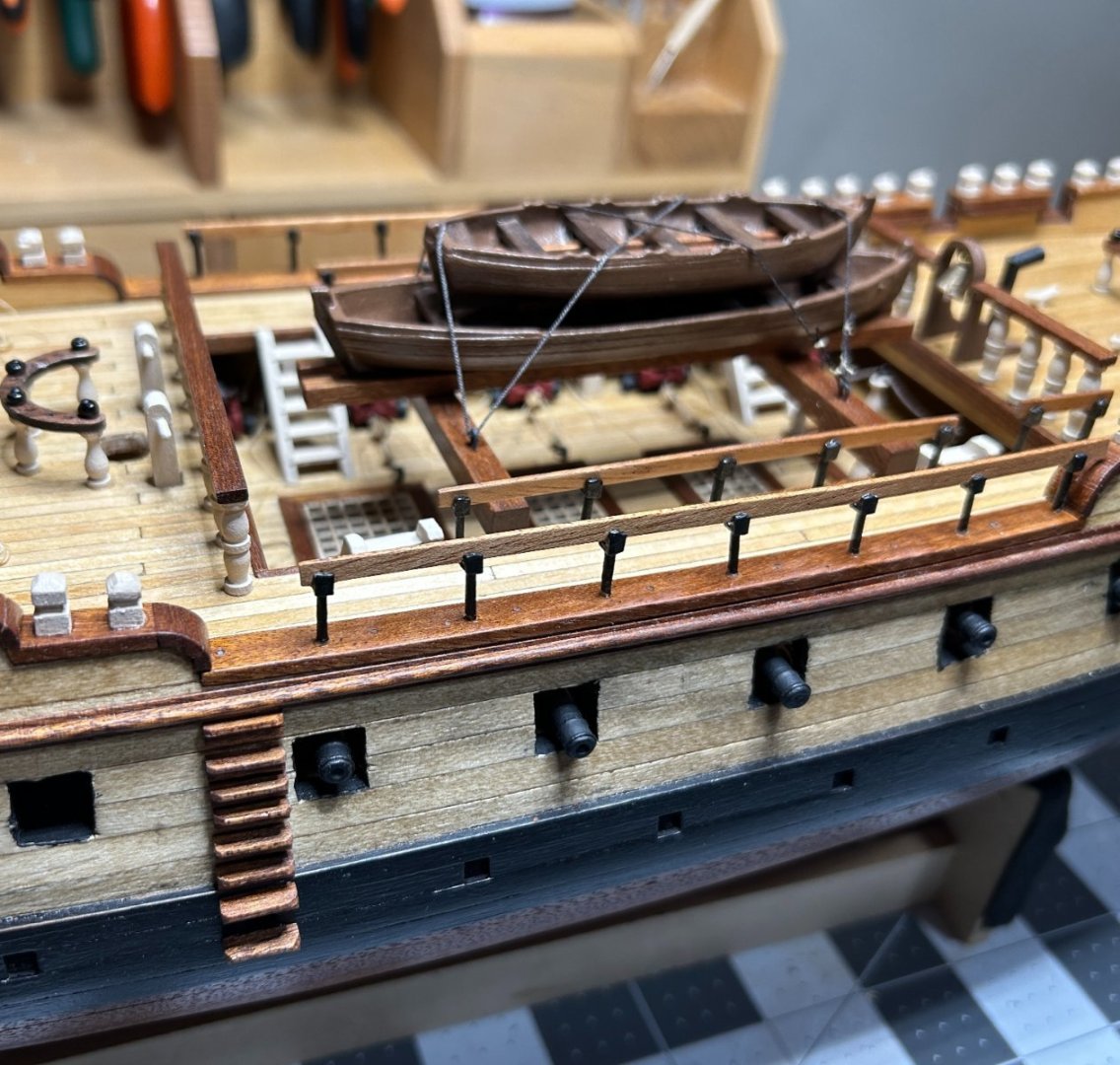
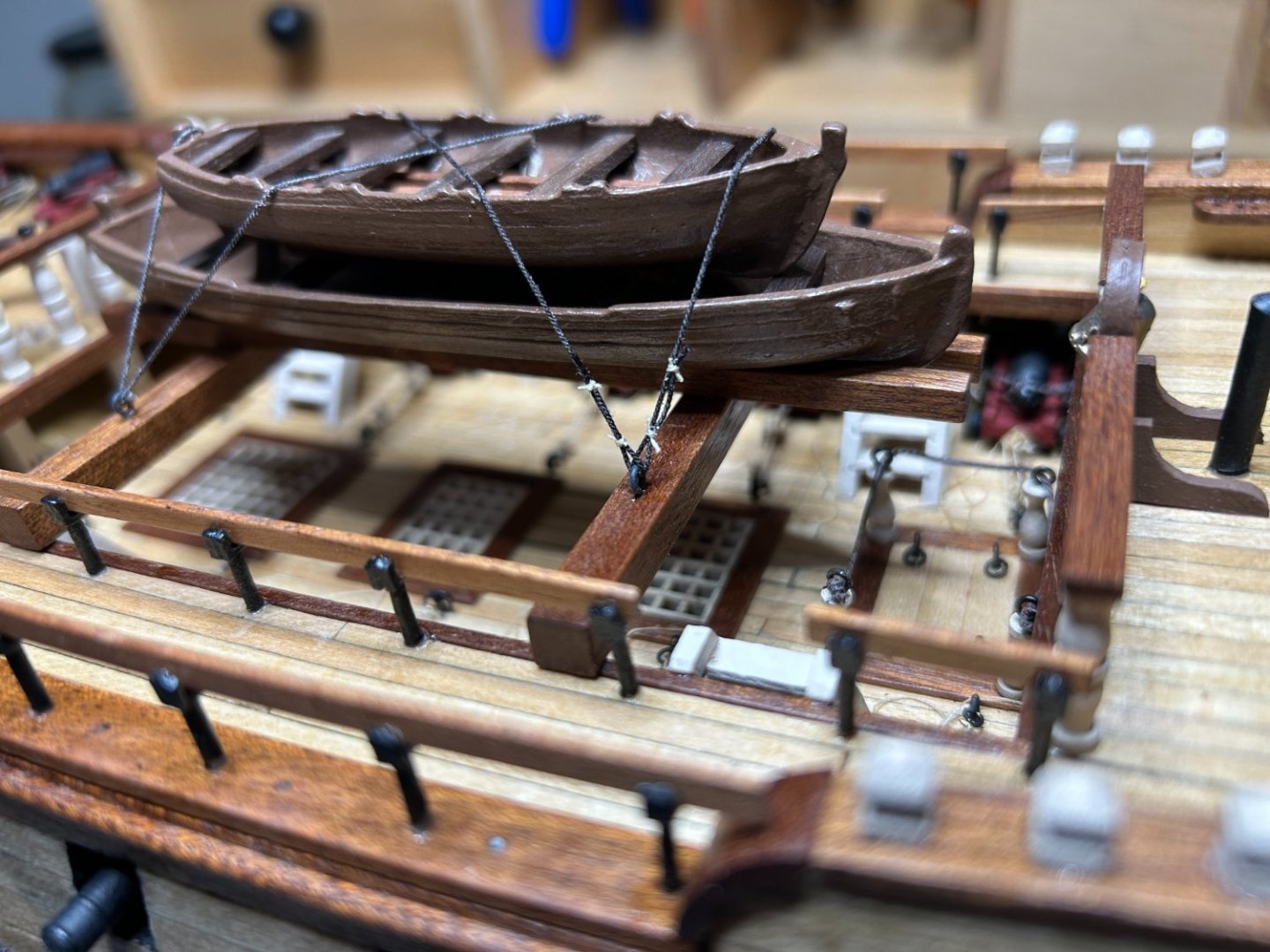

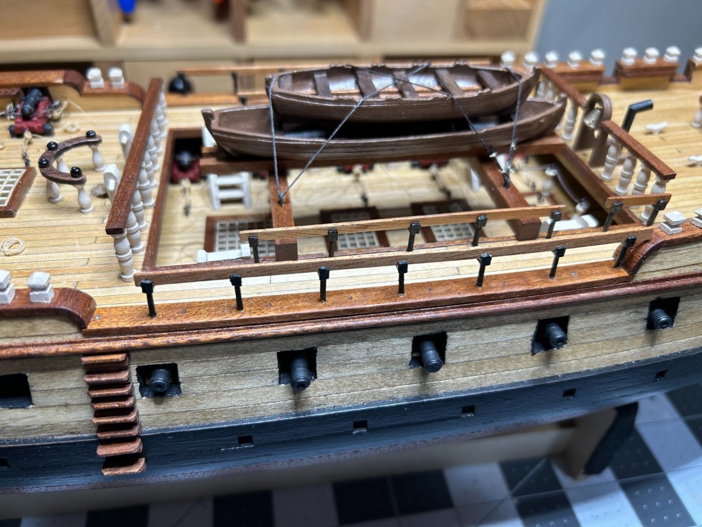
The kit provided 1mm x 4mm strips for the railings. The material was a little too thin to fit snugly in the stanchion and at 4mm it looked too tall. I bought a couple of 1/8 x 1/16 strips at a hobby shop to replace the 1mm x 4mm strips and I needed to sand the 1/16 dimension down a little to get it to fit in the stanchion, but I am really happy with the result
I have a few more items to add to the deck and then it is on to the bowsprit. I have already started fabricating some of the pieces. Starting to think about the deadeyes and chain plate also.
-
I haven’t used that brand. I have had good luck with the “Folk Art” brand available at a lot of the big box craft stores. Not very expensive. Most of the big box stores have store brand that is the least expensive and I have had bad luck getting good coverage with those. Are you using any sort of primer or sealer? I have good luck with a coat of shellac before painting.
-
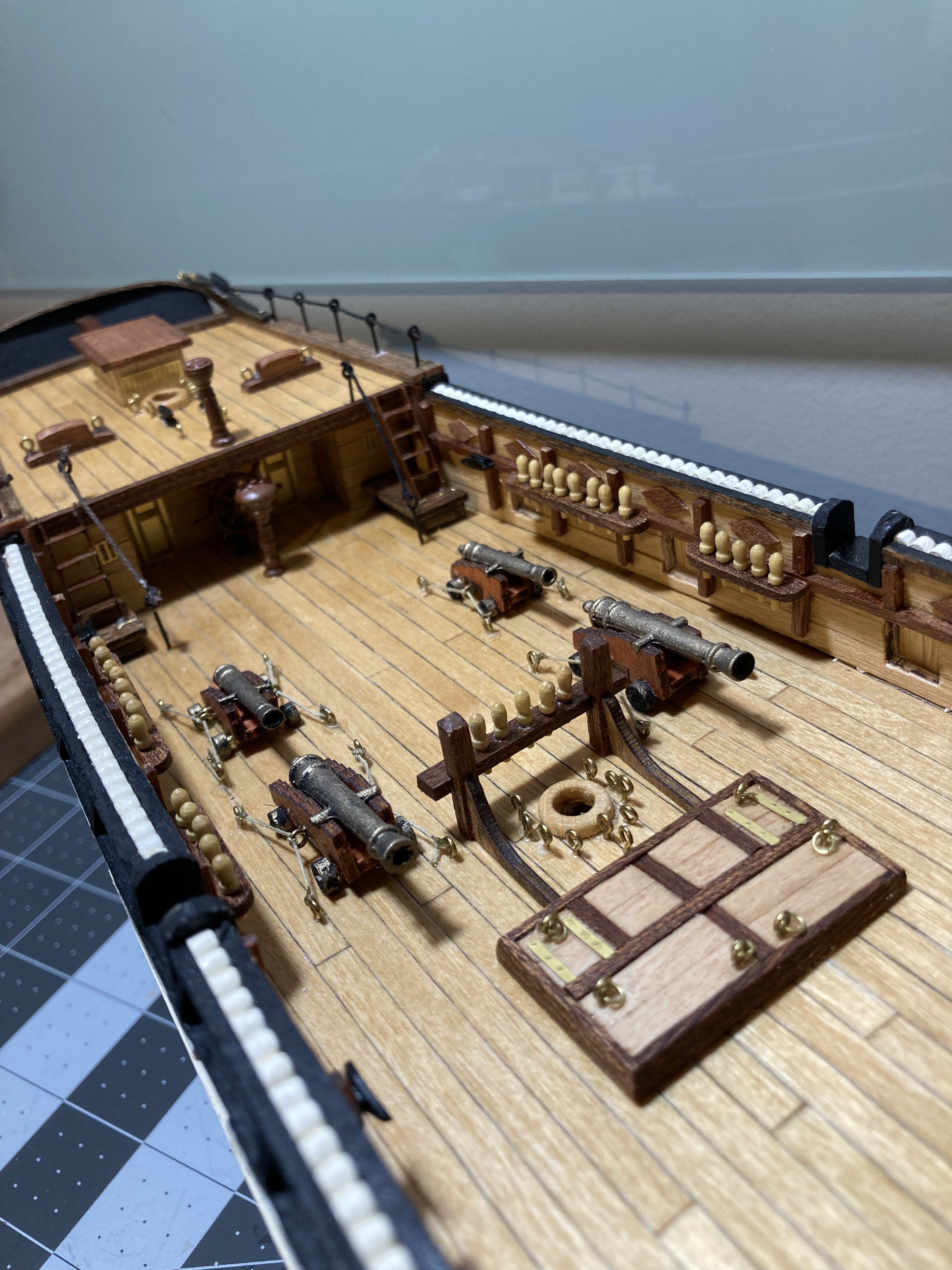
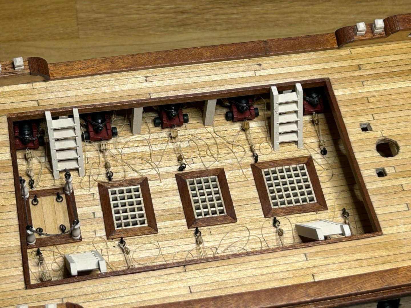
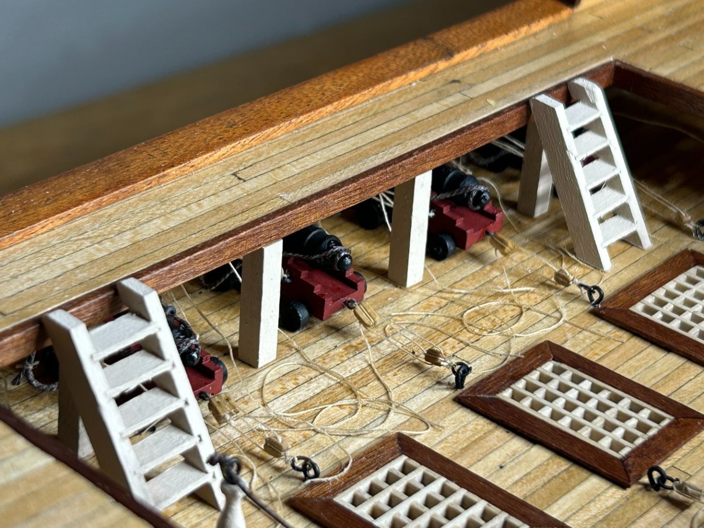
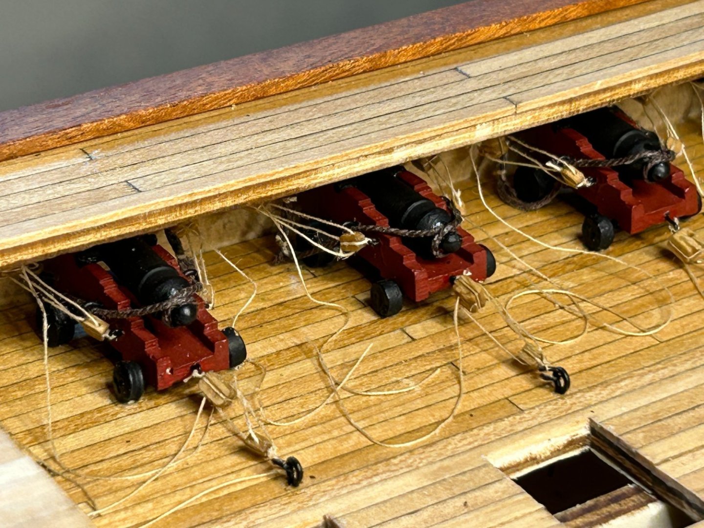
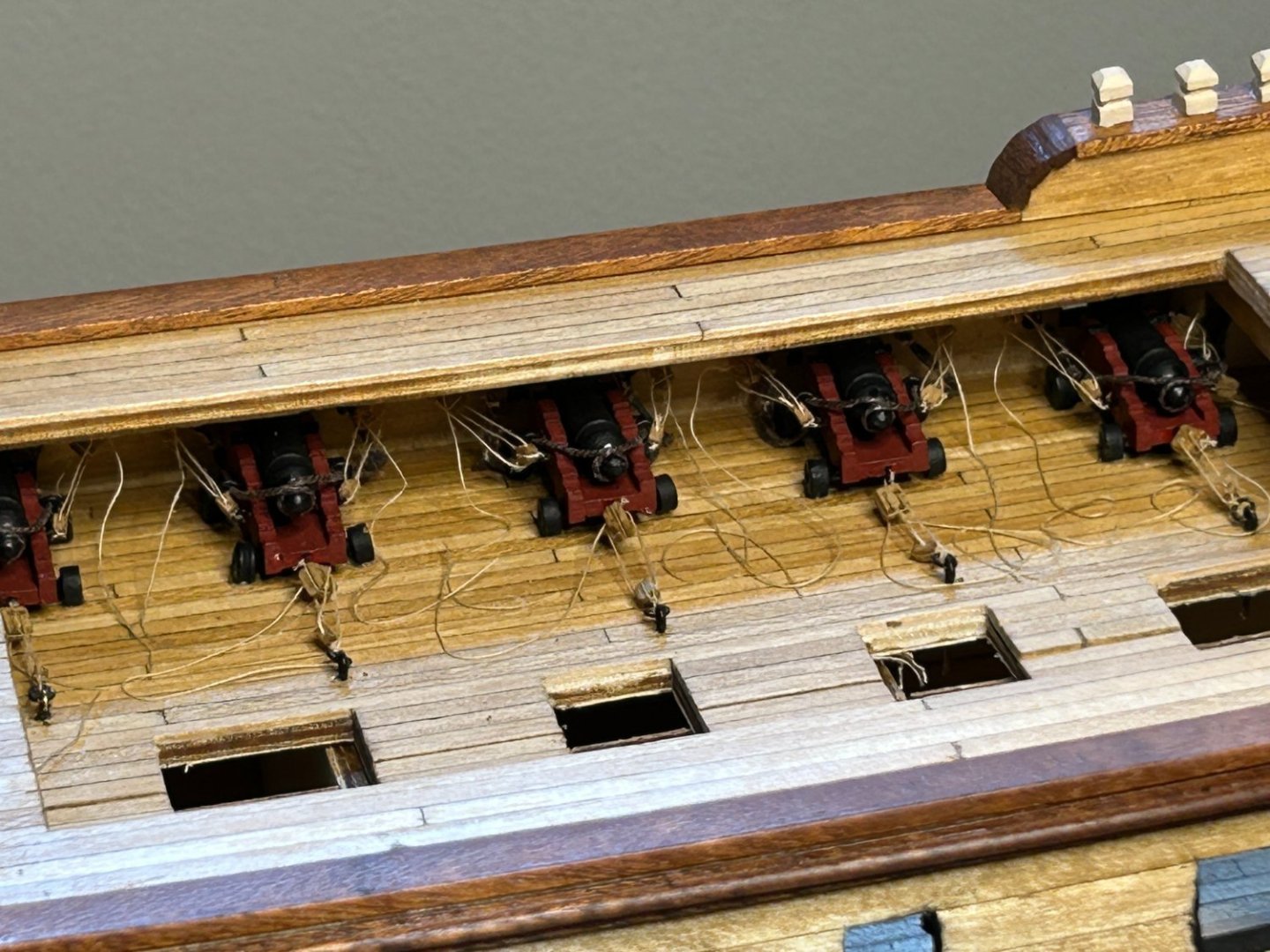
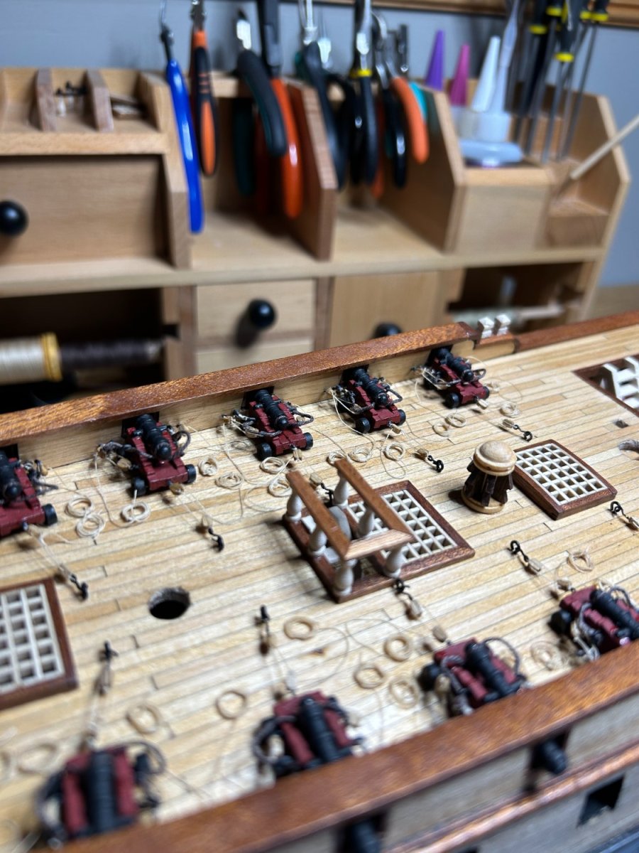
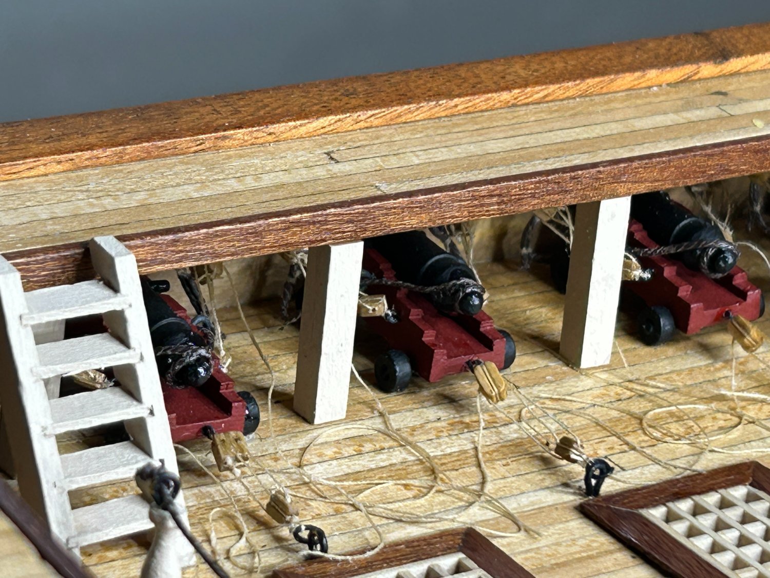
It took me awhile, but I finally have the 12 - 6 pound guns rigged and installed. I have some of the other features of the quarter deck installed, but not everything including the ships wheel. I rigged all of the guns, because one of my goals was to try new things. I don't know if I would recommend it on a 1:85 scale, but I am glad I did.

I will be finishing the quarter deck over the next few weeks, but I will also be working on mounting the ships boats over the opening on the upper deck and I have already started fabricating the components of the bow sprit. I will post updates on those items as I finish them.
Thanks to everyone that has liked and commented on my build log. I appreciate all the support.
-
-
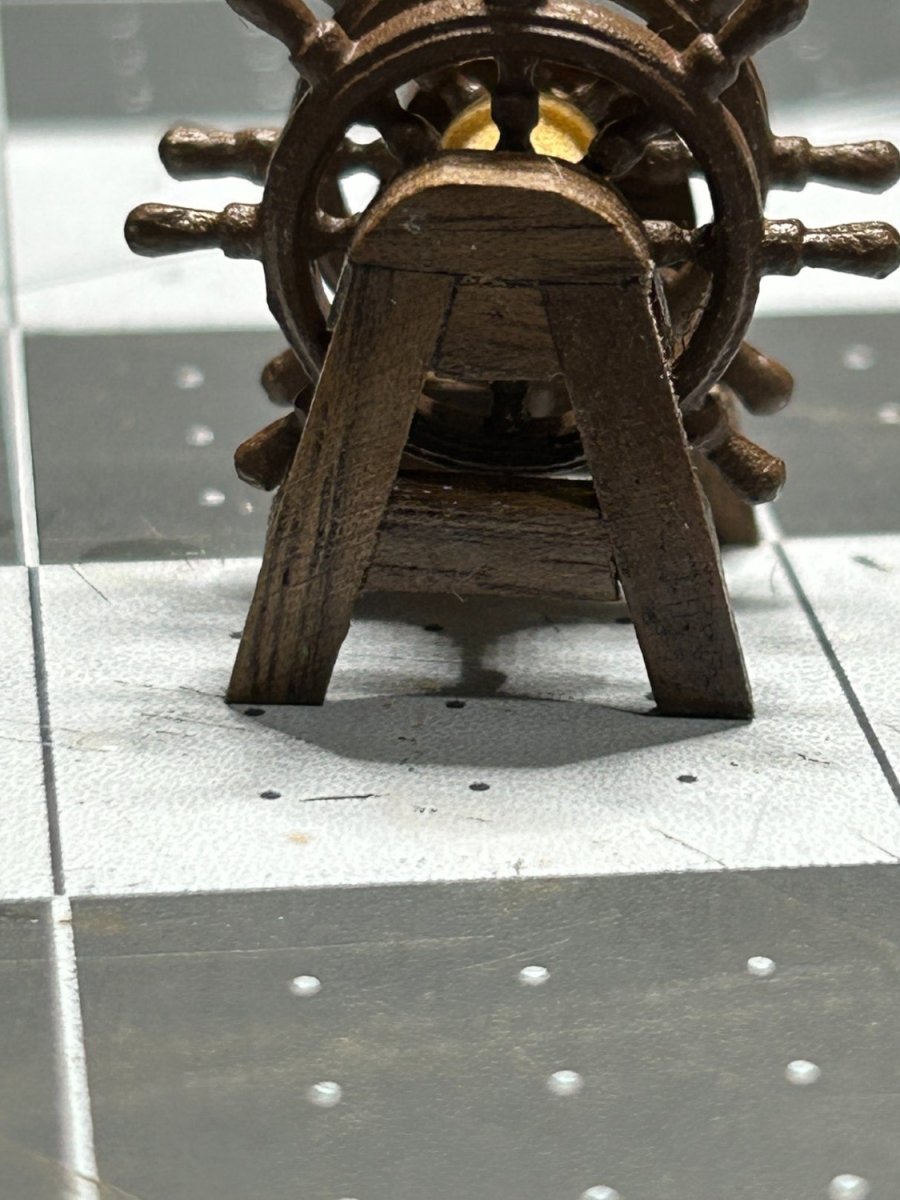
I have been making progress on rigging and installing the 12 - 6 pound guns that are on the upper gun deck. I will get some pictures of that posted in a few days when I am finished with them. I have also started putting together some of the other deck features on the aft part of the ship such as the ship's wheel. I didn't care for the cast metal pieces that were provided with the kit that the wheels were mounted to. I decided to fabricate my own out of some scraps of walnut that I had.I built wooden frames that were the same shape and size of the parts provided by Occre. This is what I came up with and I am pretty happy with the result.
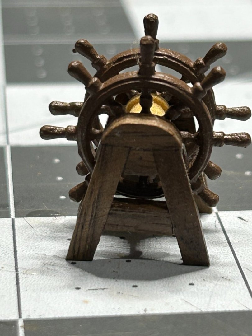
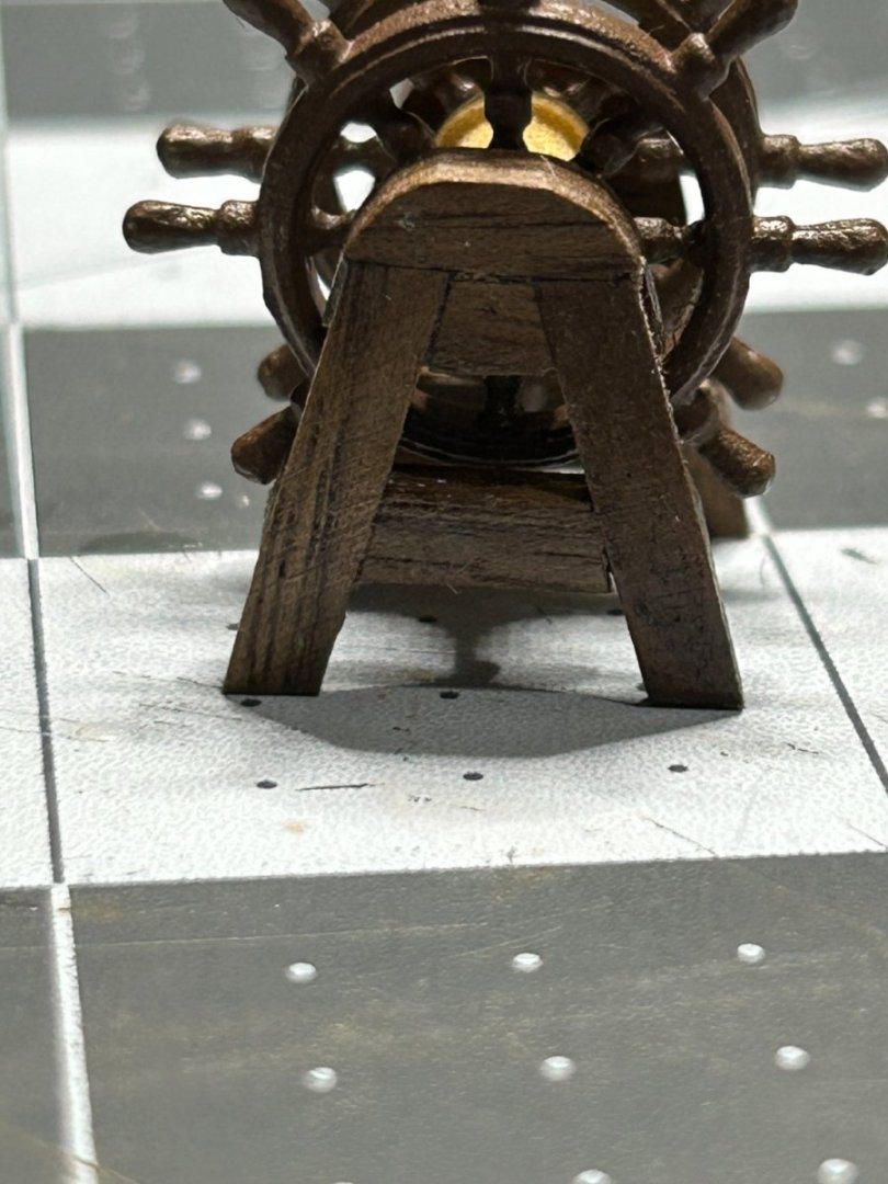
The picture on the right shows my version next to the part supplied by Occre.
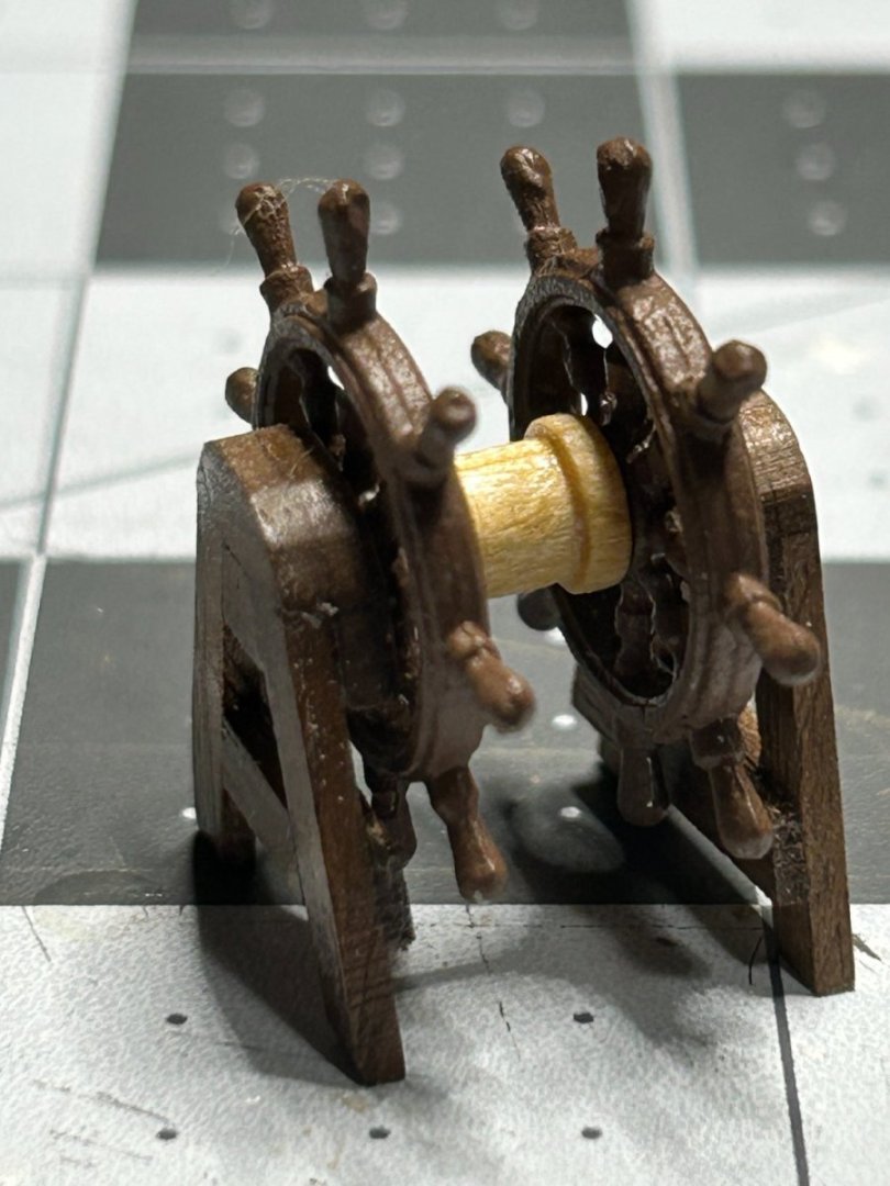
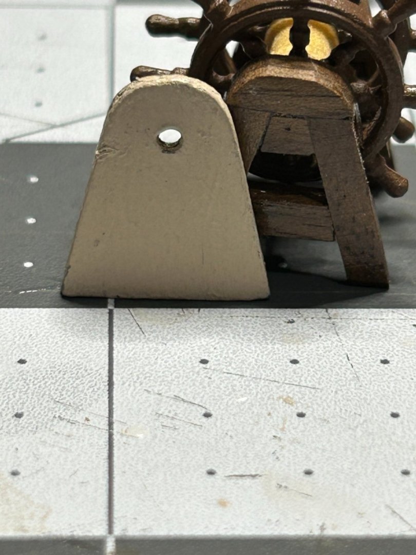
Now the problem - after putting this together and setting it on the deck, it looked way too big. The wheel measures 24mm in diameter. A 1:85 scale that works out to a diameter 7.5 feet. Add another few mm for the frame and the total height is close to 8 feet tall. I looked online at a few modern photos of ships and I can't find any that appear to have a wheel even close to that big.
If anyone has any information to suggest that these aren't way to big, please share it with me, but I really think I am going to have to purchase some smaller wheels and start over. I found some online that are 14mm that should be closer to a 4 foot diameter.
I am a little bummed because I liked how these turned out.
-
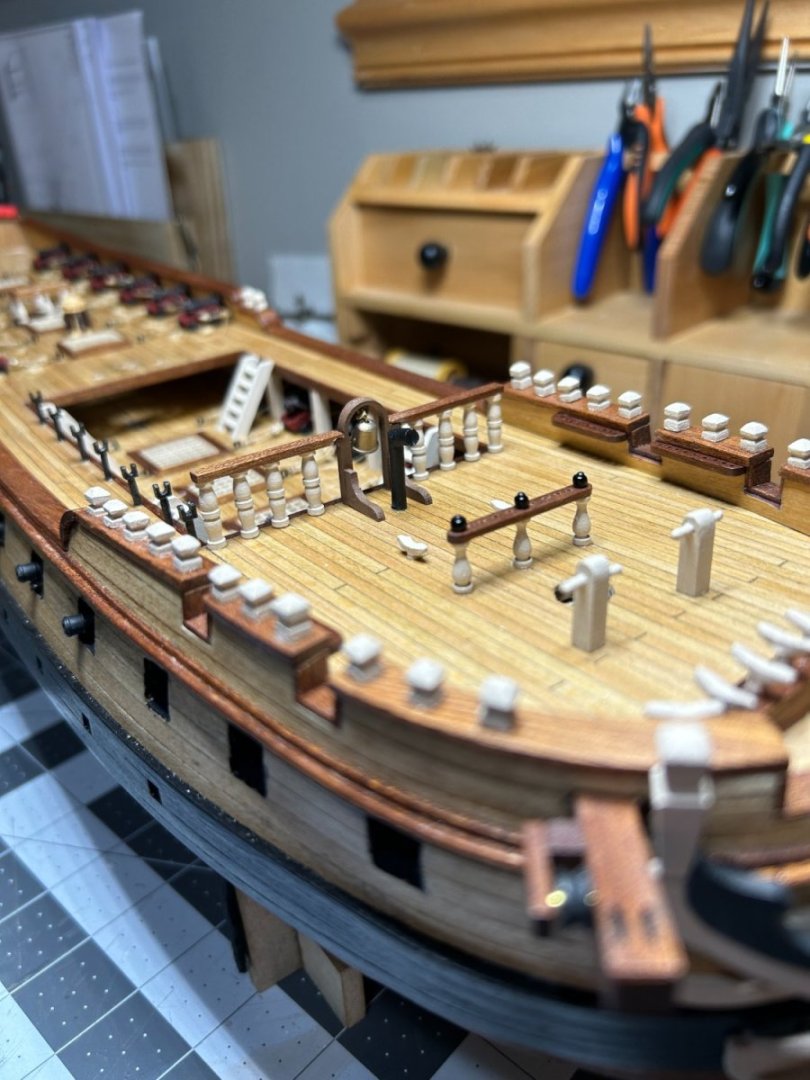
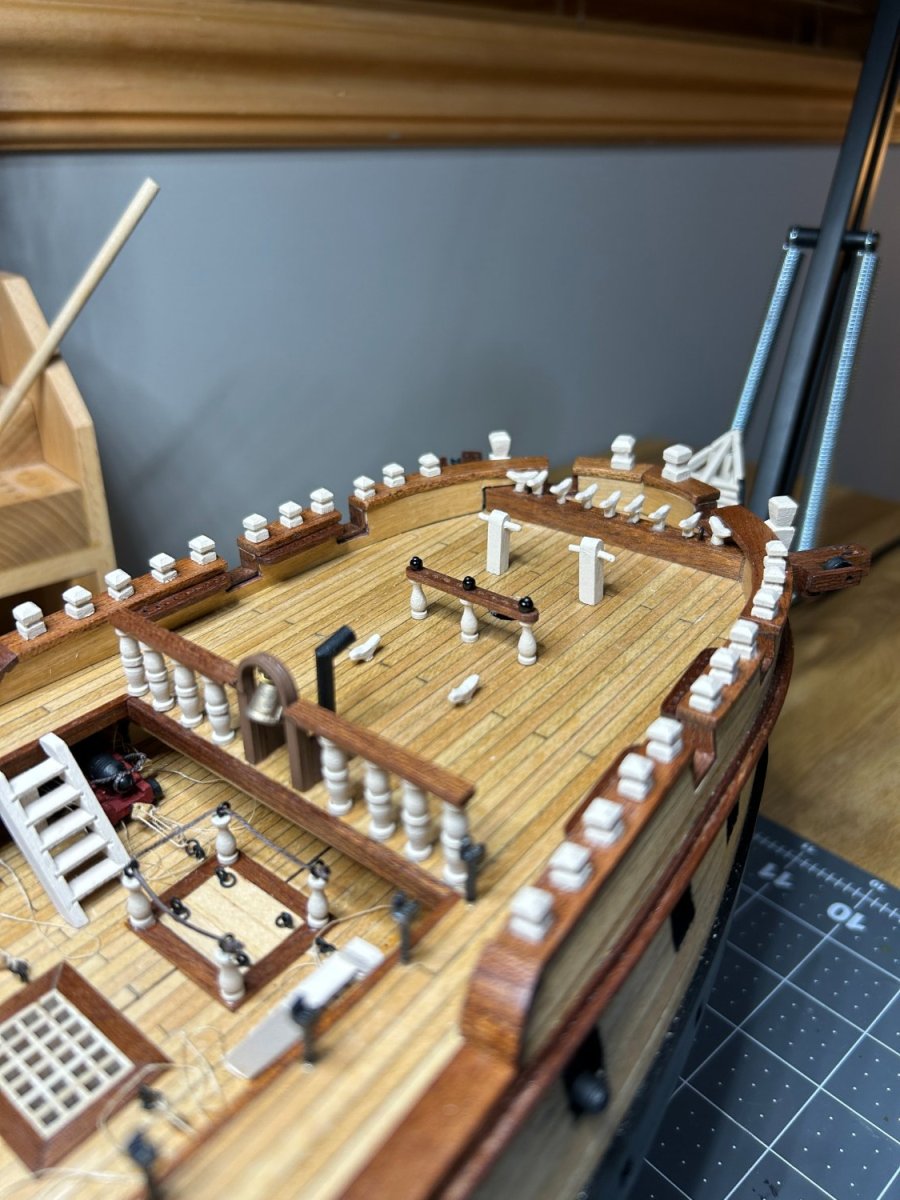
Progress has been a little slow in the shipyard. Summer activities have gotten in the way. I have made some progress adding the deck features on the forward part of the ship.
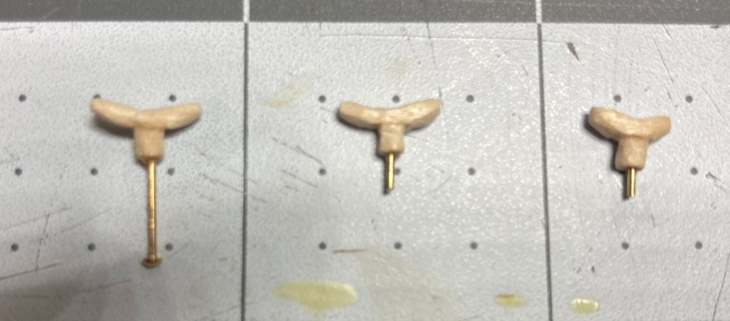
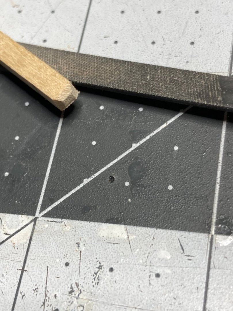
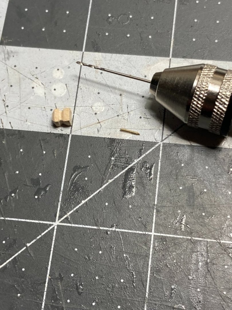
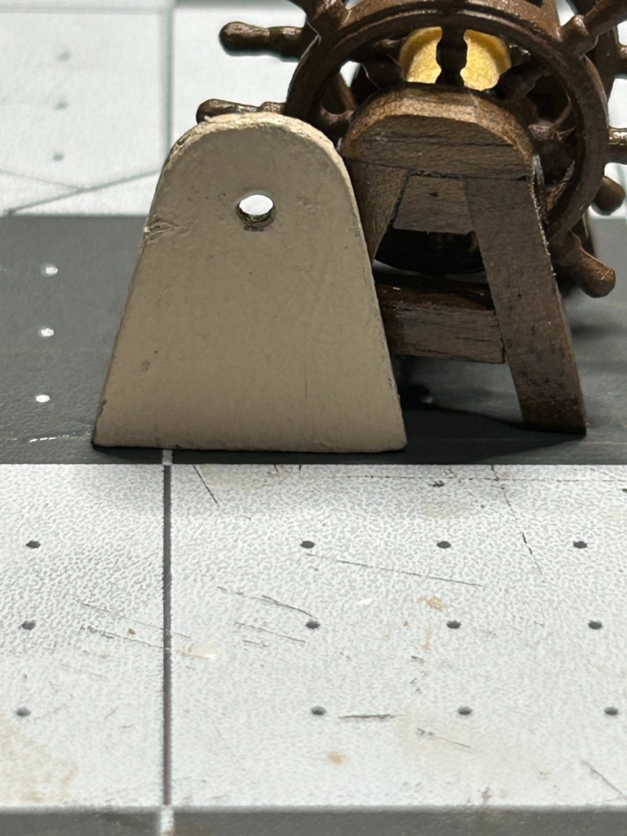
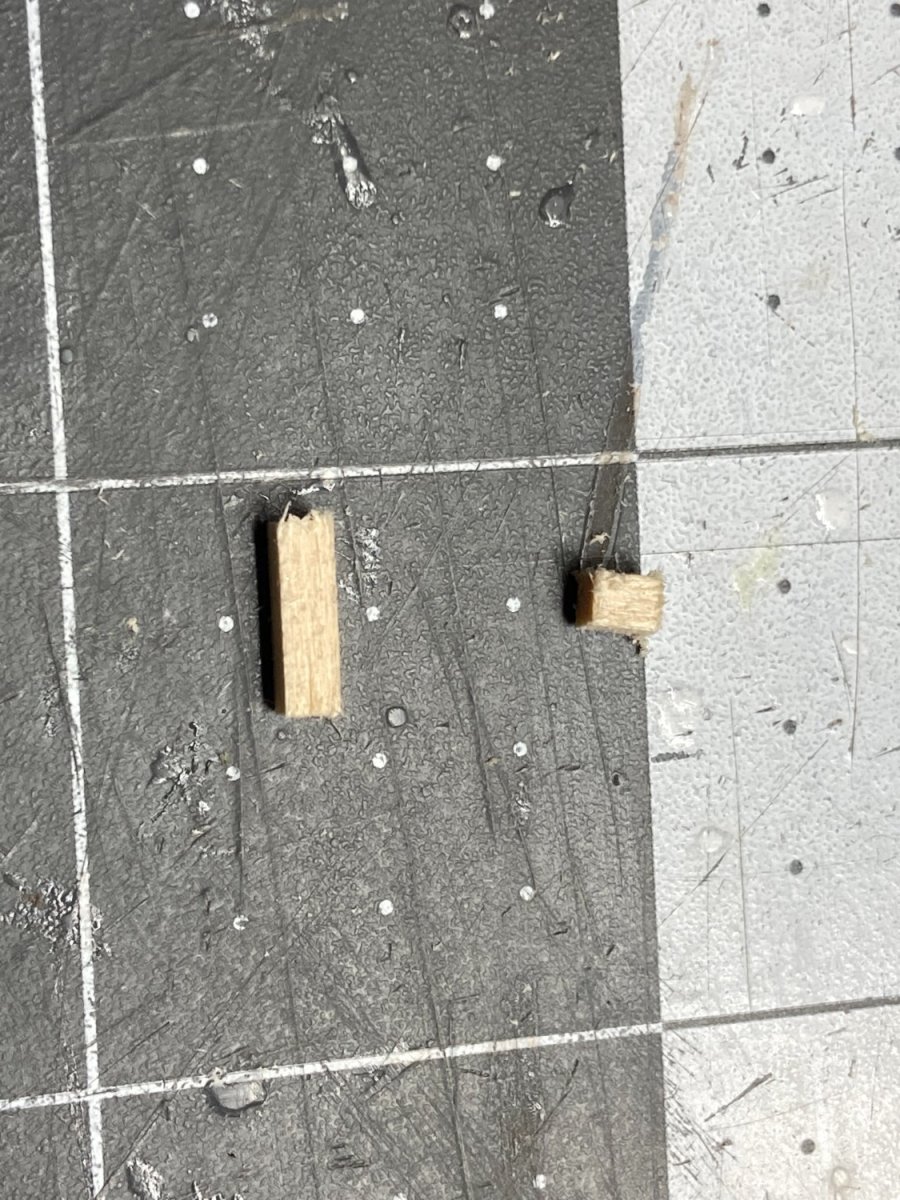
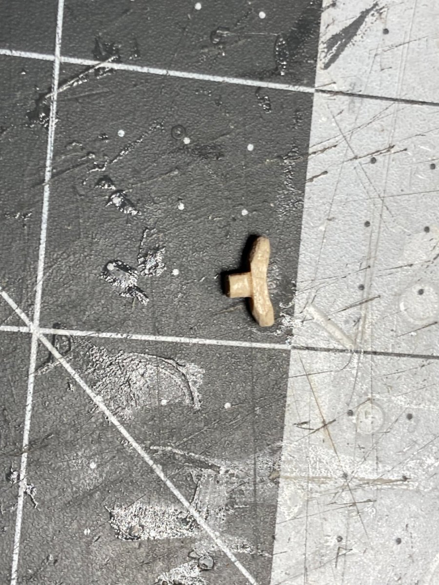
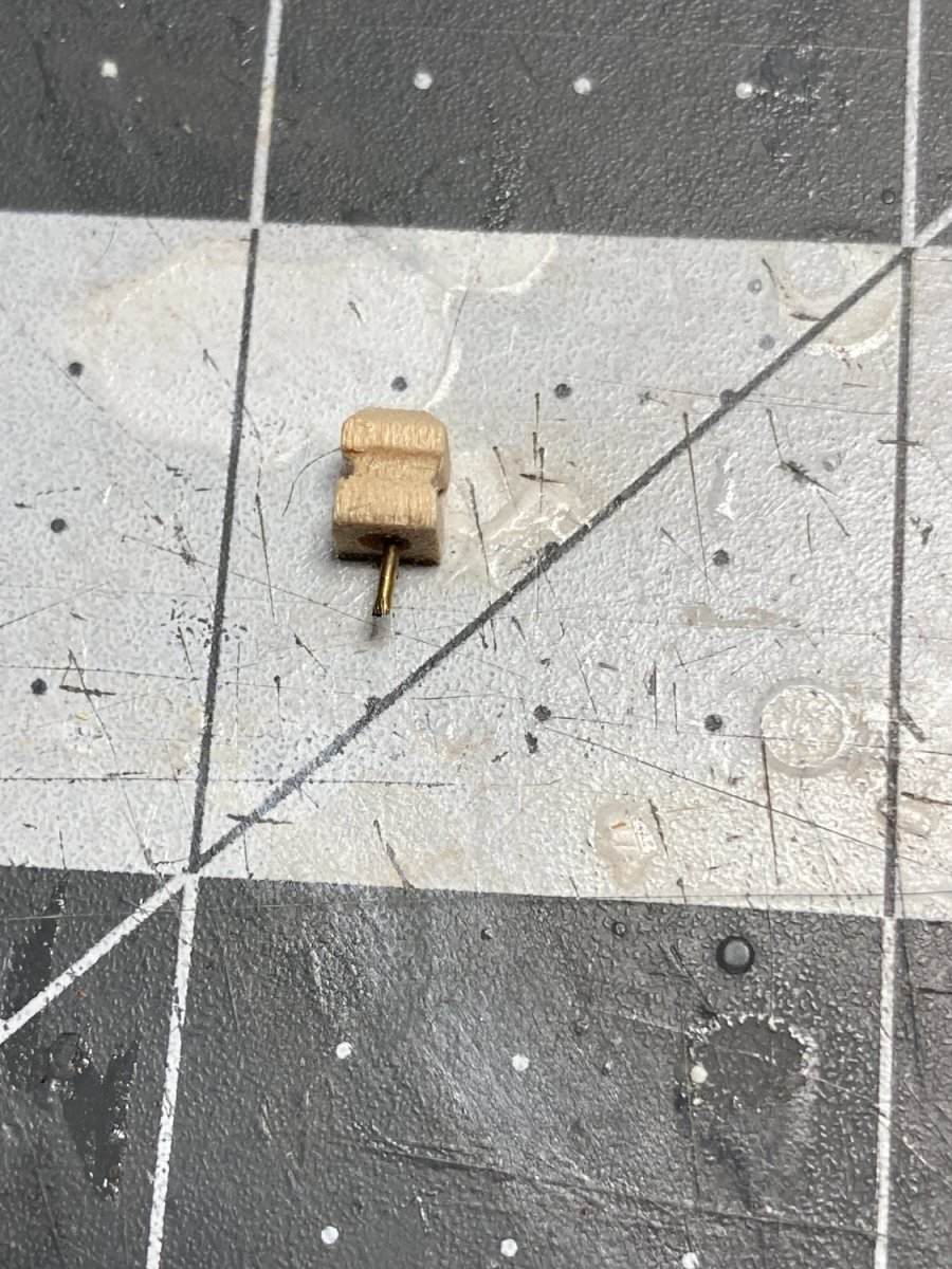
I didn't like the cleats that came with the kit. They were mounted flush with no pin, and I didn't trust they would hold effectively without a pin. I decided to take a try at carving my own. I glued a couple of pieces of 1/8 x 1/8 inch basswood together and then shape it with a file.
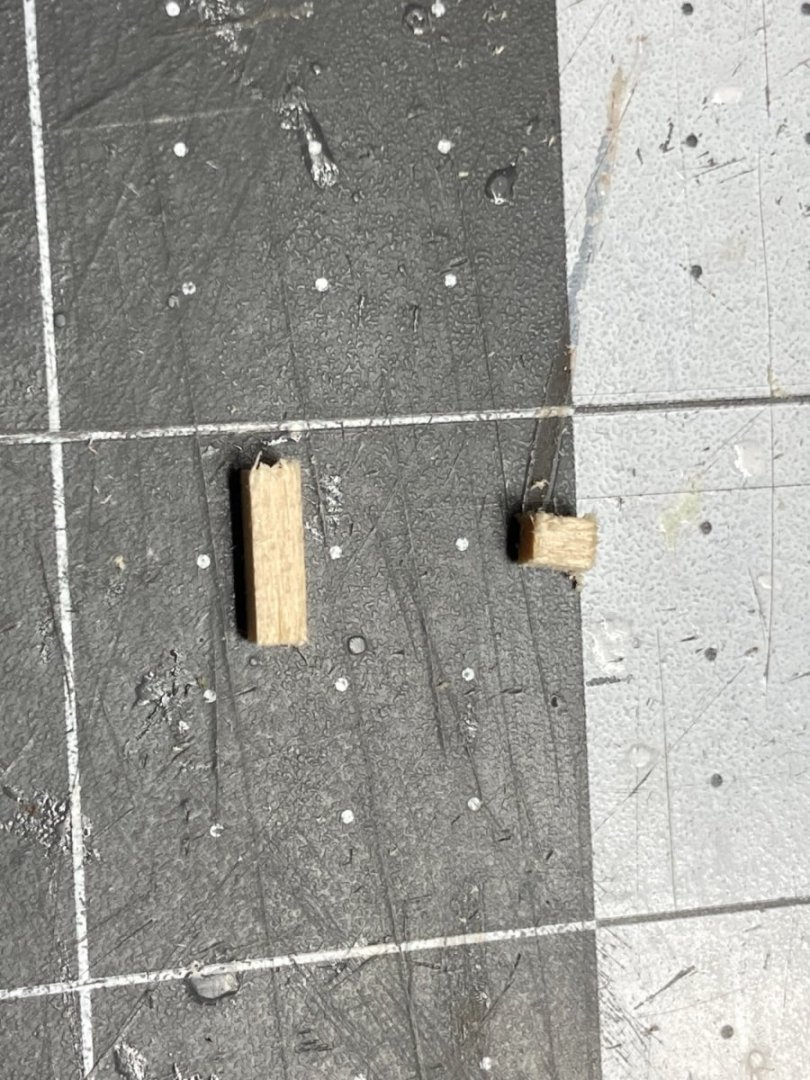

Then added a pin so it could be securely attached.
I added the belfy, a railing the pin rails and some sampsons to complete the forward part of the deck.

-
Nice job on the brass wire. I struggled with that on mine.
-
Your first layer of planking on the hull looks fantastic. I am very impressed for your first ship.
Cutting the deck planks is a good decision. Looks really good.
- Bill Saindon and Mr Whippy
-
 2
2
-
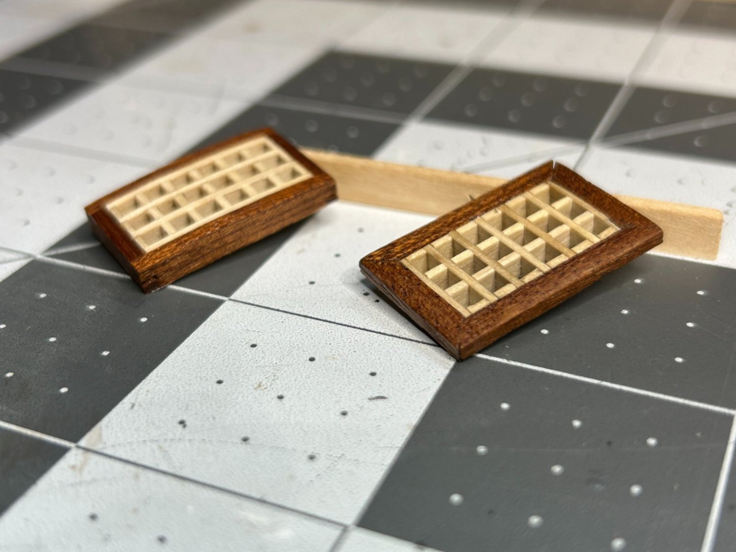
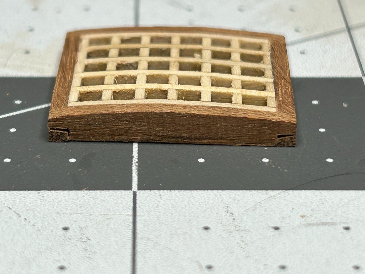
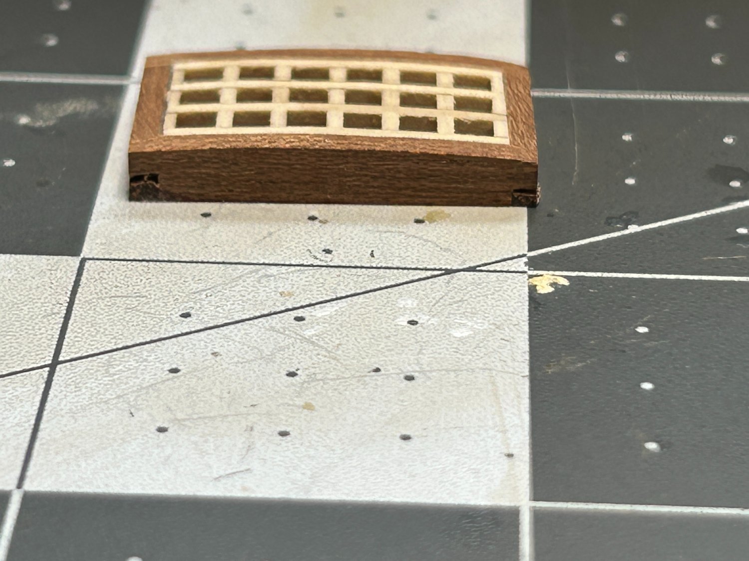
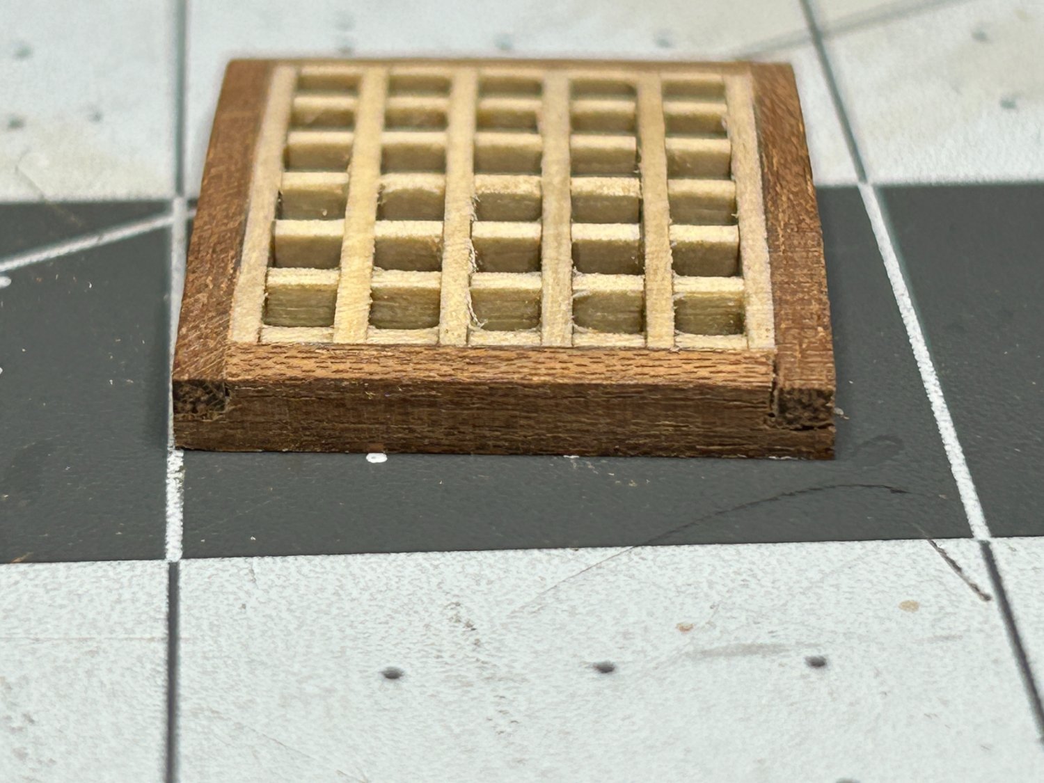
Here is my attempt at making an improved grate for the upper deck of my ship. I used leftover material that came with the kit. The openings of the grate would work out to 6 - 7 inches which is about double the size they should be. I do not think I have the skill or equipment to make my own grating material. I considered purchasing proper scaled materials, but I have already blown the budget on this ship a little bit by buying miniature rope from Syren for most of the rigging.
At work I often tell people not to let perfect stand in the way of better, and that is the way I am looking at this build. The grates are far from perfect but better than the first ones I built. The arched top isn't perfectly symmetrical, but that is the best I could do with the limited left over material. I had a third one that I took way to much material off of when forming the arched top. I think I have the battens running the wrong way also, but had to make some comprises due to the limited material I had left.
These pictures were before I finished the Sapelli with shellac.


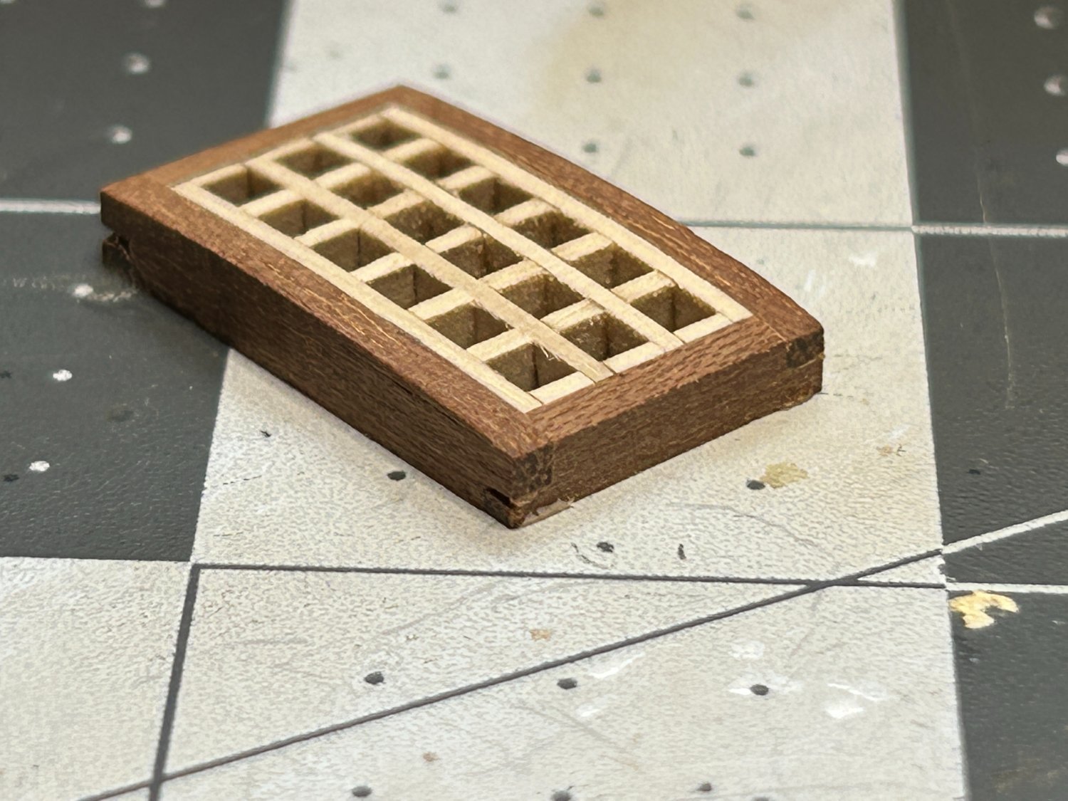
Here is a comparison to the ones built following the instructions.
Thanks to Allen for helping with how to fabricate the head ledge and coamings and the information on the proper scale.
-
I spent some time this weekend expirementing with using card stock. I think I need some that was a little thinker to get a better result, but I think I could get there. I did notice a potential problem with not using the kit supplied parts. before I started with the soldering, I had drilled the holes for pins in the rudder. If I use a 1.2mm card stock strip to make the pintle and place it at the top of the notch in the rudder, it won't cover the pin holes that I have already drilled. If I place them to cover the pin holes, the pintle will be placed in the middle of the notch in the rudder instead of at the top.
I really appreciate all the information and great suggestions, but this may be an improvement that gets added to my next model. I think I will be using the kit supplied materials on this model.
- GrandpaPhil, allanyed and Gregory
-
3
-
Your model is incredible. As big and detailed as it is, 2 years is not very long. Someday I hope this kit will be my retirement gift to myself.
- Mr Whippy and drobinson02199
-
2
-
Do you pin the rudder to the ship? The pintels and gudgeons the only means of holding the rudder in place if I build the model as the manufacturer intended?
-
9 hours ago, allanyed said:
For your scale of 1:85, the straps would be 0.047" (1.2mm) wide
Allen
Thanks for the information. No big surprise but the kit supplied material is over scale. They are about 3.1 mm wide vs 1.2mm. I do not own a drill press, so I am not very confident that I could drill the small holes in 1.2mm material with a hand held drill. I may see if I can get some 2mm brass strips and try with that. It would still be over scale, but at least closer.
Hopefully someday I will keep adding to my tool arsenal and will own a drill press and can tackle items like this.
-
Thanks. I appreciate the info.
-
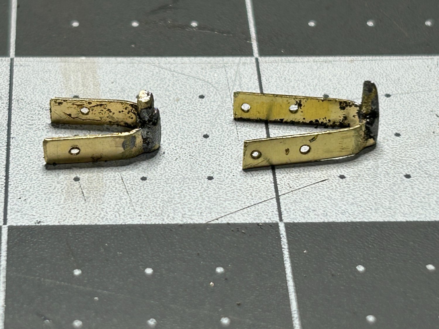
One of my goals with this model is to learn new skills and improve on the ones I developed on my first ship. One of the skills I wanted to learn was soldering. after a few youtube videos and a little bit of practice I made my first attempt to solder parts for the model. I soldered the brass pin into the bracket for the rudder. I know there is a nautical term for the "bracket" but I cannot think of it right now.

They turned out pretty good. There were four total, and I needed to do a little file work to remove some excess solder on a couple. These will be blackened before they are installed.
The next item that will need to be soldered is the lantern for the stern. The is a brass piece that is bent to create a six sided frame for the lantern that needs to be soldered to itself were the two ends meet. My question for the forum is, can the brass part of the lantern be soldered to the cast metal base and top of the the lantern? Not sure if the Britannia Metal has too low of a melting point. Any feedback or advice on this would be appreciated.
- GrandpaPhil and bruce d
-
2
-
Progress has been slow, lots going on this summer outside the shipyard including a few rounds of golf. yesterday I had my best score in over a decade which was a little unexpected. I usually run out of gas after about 14 holes, but on Saturday I managed to keep it together for 18.
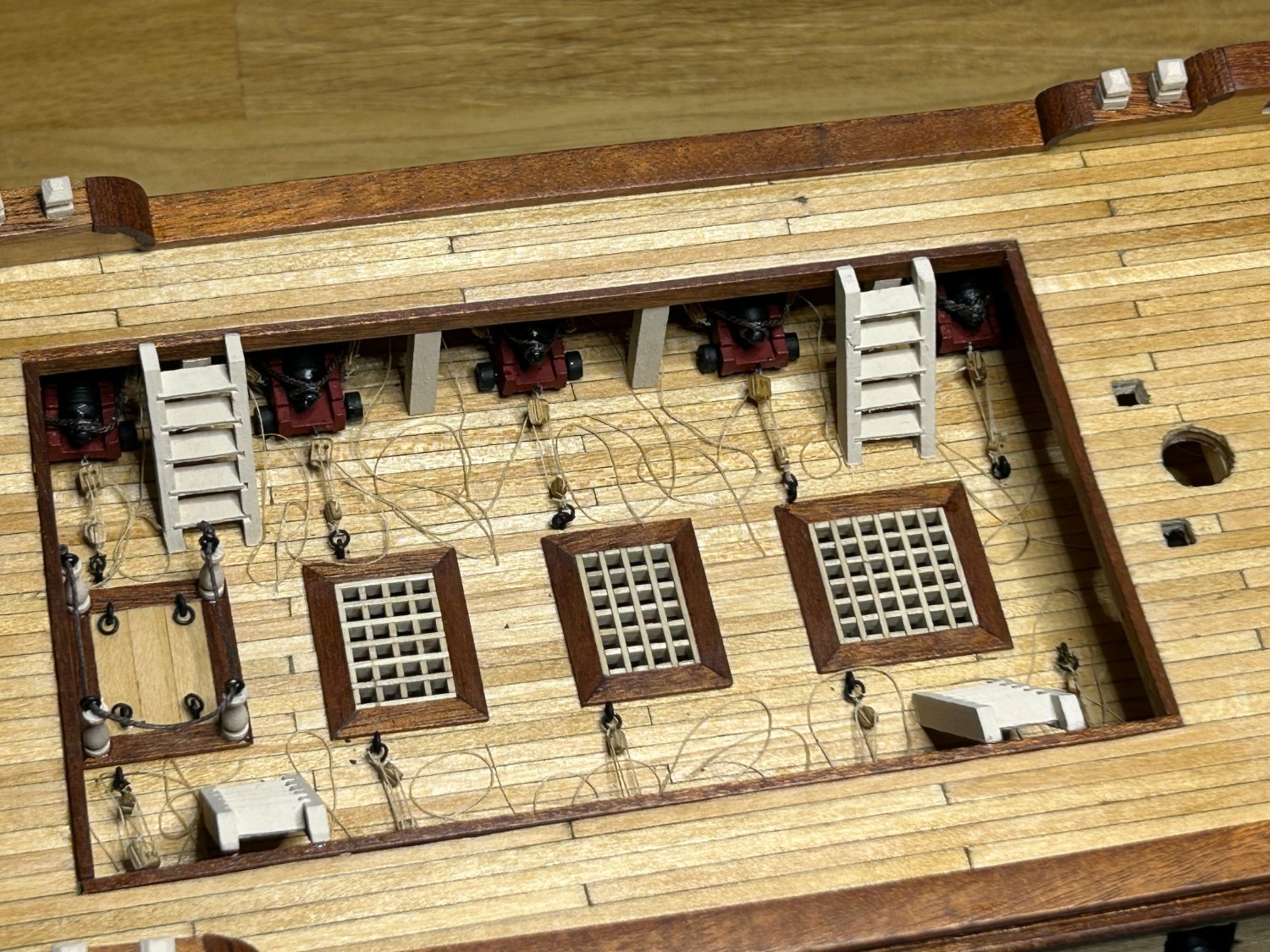
I have managed to finish the lower gun deck. I do need to address the grates that are installed. I started this this project about the same time I discovered the Model Ship World Forum. I sometimes like to finish a few small items before I start the hull and planking, and that took the form of the grates on this model. I built them according to the instructions from Occre with the mitered joints. I soon learned on the forum that mitered joints is not the authentic way to build these.
I have enough material left to attempt to build the grates on the upper deck the correct way, and that is my intention, but I decided to leave the lower deck grates as is. These will be difficult to see on the final model as the ships boats will be mounted above the opening in the upper deck. That argument probably works against my decision to rig the cannons, but that was more about the experience of doing it that the visual that will be difficult to see.


- Patrick B, GrandpaPhil, KurtH and 3 others
-
6
-
I did on my first attempt at rigging cannons recently, but I haven't on the masts.
- mtaylor and Keith Black
-
2
-
I have had similar experience. Even if you break or ruin an item by accident they will send a new one.
- JohnLea, mtdoramike, mtaylor and 2 others
-
5
-
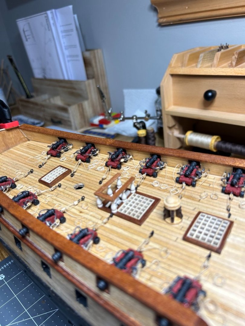
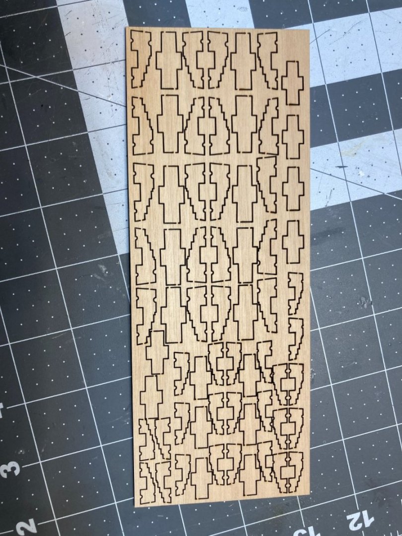
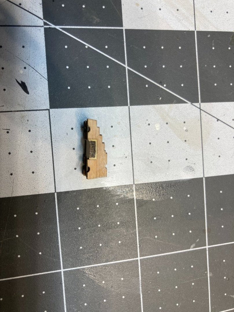
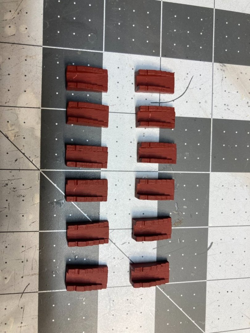
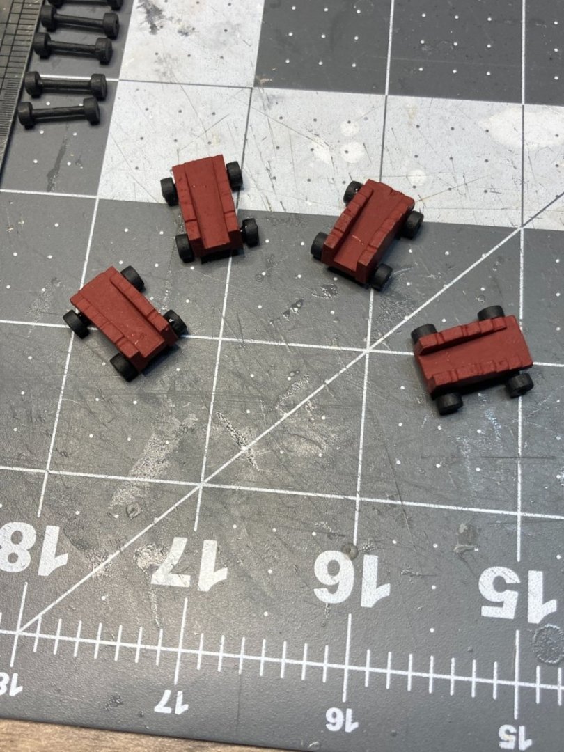
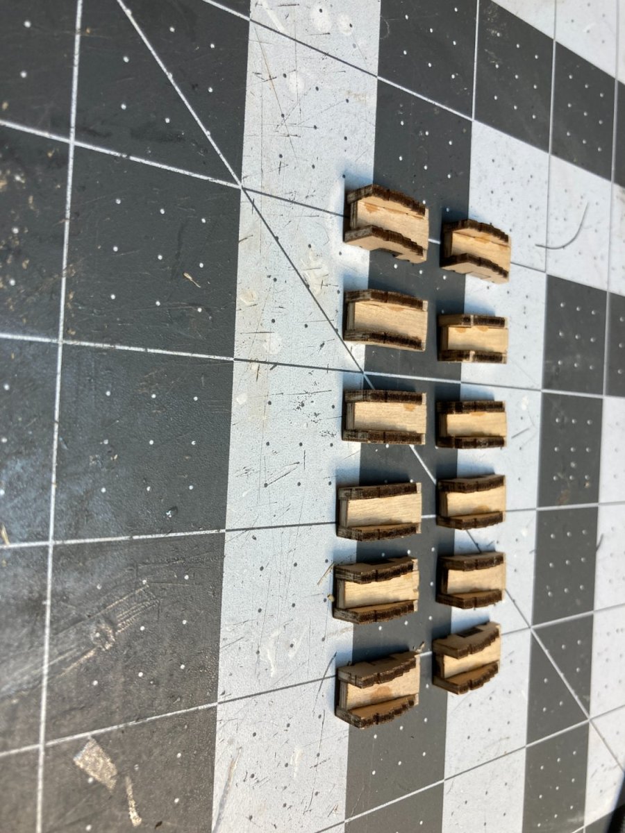
I still need to do the touch up work on the head, but I decided to take a break from the head and start work on the 12 pound guns for the lower gun deck. The kit has ten 12 pounders that are complete with a gun carriage, and I think 14 false barrels for the rest of the gun ports on the lower gun deck. First step was to assemble the carriages from the laser cut sheet. I assembled the 12 and 6 pounders that go on the upper gun deck.
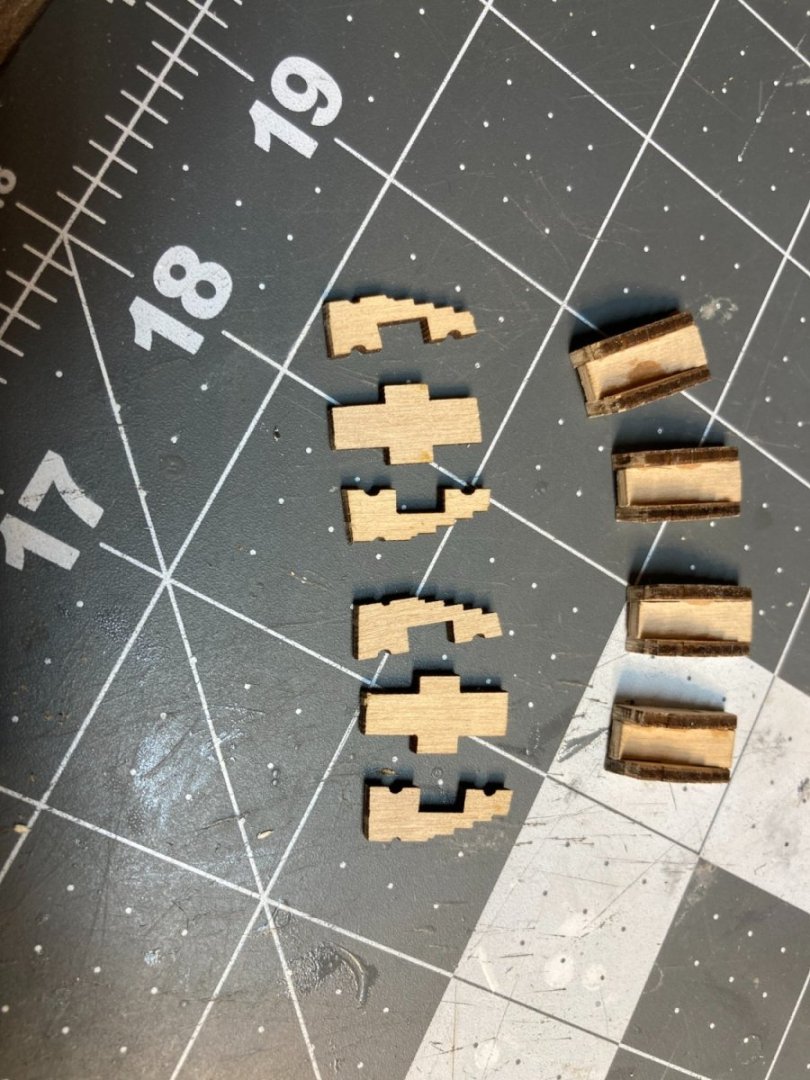

I filled in the gaps with some filler and then painted the carriages a dark red.
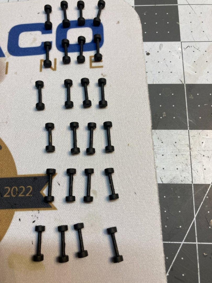
Next up was building the axles. There were two sizes of wheels. I assumed that the smaller wheels were all for the 6 pound carriages and the bigger wheels for the twelve pounders. I assembled all of the smaller wheels on axles that fit on the 6 pound guns only to realize that the smaller wheels were also needed for the rear wheels on the 12 pound carriages. I had to cut the axles apart to get them to fit on the bigger 12 pound carriages.
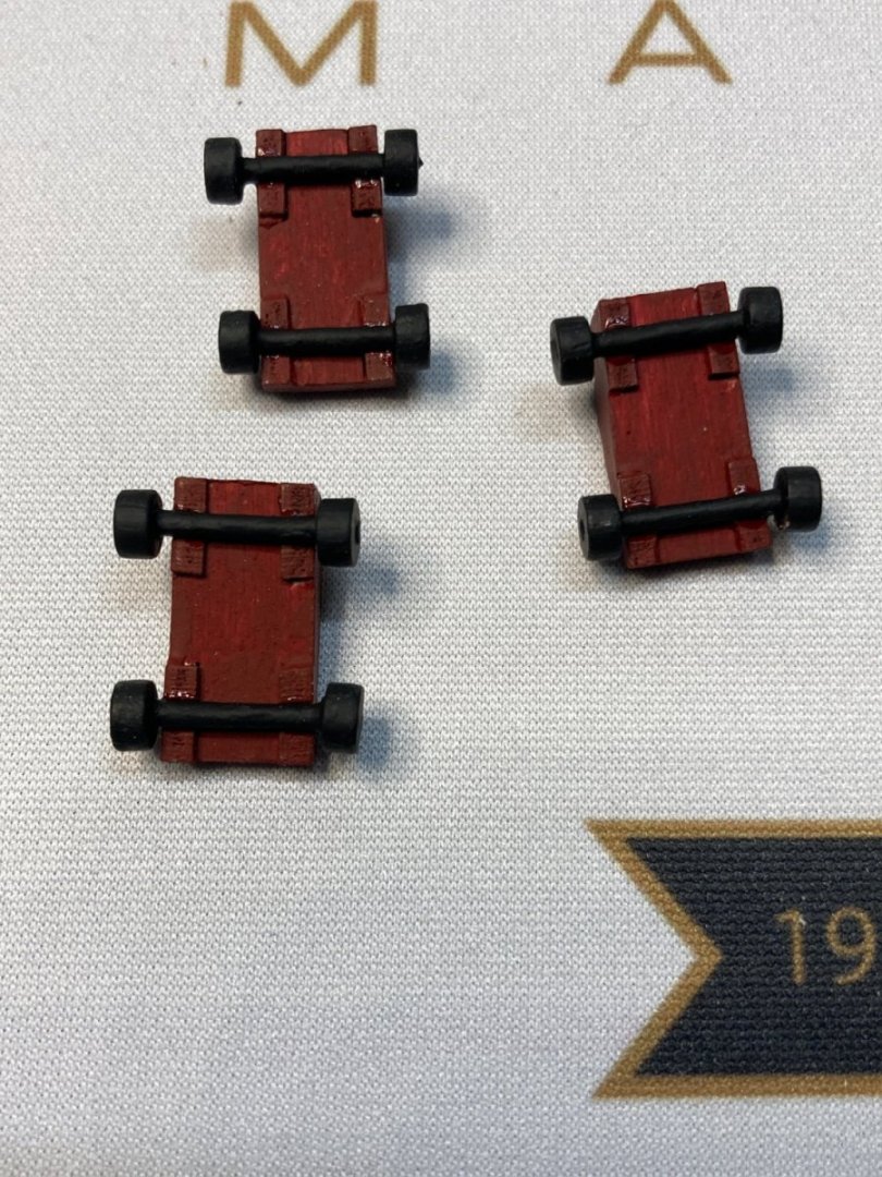
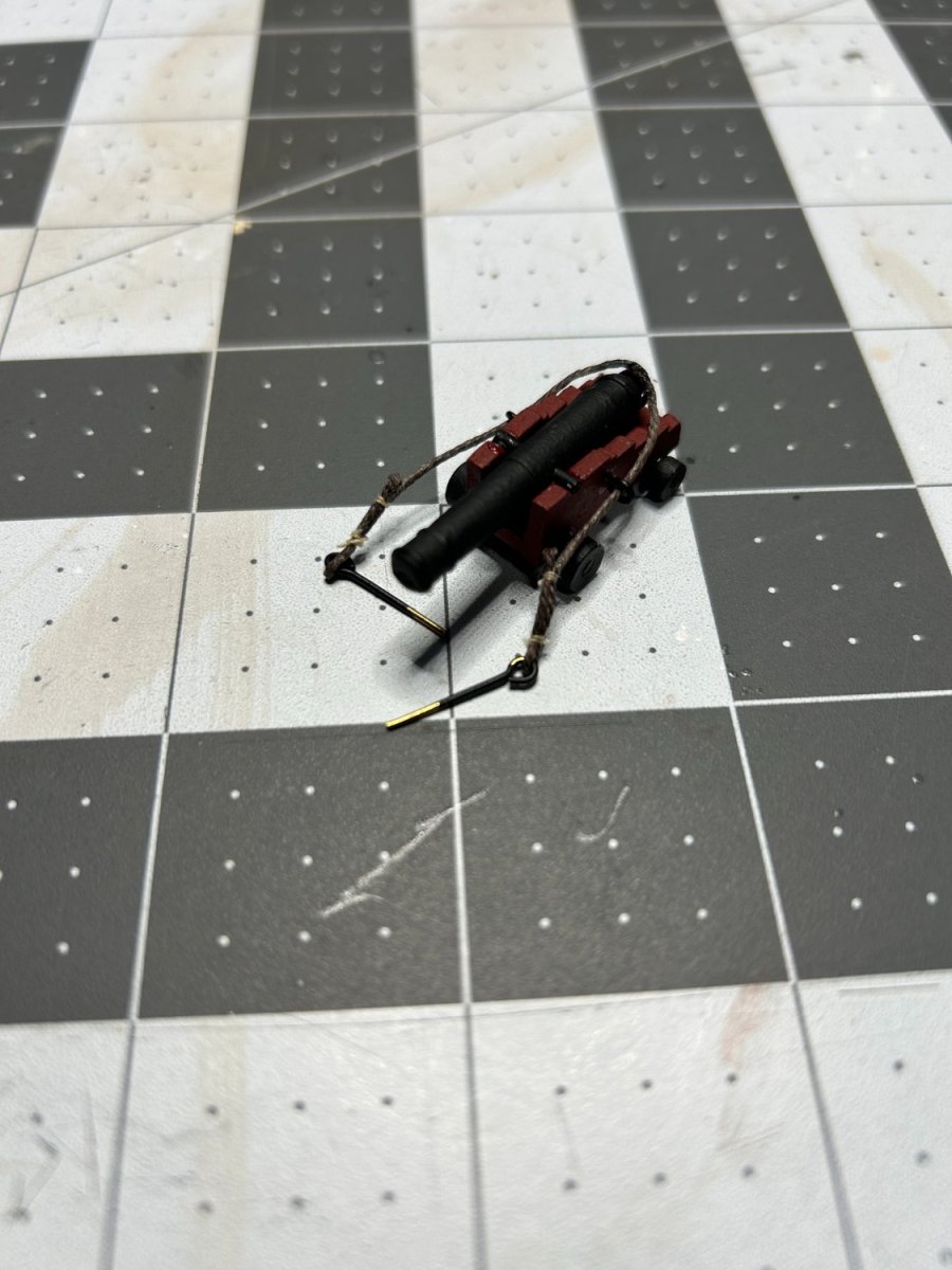
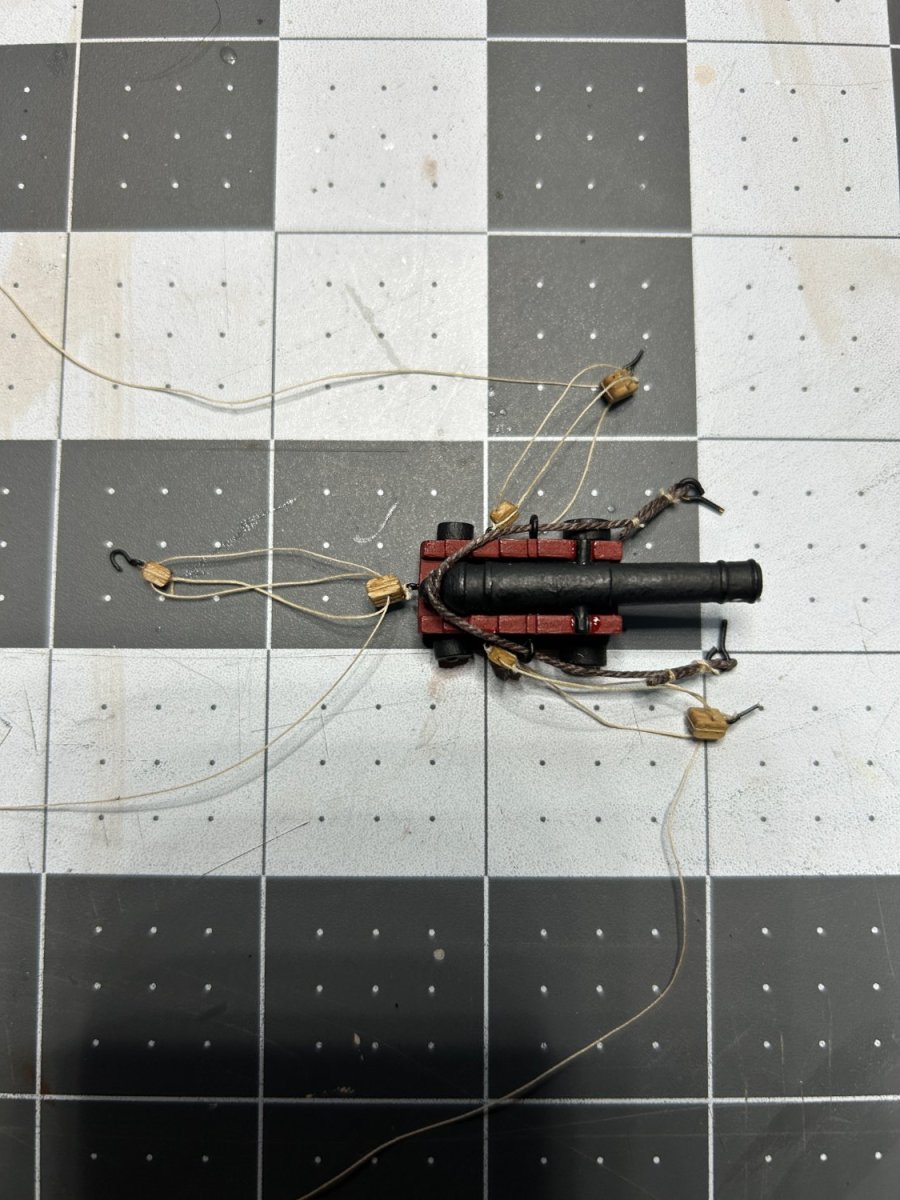
I decided that I wanted to rig the guns. I think a lot of people on the this forum might suggest not doing that on a 1:85 scale model, and they might be right, but with this model I wanted to do things that I didn't do on my first model, so I am going to add the rigging to the guns. You will also notice something odd with one of the wheels on the picture below. I lost one of the wheels and didn't want to wait for a replacement, so I repurposed a leftover deadeye from my HMS Beagle.
.thumb.JPG.1727a76173d1a184b4a3cd13a8f933b4.JPG)
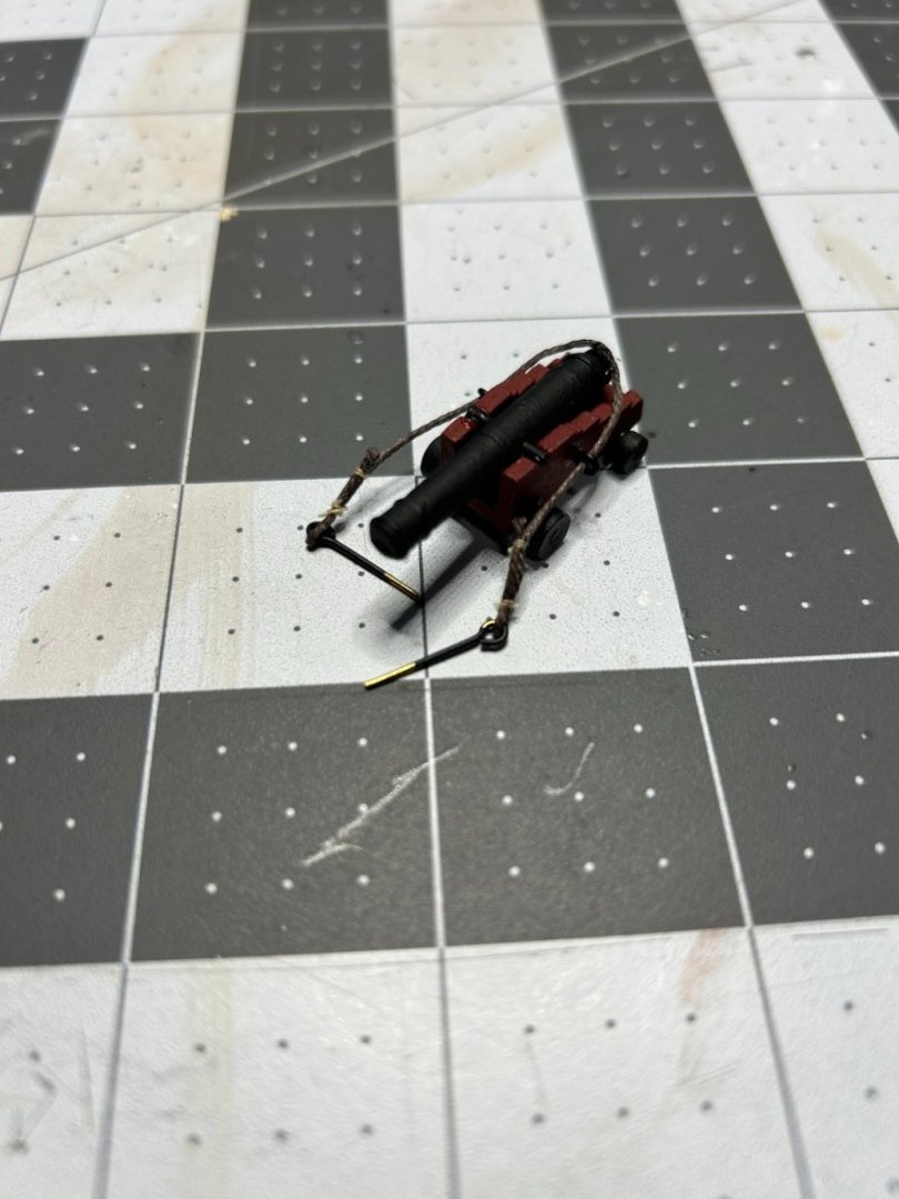

Attaching the blocks to the ship was a real challenge given the deck that overhung the gun deck. I am hoping to rig my ship as it might have looked in action, so I decided to show the lines for the gun tackle laying on the deck as opposed to neatly coiled up. I did have to abandon the hook that attached to block at the rear of the gun to the ring on the deck because the two blocks were too close together with the hook.
- GrandpaPhil, Patrick B, KurtH and 2 others
-
5
-
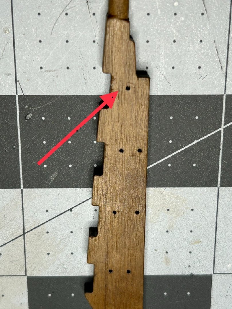
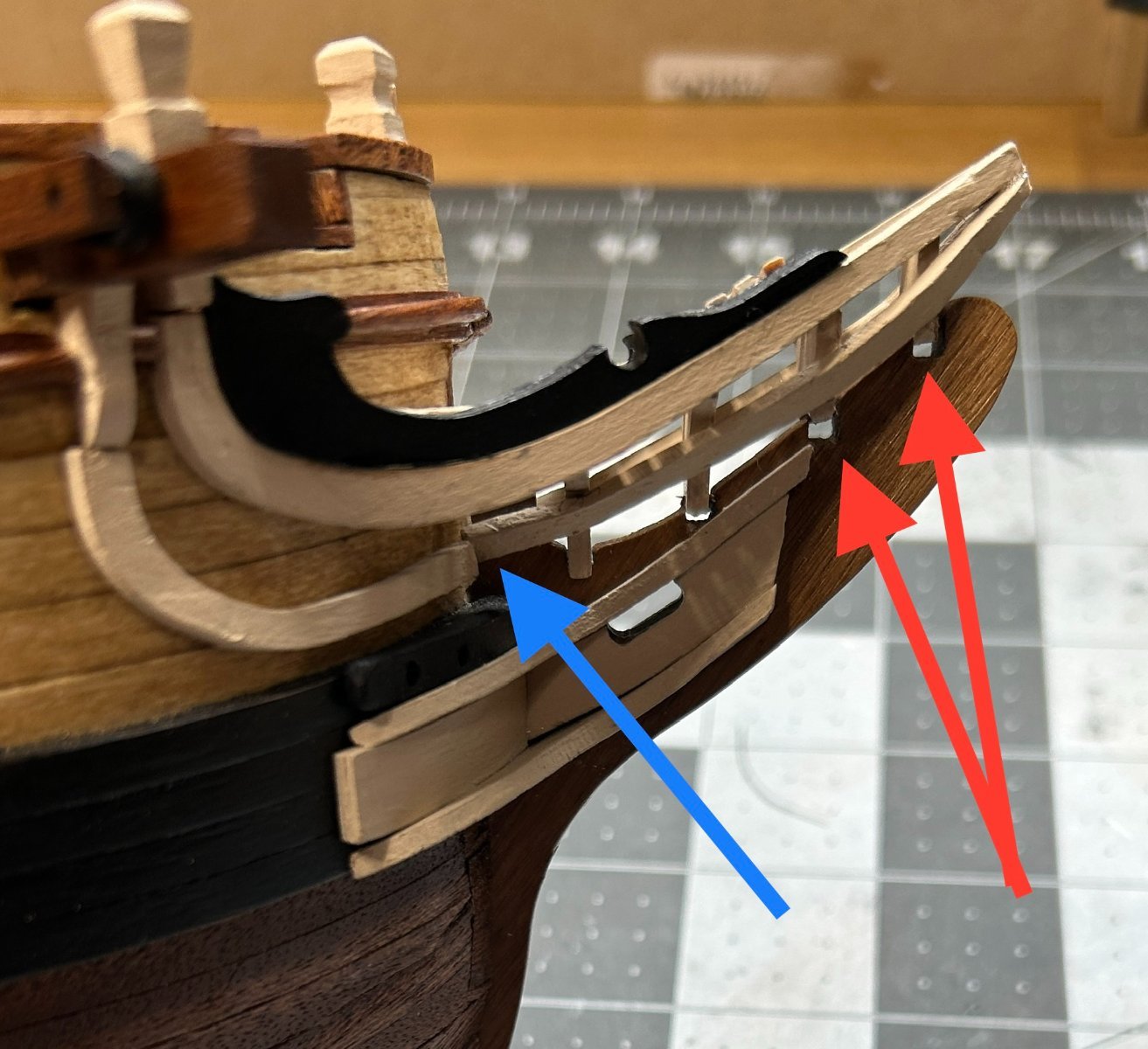
I have made progress on the head, but not without a few problems. Earlier when I glued the upper head rails on, positioned the front tips a little too high. I needed to shim the braces that sit on the stem with a thin piece of .06 mm wood. When I added the pieces below that are painted black to the top of the upper head they seamed to pull the head rails even higher leaving a gap between the stem and the braces for the grating. See the red arrows below.
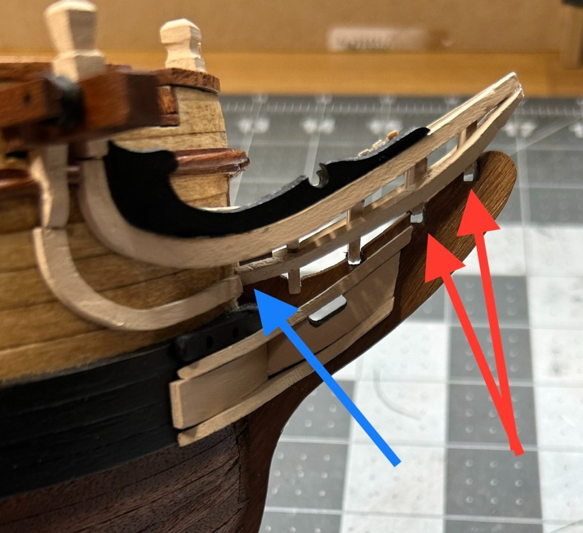
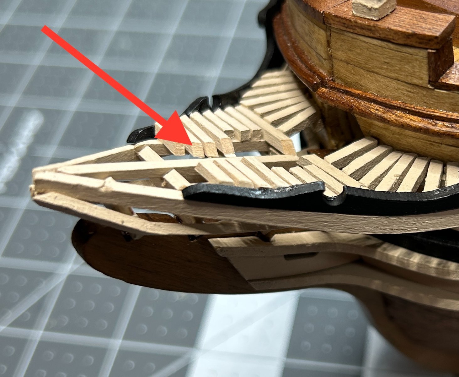
At first I wasn't too worried about this, but I realized that by raising the grating higher it was going to interfere with the bowsprite. To deal with this I needed to cut a channel in the grating to make room for the bowsprite.

I also struggled to properly bend the lower head rail. This peice needed to be bent to follow the curve of the bow and then bend sharply towards the tip of the stem. A twist in this part of the head rail was required so that the head rail could be glued to the bottom of the braces on the stem. The bend along the bow was not hard to achieve, but the piece broke where the sharp bend towards stem and the twist was needed. I ended up fabricating this out of two pieces, (see blue arrow above) and I am not thrilled with the point were the two pieces meet and might try to figure out a way to make that look better.
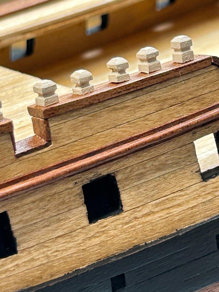
I also have the posts attached to the cap rail.
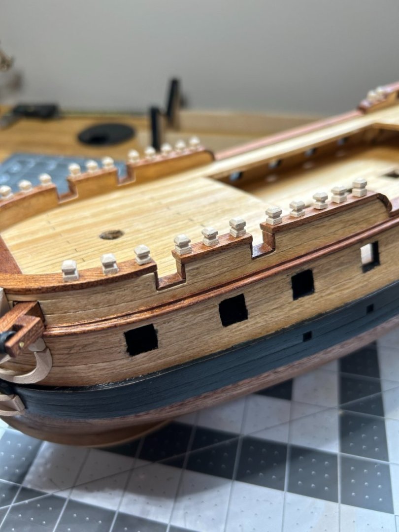

These were carved from a 4mm x 4mm piece of limewood using a file and a carving tool with a dremel
I added a pin to help hold them secure to the cap rail.

-
I think that contact cement is not given a fair shake on this forum. Does anyone have an example of planks coming off a model after ten years where contact cement was properly used? Contact cement is primarily used in the countertop industry for attaching laminate counter tops to wood subsurfaces. I am currently sitting in a 40 year old house with original laminate counter tops in the laundry room with no sign of the glue letting go. It is applied differently to other glues, you have to let it dry to the point of being barely tacky before the pieces are attached. If the pieces are attached too soon when the glue is still sticky, it doesn't set up properly. This could be the issue people have had.
I have not been involved in modeling for 10 years, so I cannot say with certainty that my my second layer of planking will not start to let go, but I am not very worried about based on the available information about the adhesive and the fact that I believe I used it properly.
-


.JPG.7e254a626e9adee2cf3f41330bc37de3.JPG)


HMS Diana by dunnock - FINISHED - Caldercraft - 1:64
in - Kit build logs for subjects built from 1751 - 1800
Posted
Great job. I followed your build closely and as someone still new to modeling, your craftsmanship is a standard I hope to achieve someday. Well done.