
.jpeg.882f0a147f14858c9e673da7e13d8ebe.jpeg)
RossR
-
Posts
315 -
Joined
-
Last visited
Content Type
Profiles
Forums
Gallery
Events
Posts posted by RossR
-
-
I have had similar experience. Even if you break or ruin an item by accident they will send a new one.
-
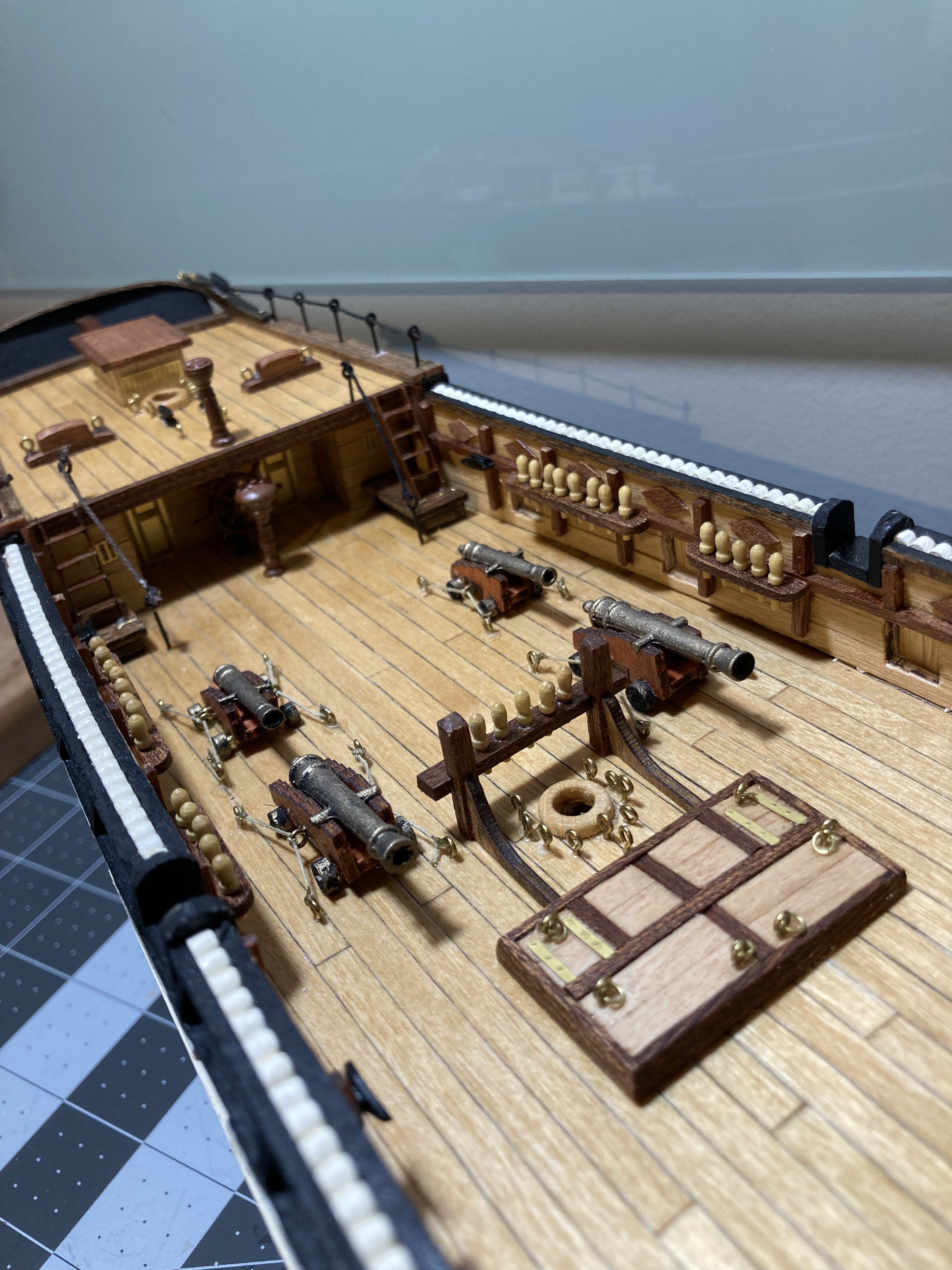
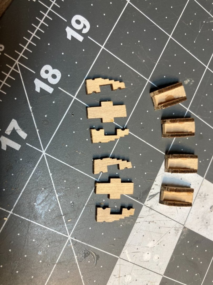
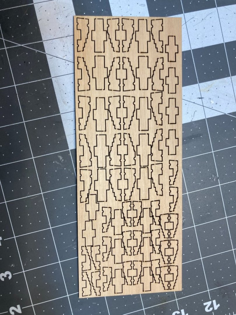
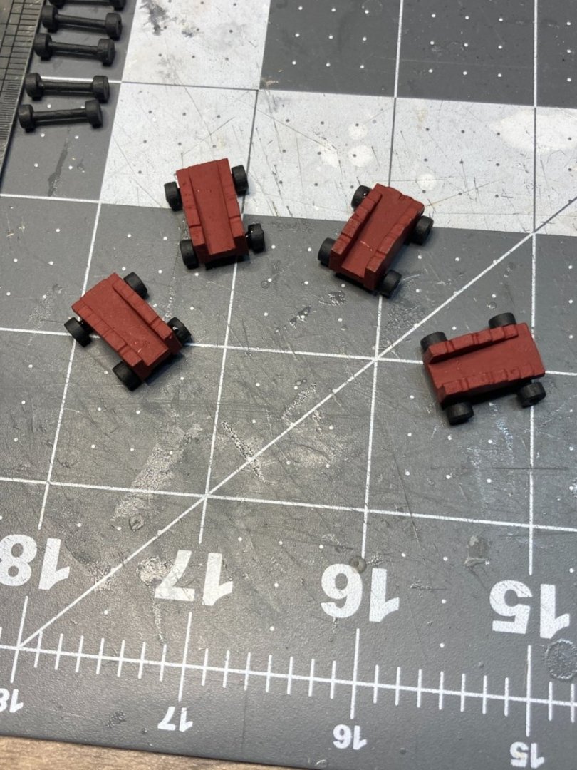
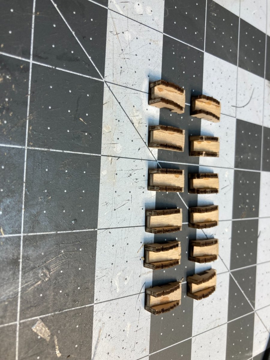
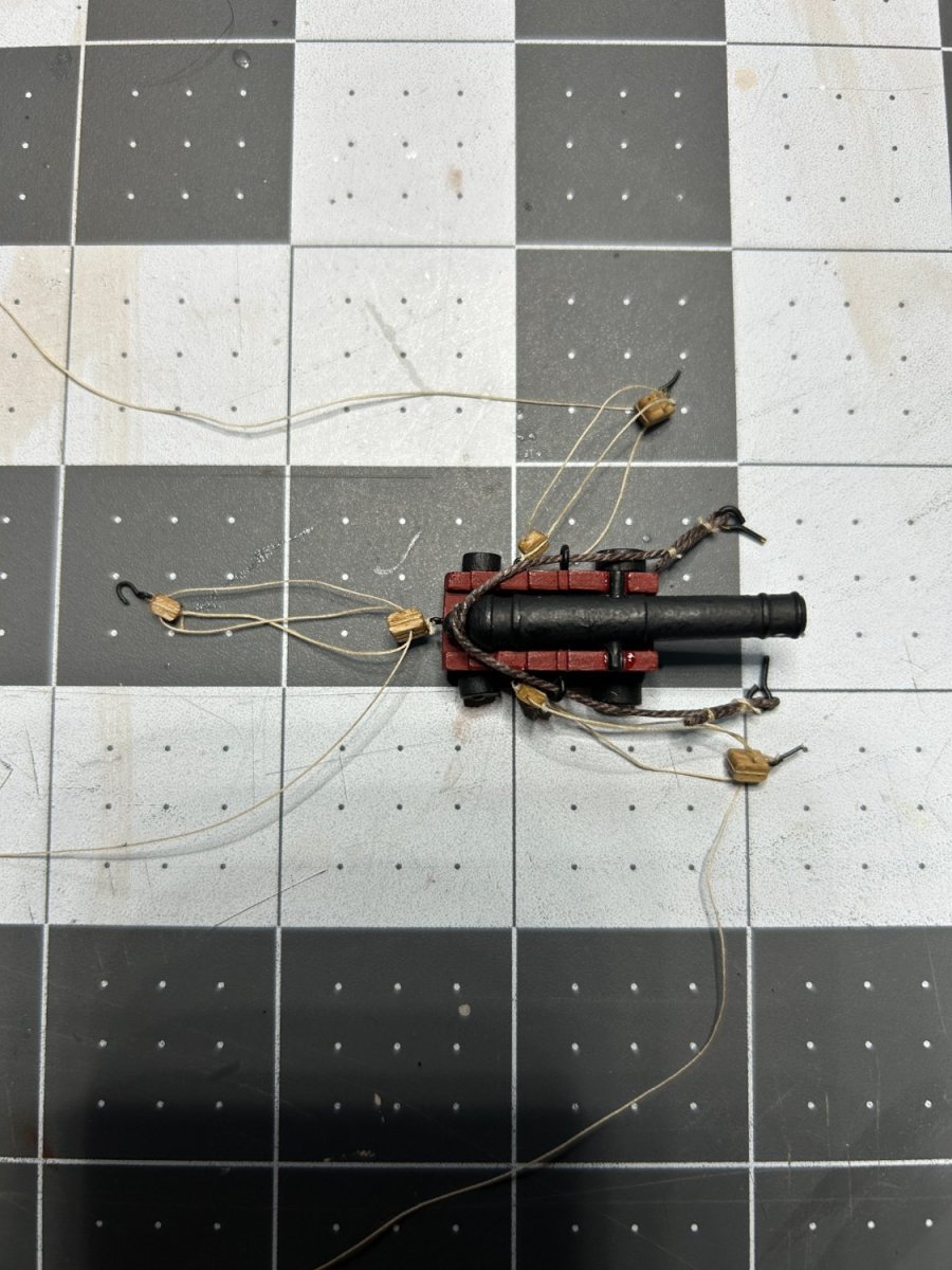
I still need to do the touch up work on the head, but I decided to take a break from the head and start work on the 12 pound guns for the lower gun deck. The kit has ten 12 pounders that are complete with a gun carriage, and I think 14 false barrels for the rest of the gun ports on the lower gun deck. First step was to assemble the carriages from the laser cut sheet. I assembled the 12 and 6 pounders that go on the upper gun deck.

I filled in the gaps with some filler and then painted the carriages a dark red.
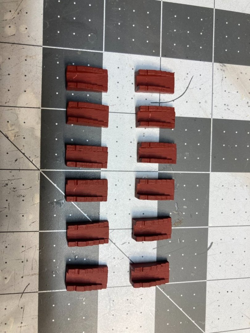
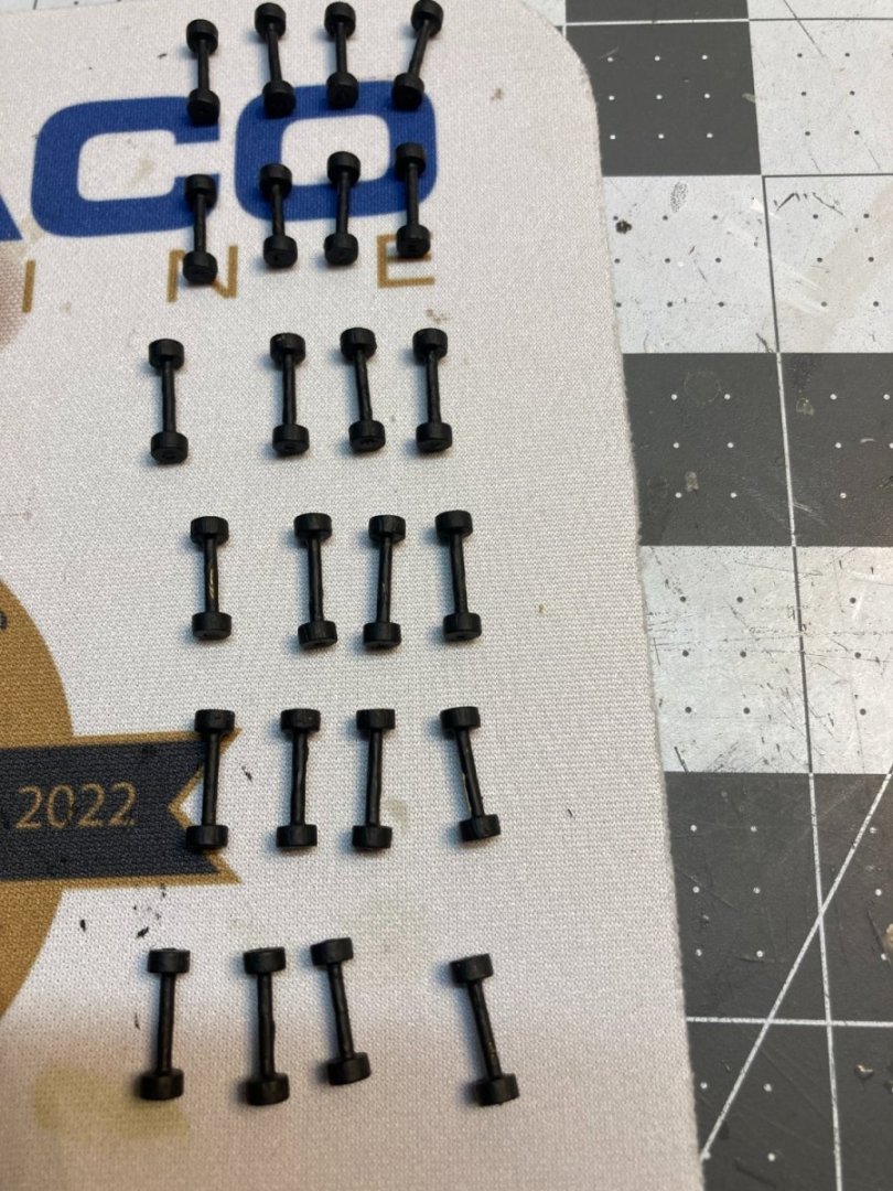
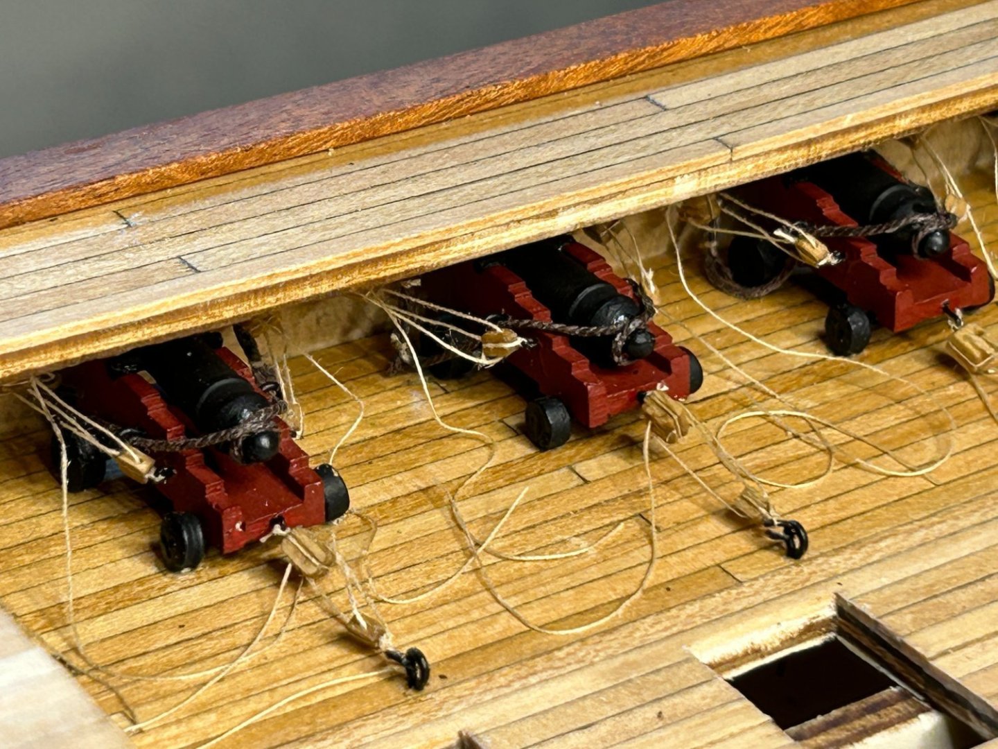
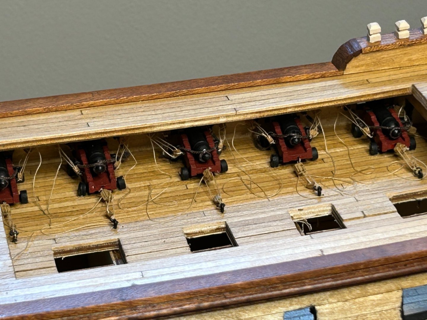
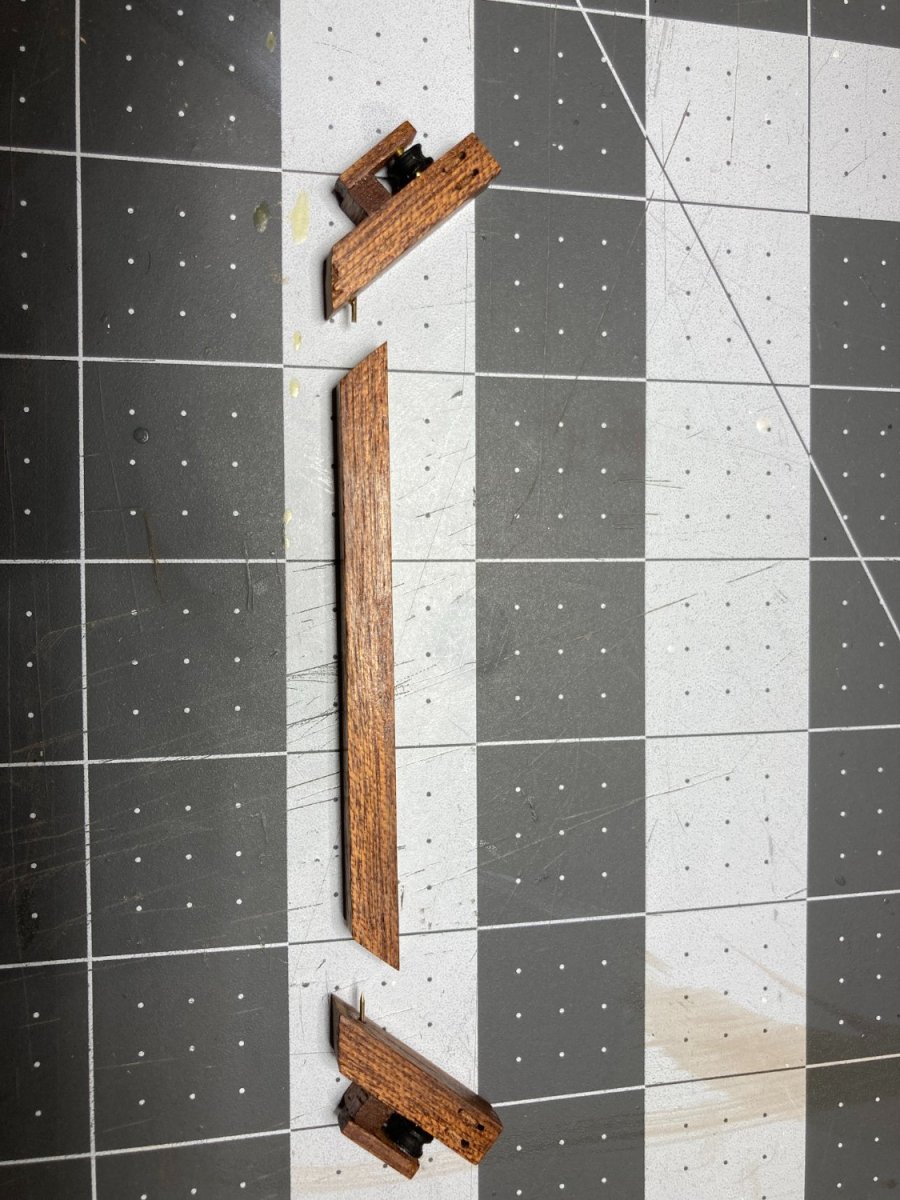
Next up was building the axles. There were two sizes of wheels. I assumed that the smaller wheels were all for the 6 pound carriages and the bigger wheels for the twelve pounders. I assembled all of the smaller wheels on axles that fit on the 6 pound guns only to realize that the smaller wheels were also needed for the rear wheels on the 12 pound carriages. I had to cut the axles apart to get them to fit on the bigger 12 pound carriages.
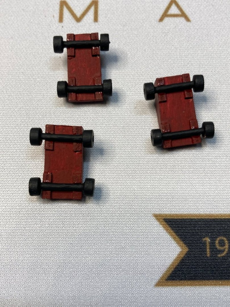
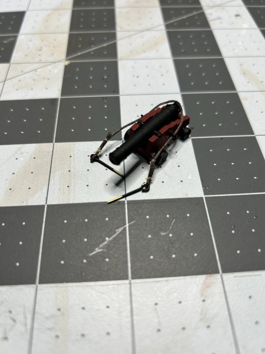
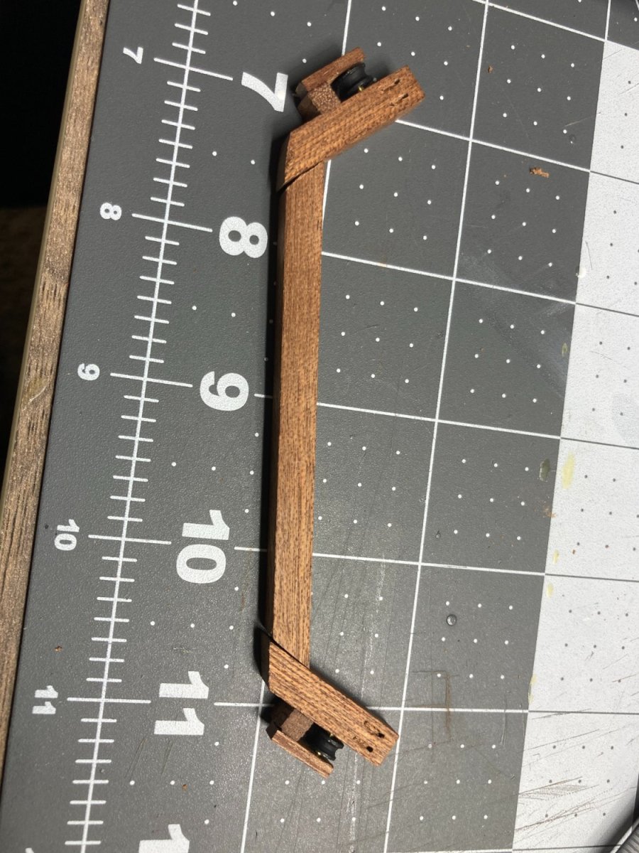
I decided that I wanted to rig the guns. I think a lot of people on the this forum might suggest not doing that on a 1:85 scale model, and they might be right, but with this model I wanted to do things that I didn't do on my first model, so I am going to add the rigging to the guns. You will also notice something odd with one of the wheels on the picture below. I lost one of the wheels and didn't want to wait for a replacement, so I repurposed a leftover deadeye from my HMS Beagle.
.thumb.JPG.1727a76173d1a184b4a3cd13a8f933b4.JPG)
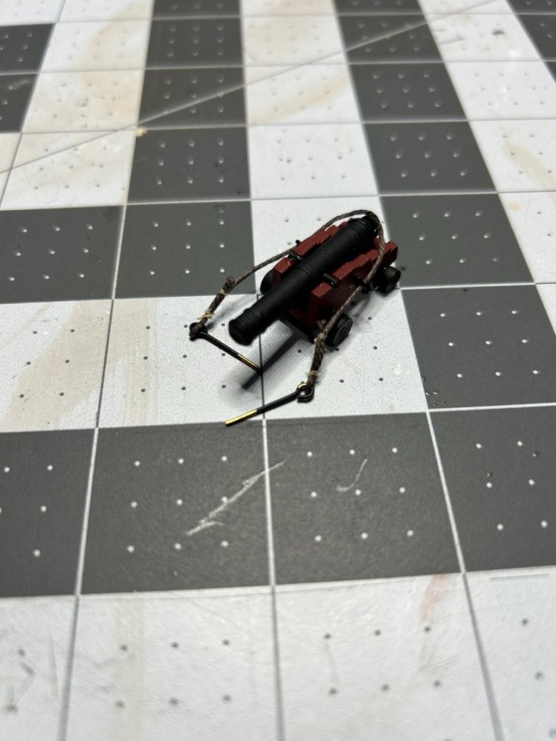

Attaching the blocks to the ship was a real challenge given the deck that overhung the gun deck. I am hoping to rig my ship as it might have looked in action, so I decided to show the lines for the gun tackle laying on the deck as opposed to neatly coiled up. I did have to abandon the hook that attached to block at the rear of the gun to the ring on the deck because the two blocks were too close together with the hook.
- KurtH, GrandpaPhil, Esap and 2 others
-
 5
5
-
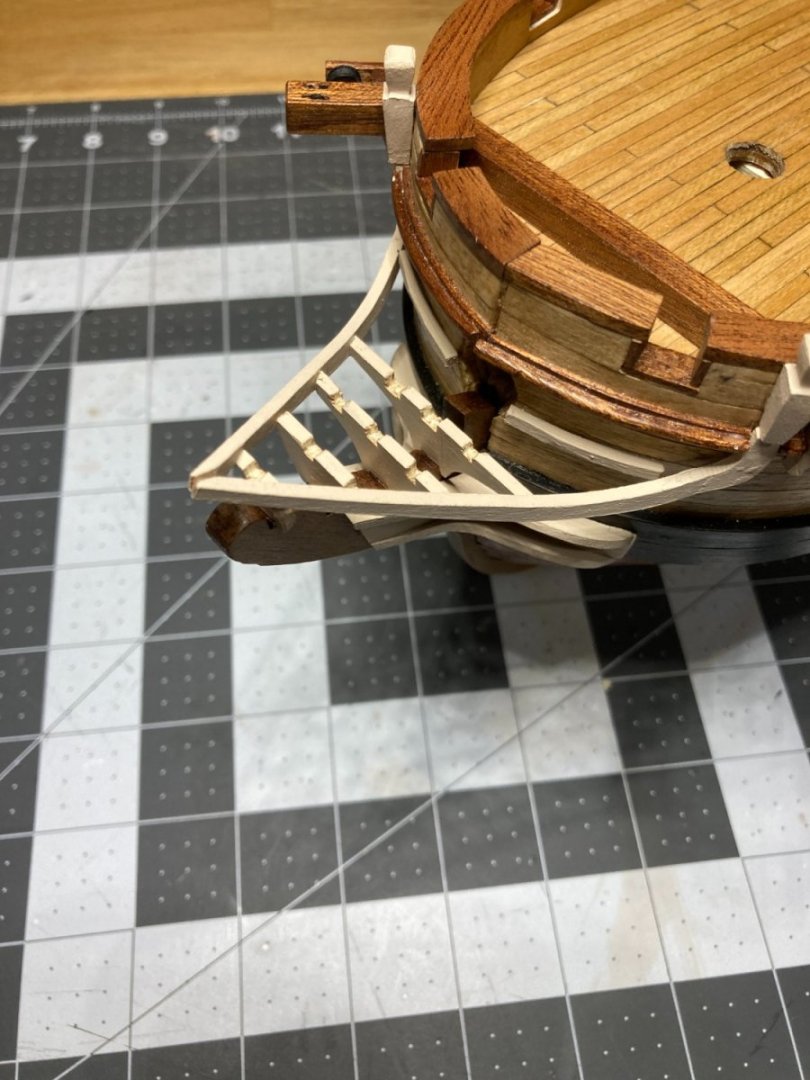
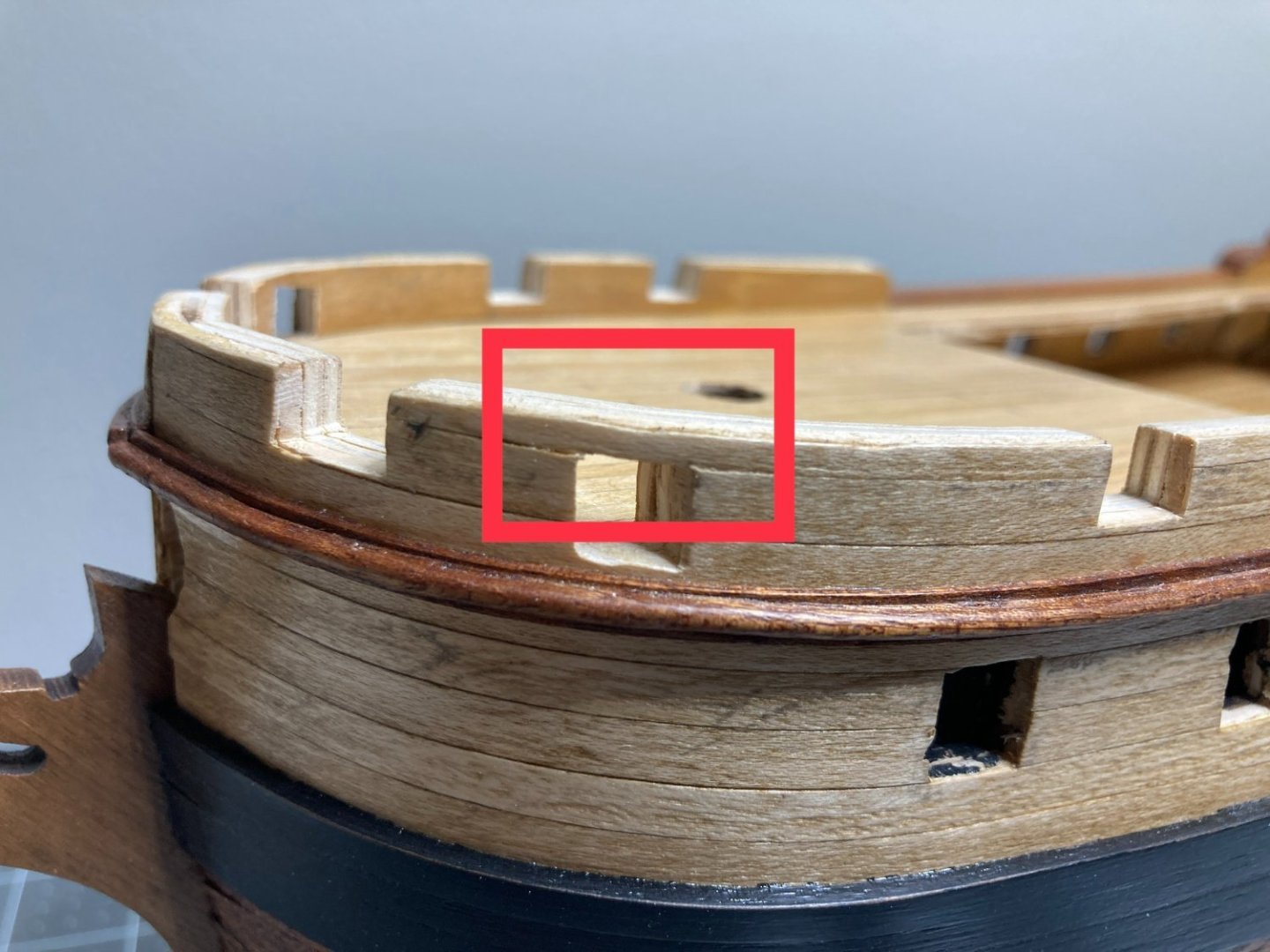
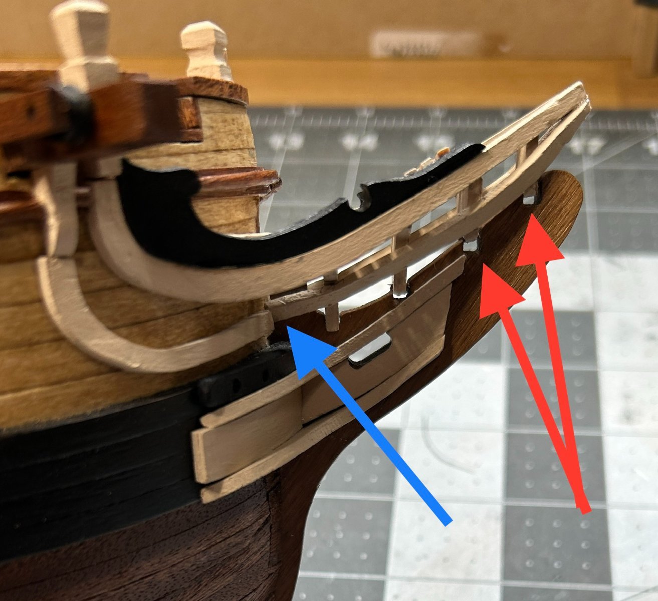
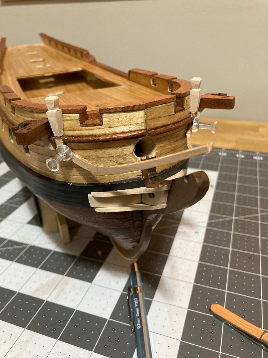
I have made progress on the head, but not without a few problems. Earlier when I glued the upper head rails on, positioned the front tips a little too high. I needed to shim the braces that sit on the stem with a thin piece of .06 mm wood. When I added the pieces below that are painted black to the top of the upper head they seamed to pull the head rails even higher leaving a gap between the stem and the braces for the grating. See the red arrows below.
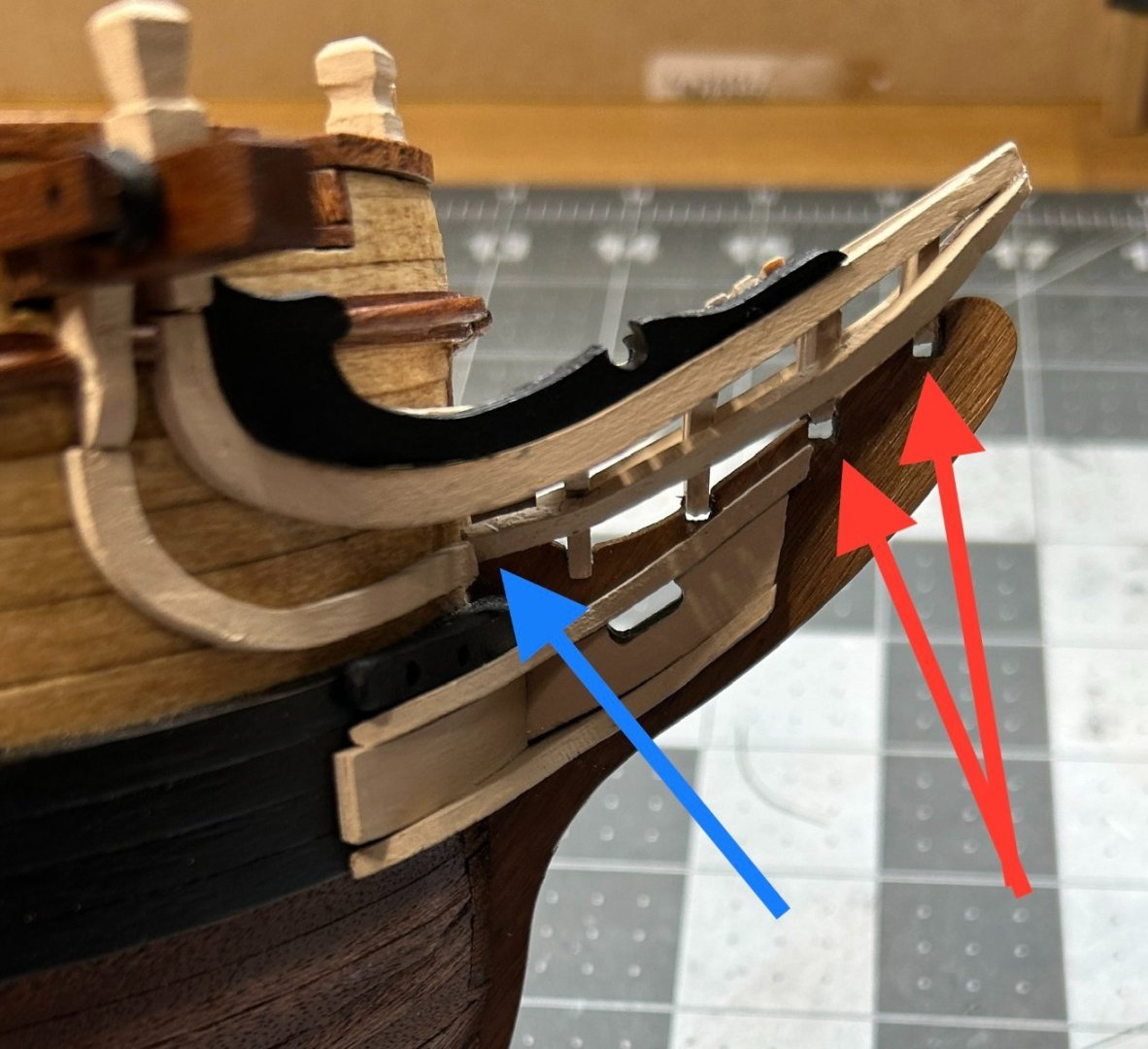
At first I wasn't too worried about this, but I realized that by raising the grating higher it was going to interfere with the bowsprite. To deal with this I needed to cut a channel in the grating to make room for the bowsprite.

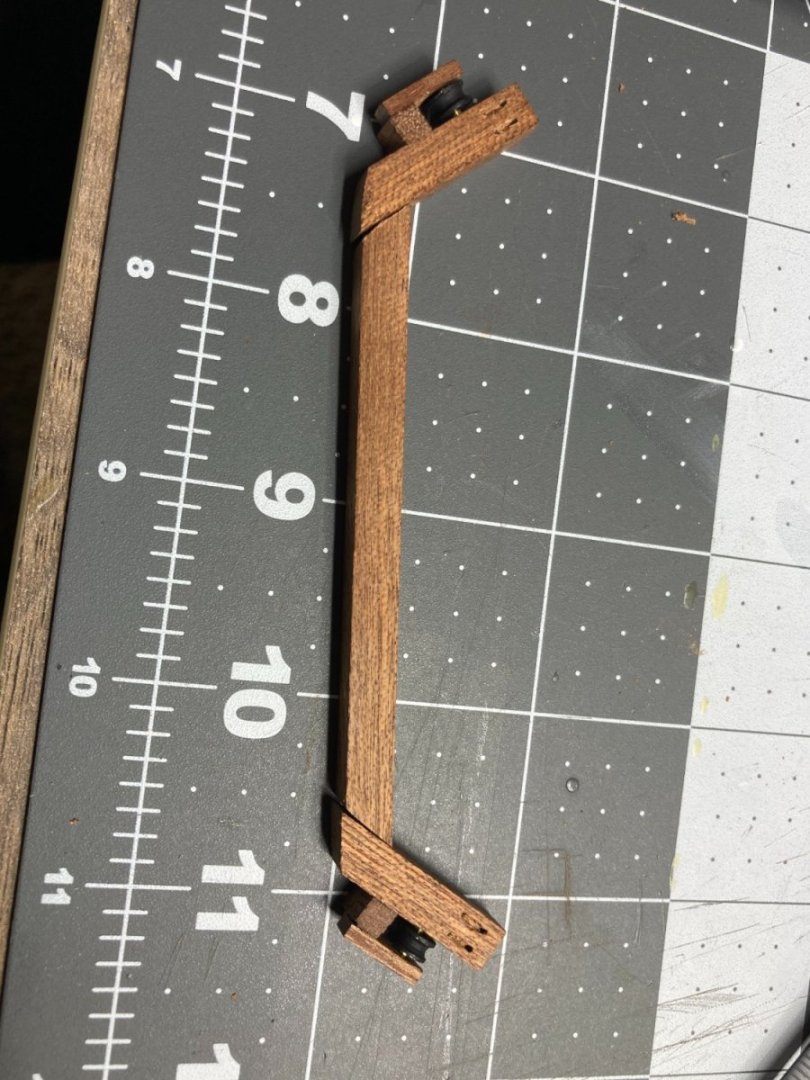
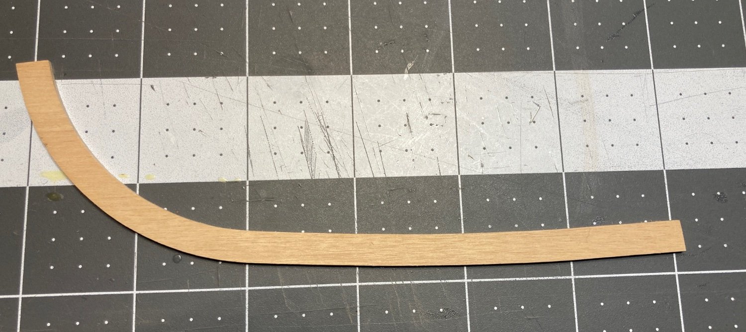
I also struggled to properly bend the lower head rail. This peice needed to be bent to follow the curve of the bow and then bend sharply towards the tip of the stem. A twist in this part of the head rail was required so that the head rail could be glued to the bottom of the braces on the stem. The bend along the bow was not hard to achieve, but the piece broke where the sharp bend towards stem and the twist was needed. I ended up fabricating this out of two pieces, (see blue arrow above) and I am not thrilled with the point were the two pieces meet and might try to figure out a way to make that look better.
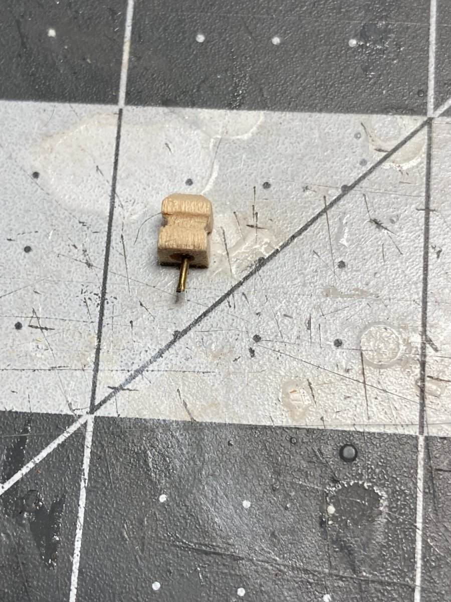
I also have the posts attached to the cap rail.

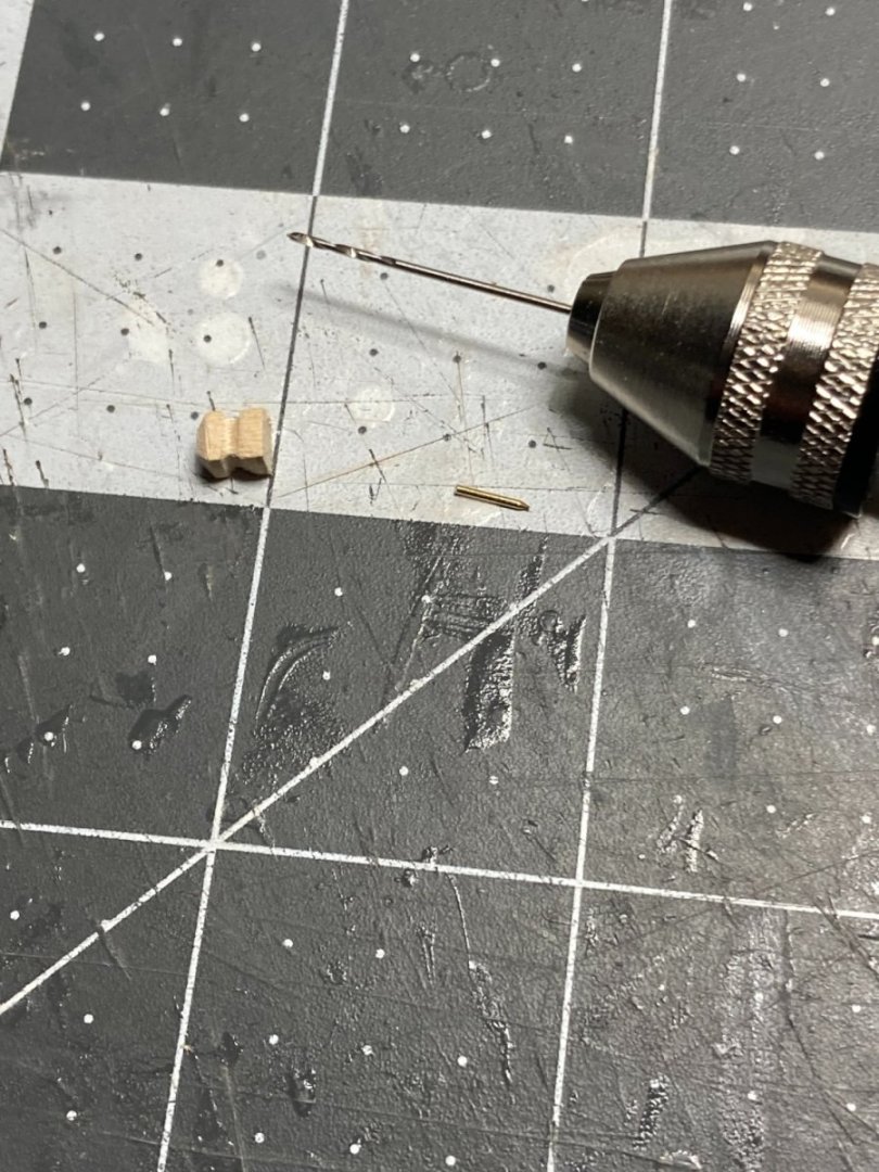
These were carved from a 4mm x 4mm piece of limewood using a file and a carving tool with a dremel
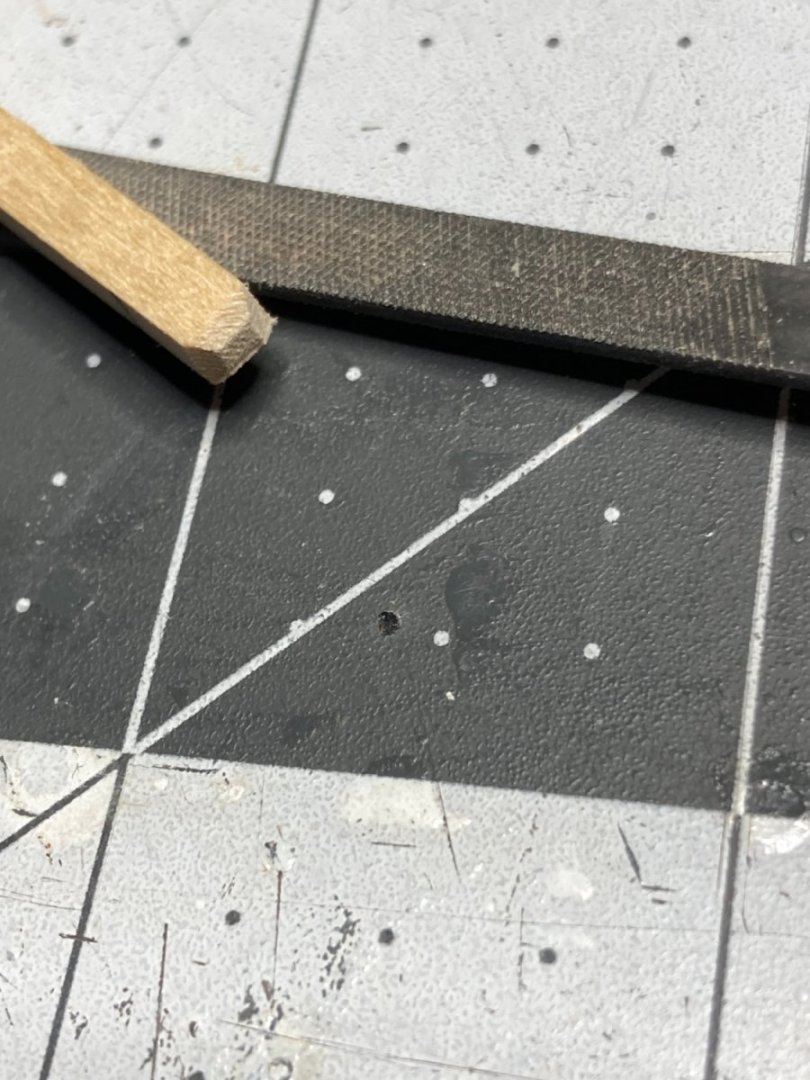
I added a pin to help hold them secure to the cap rail.

-
I think that contact cement is not given a fair shake on this forum. Does anyone have an example of planks coming off a model after ten years where contact cement was properly used? Contact cement is primarily used in the countertop industry for attaching laminate counter tops to wood subsurfaces. I am currently sitting in a 40 year old house with original laminate counter tops in the laundry room with no sign of the glue letting go. It is applied differently to other glues, you have to let it dry to the point of being barely tacky before the pieces are attached. If the pieces are attached too soon when the glue is still sticky, it doesn't set up properly. This could be the issue people have had.
I have not been involved in modeling for 10 years, so I cannot say with certainty that my my second layer of planking will not start to let go, but I am not very worried about based on the available information about the adhesive and the fact that I believe I used it properly.
-
-
I love GrandpaPhil’s goal and quote in his signature.
- GrandpaPhil, Ryland Craze, Keith Black and 1 other
-
3
-
 1
1
-
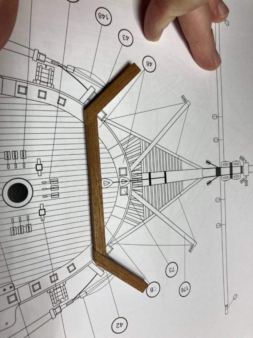
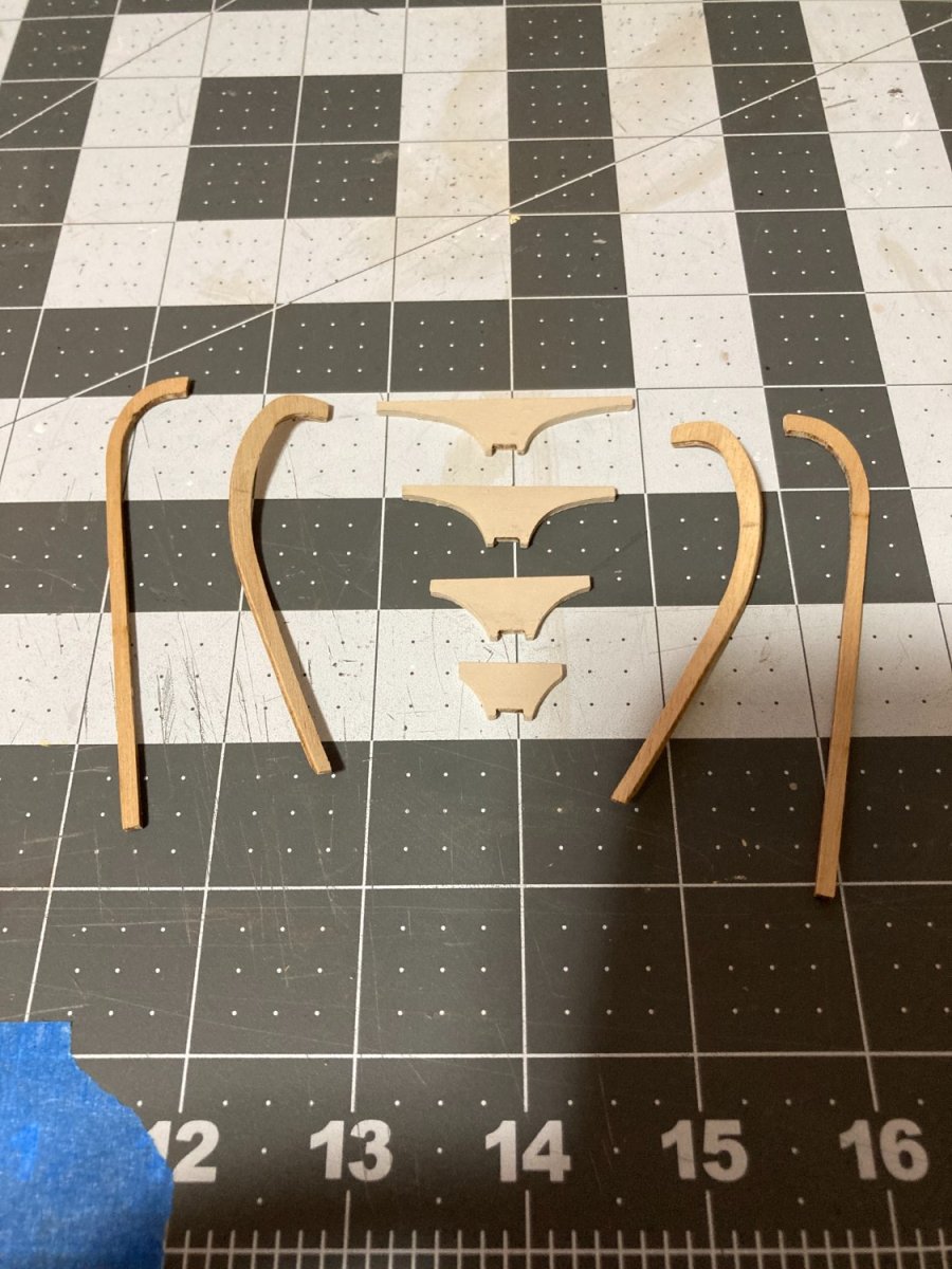
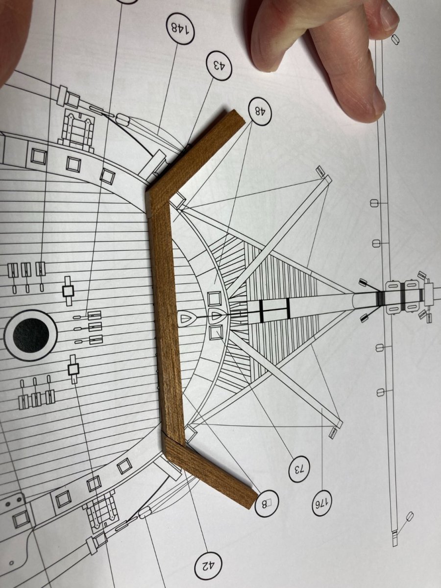
I have made some progress on the head. The head is made up of an upper and lower head rail and four supports that are mounted on the stem and support the grating. The upper head rail needs a slight bend right at the point it is secured to the bow.

The supports were oversized allowing the building to trim them so they fit tightly between the two upper head rails. The get the supports cut to the right size I temporarily pinned the upper rails in place.


After getting the supports cut to size, I painted all of the parts and used CA to glue the head rails to the bow and the tips of the head rails to each other along with attaching them to each of the four supports.

I will need to touch up a few spots of paint Next steps will be adding braces across the supports and adding the lower head rail. The lower head rail will be challenging. The part needs to be bent to fit the curve of the bow for the first 1/3 of the part then it needs to twist 45 degrees so it can be secured to the underside of the four supports.
-
-
-
Welcome. Nice to have another Minnesotan on the forum.
- Keith Black and mtaylor
-
2
-
Today I made some progress on the ship. The new shipyard is working great. my work light set up still.
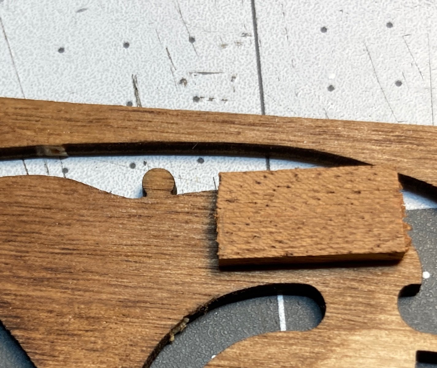
A couple of posts ago I had cut out new cap rails (I think that is the correct term) for the bow section out of basswood after not caring for the way the plywood pieces looked on the edges. I struggled to get the color of the basswood close the sapelli that was used for the rest of the cap rail. Then I was driving past a hobby shop and stopped in and found a piece of 3/32 mahogany. I re-cut the cap rail out of the mahogany and was much happier with the result.
After getting the cap rails installed I added some of the other features that need to be installed before the head can be fabricated. I had to carve the posts next to the cathead and added some items to the stem.


-
Your progress is incredible. Looks great so far.
- Knocklouder and mtaylor
-
2
-
I had today free to work on my ship. Plans changed when my wife was shopping and stopped at a business that was having a moving sale. She found two 6 ft x 2 ft butcher block tables and picked them up for an upgrade to the shipyard. I had been doing my work at a small desk in the back of our family room. She also generously gave up her home office for me to set up my new shipyard. It will take me a little time to get everything organized the way I want, but this is way more room than what I had before. Looking forward to the new space.
.thumb.JPG.0bed0771f0d2d791edbc88b32c069419.JPG)
- Esap, CiscoH and VitusBering
-
2
-
 1
1
-
-
-
Thanks for sharing your technique. I think I will try this on my current build.
- DaveBaxt, mort stoll, Dave_E and 1 other
-
4
-
Great job. your ship looks great.
-
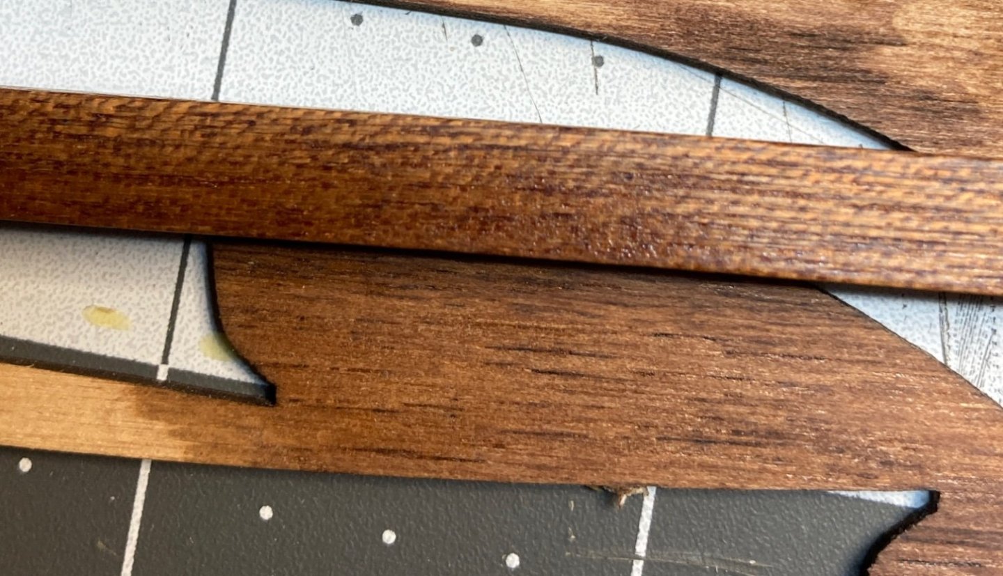
After staining and finishing the laser cut pieces for the bow, I was not happy with the look of the edges. The middle layer of the plywood ended up almost black.
I had recently acquired a scroll saw from my father, so I decided to attempt to cut replacements out of piece of 3/32 basswood.
I am pretty happy with the outcome. I need to go back to the drawing board on figuring out a stain that will match the Sapelli.
-
-
Is it possible your drill bit is dull or damaged at the tip?
- Keith Black, Bob Cleek and mtaylor
-
3
-
-
One more challenge with the bow section is related to finishing the material provided with the kit. Most of the trim is Sapelli. For the bow a laser cut piece of plywood (looks like birch) is provided to accommodate the curve on the bow.
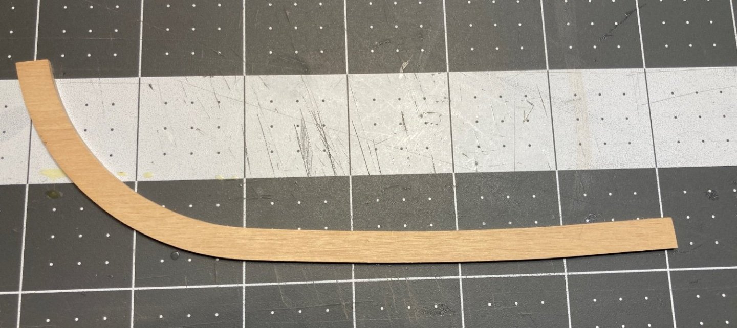
finishing these pieces to look like Sapelli is a challenge. I originally tried to match the bare Sapelli. A mix of Provincial and Gunstock stain came pretty close.

however, when Sapelli is finished with Shellac it takes on a darker rich color. Covering the stained plywood with shellac didn’t produce the same dark rich color.
I bought some Red Mahogany stain but is wasn’t quite right. I then applied the Provincial stain first, then added a coat of the Red Mahogany, and after a couple coats of shellac it was pretty close.
I think it will take 4, maybe 5 coats of shellac to get the richness, but this should work.
-
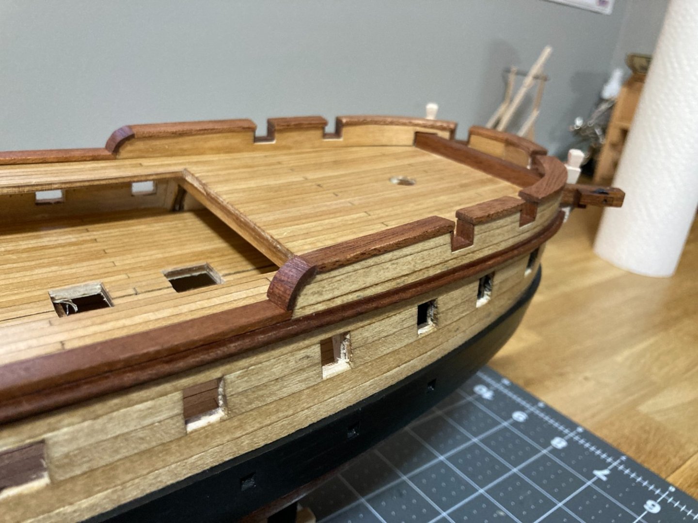
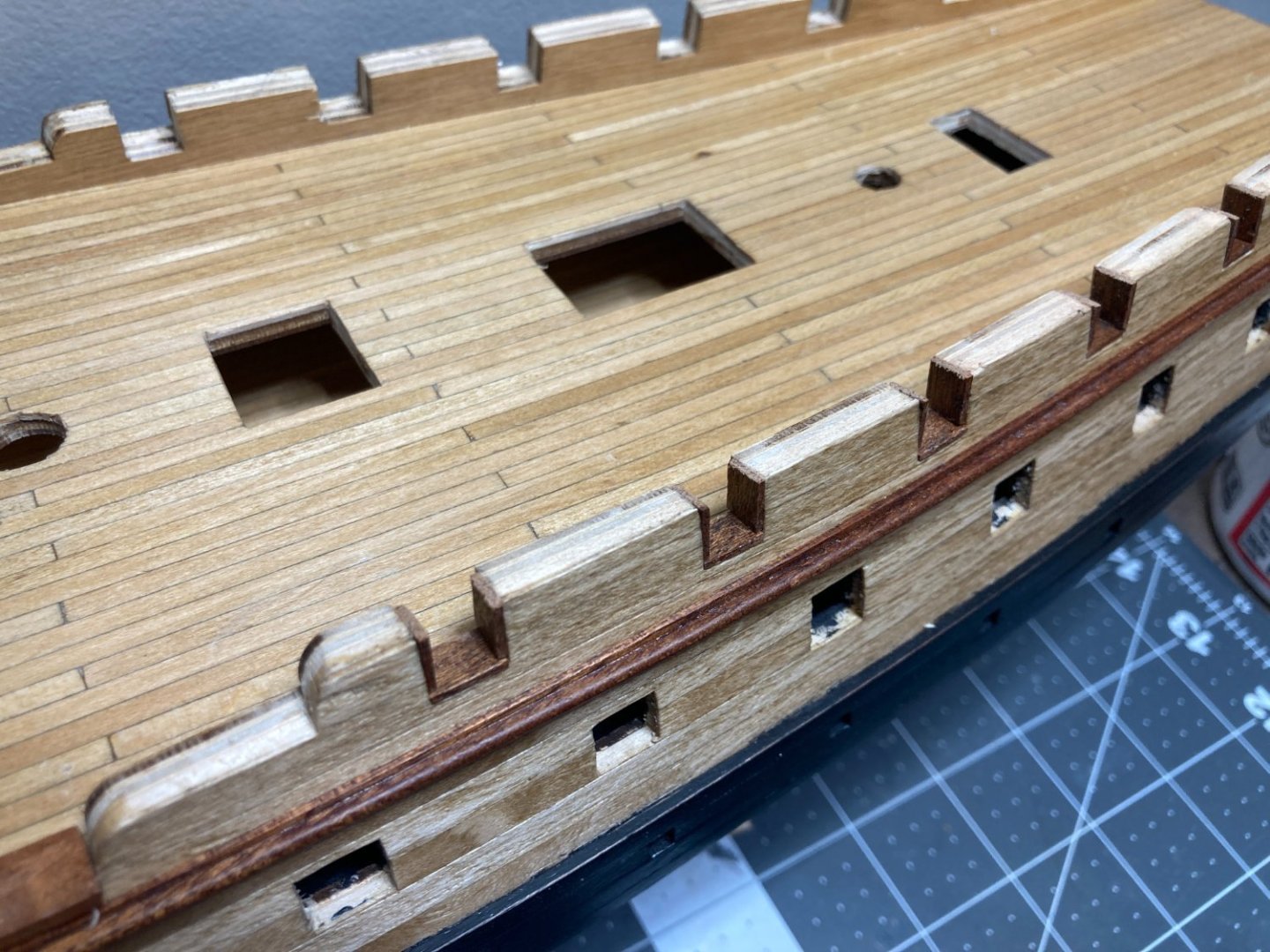
I finished the trim on the rear part of the ship, and I am pretty happy with how that turned out. next, I am giving a light sanding and one final coat of shellac to the deck. I put a few marks into the deck finish while sanding and filing the trim features, so hoping a light sanding and another coat will help.
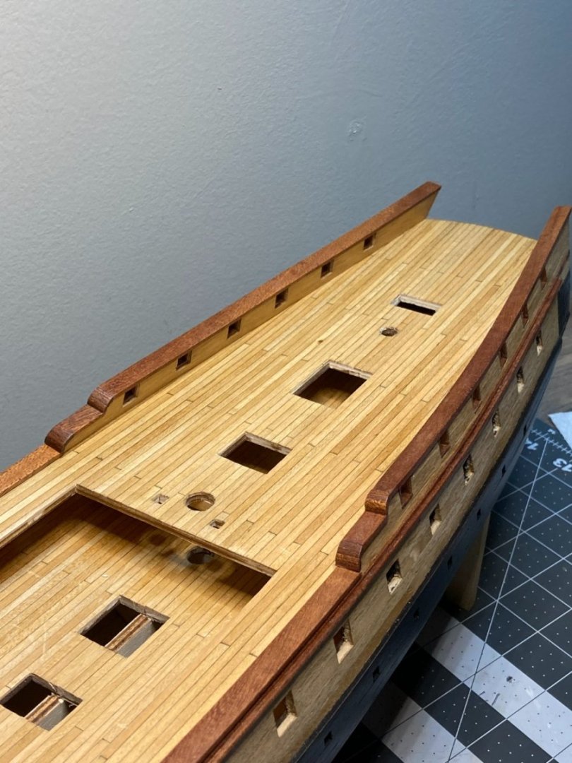
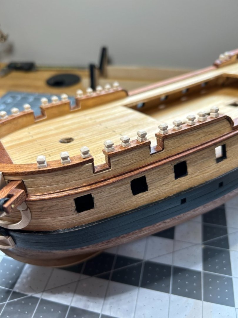
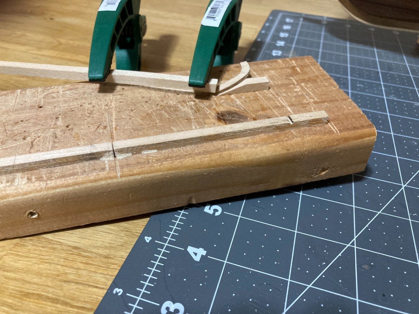
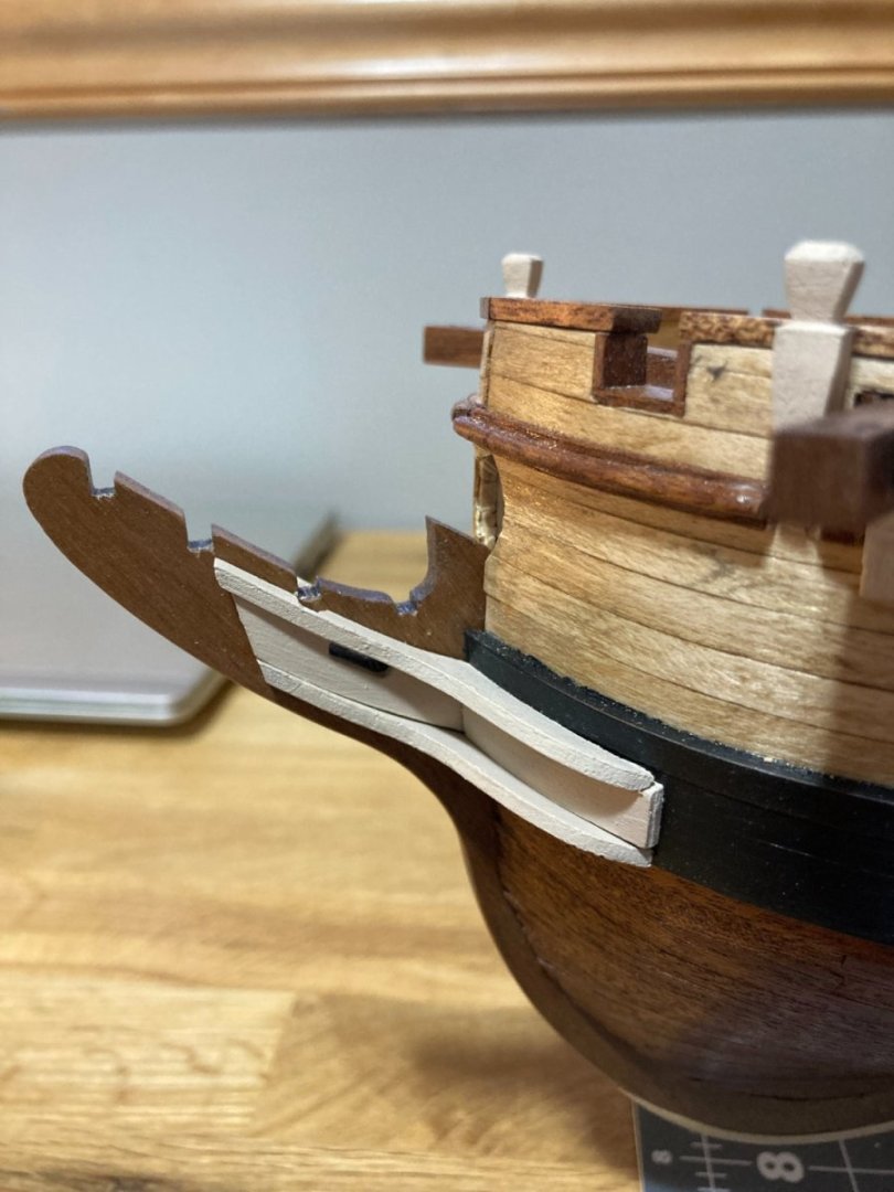
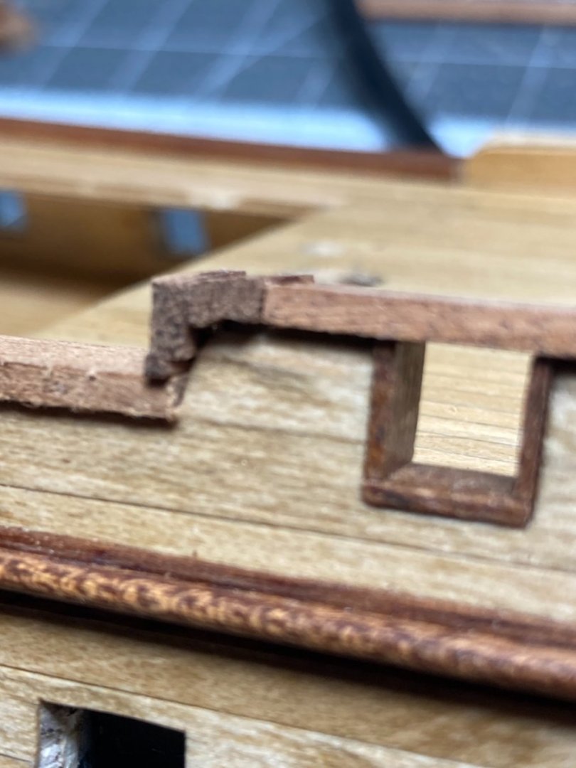
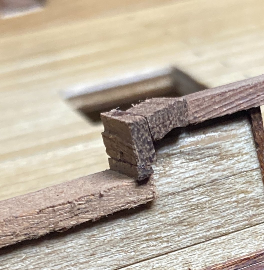
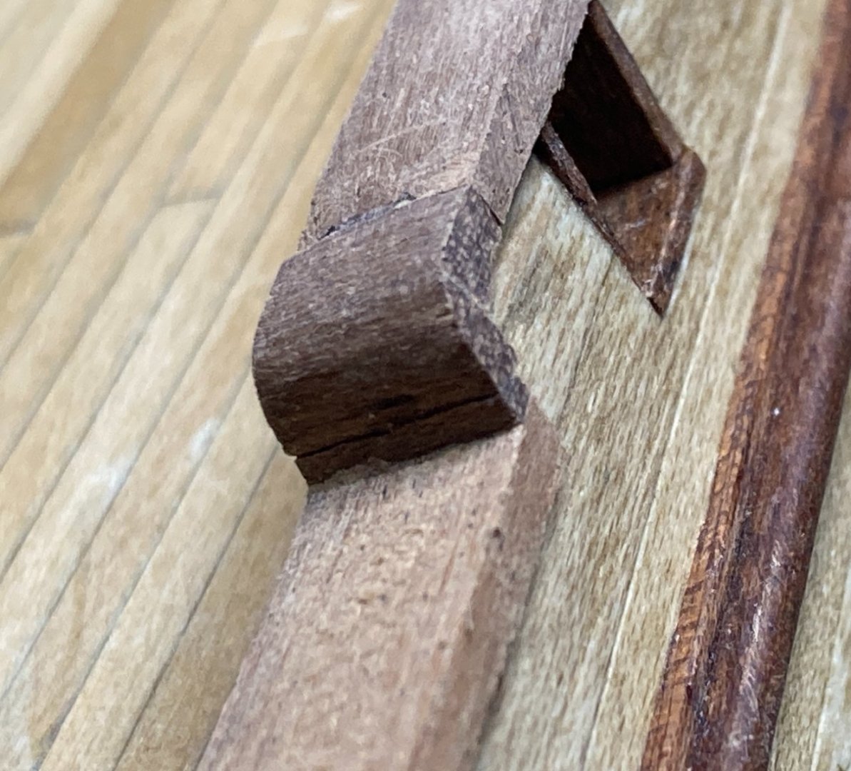
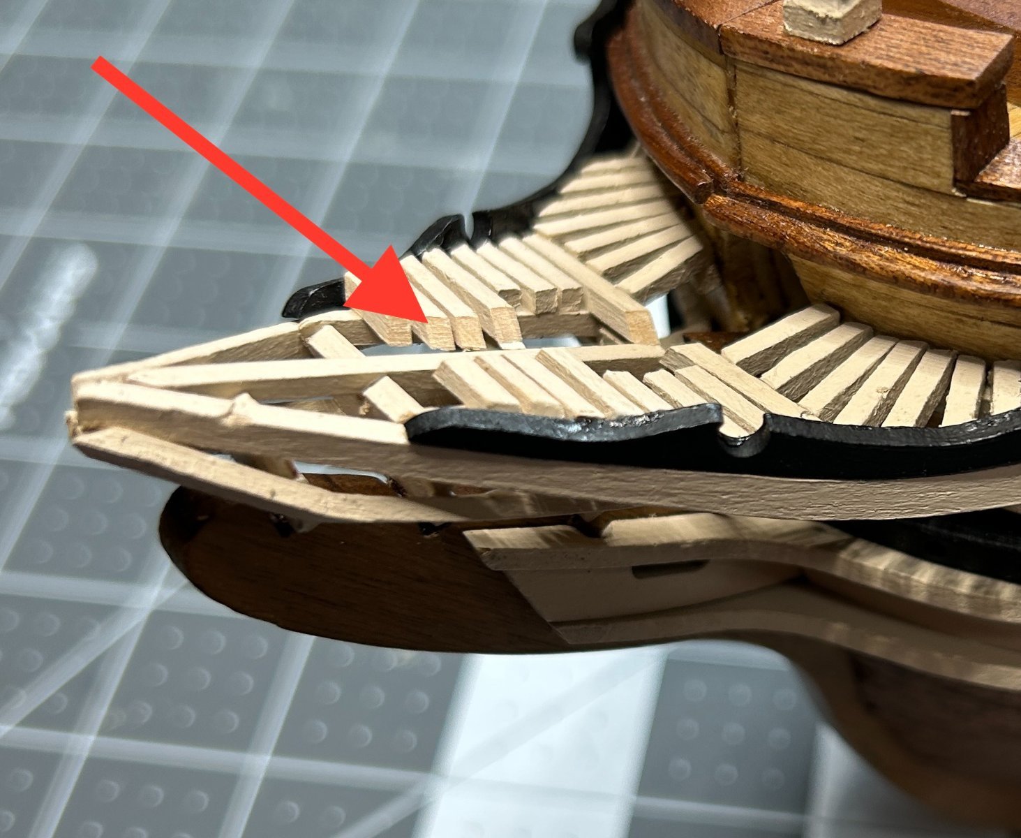
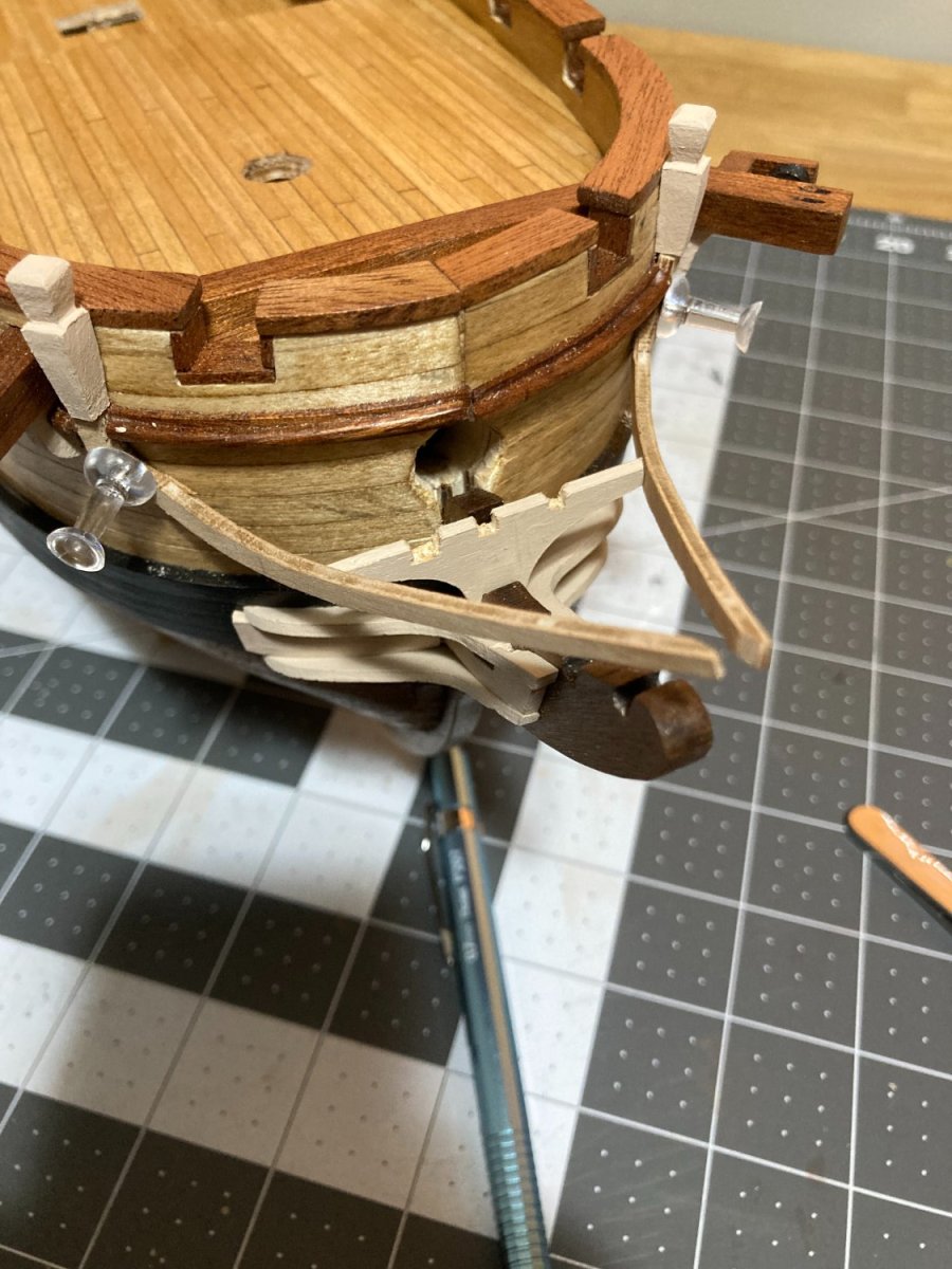
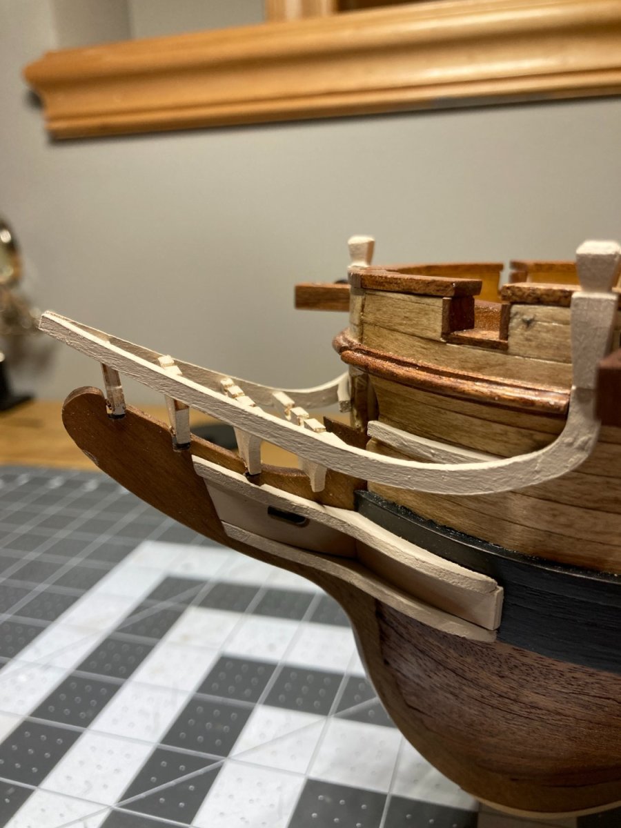
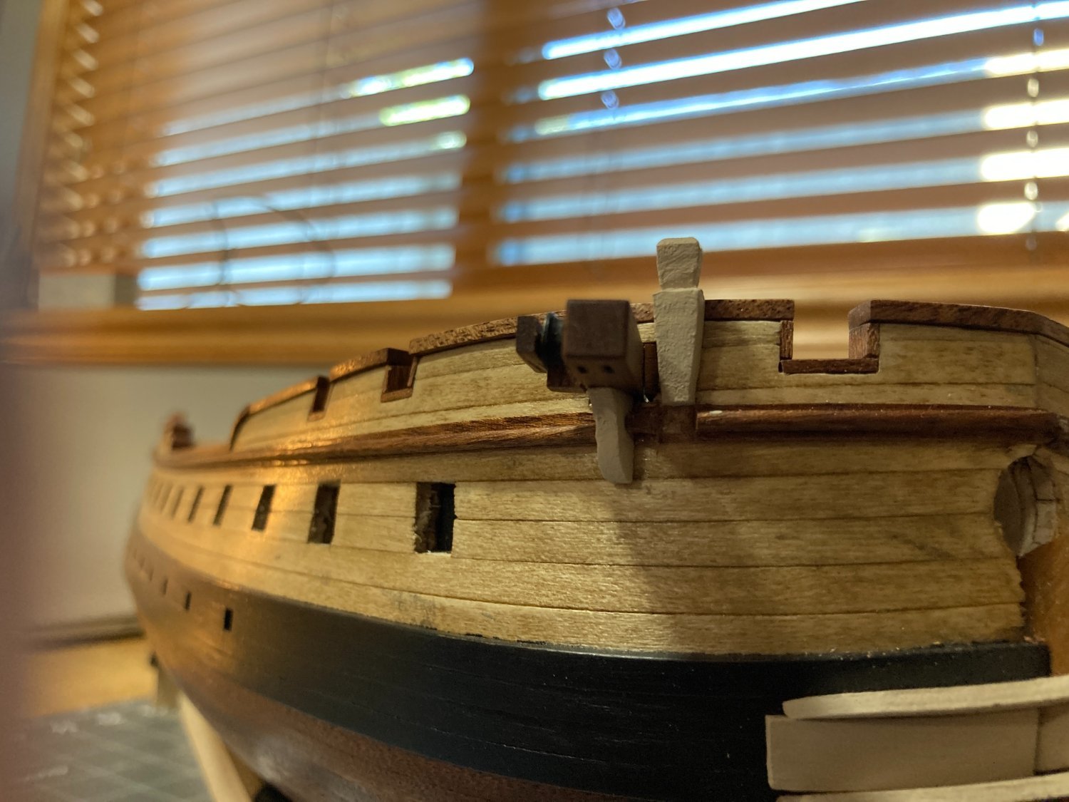
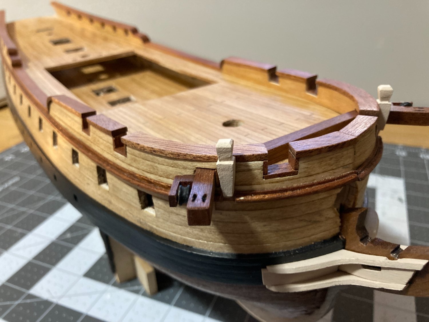
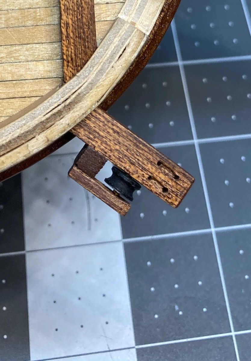
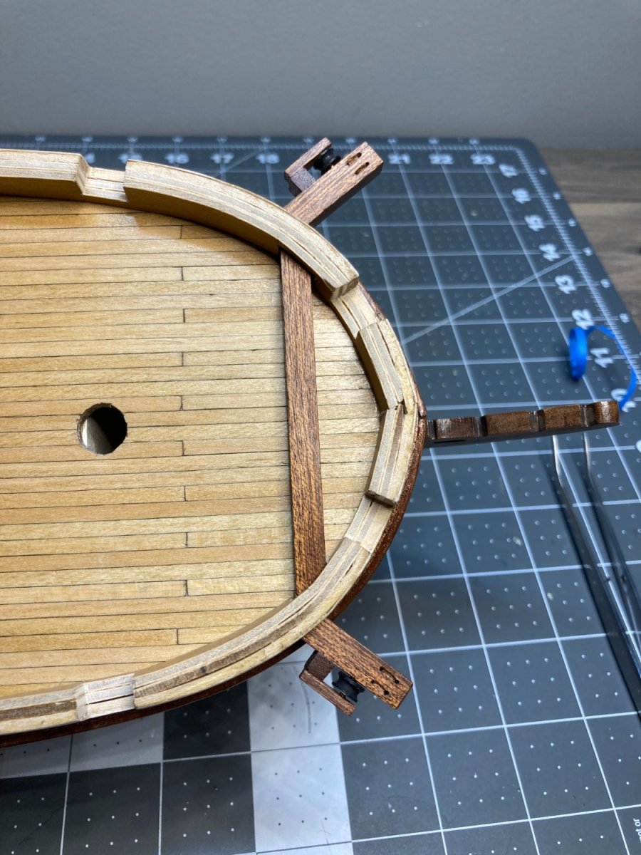
Next is the trim around the gun ports on the bow. I am calling these gun ports, but the kit does not have guns for this section of the ship. This part of the build will also include fabricating and installing the cathead. The instructions from Occre have you cut the top part of the bulwark above the cathead out and then attach the fully fabricated cat head on the ship (see picture below). Since all of the planking is on and finished, I don't want to cut that away. I have been making a few dry runs at assembling the cathead in place without cutting away the planking.
The other odd thing about the cathead is the pictures in the instructs appear tohave the cathead angling forward at about 30 degrees, but the plans clearly show a forty five degree angle. I will go with the 45 degree angle on mine.
Since very little of the piece that extends out from the hull is supported by the hull, I am going to add a pin to help secure it to the larger piece.

-
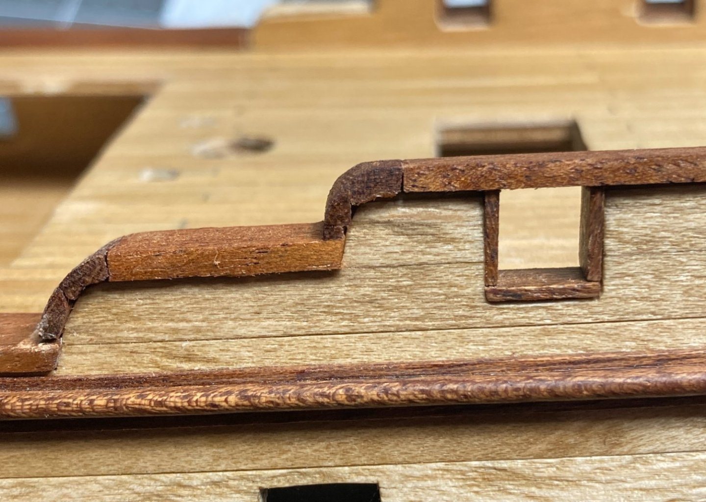
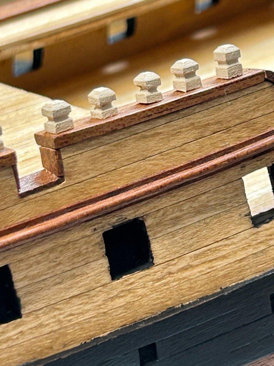
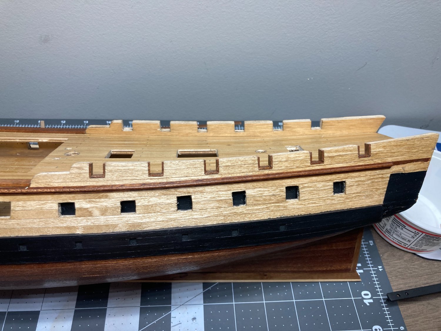
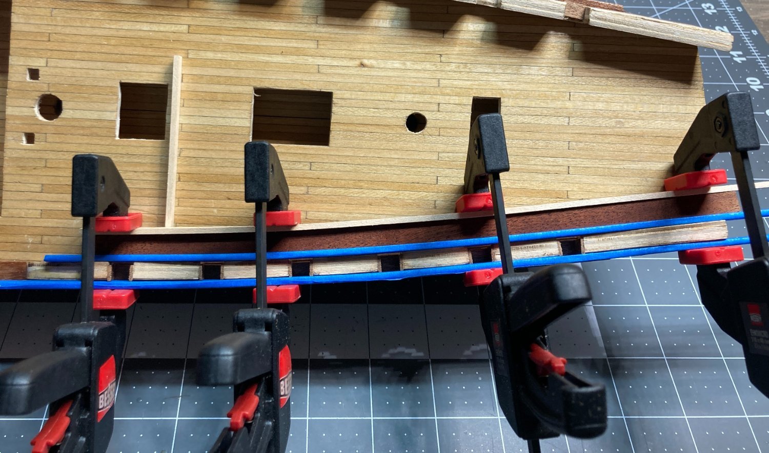
Making progress on the trim on the bulwarks and around the gun ports. The first step was lining the gun ports. 1mm x 6 mm sapelli strips were used for this.
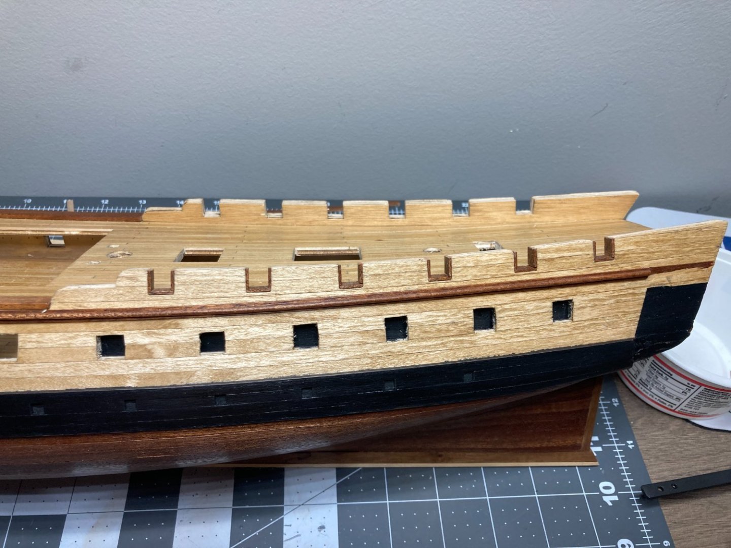
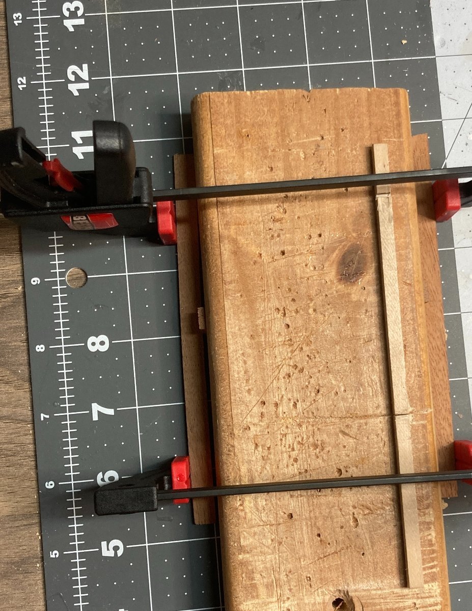
Next step was the cap above the section with no bulwark and the top of bulwark on the back half of the the ship. These were made out of 2mm x 8mm sapelli strips. Both have a slight bend. The bend was slight enough that I could manually bend the strip the required amount, but with the 2 x 8 strip the force of the strip to snap back to straight was pretty great. I considered manually bending the strip and using CA to glue them into place, but I have read that CA does not hold good against shear forces. I considered PVA which holds better against shear forces, but I couldn't think of a good way to clamp the pieces into place. My solution was to pre-bend the pieces and then glue with CA. for the slight bend in the mid-ship pieces where there is no bulwark, I clamped it against the straight piece of wood after soaking for 30 minutes with a small shim used to create the curve. For the piece above the bulwark on the rear portion of the ship, I clamped the piece to the bulwark after soaking to create the curve needed. I used scrap wood to protect the ship and the piece being bent from the clamps.


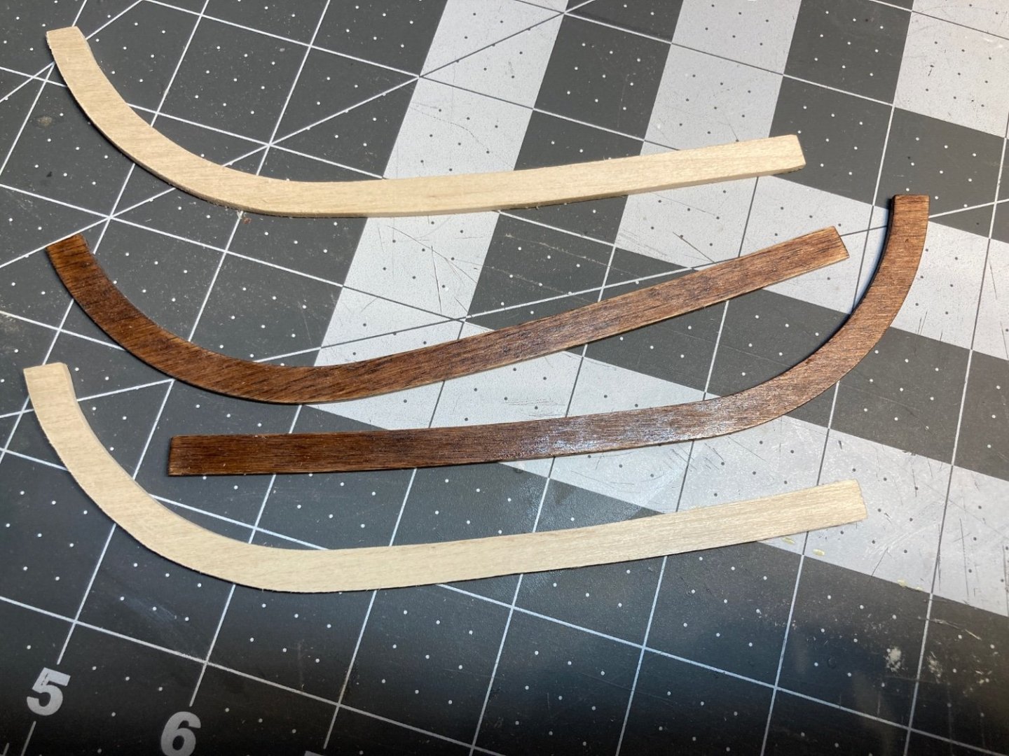
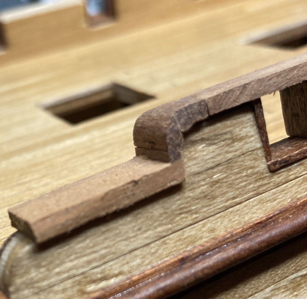
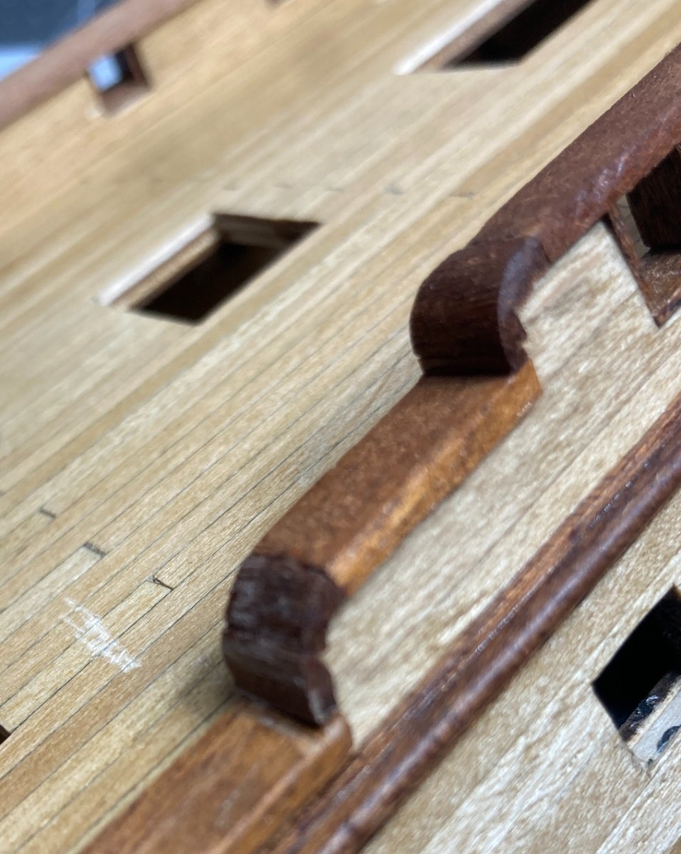
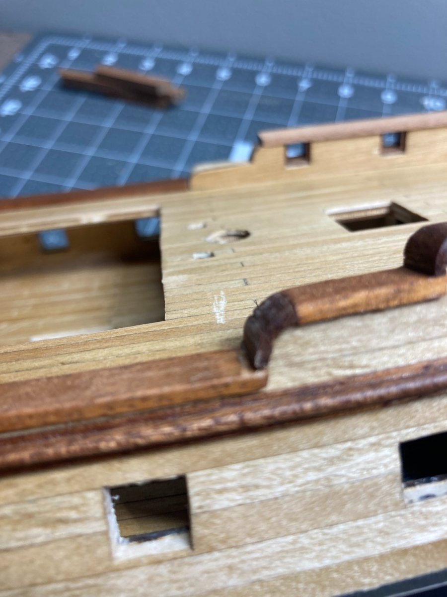
The next step was to fabricate curves that connect the different levels of the bulwarks. I used several small pieces that were beveled to fit together and then used a small file to create the curve.

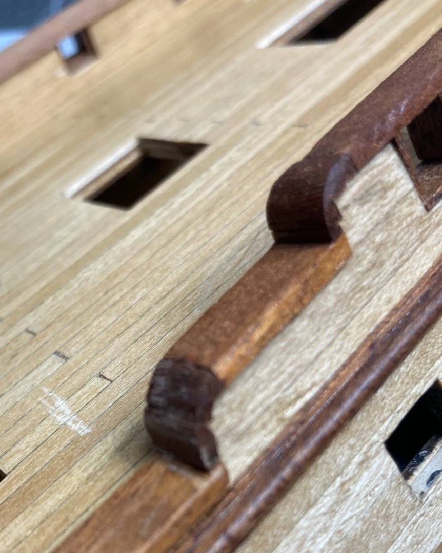

The lower curve needs a little more sanding and then two more coats of coats of shellac on all of it.
One of the reasons I chose this kit was because of features like this that require me to improve my skills working with the wood. Overall I am pretty happy with how these curves are turning out. I need to still create the two on the other side of the ship and then two more near the bow.


.JPG.7e254a626e9adee2cf3f41330bc37de3.JPG)


.JPG.25327ae35ec9aa66721b756ce9a72e96.JPG)


Run line through blocks on main top before installing the blocks?
in Masting, rigging and sails
Posted · Edited by RossR
I did on my first attempt at rigging cannons recently, but I haven't on the masts.