


Javelin
-
Posts
325 -
Joined
-
Last visited
Content Type
Profiles
Forums
Gallery
Events
Everything posted by Javelin
-
 That might have been the case, however I doubt that paint would last long on these metal parts (certainly the ones under water). They didn't have the primers and anti-foulings of today... To make matters worse, it was paint made for wood, certainly not specific to metal. Adhering to metal at sea is not for faint-hearted paints
 -
I did something similar, by accident, with clear acrylic gel. You can pull nice transparent acrylic skins off glass or plexi plates after application of acrylic gel. The acrylic is totally transparent and could be touched up with dry brushed white paint combined with the cotton. These skins are also tacky and very flexible to create a 3D effect rather than a flat layer. In any case, your rock turned out awesome!
- 174 replies
-
- 5
-

-

-
- Waa Kaulua
- bottle
- (and 1 more)
-
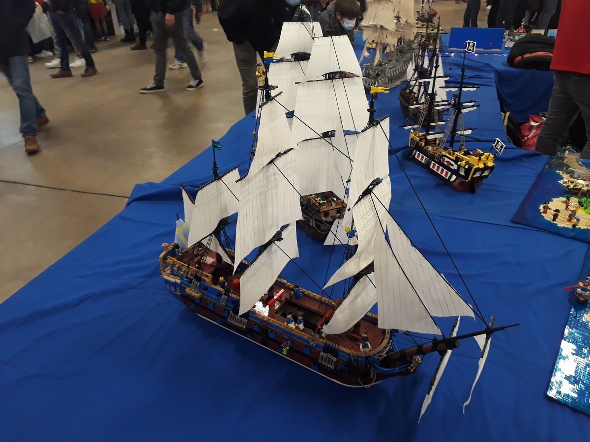
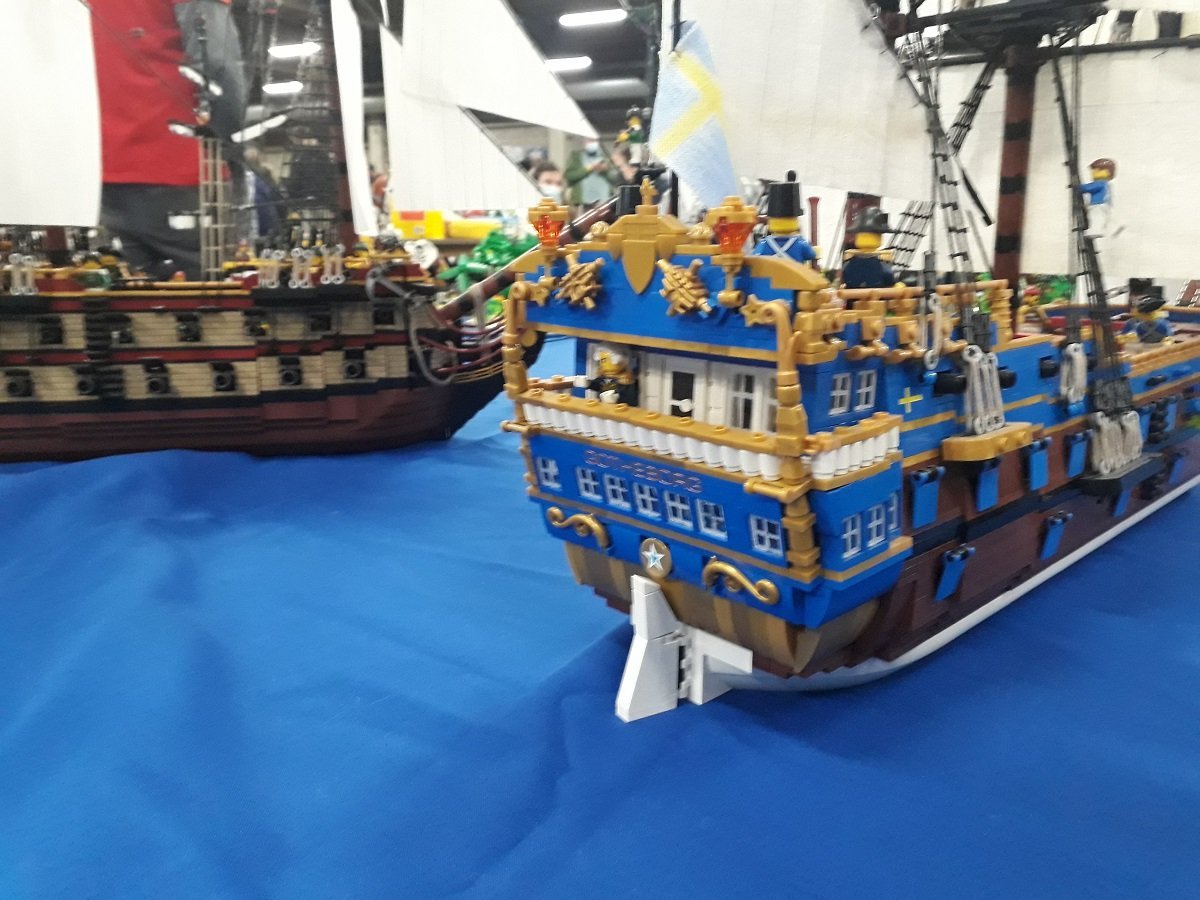
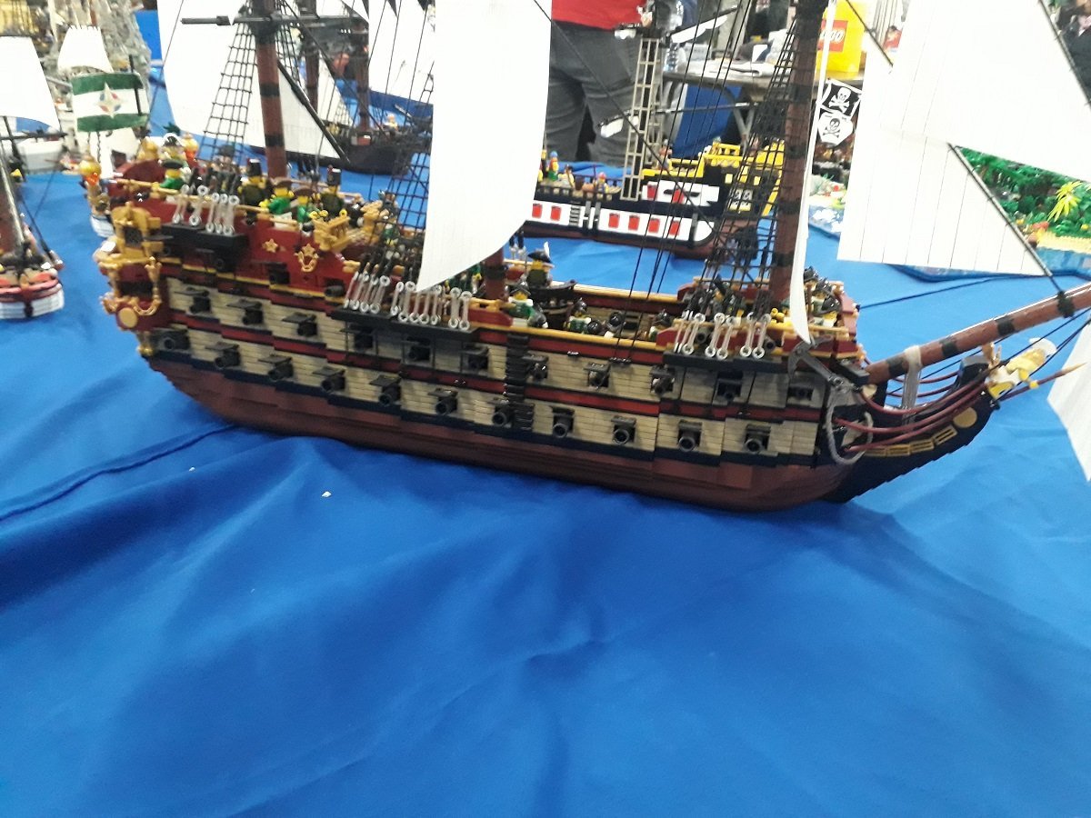
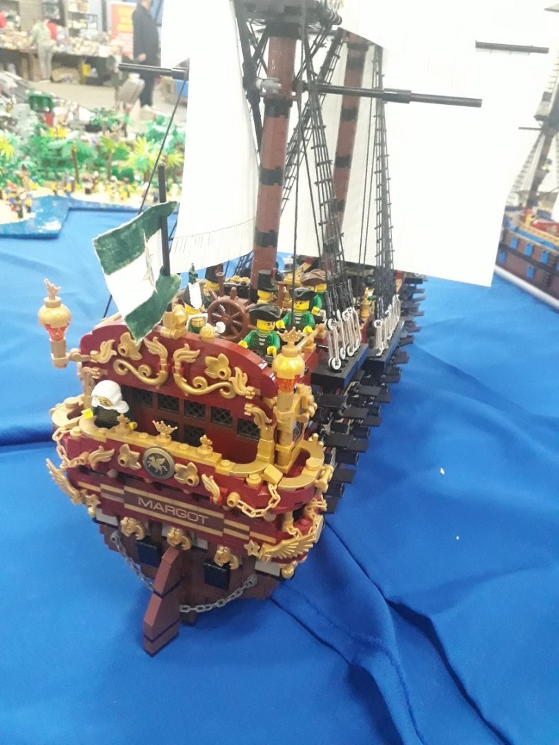
HMS Surprise by Vincwat - scale 1/69 - Lego
Javelin replied to Vincwat's topic in - Build logs for subjects built 1751 - 1800
I guess your shape is as close as you'll get considering the angle of the sloped bricks. I'd think the hull would be somewhat higher compared to the beam of the ship. Here are some pics from an event in Antwerp a few years ago. Perhaps you can gain some inspiration from these. Hadn't really studied them until I saw your topic. Unfortunately they are somewhat blurry.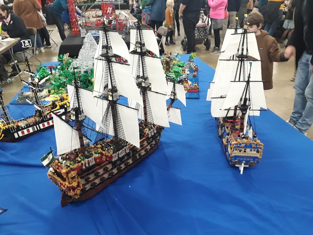
-
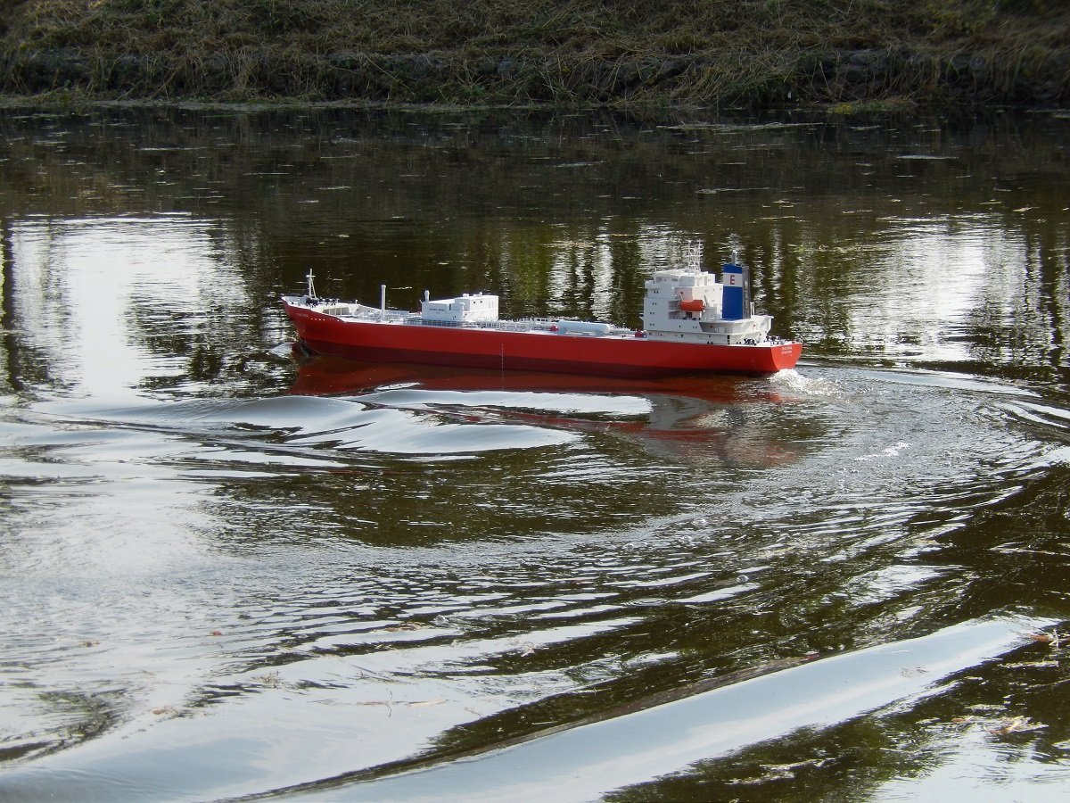
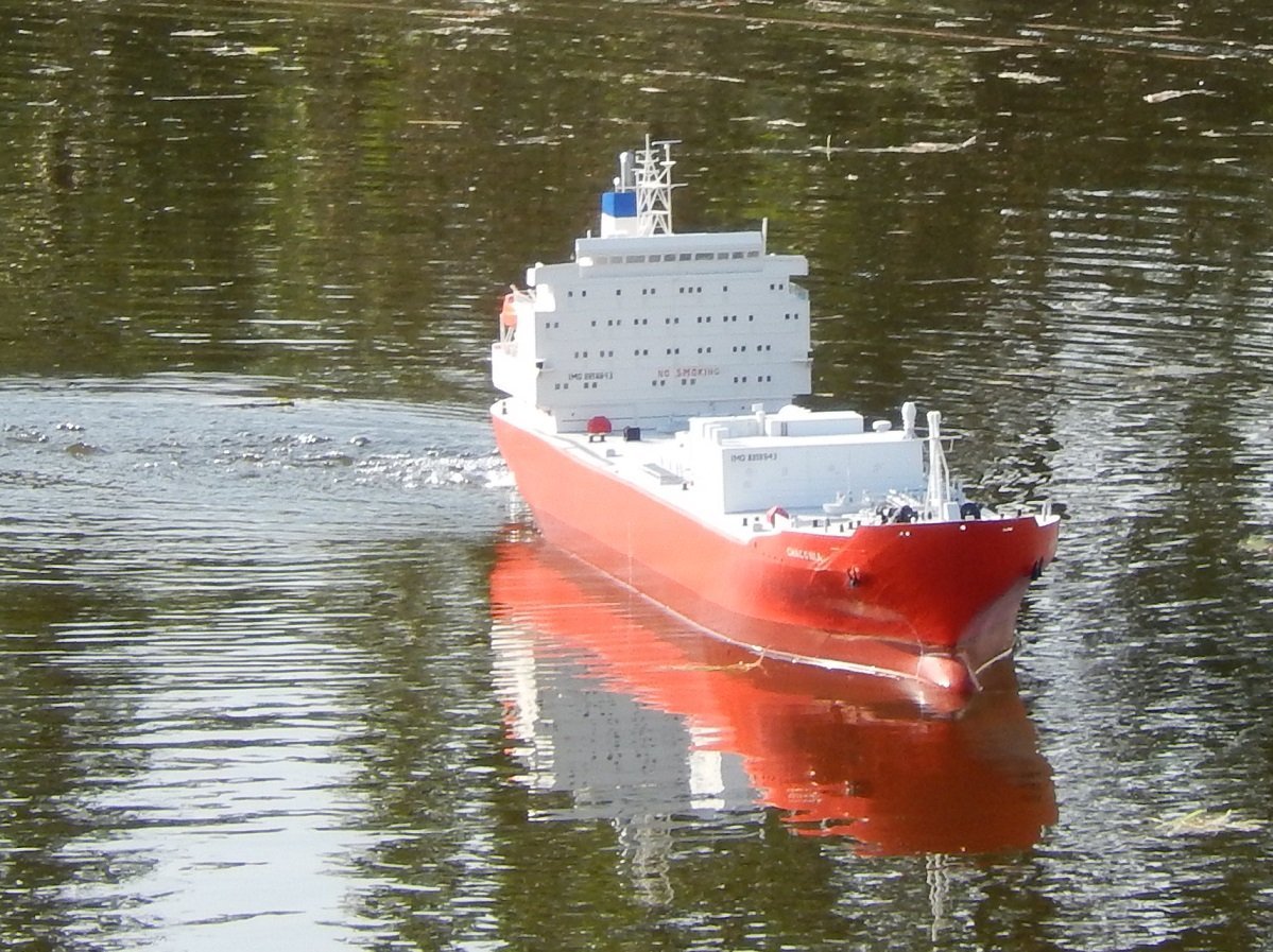
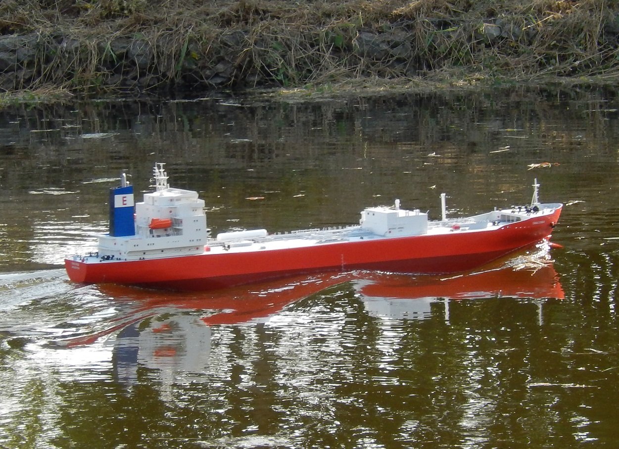
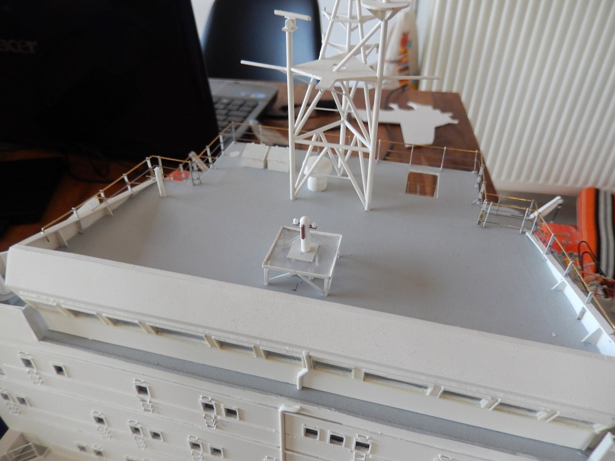
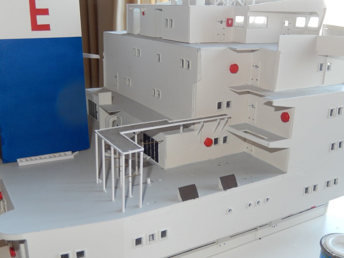
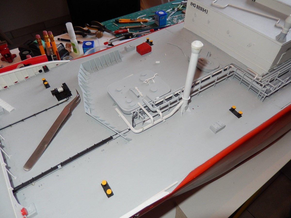
I do actually believe I was in boat #2, but can't say for certain, been a long while. I had some help getting plans and pictures from the company, so they were aware, but there is no real fixed crew on most merchant ships. It's generally a coming and going of people as holidays are shorter than work shifts, so a real rotation among a fixed group of people can't be made. We were doing 3 months (or more) on and 2 months (or less) off, so we couldn't replace the guy that replaced us. In some exceptional cases, like difficult ships, captains requested to send the same people back, and with some playing it sometimes worked to change another officer that went home at the moment your leave ended, but didn't happen too often. Only Captains, Chief officers, Chief Engineers and 2nd engineers were fixed for a period of time (around 2.5-5 years on a vessel), basically from dry dock period to dry dock period. Time for another update. One years after the last work, posted in previous update, I took her out again. My kid got a little older (3 years old), so I decided to get to the water with him. I programmed the engine and steering on one stick of the transmitter and had a "blank stick". I let him play with the blank stick, while controlling the ship myself to avoid accidents Time to get a high speed trial and some nice turns to get that battery some running time. And somehow it took me another 4 years to make another attempt at continuing. I decided to go for an achievable goal, completing the accomodation. I first built the magnetic compass on the monkey bridge. It's not very detailed, as I intended to cover it with the same green canvas as the pump motors. I also put more railing, a job I avoided before. And built the bridge wing gyro compass repeaters. I bought some 1/100 Preiser figures in a civilian outfit, hoping I could use some of them for this build. I assume this well-dressed person could pass for a captain checking his bearings. I was fully intent on completing the whole vessel at that time, but I have no idea why I actually stopped shortly after these pics. I did continue for a bit, completing that compass and gyro repeaters etc. (but I didn't take pictures of that yet), but I assume yet another build got in the way at that time? I did also construct some piping for that booster pump forrest, which helped me to tackle it this time... Soon I'll be home and I'll be back with more progress and pictures.
-
Looks brilliant and real to me! Wouldn't add any further washes to it.
- 515 replies
-
- 3
-
-
-
- Quadrireme
- radio
- (and 1 more)
-
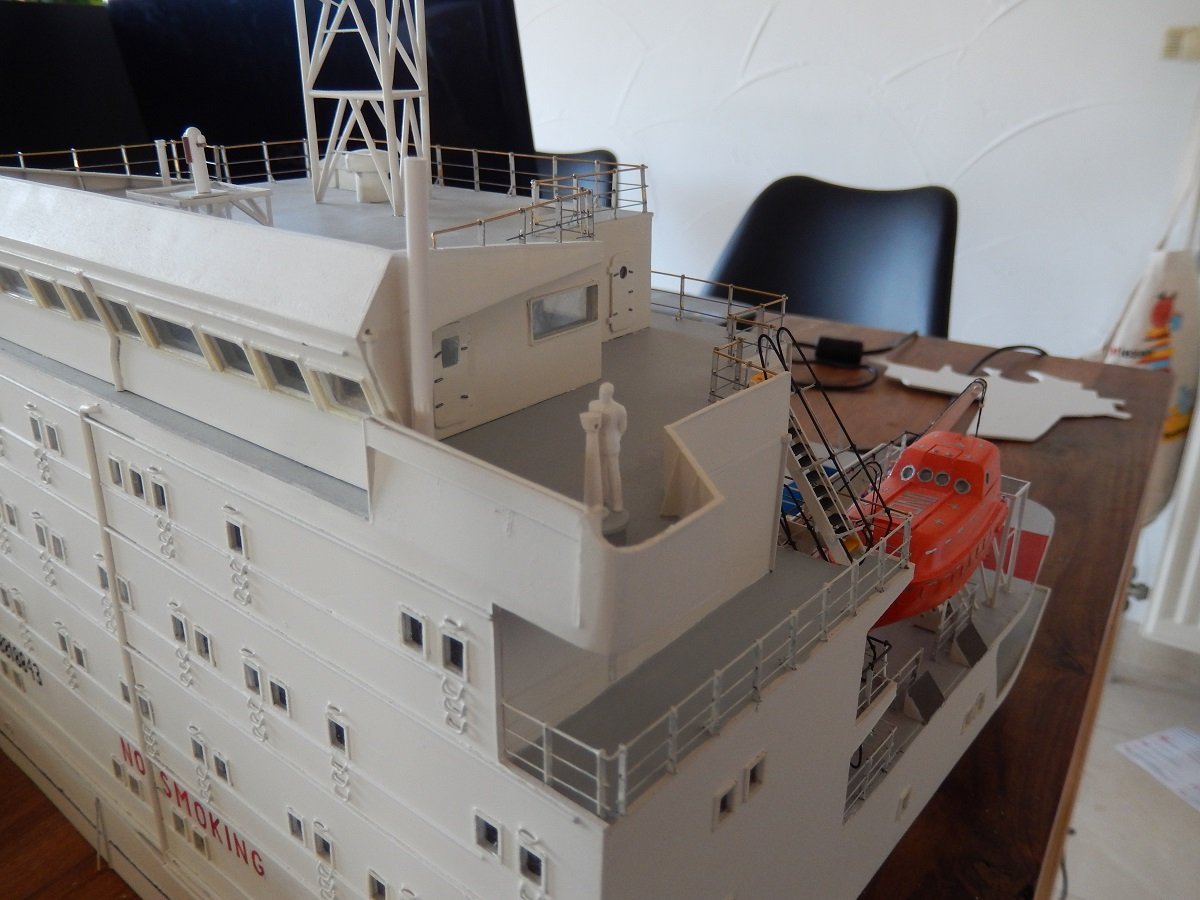
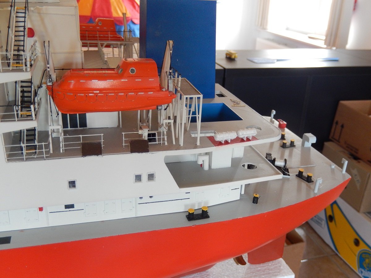
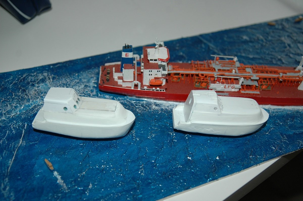
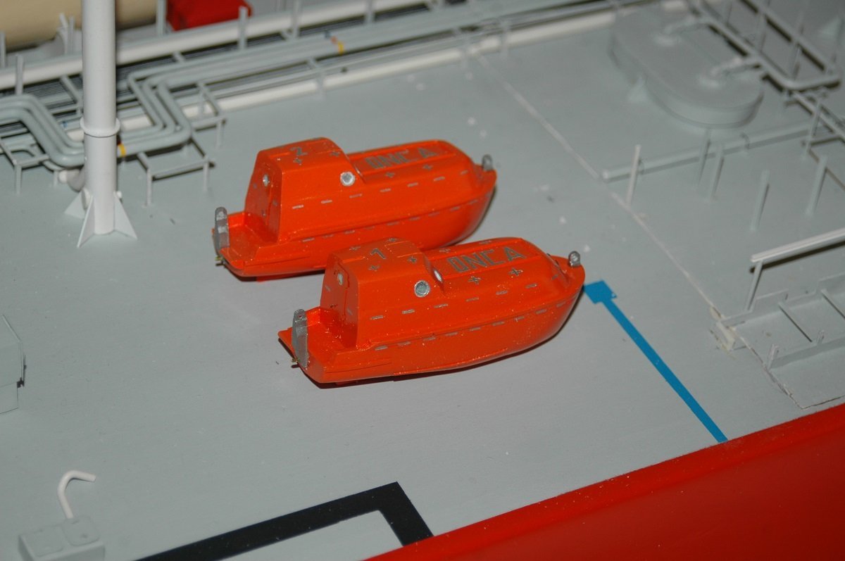
Got so caught up in Keith's Germania build (started at the beginning of that 80page long topic recently!), that I forgot to continue here. It was time for the lifeboat to go onboard. No idea why I picked number 2 first... I had kept the rigging long and open, so I could attach it to the sheaves and winches below its stowage position. As you can see, I also started adding railing to the accommodation. The stanchions are Dean's Marine merchant railing PE parts, which I ordered separately. Then time to test the sturdiness on the water before I continued with the second boat. And so the second boat got on as well. You can also see the beginning of the liferafts. You can also see the swimming pool, common for vessels of those days. It was however mostly covered with a containerized fuel tank and containerized generator on several of those vessels due to issues with the ship's generators. And in the top left of this picture you can see one of the things that killed this build... Due to slow progress on the tanker, I decided to "tackle something smaller and quick to finish", so I started a 1/100 tug called Union Eagle (it's in the Gallery). That project itself ended up taking 3 years of construction (you can see the beginning of the hull, deck and superstructure in this picture), eventually pushing me back to 1/700 builds that were indeed easier to finish within 1 year. I kept following that road for a while.
-
I'd go for the lightest of the planks Glen highlighted, the third one from the left. The darkest is indeed too dark, almost like burn marks. I figure there wouldn't be too much dirt building up. Either the crew or the sea would wash that deck regularly and at some point, all dirt from ones' shoes (which they probably didn't wear onboard) has fallen off, without much shore leave, there wouldn't be too much extra dirt coming in. Use of grease and oil was probably quite limited too.
-
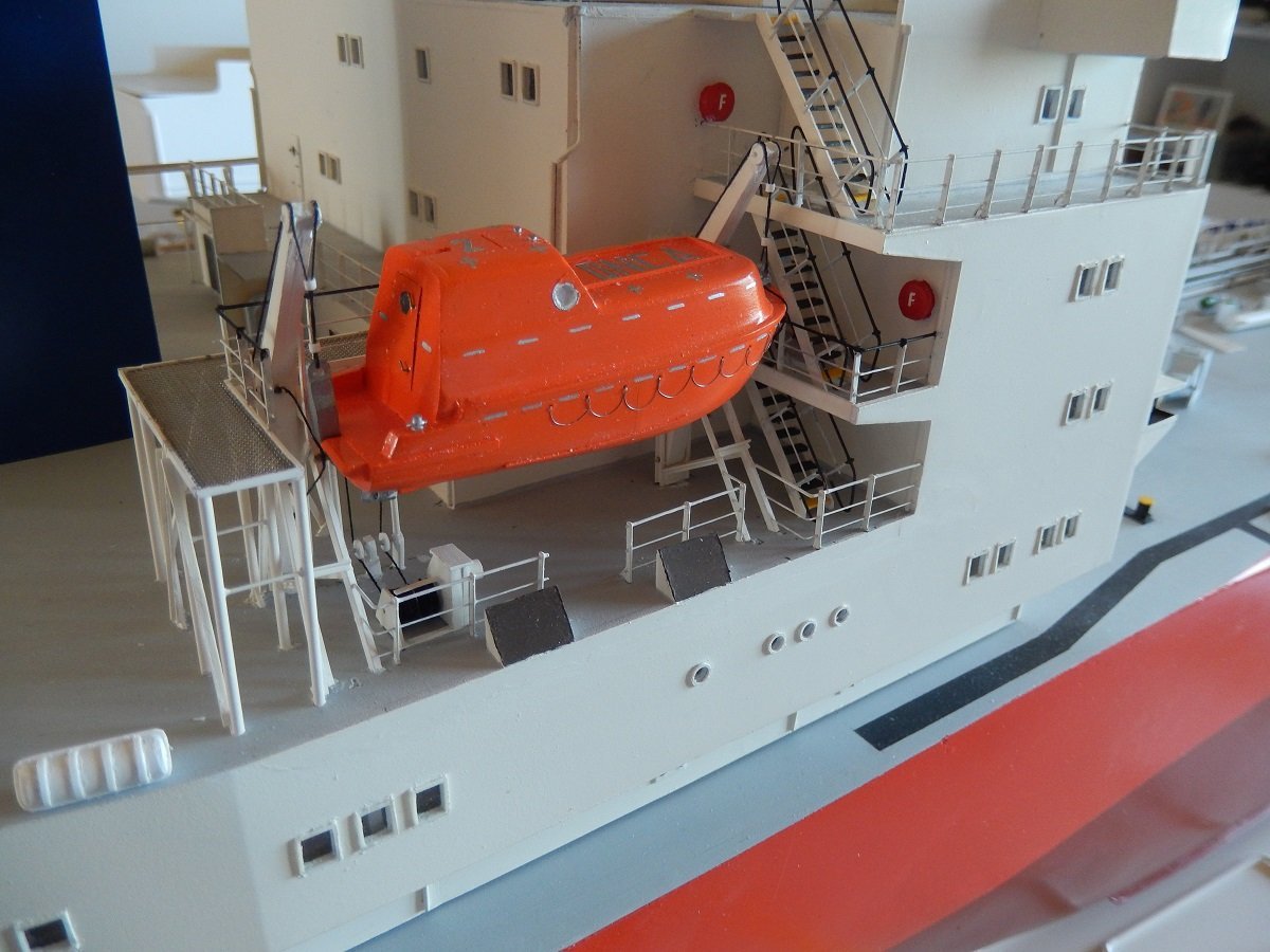
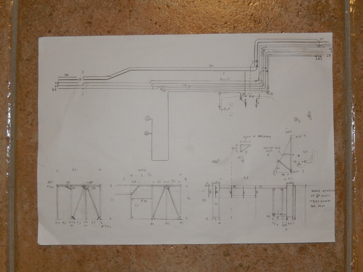
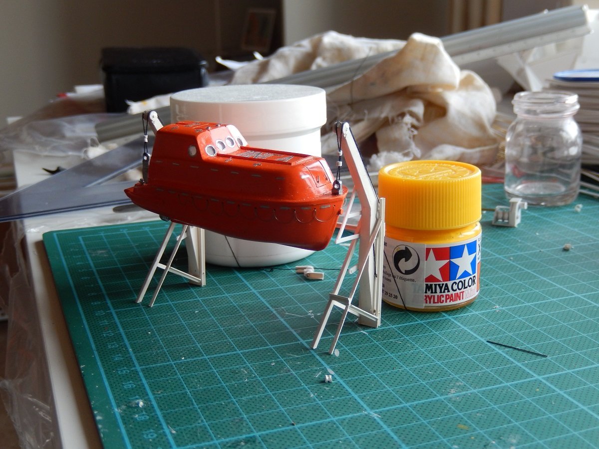
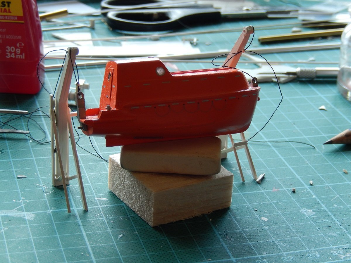
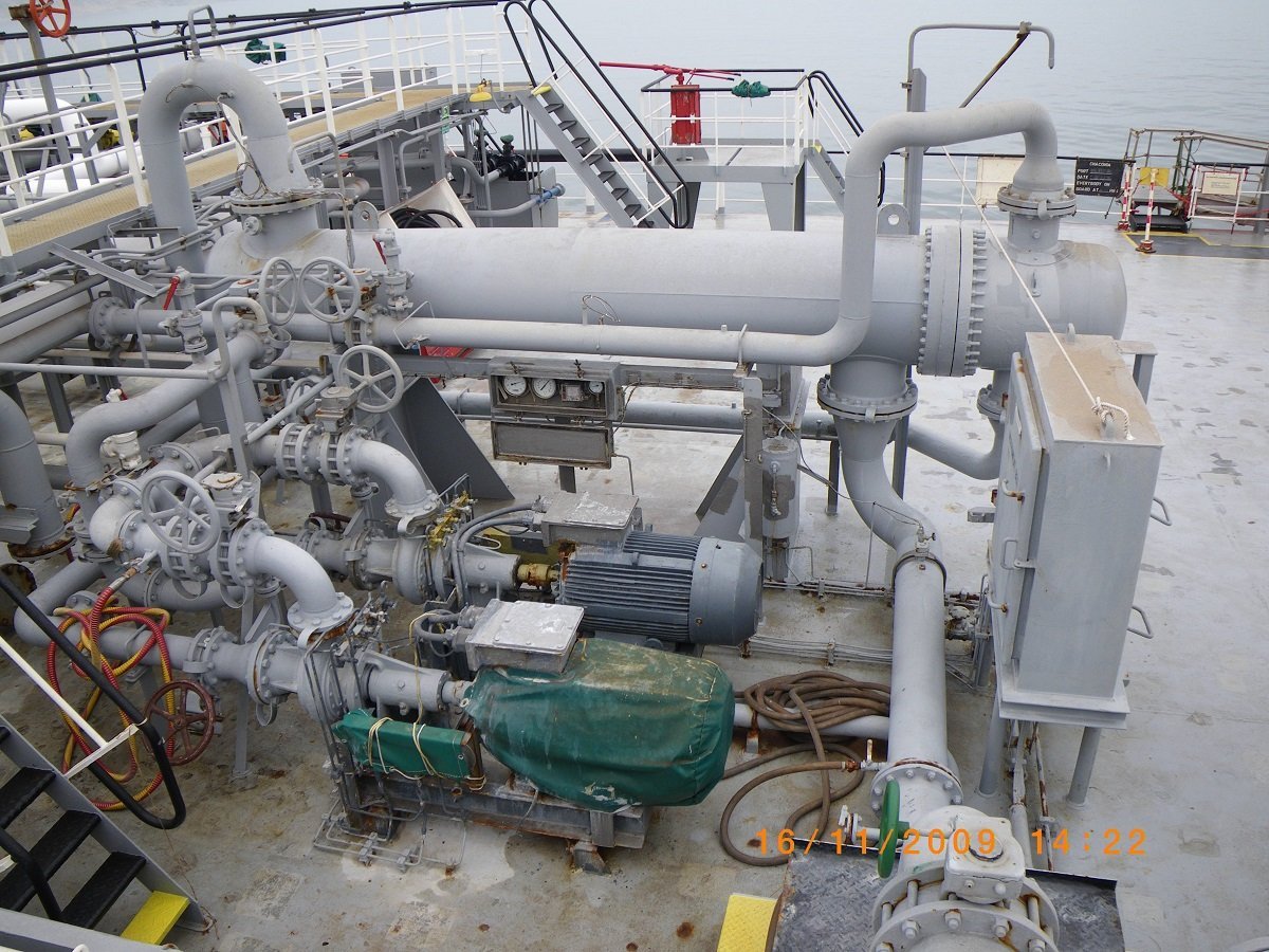
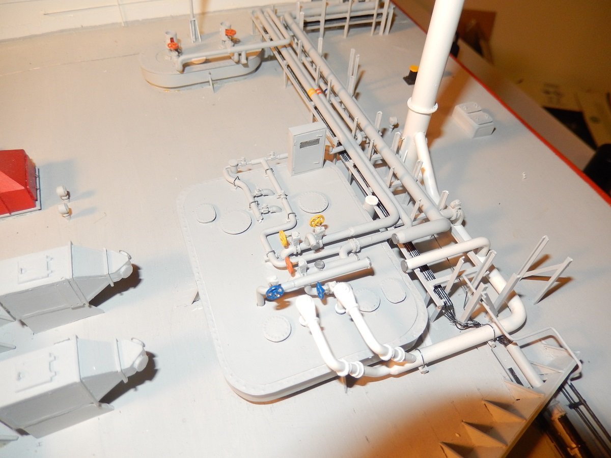
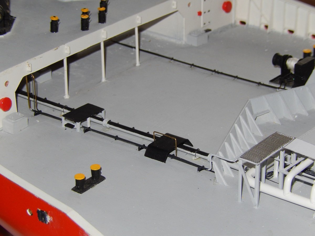
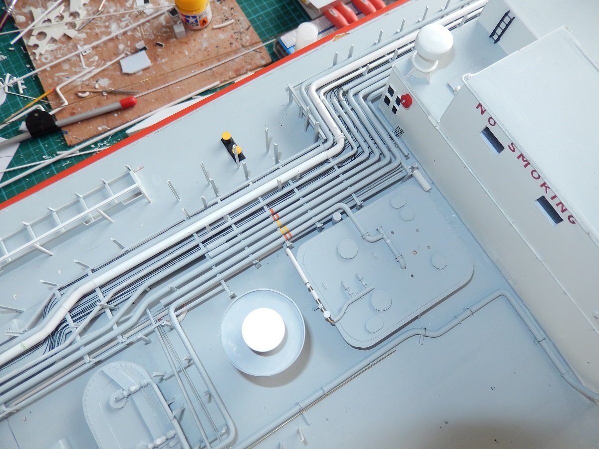
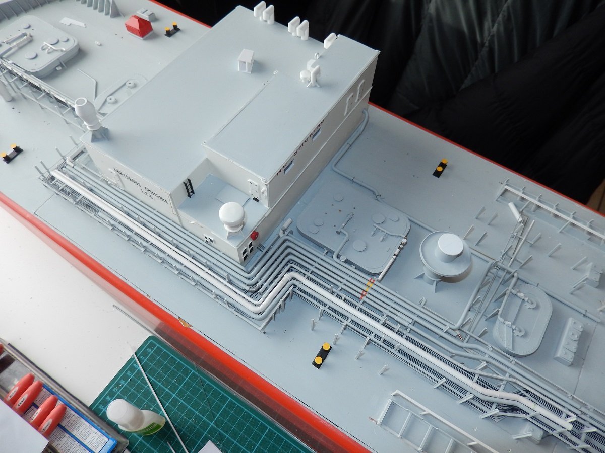
Thanks for the comments and likes. If that'd be a real plumbing job, it would have been a really expensive one... We're now somewhere middle of 2015, the year I practically stopped building. As mentioned those booster pumps were a pain... The pumps themselves weren't, but the piping to and from them is/was. The piping from the normal cargo system towards the pumps runs at deck level, however they are connected to the manifold, which is basically the top layer in the piping. All of it is built with a considerable amount of bends, this is to allow for thermal expansion and shrinkage when the cold gas goes through the pipes. That makes it of course very difficult to fit. All in all, nowadays I'm not afraid to tackle that and soon will be that moment! Here is a picture of the real deal. Both booster pumps and the cargo heater. You can imagine it took me a while to get a clear idea on how to build this. Funny enough you also see the actual motor of a booster pump and one covered by (old) green canvas. However, back to 2015: One of my drawings. I used to like making these plans/drawings, one of my most liked parts of this hobby. Nowadays unfortunately I don't get to that anymore. This drawing contains some piping, but also the catwalks for boarding the lifeboats. As you can see it has measurements on it and is drawn in scale. A lot of these details are not on plans, or very rudimentary, a combination of those drawings with lots of pictures allowed me to make these more detailed drawings. Then it was time to build those structures: And on the lifeboat side of things: Rigging the lifeboat. I didn't want to rely on actual hooks and preferred closed loops of rope through the eyes on the boats, simply because it's an RC model. Considering the weight of those lifeboats, with the epoxy filler, I doubt they'd actually float if lost on the water.You can also see the beginning of the grab lines on the side of the boat. And the whole thing rigged and standing. It's nicely balanced, so I don't have to rely on the glue alone to keep it on the ship. The small styrene loops around the rigging simulate where the double wire turns into a single chain. By moving those rings apart, it looks like a single strand in between.
-
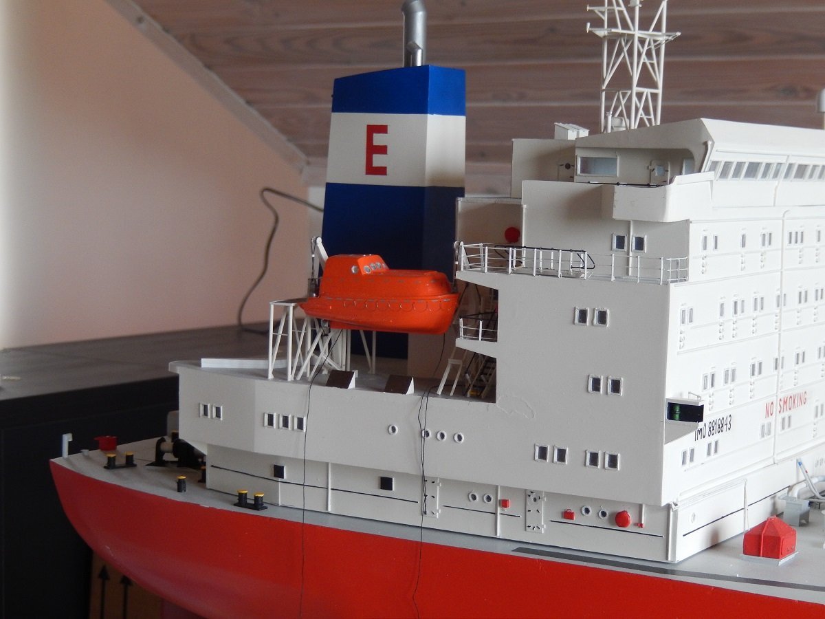
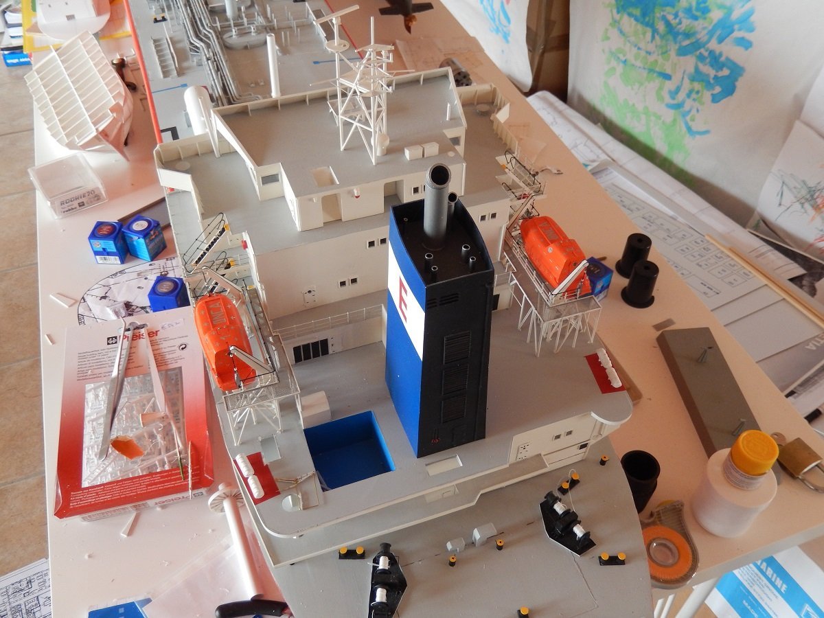
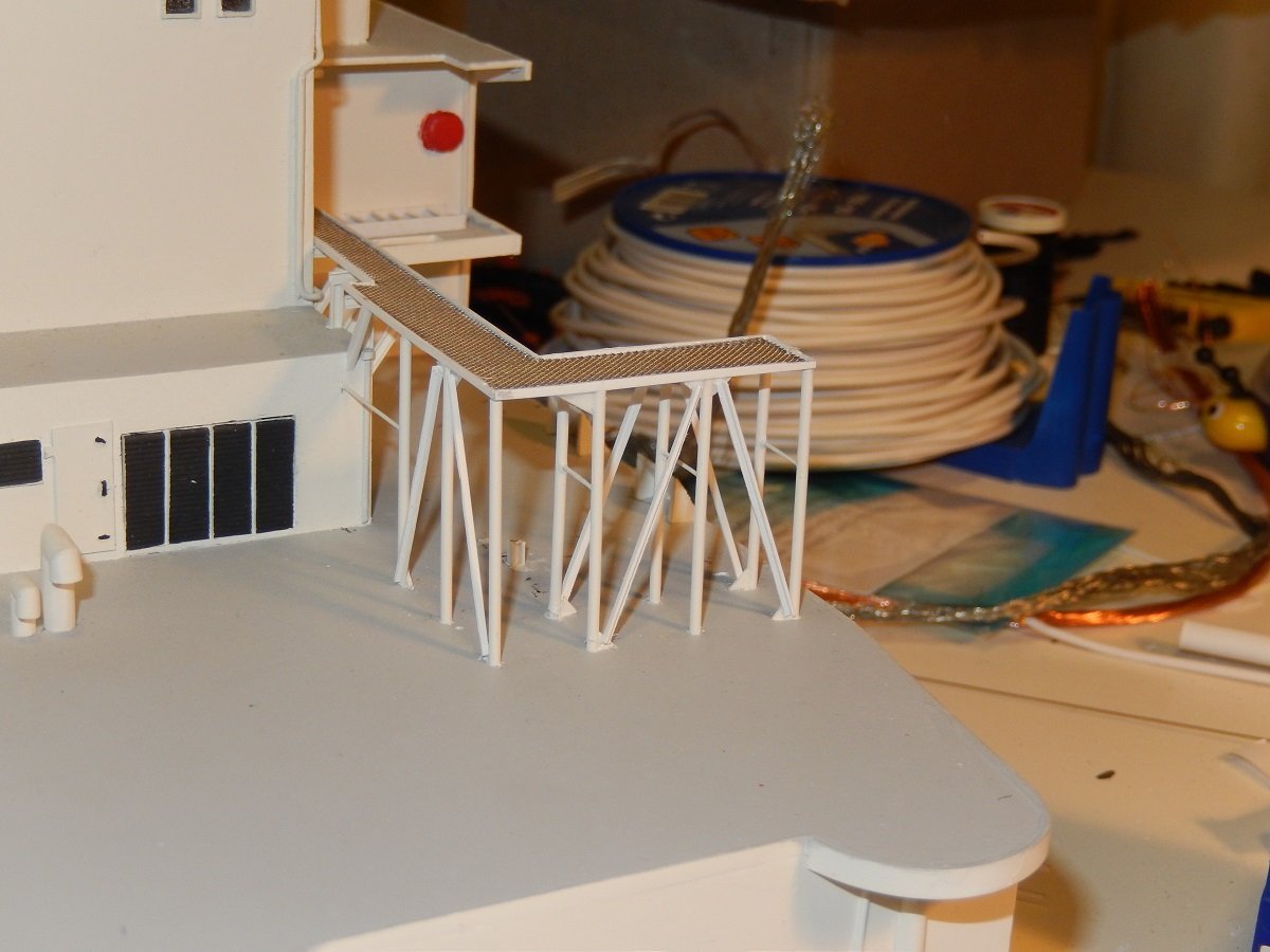
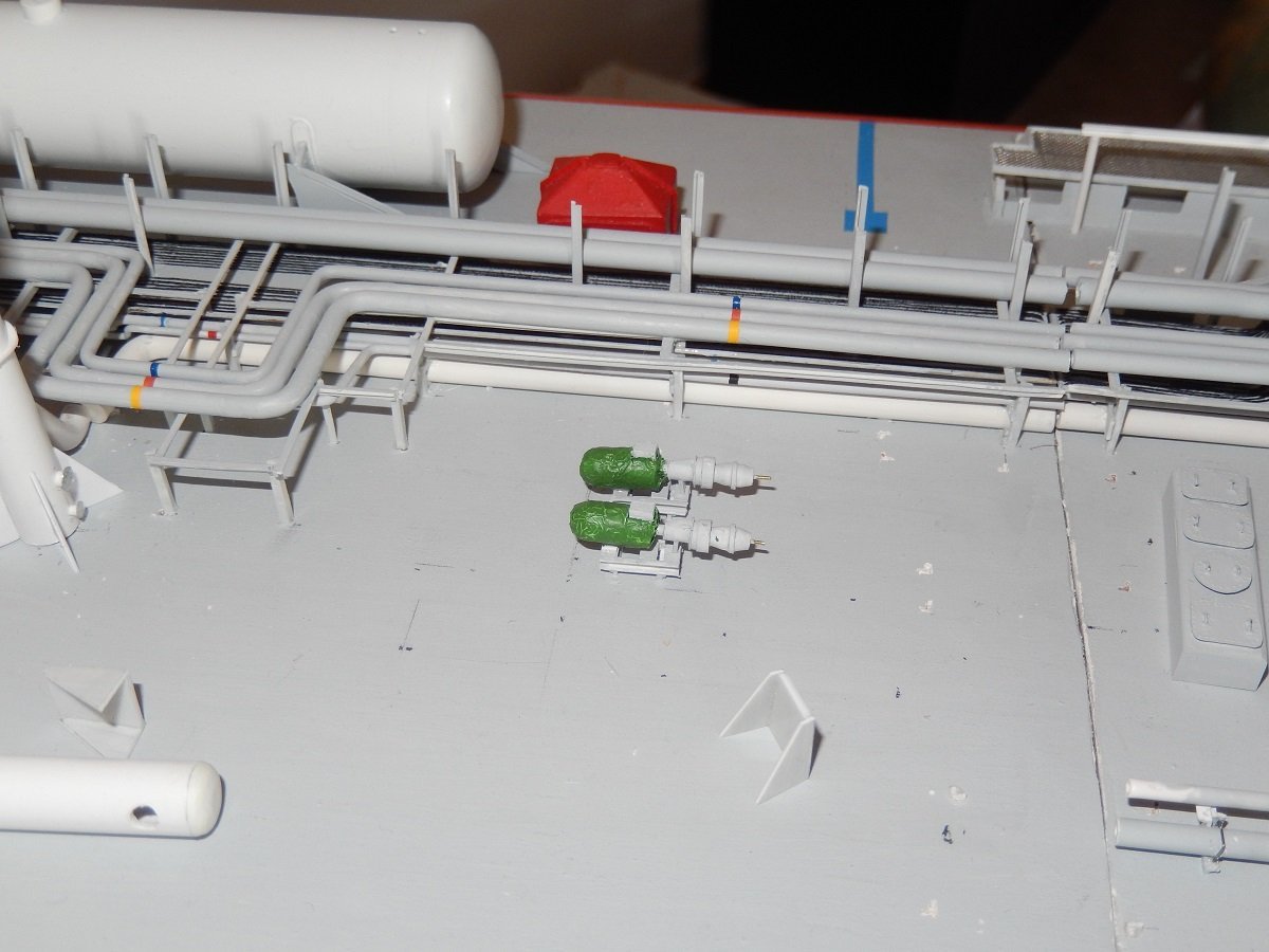
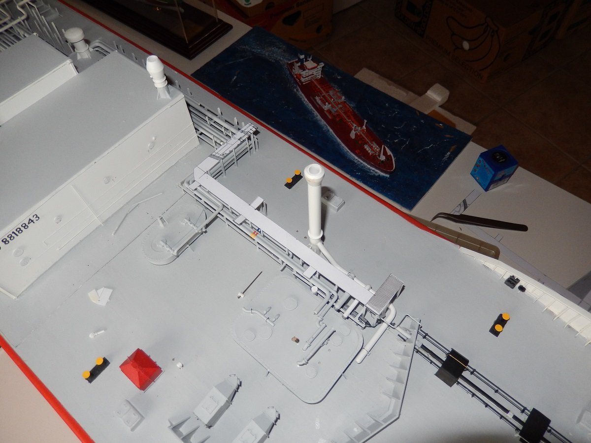
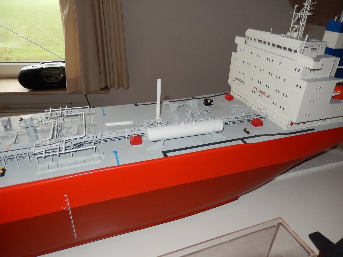
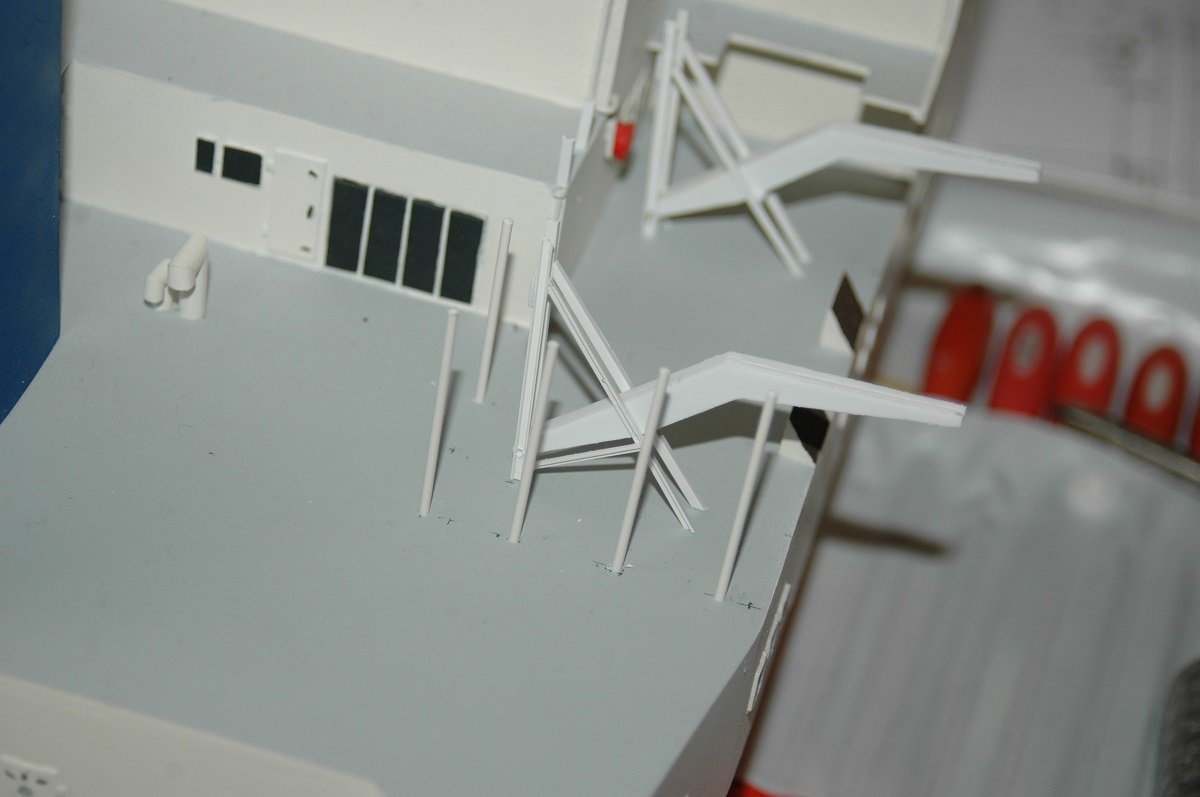
Happy New Year to all. May you all enjoy a healthy 2024. Time for another update. Seems I entered a rather chaotic phase. Since I'm near to the point where I initially abandoned it, I guess this chaotic phase was a sign of what was coming. It started with issues with the piping. I normally work from a fixed end towards an open end. Meaning that I fix the pipe somewhere, be it a pump or tank entry, and then run it towards an end where I can adjust its length, be it a bend or an open manifold end or flange. This however started to interfere with the idea of building bottom-up in layers. At some point things need to be fixed to each other. The following two objects are probably what killed the build... They are the booster pumps. Apart from regular cargo pumps, booster pumps can be put in series with the cargo pumps to reach higher discharge pressures. This can be used to pump in long lines towards far away tanks, or simply to pump into pressurised tanks. In case of the pressurized tanks, this also means the gas needs to be heated to ambient temperature, for that purpose a cargo heater is installed next to the booster pumps. The beginning of that cargo heater you can actually see laying around in pictures in the previous post and in following picture in the left foreground. To finish that part of the cargo system, there is a separate high pressure line towards the manifold as well. On these ships you could only put one booster in each cargo system, or both booster pumps in parallel to each other. On other vessels occasionally you can also line up the booster pumps in series with each other, so basically making a series of 3 pumps to achieve even higher discharge pressures (at a cost of flow rate of course). When at sea, the pump motors were generally protected by green canvas, which is what I replicated here. I didn't really find a way to build the regular electric motor cooling fins and structure, so I decided for a general shape and then covered it in alu foil, which I then painted green. I then made some catwalk platforms for the compressor room/ deck house. As well as the lifeboat embarkation area. I needed to do that before I could mount the lifeboat davits. And then I also started thinking about finishing the accommodation. So I added the navigation lights. As usual placed in a very convenient place, easy to reach and replace the light bulbs (NOT!)... I've never really seen a ship where it was easy to get to these things. They always seem to be the last thing they add to a ship design without giving any thought to the fact that you have to replace those bulbs (quite often really). (but since I'm not an electrician, this wasn't really my problem 😄)
-
Happy New Year Glen, what I meant was that your stone/rock looks somewhat bland. It's side is too smooth and even, an effect you'd get when the water would run down its surface continuously. In the waterfall pics you don't see smooth rock, it's not eroded by the water as the water touches the rock in only a few places on its way down. The rock itself however is broken and worn by gravity with a high frequency of sharp edges. I believe you could either adapt your rock with more protruding pieces, like the one you circled, or try to replicate those edges by fine dark jagged lines (combined with lighter areas above them) to break the large grey areas on your rock. The jagged lines would then insinuate shadows and cracks in the rock. That's just my view though, all in all the centerpiece remains the bottle and the falling water would hide and break the view on the larger grey areas of the rock after all...
- 174 replies
-
- 5
-
-
- Waa Kaulua
- bottle
- (and 1 more)
-
That's right. I also believe you need ridges. It looks somewhat out of scale at this moment. The small ridges will scale it down I believe. Apart from that, gorgeous work so far! Even without the rock, the bottled ship looks awesome.
- 174 replies
-
- 6
-
-
-
- Waa Kaulua
- bottle
- (and 1 more)
-
With regards to bow thrusters, normally the propellors turn in the same direction, but the thrusters are mounted opposite in the tunnels. So one will have the propellor facing portside (motor or gearbox SB) and the other opposite. Not sure with a 4-prop arrangement if the'd go 2-2 or 1-1-1-1. This is done to avoid the offset of such thrusters. When running on 0-force they do push a little to 1 side, so by reversing the installation with 2 or 4 thrusters they cancel each other out.
-
I had a further look at the ship and think I know where you got that. The three markings on the hull, where you located those thrusters are actually signs to show tugs where they can push. They're not thruster marks like on the bow. She doesn't have stern thrusters neither, since the azipods can be used sideways aft.
-
I have serious doubts about those 3 thrusters you put in the center body. Did you see that on pictures somewhere? Doesn't make much sense. In a normal case they'd just put stern thrusters in the skeg aft, just forward of the azipods. Through the body of the ship, with extremely long tunnels, probably doesn't work. You also wouldn't want that kind of noise on a cruise ship in such a location. All side thrusters create quite some noise when in use, not a huge problem near the bow or stern, but spread out like this... The stabilizing fins are also likely angled downwards a bit, but may be correct after all. Some dry dock or construction pictures of these ships should be available somewhere.
-
Work of a true perfectionist. Great results. I am impressed by you attention to the hull planking and your patience in achieving its perfection.
-
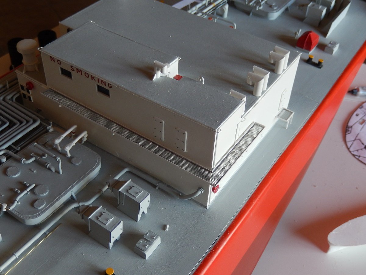
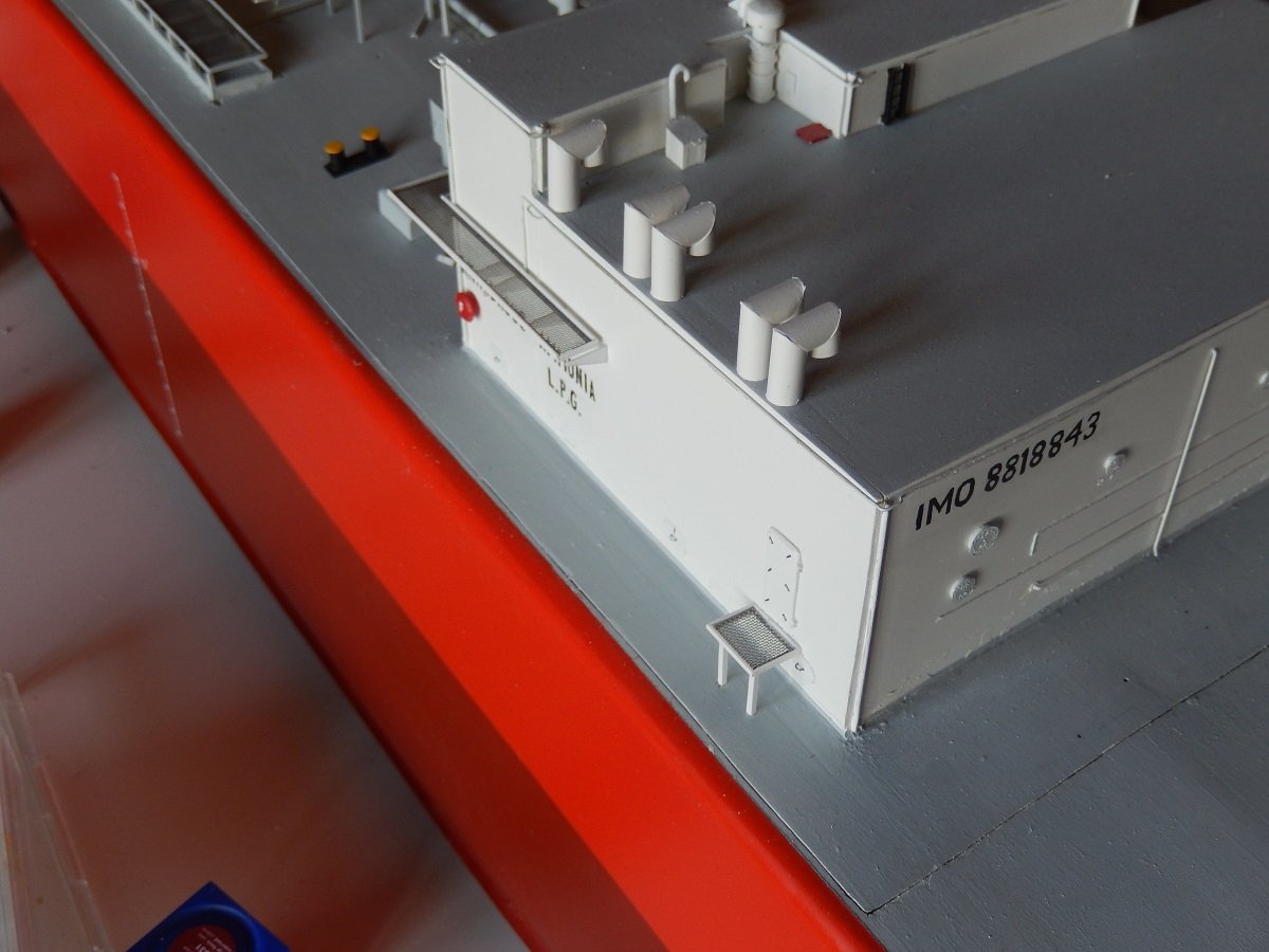
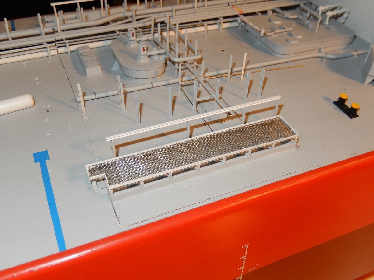
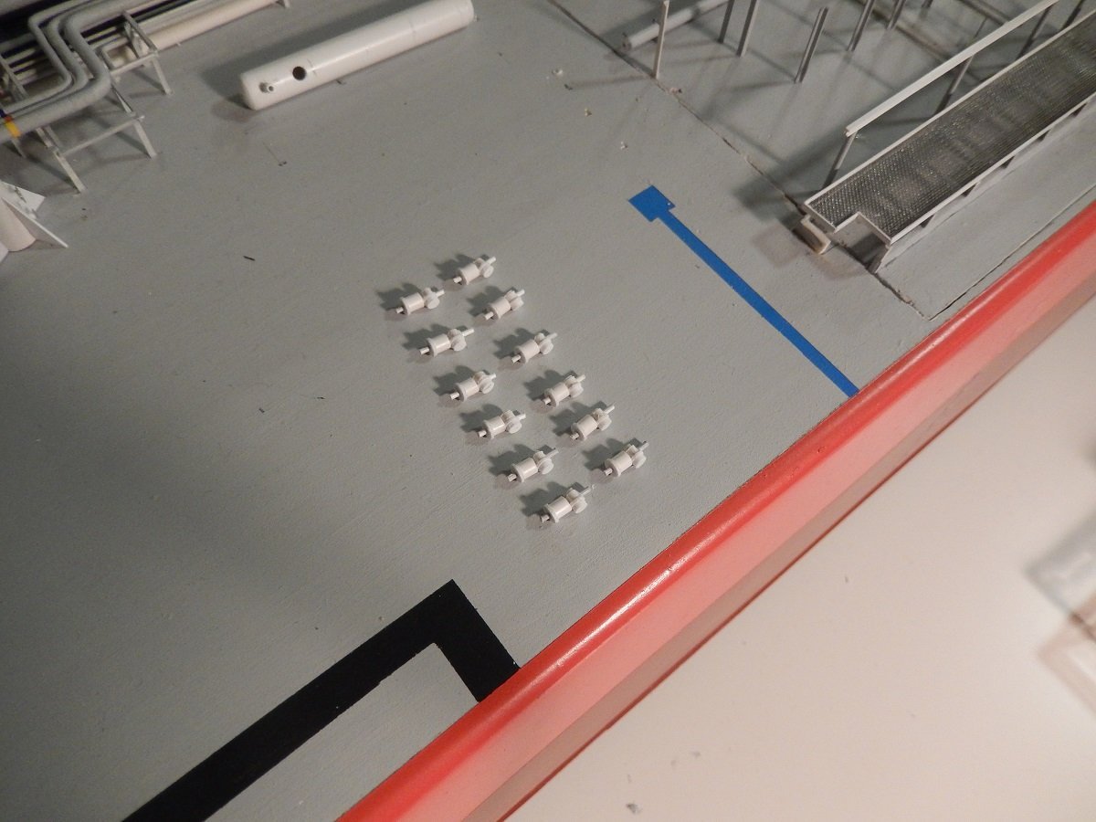
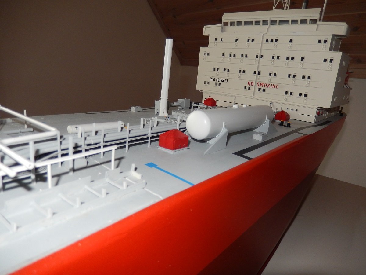
Thanks Jerome, indeed, all the extra rules and requirements did improve a lot of things onboard. First of all Merry Christmas and a Happy New Year (in the near future) to all. Although I fully understand the order of things seems rather chaotic, you have to remember this was built over a period of years and with 3-4 months periods in between. The big downside of those months at sea was that each time I got home, I had to figure out where I left of and what I was planning to do next. I guess after the deck tank, I decided to go for some finer work and finally finish one of the tank domes, starting forward. This would practically get the forward part of the ship finished, apart from some minor jobs. I bought some metal cast wheels from Dean's Marine for this. They're somewhat crude by today's standards, but I guess that's not so bad, considering it's a Radio Controlled model. No flimsy PE for this type of ship. They of course follow the same color code as the piping, so that you have a last warning when you're about to open the wrong valve . Then there are the "drip trays" to contain leakage from the manifold (where ship's pipes are connected to the shore pipes (or other ship's pipes) for loading and/or discharging. I built those a while back, with the "bright" idea of making part of them cover the seam of the hatch. As mentioned before, not a bright idea at all. However, this part could work, I just need to make it sturdier. Over the years it has been hit (slightly) or touched during construction and some of the supports have come off from underneath the grating. I guess I built it too true to reality without enough thought on the strength of it. I'll probably redesign it a bit to make it sturdier. One of the last details on those valves/pipes were the hydraulic valves. Some shut-off valves were automated, even in those days. This was by requirement, when a high level was reached in the cargo tanks, the loading valve of that tank would close, if for some reason the level kept rising to high high level, the manifold valves would also close and a signal given to the shore that stopped their pumps. Often through a pneumatic hose connection that triggered a shut-down when it lost pressure. This pressure loss could by caused by hose rupture or by pushing buttons that released pressure from that line. In any case, each liquid and vapour line had a hydraulic actuator on each manifold and each tank also had its own hydraulic actuator on the loading valve. Behind each one of those was a manual "double-shut" valve to avoid issues due to single valve leakage. I made those actuators long ago, I hope I made enough of them. These valves were really basic, opening by hydraulic pressure, closing by release of the hydraulic pressure and disk springs located in the big cylinder. I remember lots of issues with leaking packings and broken disks inside. The timing of closing was very defined to avoid pressure surges in the line when the valves closed with running pumps. Unfortunately this closing time had to be adjusted each port as it was dependent on the release of the hydraulic oil when the disks closed the valves and hydraulic oil runs a lot easier in hot areas than it does in cold areas... One of the issues I've encountered with such mass produced parts from long ago, is that I often seem to have either lost some of them or not made enough of them. Since it's so long ago, I forgot how I constructed them, so I need to figure out how I did those etc. I hope this will not be the case with these valves.
-
.....and flightless. Great to see her bottled. Merry Christmas and a Happy New Year!
- 174 replies
-
- 6
-
-
-

-
- Waa Kaulua
- bottle
- (and 1 more)
-
Spartacus by Javelin - 1/2000
Javelin replied to Javelin's topic in - Build logs for subjects built 1901 - Present Day
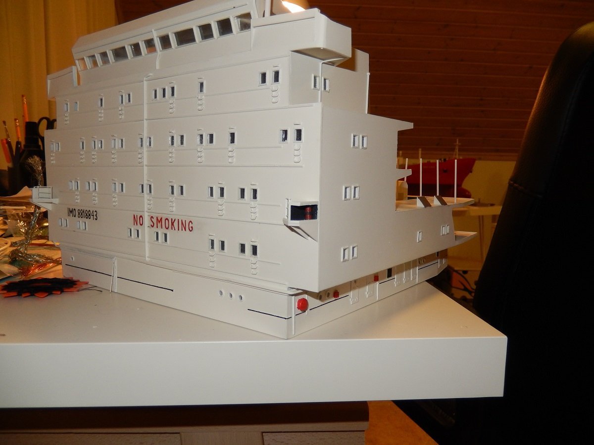
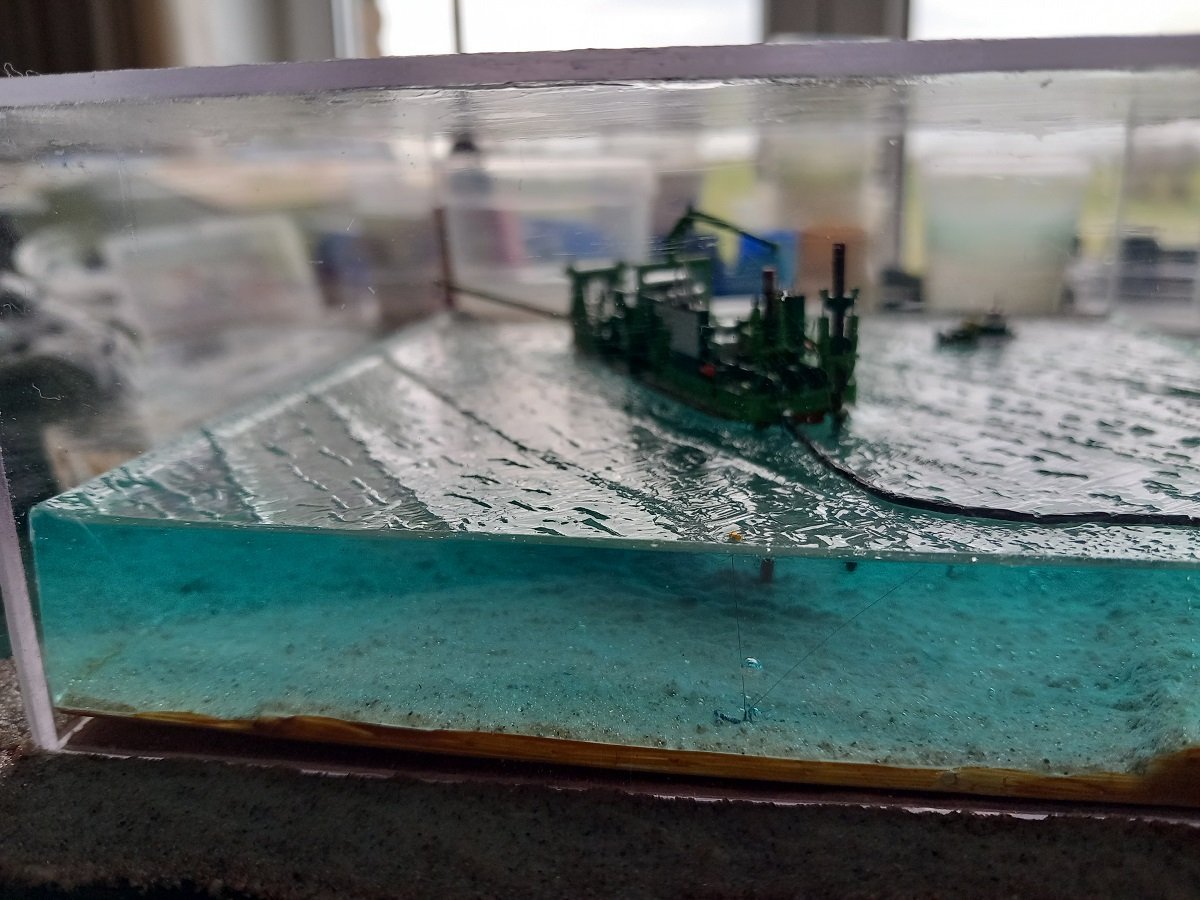
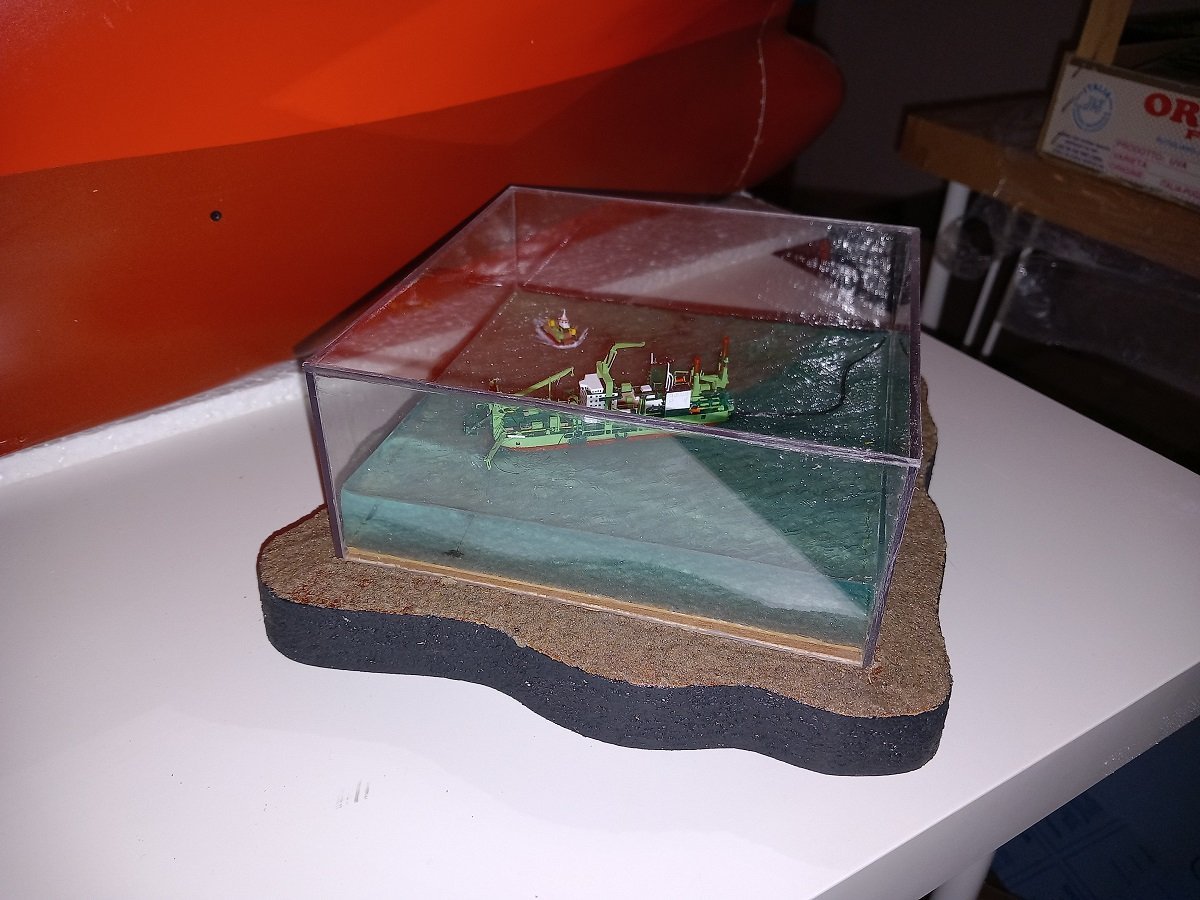
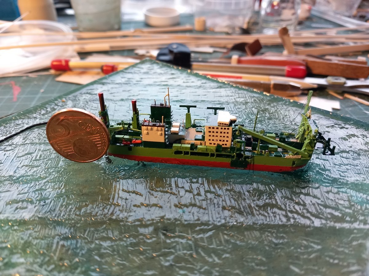
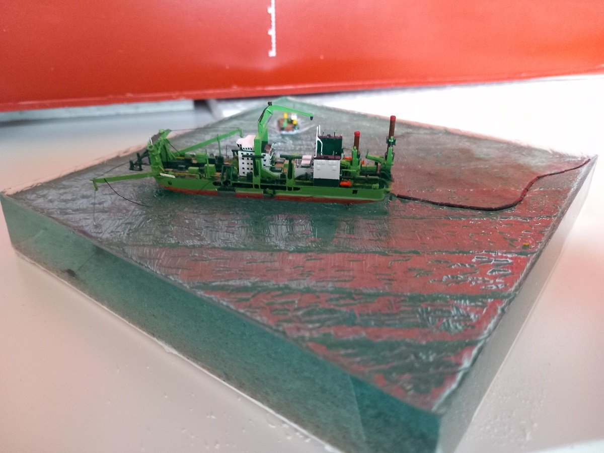
Thanks for the comments and likes. This one is running to an end. Although it started as a bottle build, which, in retrospect would probably have ended in complete failure, it is still a project for my son. I therefore needed to make something solid as a base and protect it, you know what boys rooms can be like... I'm not necessarily happy with this base, but I kind of took what I had available, taking into account that it needed to be sturdy and heavy, capable of taking a hit of I-don't-know-what-he-can-throw-around without immediately flying off the shelf. It's not the first case I made of the transparent Vivak plate, but it will be the last one... I probably don't have the right tools to handle this, but all in all it's a very tough material to work with. Cutting is extremely hard, scouring it with a blade, pressing it and snapping it over an edge certainly results in cracks and it's difficult to glue (only MEK seems to work). In the end it will serve its purpose of keeping dust away on top of some shelf. It's also not a top model, as I'm still heavily annoyed by the air bubbles. I was also thinking of making a small cutterhead model to place in a corner outside the casing, but I'll first see if he would want that or not. Additionally you can see the base of the dio was bent. I'm still not sure what caused it, I'm pretty sure it was still straight after the application of the sand-acrylic mixture, but I'm not sure whether it was still flat after application of the pure acrylic gel over the sand. Could also have been caused by the epoxy I guess. Another lesson learned, take a sturdier base (for example a glass bottle) if you want to use epoxy. That said, I've painted the edges ochre and will put panels outside the casing, following the contour of the diorama inside and then work up to those plates with acrylic-sand mixture to make it look like the bottom continues outside the casing. This will then also hide the bent base plate. While I'm at it, I might also drop some of that sand over the black sides of that base plate, again following a curved pattern, but I don't consider that strictly necessary. It'll also get a nameplate, still considering making it flat on the base, following the curves, or screw in a flat, sturdier name plate, some distance off, just touching the curved forward side of the dio. Here you have a better view of the neuring buoy of the floating line. Unfortunately one of the air/gas bubbles attached itself to the line, completely screwing up the effect 😭 You also see the bent base plate.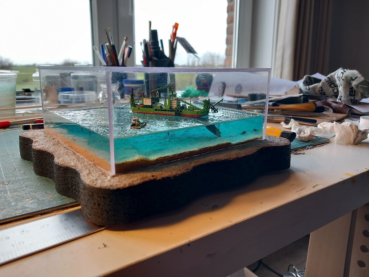
-
Great job on this build Phil. Good to see an old project like this being finished, and with such great care! Showing something practical/operational like the anchor handling is always a plus in my book! Love the pose and face of the guy in post #212
-
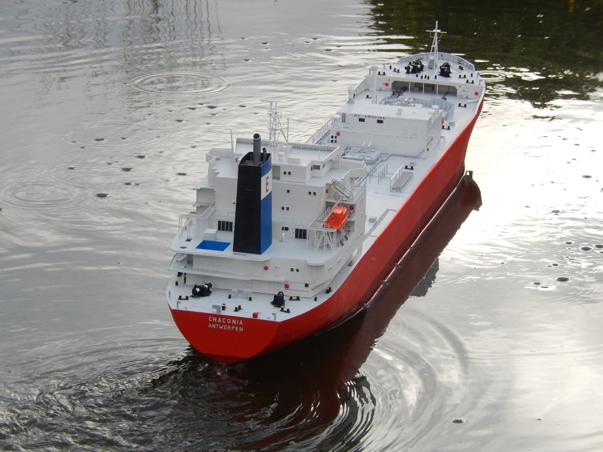
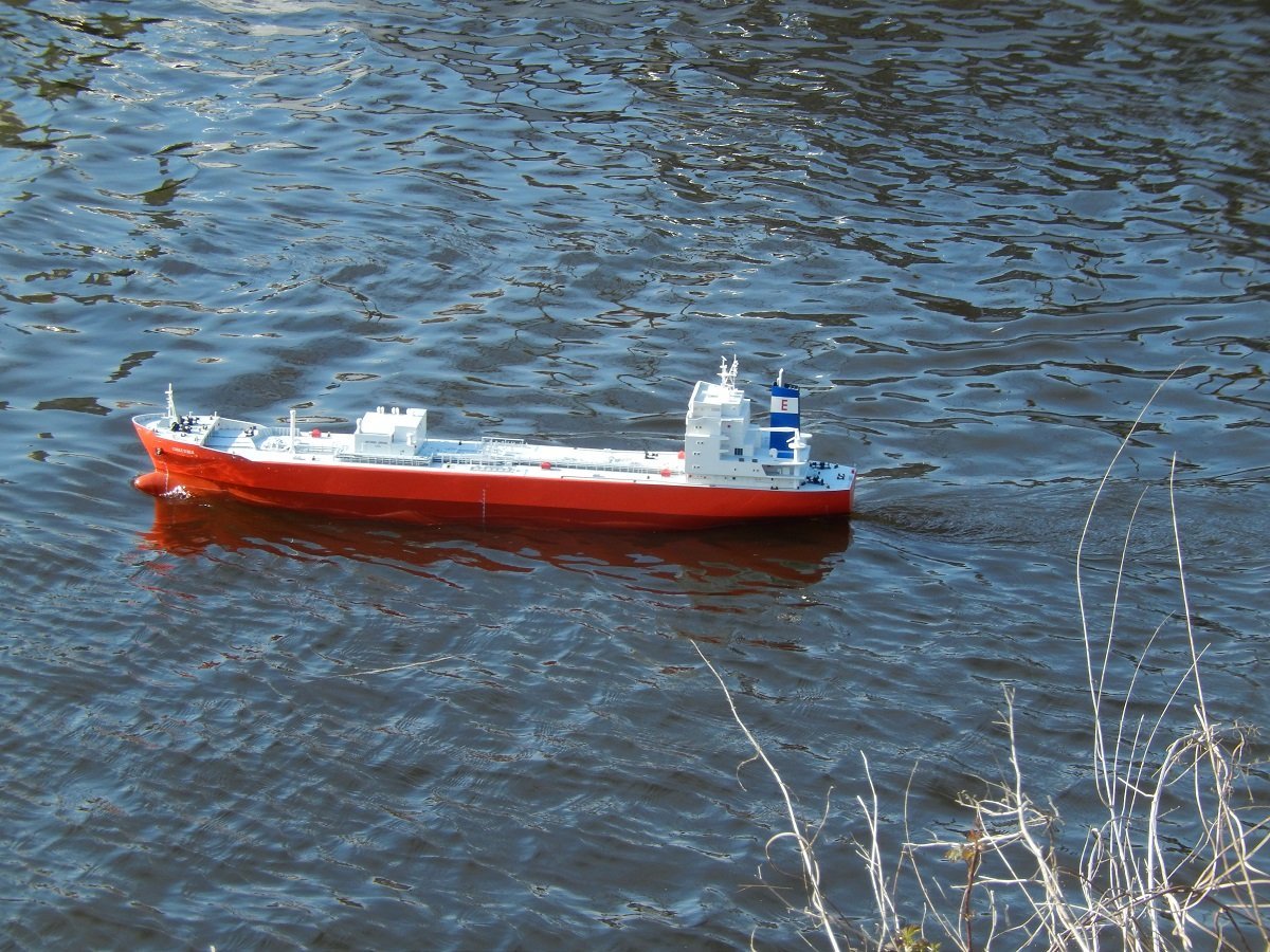
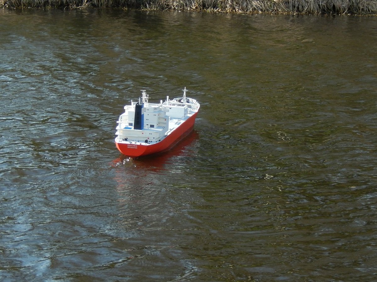
I didn't respond to this message yet, sorry for that. I wouldn't say "definitely" as it's quite normal to sail in conditions like this. Ballast volume (and weight) on those ships doesn't match the cargo weight. In a ballast voyage you take into account your stability, longitudinal strength and full submerging of the propeller in account (the latter is something that can be played with to enter certain shallow ports if required). There is also a minimum bad weather draft forward to avoid excessive slamming, but that's quite a shallow draft too. In the end you try to take as little ballast as possible, since all the additional weight causes additional draft and therefore drag. This results in higher fuel consumption. You can also adjust the amounts during a voyage, depending on the weather or required arrival condition. You can also see how high she is in the water in the pictures @Valeriy V posted in the first page of this topic. As mentioned my "normal" sailing weight is 22kg, which equals 22.000t displacement in reality, which is approximately correct for the real vessel (in ballast of course). Full load she should be around 30-31.000t (I have the exact numbers somewhere), which would equal 30-31kg on the real model. I will of course increase the weight in a later stage, just to see it on the water like that, but that will likely also drain her battery much faster. I do believe her hull is strong enough to carry this amount of weight. From my files it appears I left the lifeboats for a while (I'm thinking because I was in search of a good method for the grab lines, but it might also have been to split up the tedious piping job). In any case, I did continue with piping and other detailing. The construction method of the catwalk above the piping. This is a safe access to the bow during bad weather (tanker requirement). I used a paper template to measure and fit where stairs should come. The grating is actually made of an Ikea splash cover for cooking pots. It's a very fine mesh, stainless steel and strong. In this case the mesh gives strength to the styrene frame around it and not vice versa. (You can also see the old 1/700 Donau model in the dark background). More details of the bow, a passage for the forward spring line from the starboard winch towards the portside fairlead. A protection over the piping. More forward is a passage for people to pass over the piping going to the forepeak. And another special project, the deck tank. I thought I had in progress pics, but can't find them back. In any case, I took a PVC tube that was slightly larger than what I needed. I then split it longitudinally and removed a part of its circumference. I then compressed it around disks of appropriate diameter and glued it. In the last phase I turned it on my mini lathe to the appropriate diameter. The cut wasn't nice, so I had to use filler, the turning on the lathe cleaned that up. Eventually I made 2 end caps using a skeleton of styrene, filled with Milliput epoxy filler. I then also turned that off on the lather following the styrene skeleton (wish I found those pictures back...). In any case, here is the result installed onboard. Very unconventional ways to do this, but I have no practical technical education with lathes etc. And tried to figure things out by reading and trying (didn't even use Youtube in those days either). A lot of dry fit stuff in the above pictures, that's why most of it looks crooked. You also see the beginning of the transversal manifold piping, but that remains unchanged up till today... Lots of things to mount below those pipes.
-
Spartacus by Javelin - 1/2000
Javelin replied to Javelin's topic in - Build logs for subjects built 1901 - Present Day
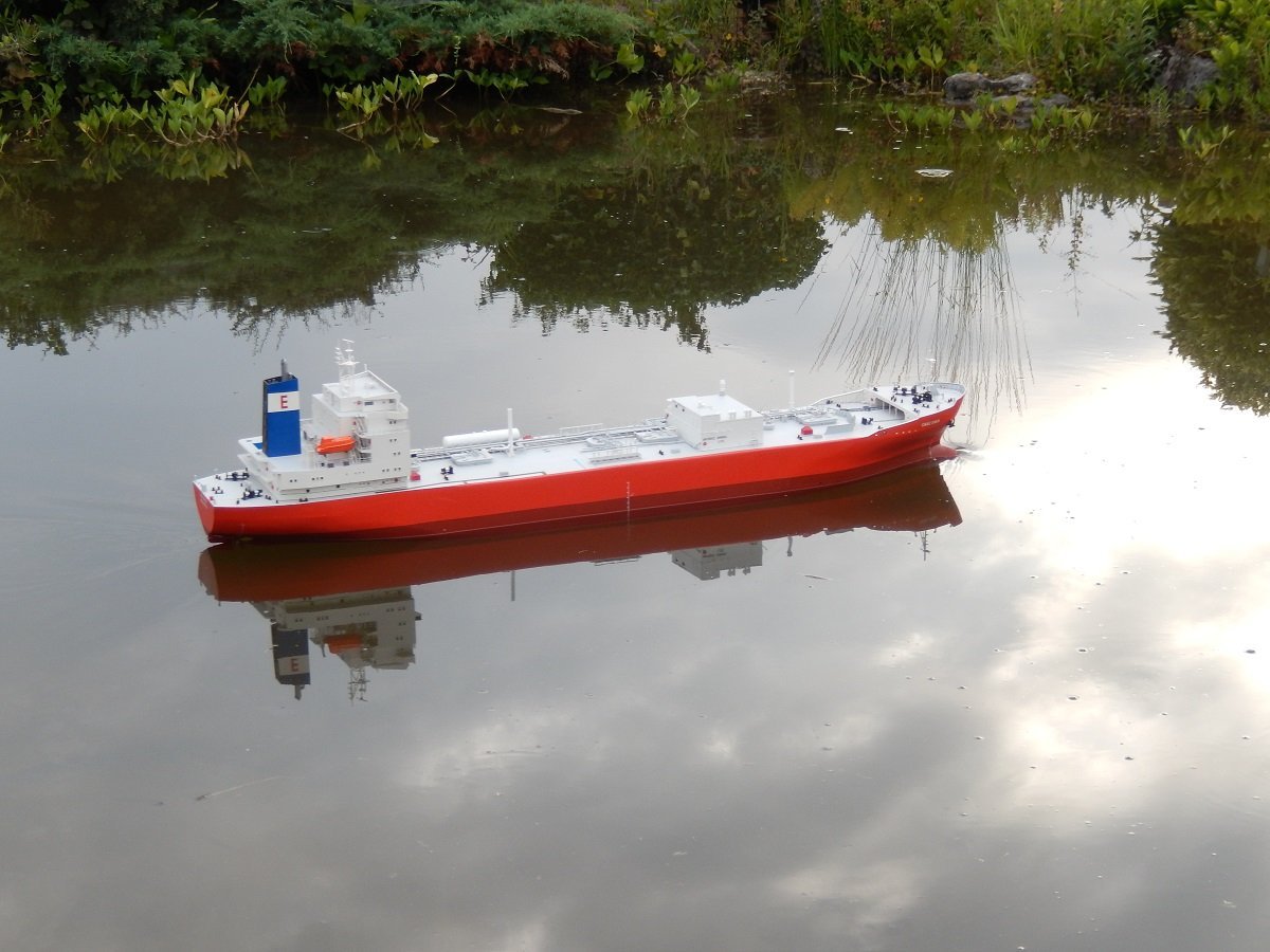
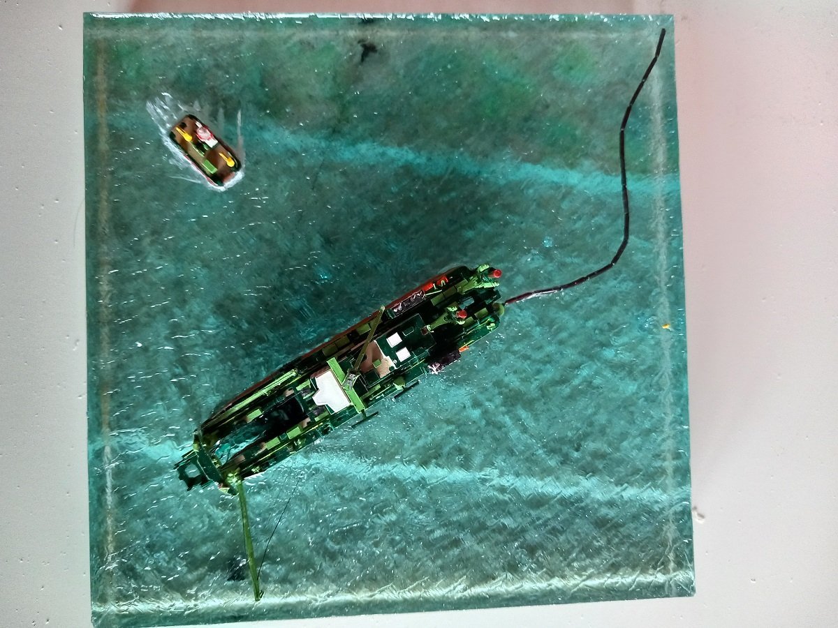
Well Mark those were exactly the ones I had in mind. I'm sure Glen can build them in 1/500, but I'm just starting to think he doesn't like penguins... Pretty sure if you asked him to model longhorns in that scale, he'd do it! Wait a second, didn't he have longhorns in one of his projects??? I noticed it's been a while since the last update. I'm actually at a stage where I consider the build complete. I've installed the lifeboats and fast rescue boat as well some masts (left off some detailing as it would be overscale and clutter the build), and eventually the yellow buoy that marks the anchor position of the floating line, and which holds the line that they use to retrieve and move such anchors. Here is a close-up of the lifeboat. I first made the davits, with their boarding platform attached, then attached the lifeboat to the platform and eventually used the davits to anchor the thing onto the vessel. For the rescue boat I used a more conventional approach and I first built the cradle with davit, and then mounted the boat inside of it. Here is a top view of the result. You can make out the small yellow buoy on the edge of the diorama near the floating line. The acrylic gel still allows you to see the side wires from the top, but the thinner anchor handling wires have become nearly invisible due to the distortion. This whole diorama measures 14cm x 14cm (around 5.5 inch x 5.5 inch). I just need to make a case for it, as I really don't want to dust this off too many times... Time for the Chaconia tanker to take center stage again in my workshop. Although I have some bottle-projects in mind, I don't think I'll do any side projects as I'm likely to get caught up in those by curiosity with the likely result of me abandoning the big ship again...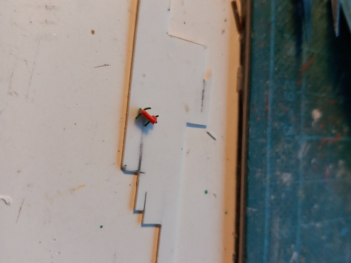
-
Hi Phil, Although it's one way to approach it, I do believe it poses a few "problems" as well. Occasionally I evaluate smaller objects on credibility as well. For example the ballast hatches, I could leave off the bolts and handles as I'm really not going to model everything the size of a bolt on that vessel. However, that leaves the hatch as just a rounded off plate, which looks rather toy-ish when looking up-close. That's why I modelled at least something resembling a bolt. I was at some point in the past looking at some very nice modern RC frigates, I believe also in 1/96 - 1/100 scale, however they looked a bit bland. So I started wondering what the issue was with these very nice models. After a closer inspection I noticed the watertight doors didn't have cleats/handles and gratings weren't truly represented as gratings. Small details that would have made a world of difference. I believe also the rivets on Nils's Ergenstrasse are a good example, they may be a bit over scale, but without them, I believe his model would not breathe the steam-age atmosphere it is breathing out right now. It gives that little extra that makes a model shine. Does that mean he really needs to model everything the size of those rivets? I don't think so, as it would at some point, even when just slightly over scale, clutter the vessel and make it less credible again. All in all I believe the real problem with this is that you have to evaluate for every little object whether it's worth the effort to make it and whether it would improve or deteriorate the quality of the model, keeping in mind a certain balance throughout the vessel (cannot put fire boxes on one part of the vessel to give it some credible detail, while leaving them off on other parts of that same vessel...) You will also see in some pictures of the lifeboats in the future, that I did put the grab lines on the side, while in fact, and most people won't notice without intricate knowledge of the matter, I left off the spray system. Lifeboats on tankers have a spray pump that pumps sea water over the top of the boat to protect it from burning oil/gas on the water surface during an abandon ship situation. This piping is larger in size than the grab lines, but would have been very difficult to build and, in my opinion, add very little to the overall impression of the vessel. That's why I left that off. The grab lines on the other side, are something seen on even old lifeboats and add the impression of a super detailed and complete lifeboat model. For the name on your winch, I believe the same is true. It wouldn't really add to the quality of the winch if all, or at least some detailed handles and plates are modelled on it. Nobody would be looking for a manufacturer name on something like that (but if it didn't have brake or clutch handles, I'd definitely notice 😜)
-
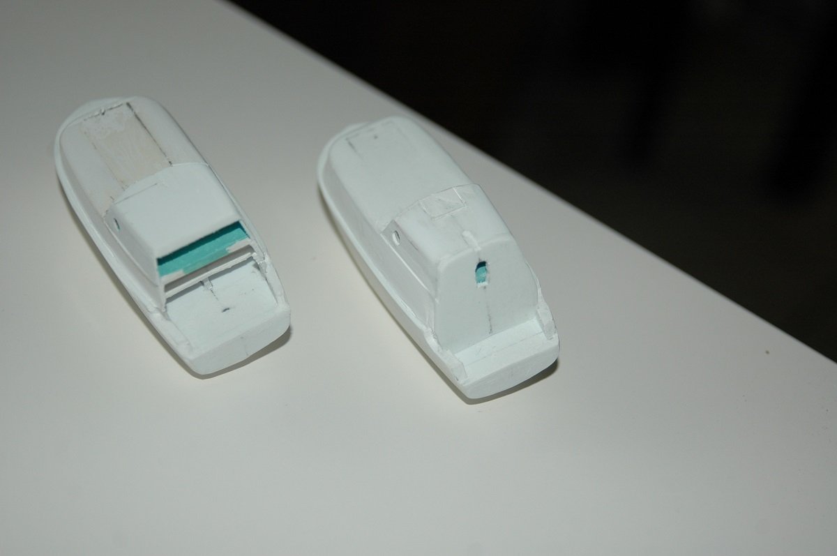
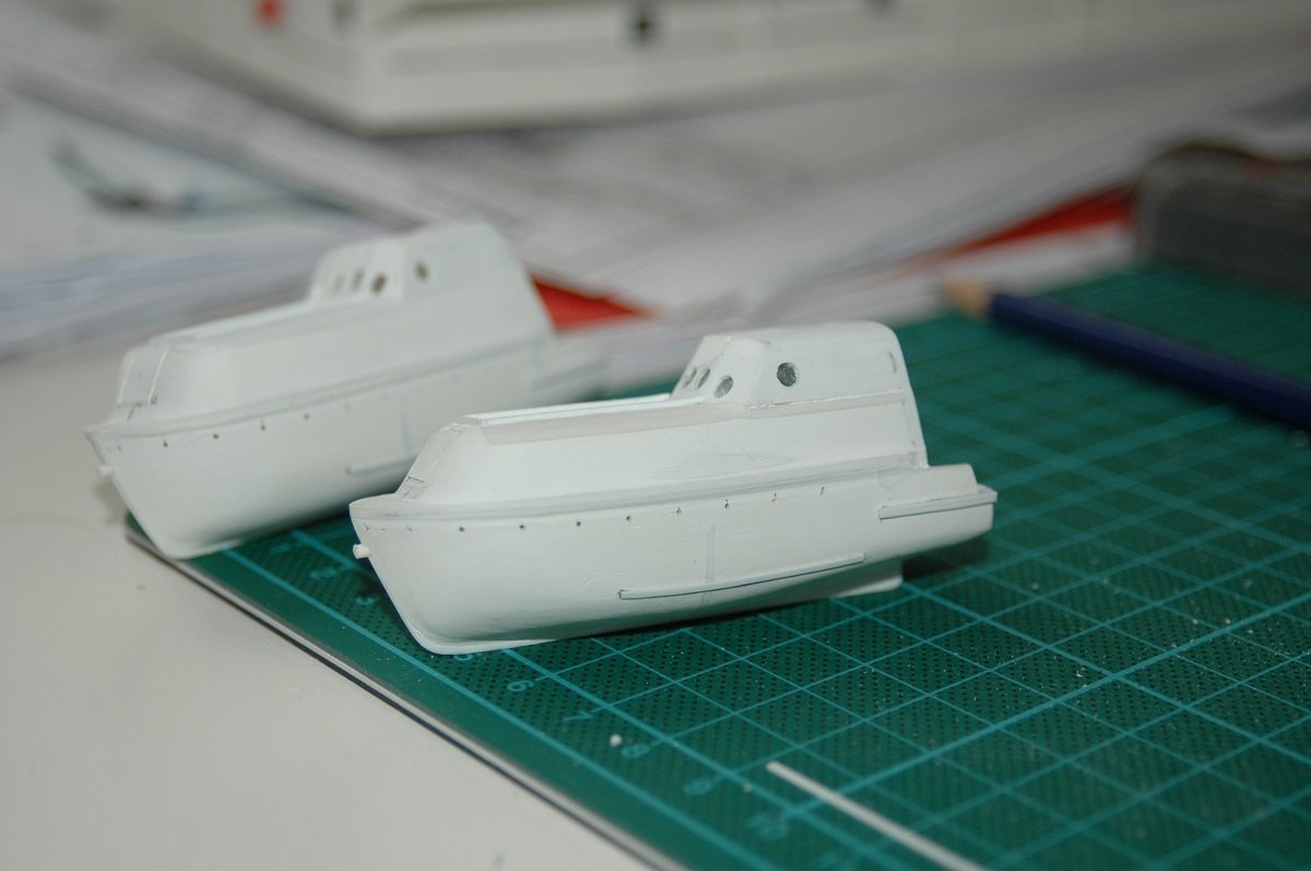
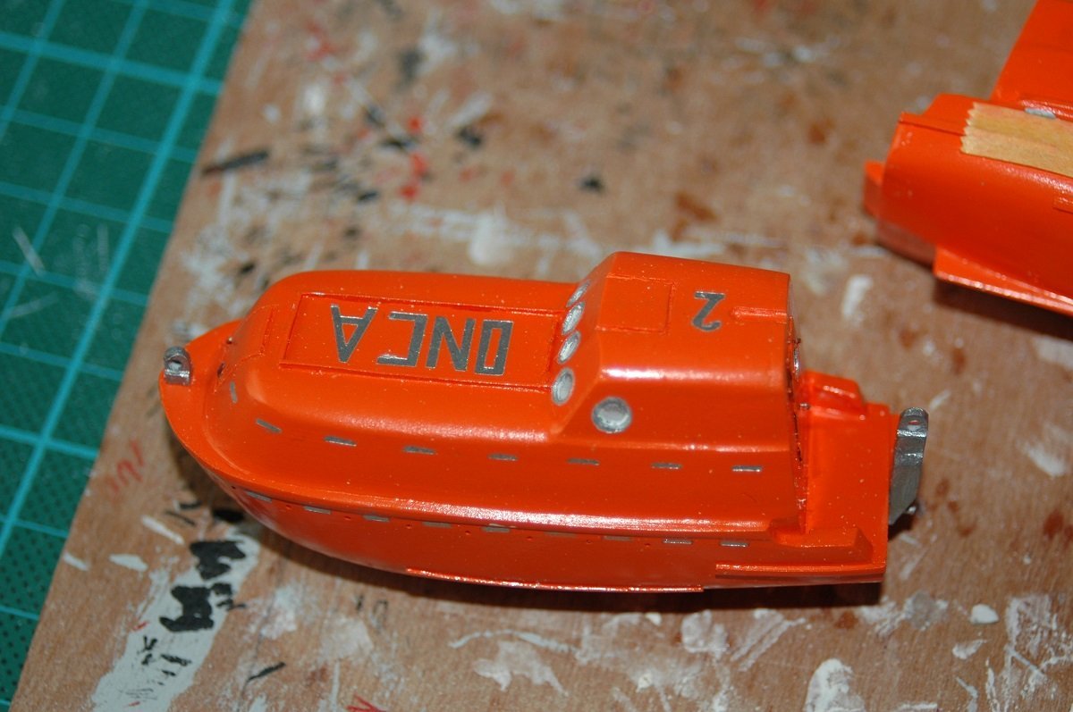
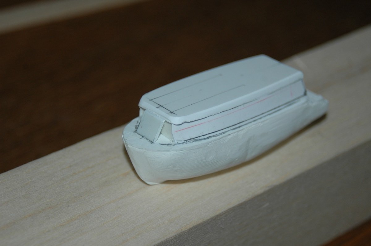
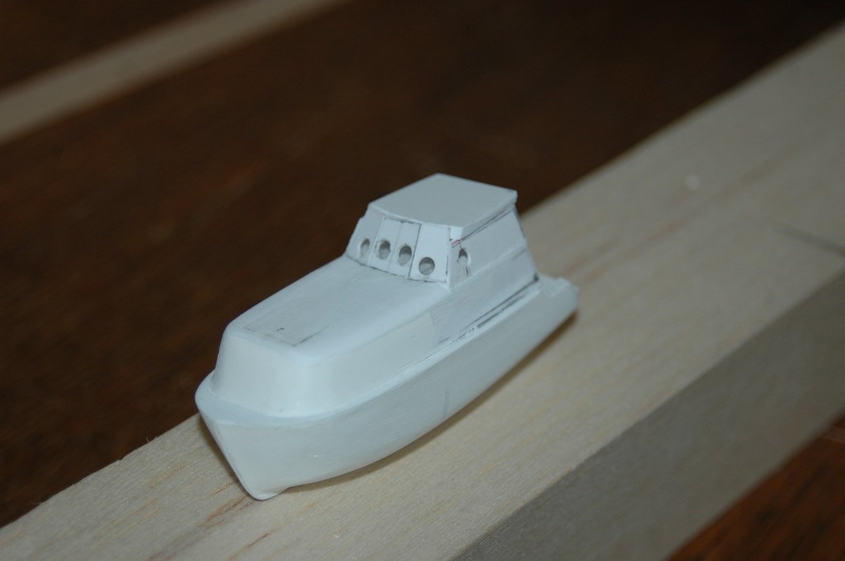
Thanks for the comments and likes. I guess I chose to detail it this far was because I wasn't planning on sailing too much with it... Furthermore I was used to build in small scale, detailing as far as I could and got a huge load of reference pictures of the whole vessel. Eventually having too much reference material is also a curse as you can basically make out every bolt on a ship, and in my case, feel obliged to replicate it. The large size of the vessel also allowed for this amount of detailing, with a her freeboard there is not much water coming on deck, I'm also only using it in calm weather. Here are both lifeboats in later stages compared to their smaller 1/700 brother onboard LPGc Donau (one of my earliest scratch builds). I needed to replicate that typical inside colour, although nowadays it's more yellowish white in the newer lifeboats. And with some strips and bits added. A big rectangle with raised edges was added on top, on these boats this was the obligatory means to collect rain water. Nowadays they put some small bucket, again a lowering of standards... Although the top surface of the boat is unlikely to be really clean, at least you'll catch some rain water. Although the bucket will be clean, I doubt you'll catch any decent volume of fresh water with it. The small holes in the side are made to attach the grab ropes later on. And with a coat of paint. I tried to replicate the "reflective SOLAS tape" by small silver rectangles. Additionally the boats are marked with the mother vessel's call sign (always beginning with ON for Belgian merchant ships, OR for Belgian working vessels) and the number of the boat were also marked on the top. Hooks were also added, The aft hook has a small brass rod at the bottom, in reality this is used to keep the seafastening lashings in place, but in my case it also adds to the strength to hold the hook, and boat, in place in the davit. Wouldn't want the hook to break off the boat during sailing. And the start of the davits. This is a dry fit. I built them according to the drawings, but always check to see if it actually fits. This way I want to make sure it doesn't look "off" in the end, by having short arms etc. Lots of test fitting before finally gluing. I jumped from piping to the lifeboats to get to something with an end. The lifeboats were a project on their own, one where I could see the goal, which is difficult in the large piping job. Just to keep me motivated before switching back to piping. That said, we are nearing the actual situation. A few more updates and we will have arrived at the point where I got stuck/uninterested.
-
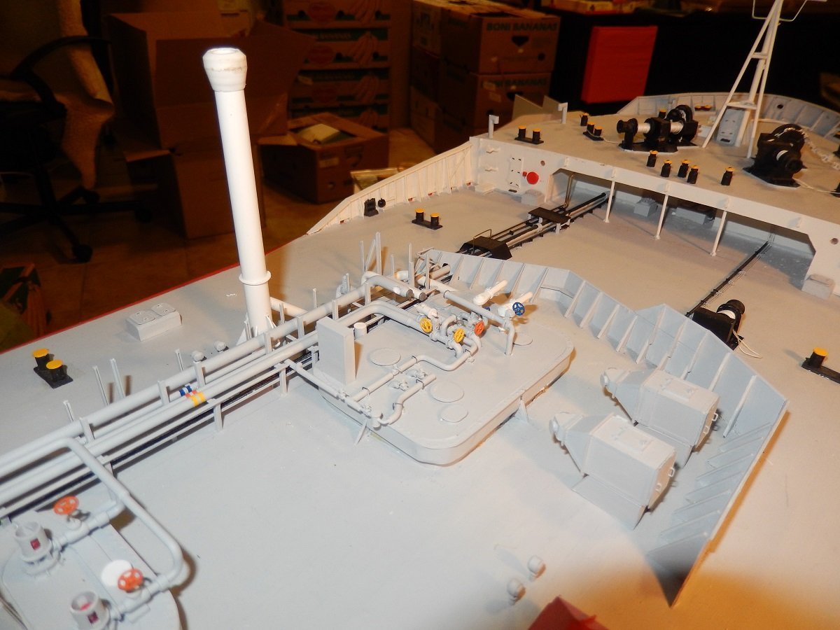
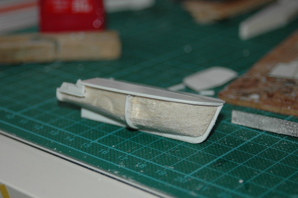
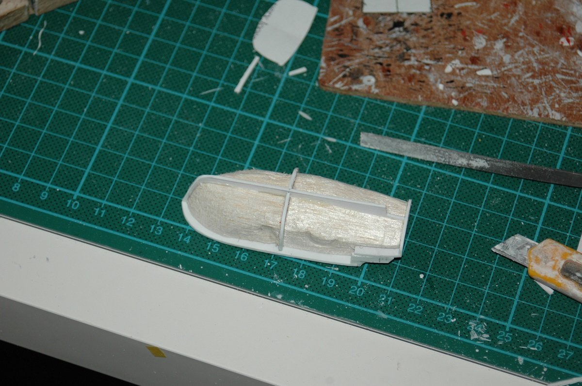
And we continue with more piping. It also seems I've taken her out to the water more than I can remember. Mainly concentrated on the Inert Gas line - vent mast etc. For the vent mast top I used a small Proxxon Lathe, but my main issue was that I didn't have rods of proper diameter to turn it from. Turning styrene is also tricky since occasionally the chisel grabs the styrene and the whole things get pulled out of the chuck. For the forward vent mast I glued styrene tubes of consecutive diameters into each other, but I guess I was very lucky to get that vent mast head done as I've done around 4 attempts for the second one and never succeeded in that... Nowadays however things are easier to get, so guess I will get a proper rod to turn the head of the aft vent mast. And the start of the lifeboats. To save myself some time, I used a balsa construction on styrene plating. I used the top and side view of the boats, filled the open spaces to create some hull volume and then added milliput epoxy filler over that to smoothen out the hull.
-
Hi Nils, I've been collecting various telephone and electronics wires. Some of them have tiny copper wires, but with a stainless steel look, inside. They go to less than 0.1mm diameter and can be turned into a single wire with a 0.2 -0.3mm diameter. I used a drill with something of a sliding weight on the other end to turn them. They are not springy as the ones Phil mentioned. On the other side, I think the rope you used has a certain "wire" look to them and look very realistic. I doubt many people would notice the difference. We only notice because of the close-up pictures, so I'd leave it as it is. Wires are generally also greased and/or dirty on ships, so they don't really look like steel in many cases. From a distance they appear black rather than shiny.

