HOLIDAY DONATION DRIVE - SUPPORT MSW - DO YOUR PART TO KEEP THIS GREAT FORUM GOING! (83 donations so far out of 49,000 members - C'mon guys!)
×


yvesvidal
-
Posts
3,607 -
Joined
-
Last visited
Content Type
Profiles
Forums
Gallery
Events
Everything posted by yvesvidal
-
 Very impressive model. Museum quality. Yves
 -
What you do to his hull is a good thing and an insurance to its integrity if you ever float it on a pond or lake. When I was a kid (6 or 7 years old), I built a PT-109 from a wood kit (Can't remember the brand). The hull was made of planks like yours and I glued it with white glue for wood (there was not much choice at that time). The vessel was powered with a small electric motor and after painting it with a medium grey, I took it to the nearest lake. The boat did well for a few minutes, circling all by itself (no RC) and suddenly started to behave like a diving submarine. The motor quickly stopped when submerged and my father and I tried to recuperate the PT-109. When we could grab it, the planks on the bow, had opened like the petals of a flower, allowing plenty of water to rush in. White glue for wood was not really designed for water usage, even when dry. After that, I was always using two components slow curing epoxy glues and the problem never happened again. Yves
-
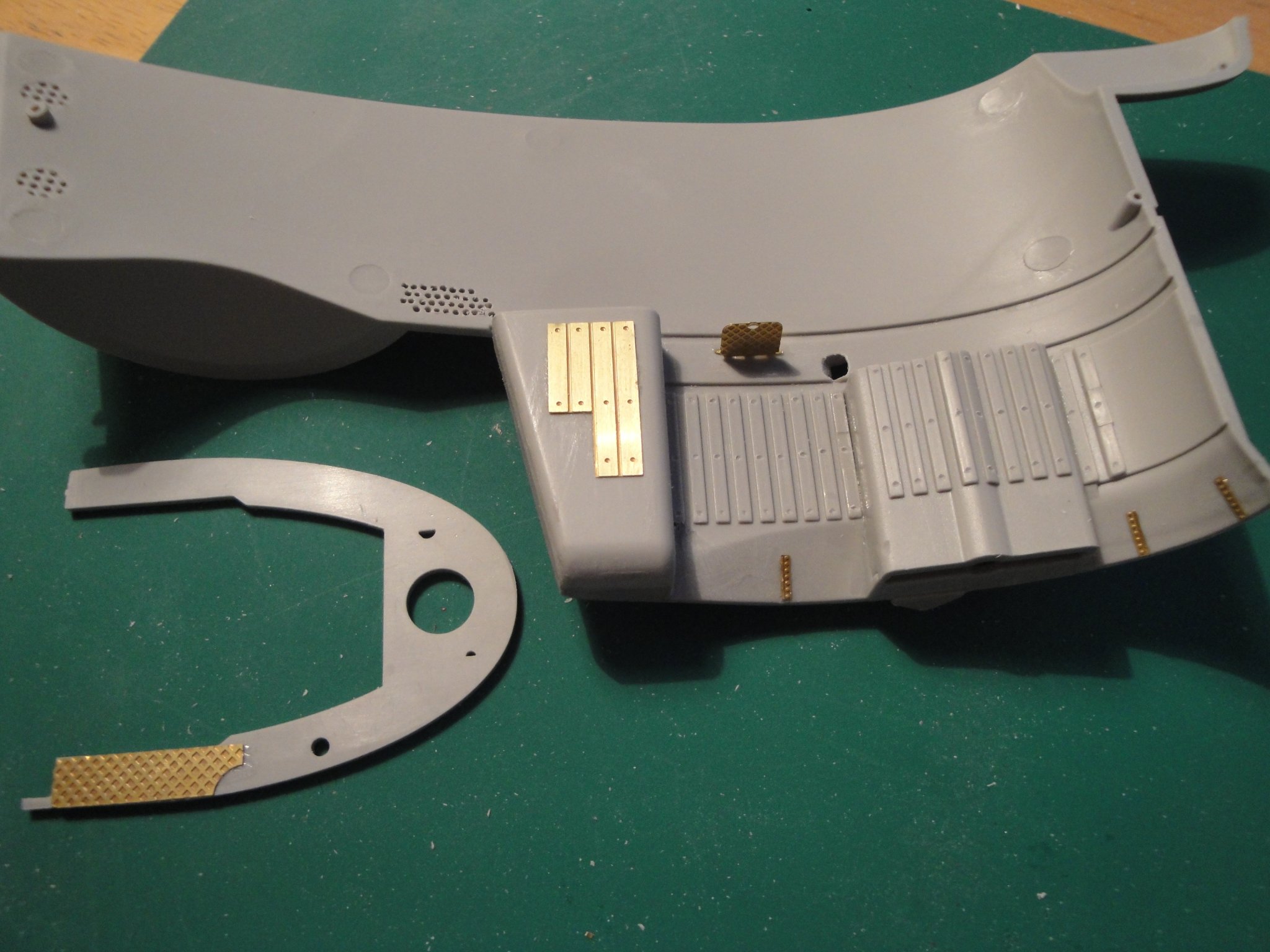
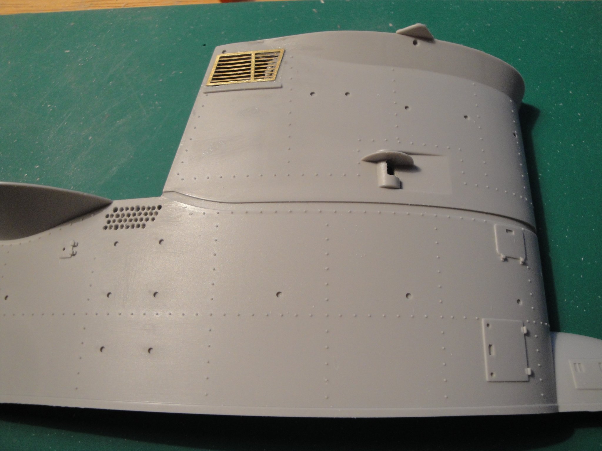
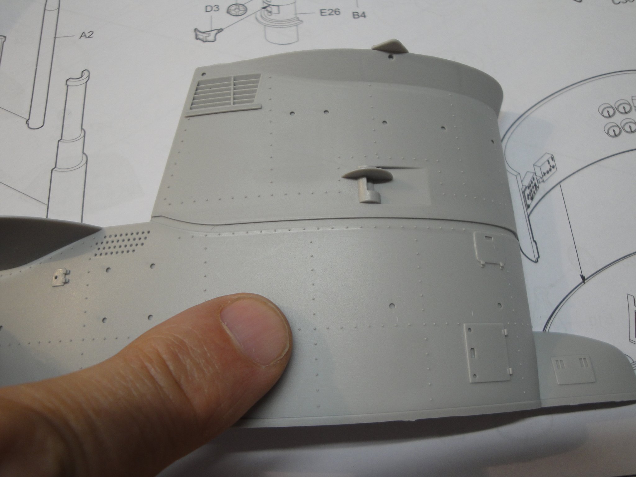
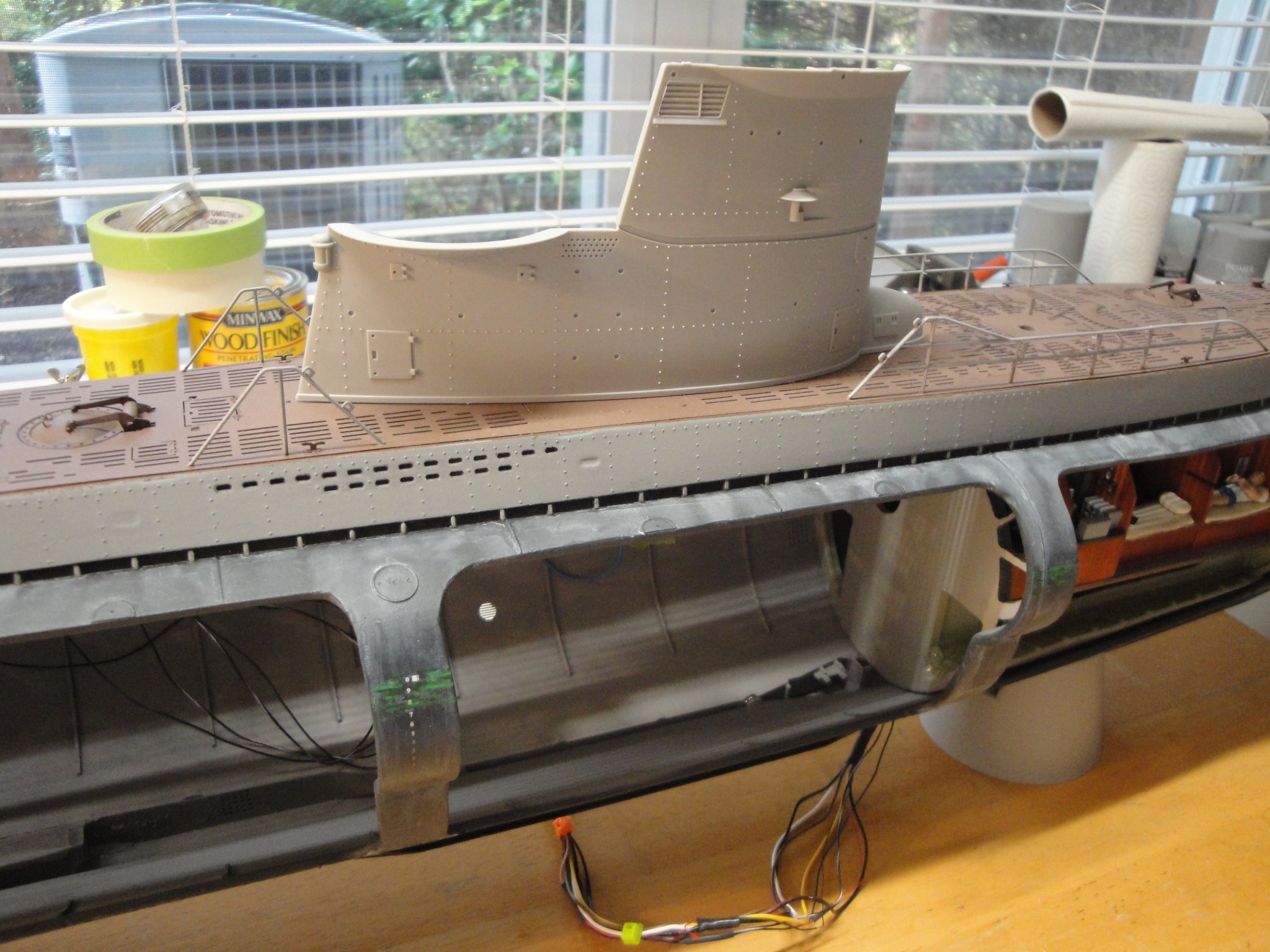
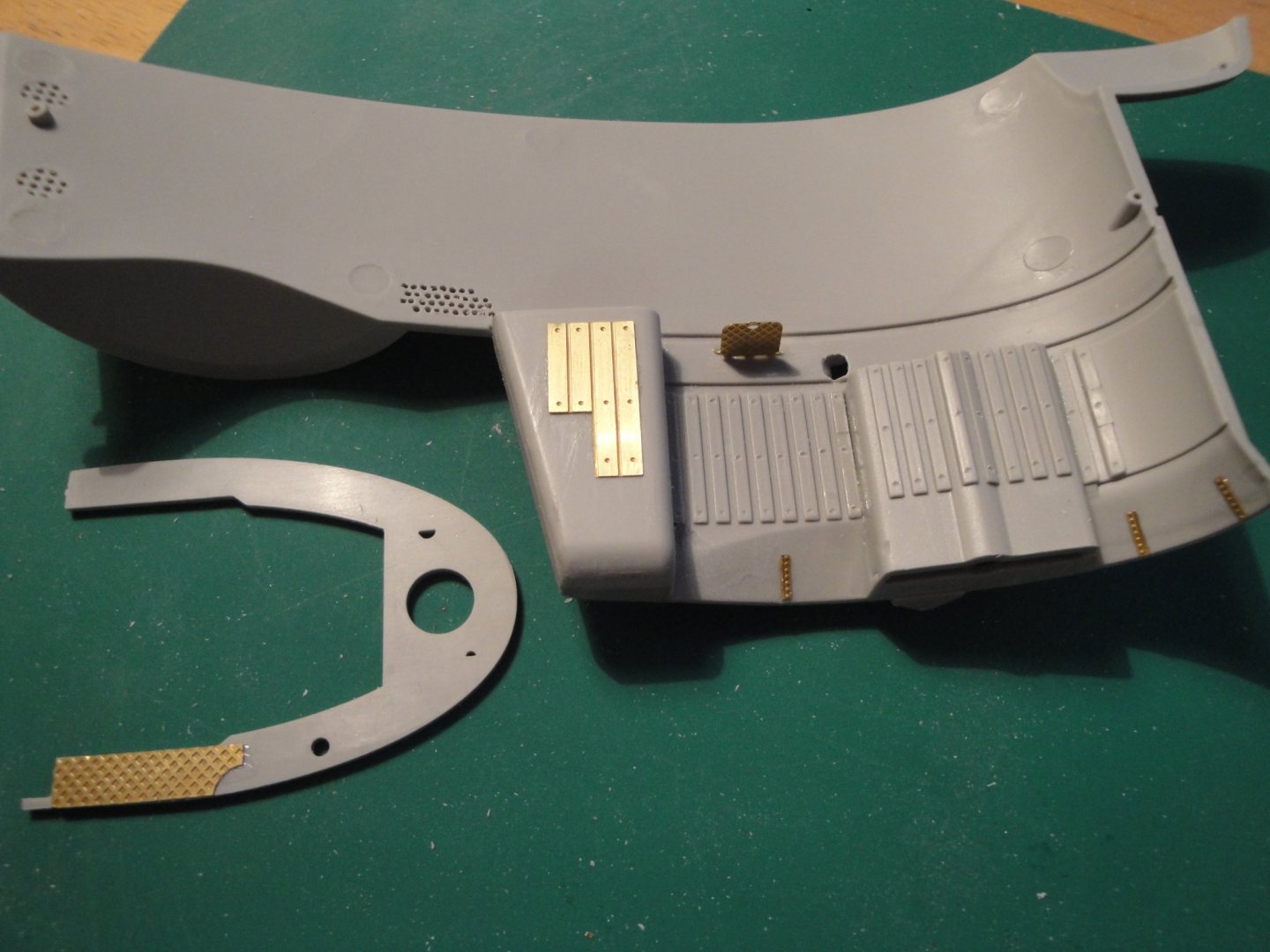
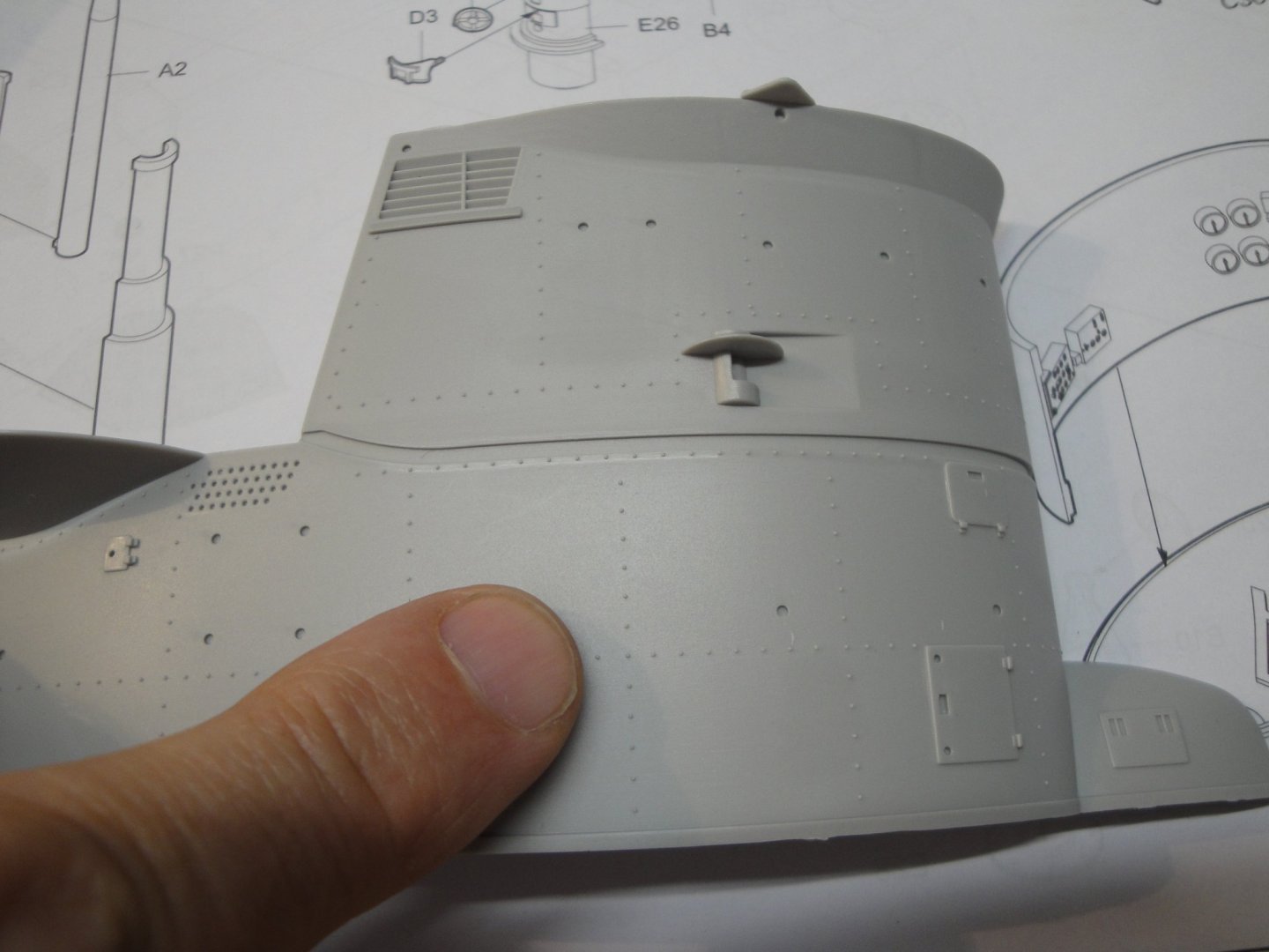
Few progress to report. Not much going on but very time consuming. I drilled the opening for the fresh air admission for the starboard diesel and glued the PE grill. The position light was also opened. I am still debating how I will make it working as even 3 mm LED will not fit. I will probably use a micro SMS LED with a colored piece of translucent plastic for the lens. Trumpeter did not care to drill the large amount of holes on the side, either. I wished a PE part was available for that section of the sail, but RCSubz did not include it. On the other side, a few more details have been glued: wood slats to protect the crew from the cold and shocks as well as anti-skidding steps for the vigil. Again, Trumpeter did not care marking the wooden slats with the three lugs to hold them to the side of the sail. I did it with a small drill. It is worth spending some time on the conning tower as it is one of the highlights of a submarine. Most likely, this section will take many days and weeks before it is completed. Yves

- 760 replies
-
- 18
-

-
I like the clear/light oak better, but that is just a question of taste. The dark oak is more traditional. The light oak more modern. Look at what Dubz (Dirk) does with his beautiful stands. He uses something that looks like ashes (or lavis in French) and it is beautiful. Yves
- 550 replies
-
- 1
-
-
- confederacy
- model shipways
- (and 1 more)
-
Mahenke, If you re-read the part related to painting the hull, you will see that I have not used Tamiya but Humbrol/Revell paints. Tamiya was only used for the deck. And no, the main hull is not too big to be airbrushed. I did it with a dual action Paasche airbrush, using one of the largest nozzle I had. It takes some time but can be done actually quite well. Yves
-
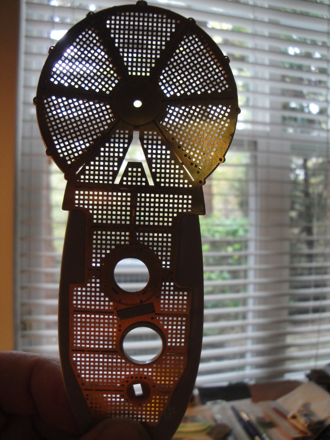
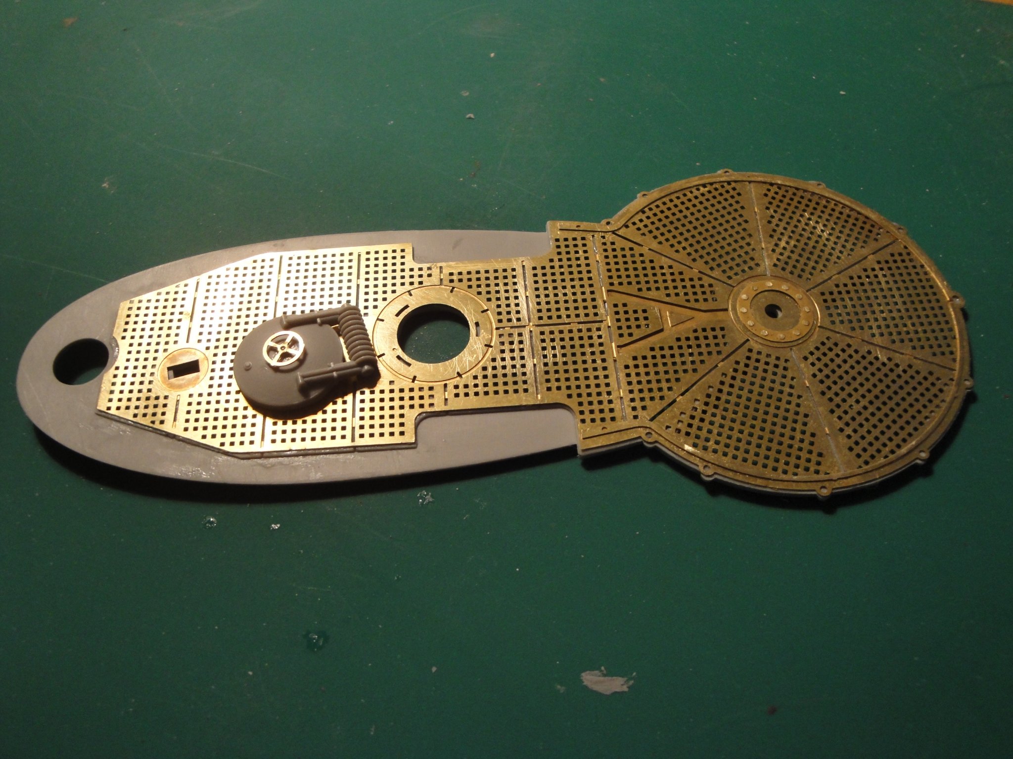
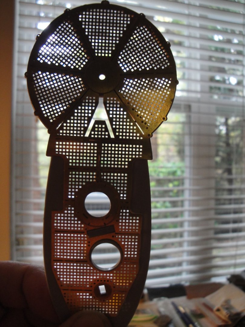
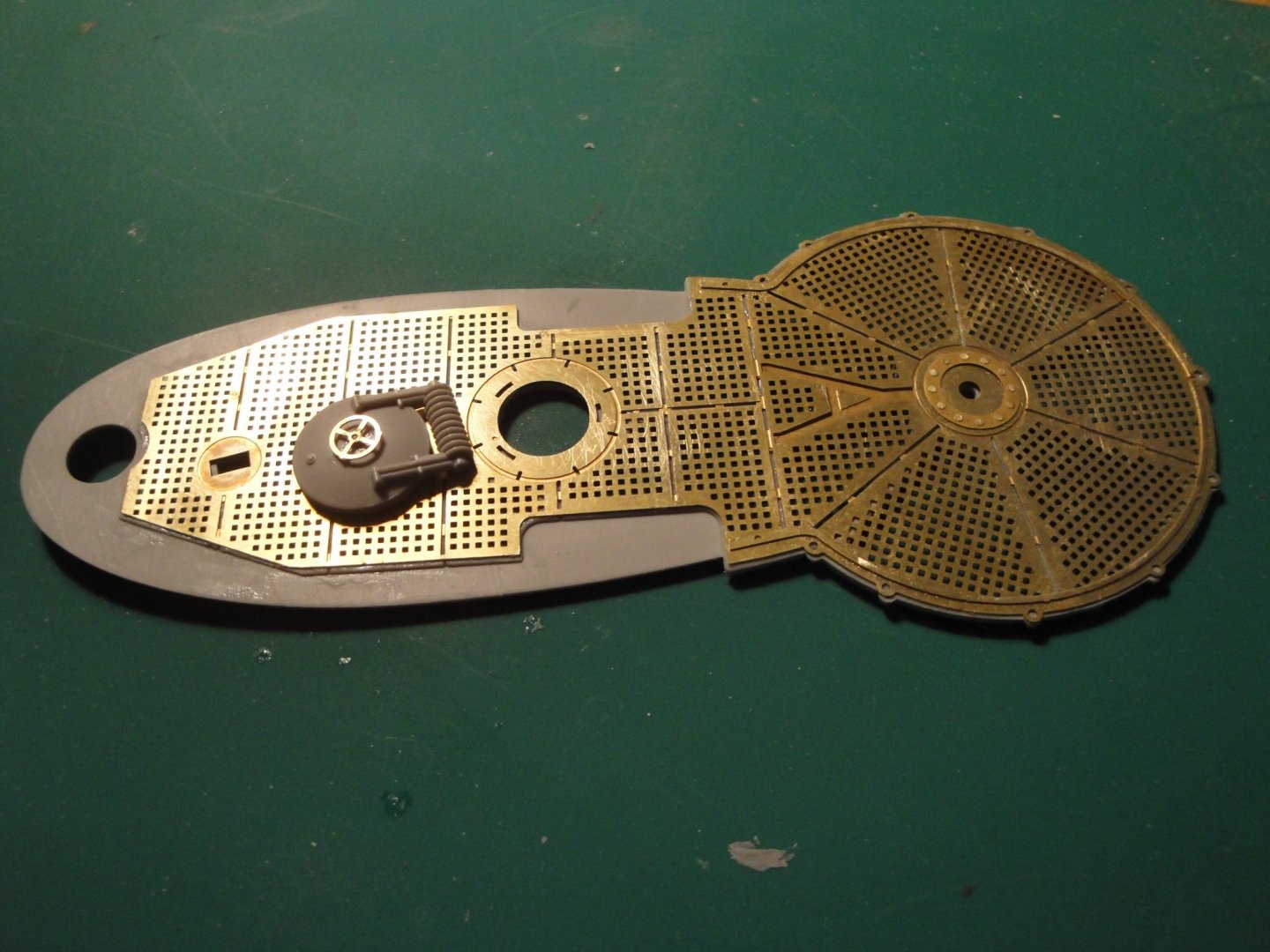
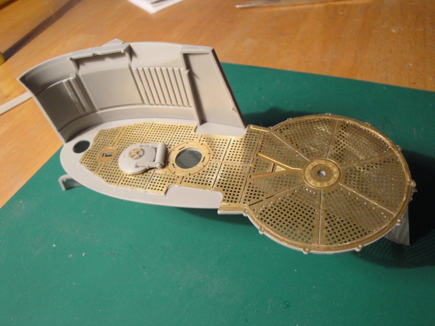
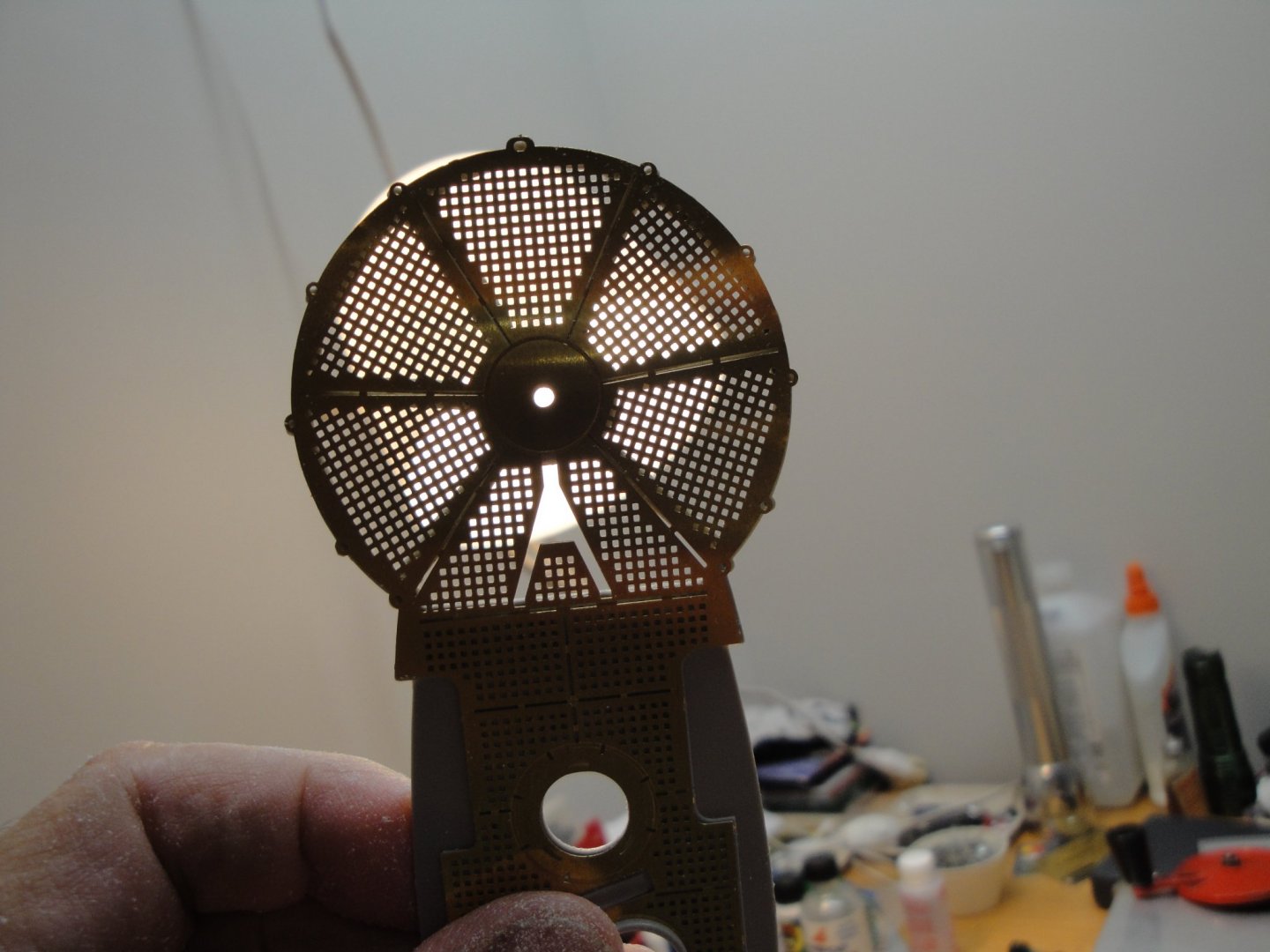
The creation of the Swiss cheese is almost over: There is not much plastic left on that part. But the light test reveals that all has been cut accordingly: Time to glue the PE on top of the plastic skeleton and to add the hatch lid: Again, the RC Subz photo etched part are a very nice and close match to the Trumpeter parts. They definitely enhance the appearance of this model. Yves
- 760 replies
-
- 16
-
-
I agree with Katuna regarding the colors of lights. The Blue lights used in the movie Das Boot, may have been used just for dramatic purposes in the movie. The Red lights allow you to keep your nocturnal vision intact and that is why they were used in the control room and conning tower, for the officers and crew in charge of watching outside, during night time. I am not planning to use any Blue LEDs in my model, even though a lot of modelers have been doing it, due to the movie depictions. Yves
-
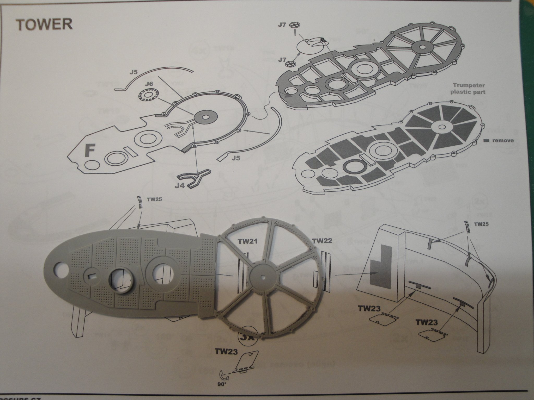
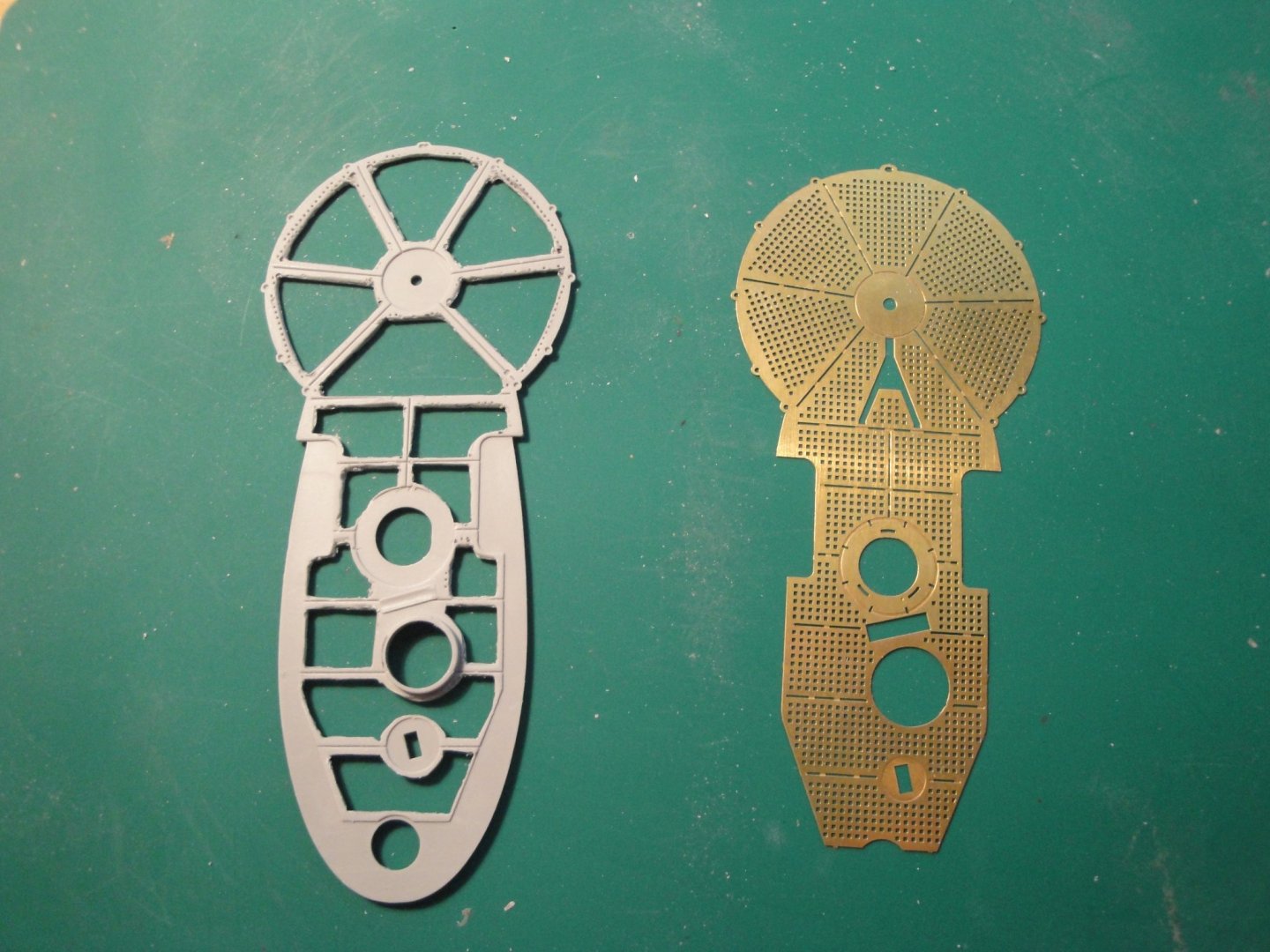
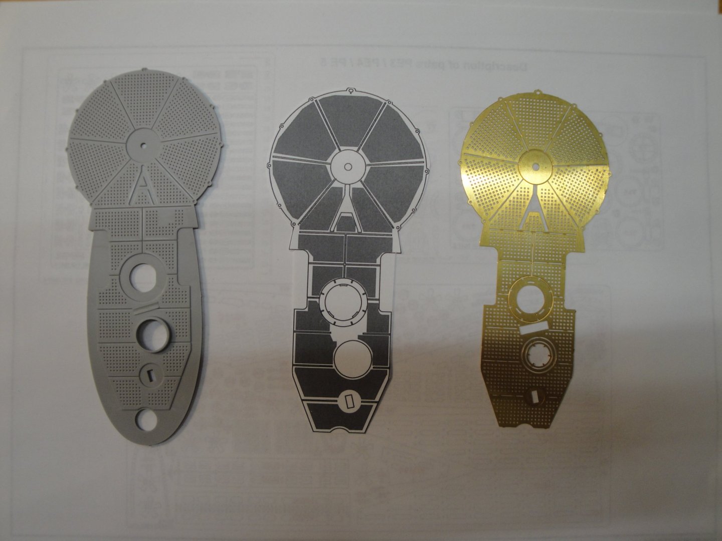
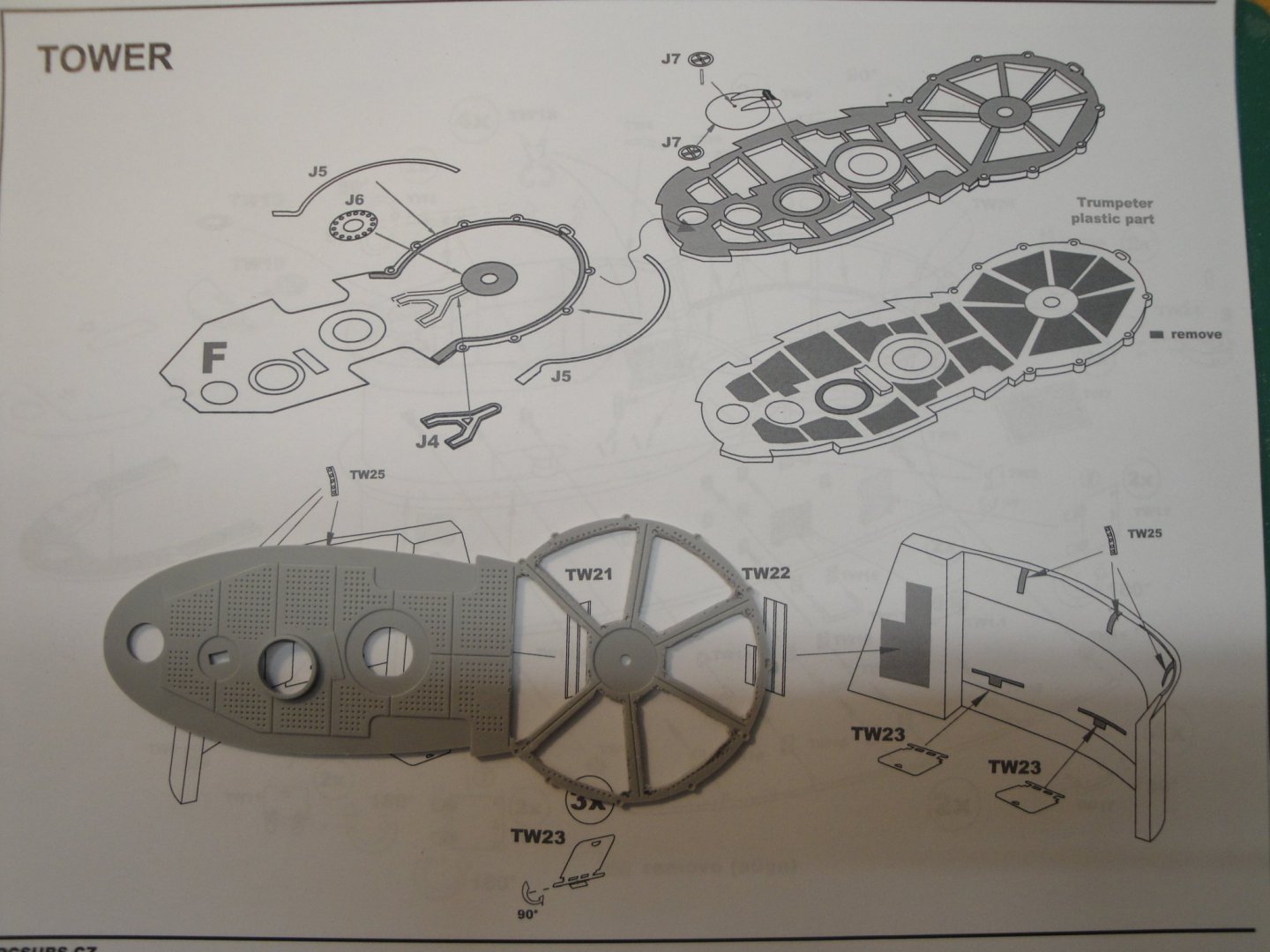
A few progress, as I am turning the sail floor into Swiss cheese. Again, the fantastic PE set from RCSubs is perfectly designed and provides a very nice fit: Nice instructions from RCSubs too, a lot easier to follow than the Trumpeter manual, which is rather vague: When I am done, that part will just be a skeleton. Yves
- 760 replies
-
- 18
-
-
7Youngs, Thank you for the generous offer regarding the circuit design. Due to the expensive proposition of manufacturing such a small circuit (a couple of prototypes would cost $350-400), I have decided to go with pre-made circuit boards. It is simple enough and works perfectly. As a matter of fact, I am also an Electronic and electrical engineer and have in the past realized multiple complex printed circuit boards as one of my hobbies, is to realize High-End audio equipment. Instead of AutoCad, I have used Eagle and a couple of other programs. My favorite remains Layo 1. I would love to see your model and you should start a Blog. I feel lonely at times with my German submarine, although the followers are very enthusiastic and supportive. Yves
-
It is just incredible what you can do with modern tooling. A CNC machine on three axles is a little marvel in itself. It is even better than a 3D printer, as it lets you pick up the material you want (wood, metal, resin....etc). Yves
-
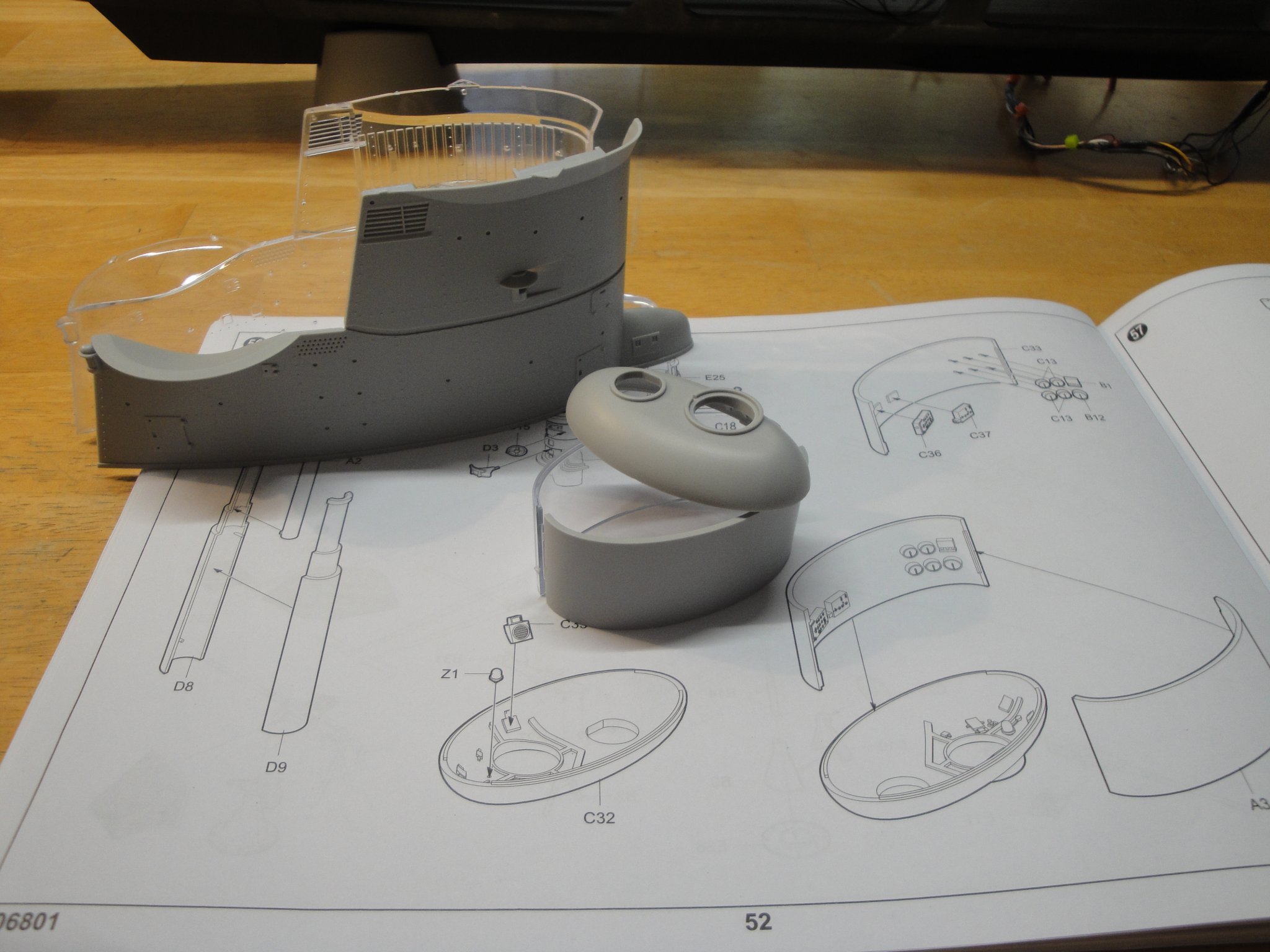
Decisions...decisions!! I am about to start working on the sail or what is also called the "Conning Tower". The name "conning" comes not from the conical shape but from the English term of "to conn a vessel from a vantage point or from a high structure". On a U-Boot, that was not so high and conning made you very wet, when the sea was rough. So, the Chinese Trumpeter screwed up royally. It is probably the biggest "quack" in the kit. The starboard of the hull is see through, but for the sail, they decided it was the Port side. Duh.... Was this intentional, was it a mistake? We will never know, but the consensus among modelers, is that they got it wrong. Another problem is that the inside of the sail port side is not available or represented, since it was supposed to be transparent. To show it properly, we would have to rebuild entirely, the little tub parts. Besides, I have no idea what the Port side looks like from the inside. Finally, the opening is really small and no larger than a small postal stamps. There would not be much to see. Finally, I kind of like the sail being "solid" as it blends more harmoniously with the bridge and provides a more realistic depiction of the upper part of the U-Boot, than any contraption I could design and which would probably end up far from the reality. With that being said, I think we are going to build that sail "solid" and focus on the visible and outside details with plenty of plastic and Photo-etched parts. We will also add some lights to increase the complexity of the electrical circuit. The sail will not be glued on the bridge, until I figure out how the various periscopes, air intakes, antennas and access hatches work out with the control room, underneath. Yves


- 760 replies
-
- 18
-
-
Kevin, thank you for the compliments. However, rest assured, this is far from being completed and you will read me for a few more months.... ☺️ Yves
-
What a beautiful trawler. Very British in appearance and timeless in its lines. Yves
- 337 replies
-
- 5
-
-
- finished
- mountfleet models
- (and 1 more)
-
Thank you all for following and appreciating what I am doing. It is a lot of work and it is starting to pay off, finally. At this stage, I have to assemble the sail/conning tower and the three remaining compartments. Plus a multitude of details, with the deck, guns, rigging.... Yves
-
Yes, I have been thinking about this. Right now, it is all fresh in my mind, but in a few months.... it won't. I will be drawing one, for sure. Yves
-
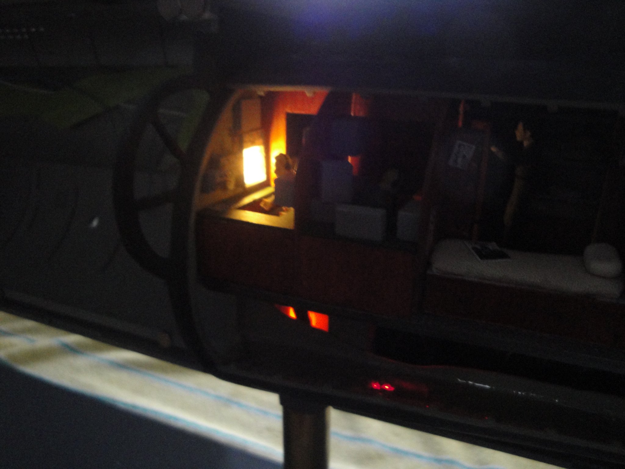
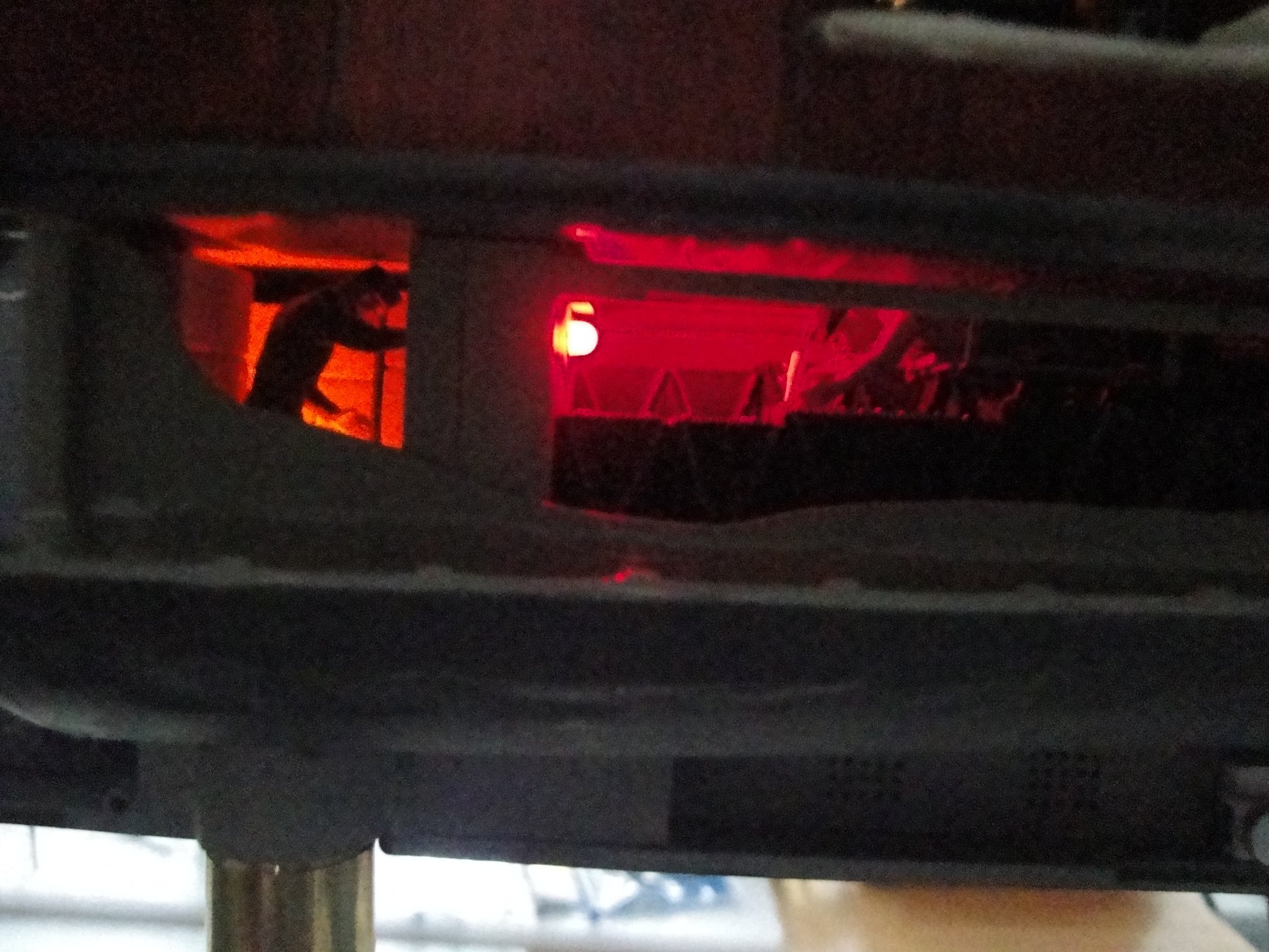
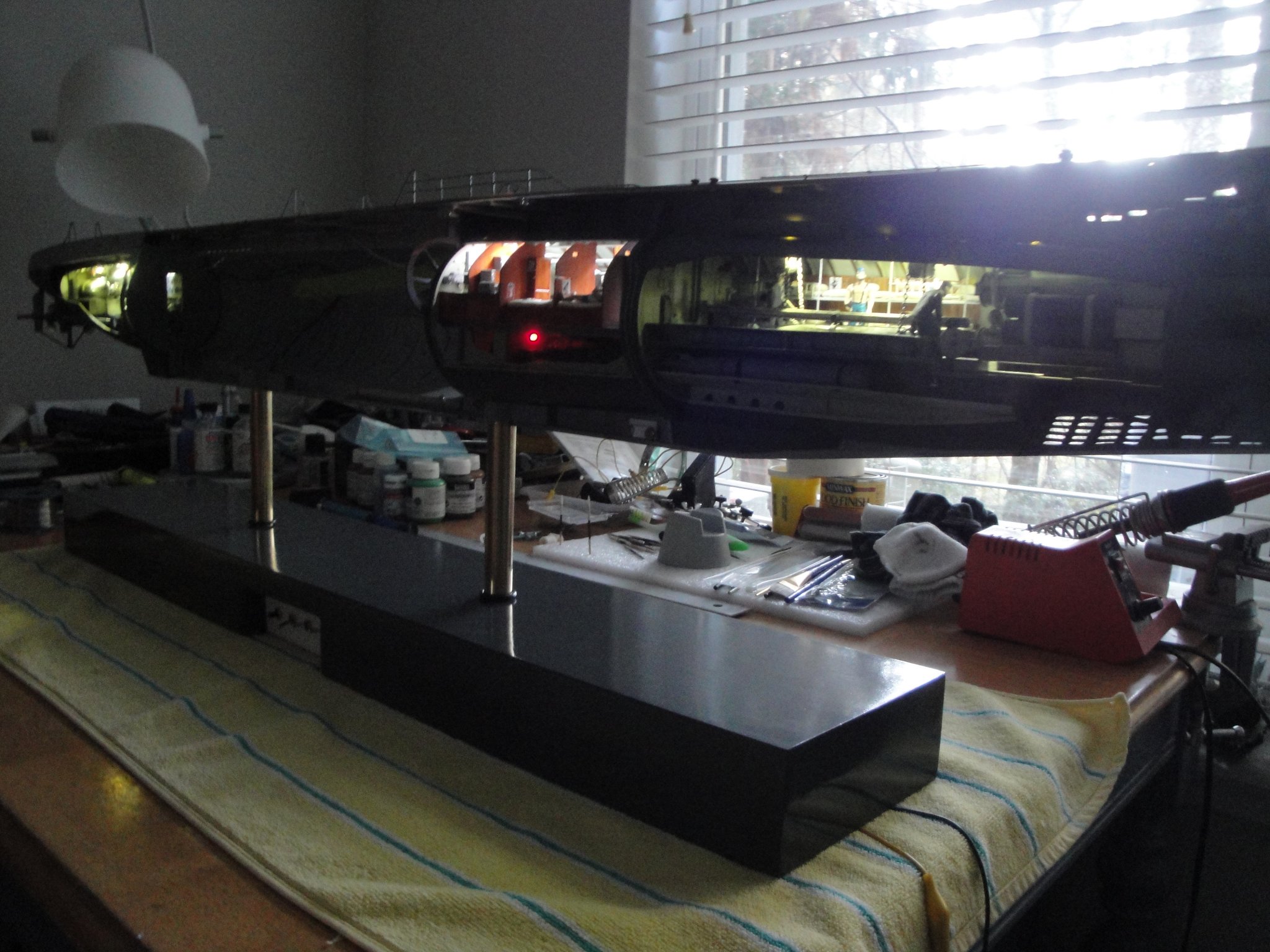
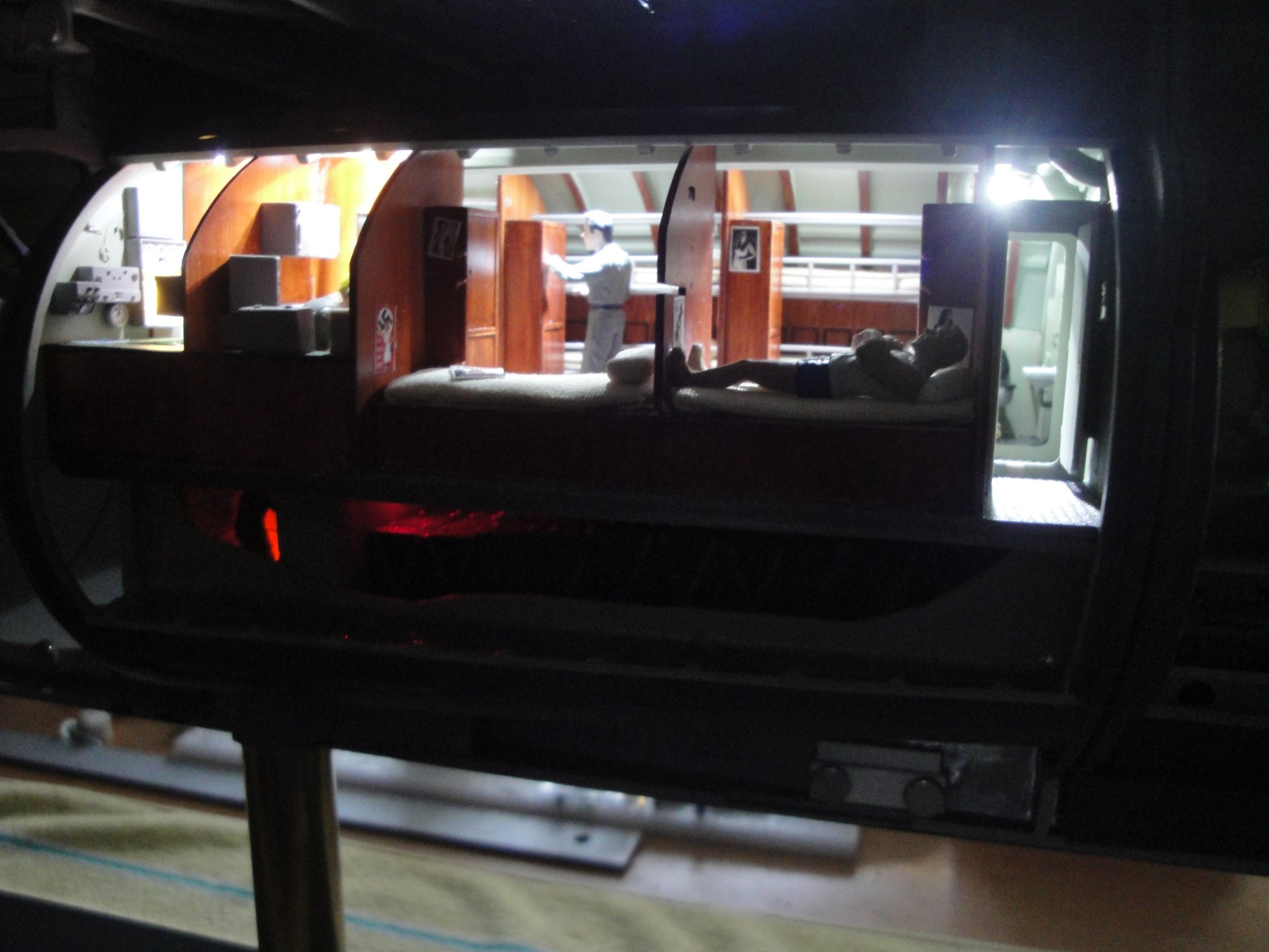
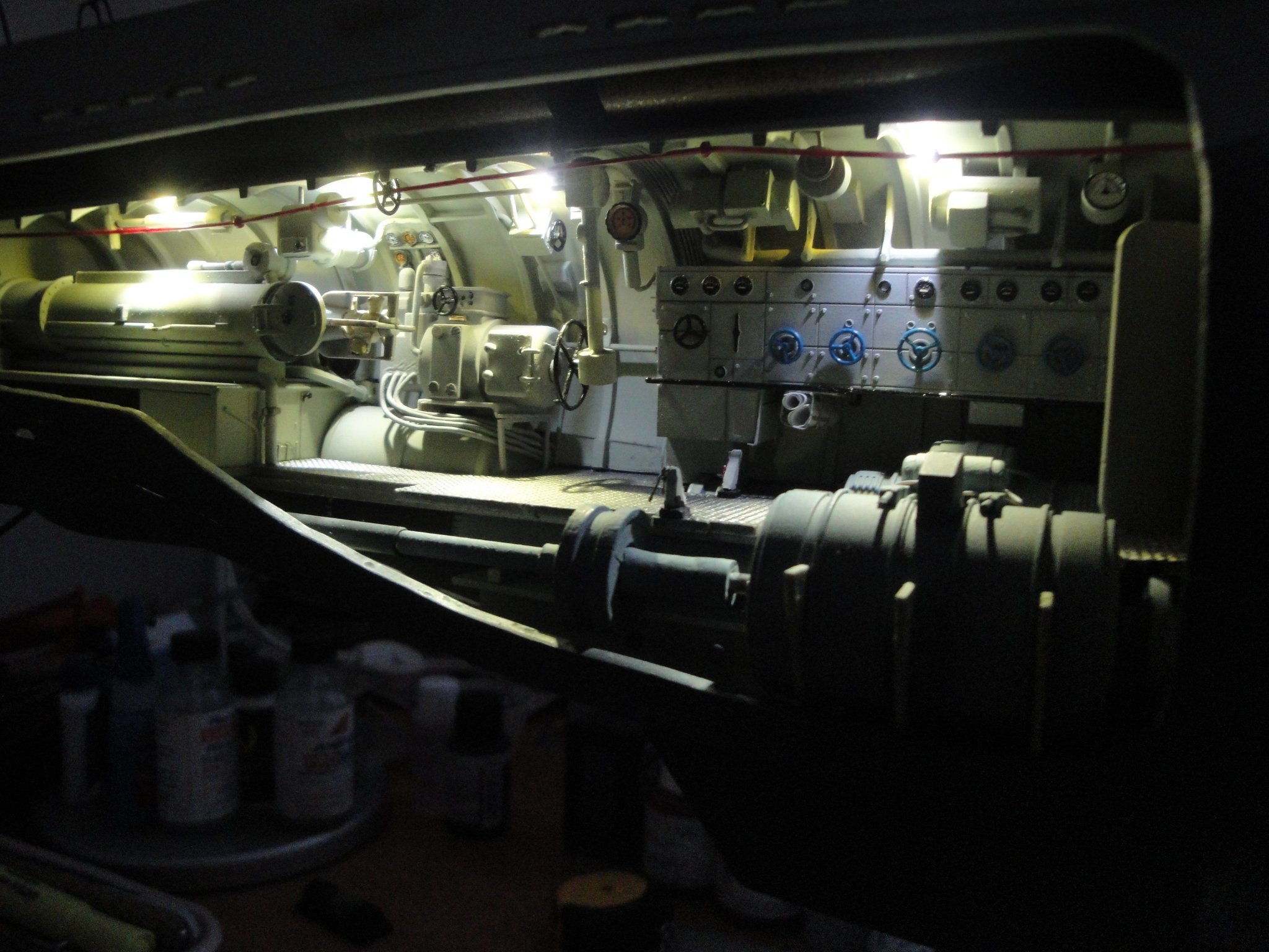
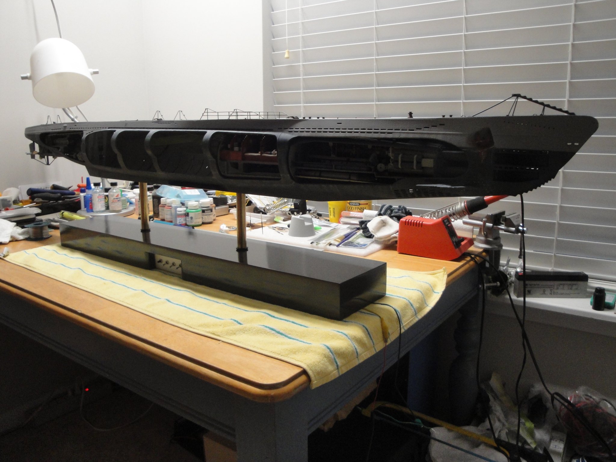
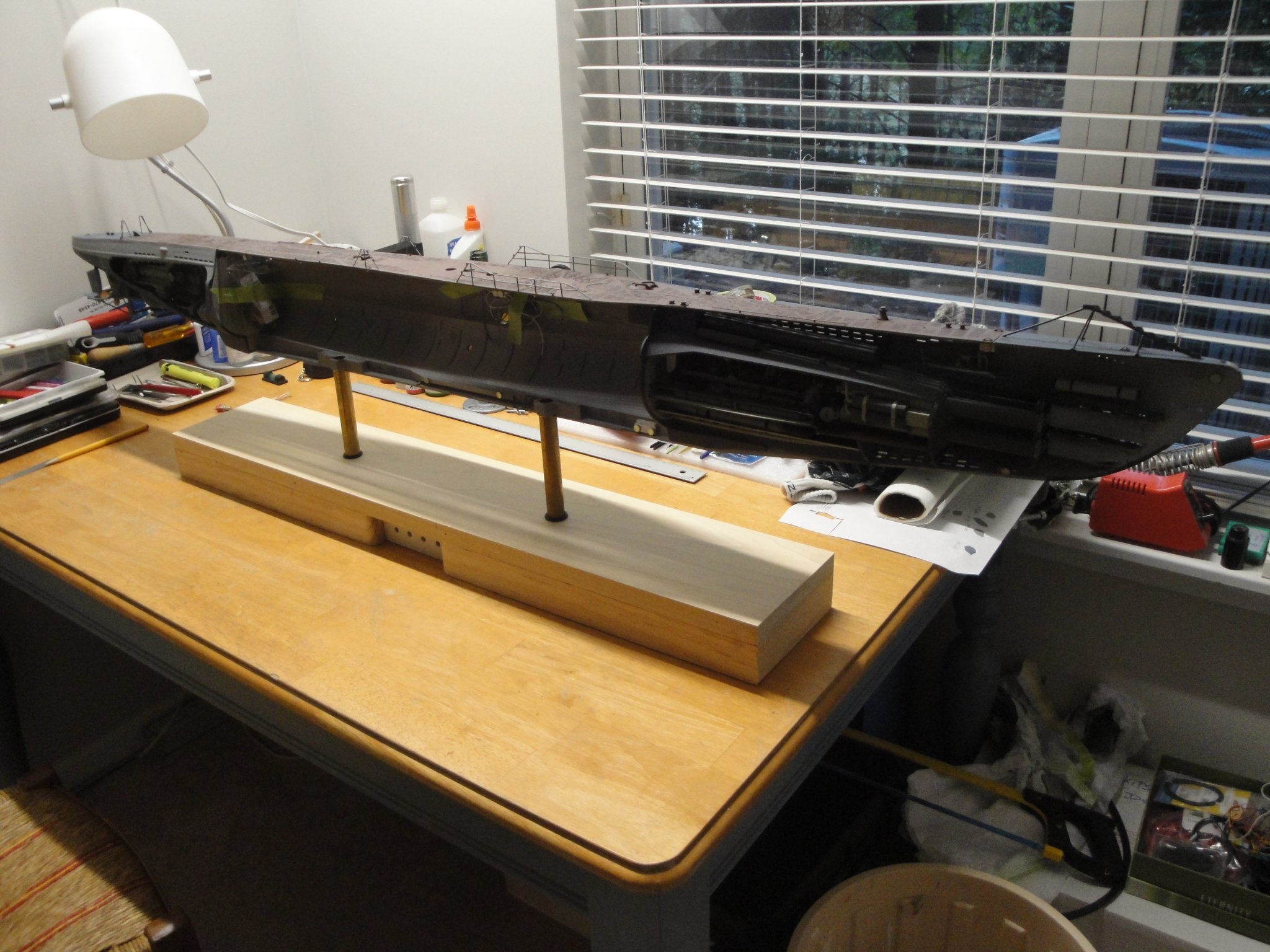
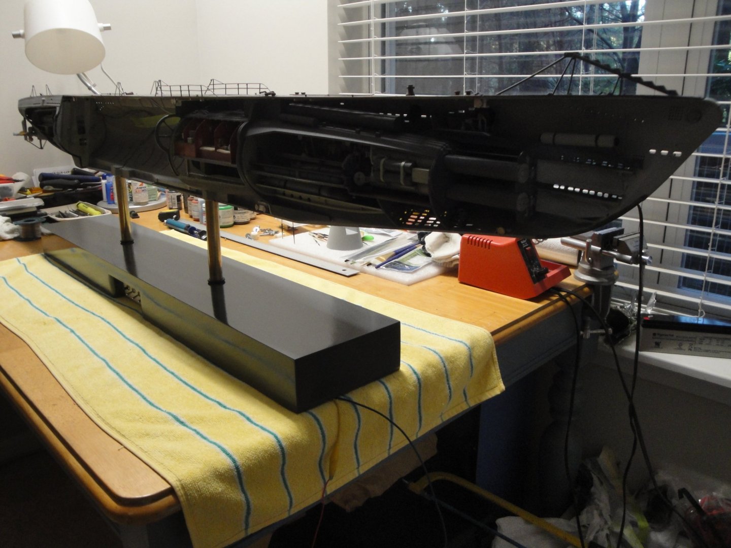
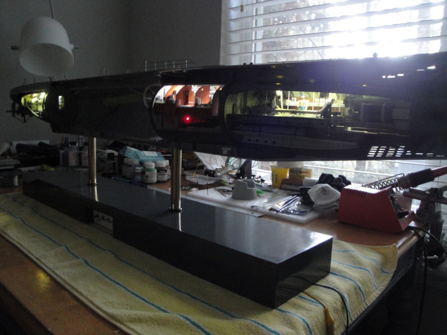
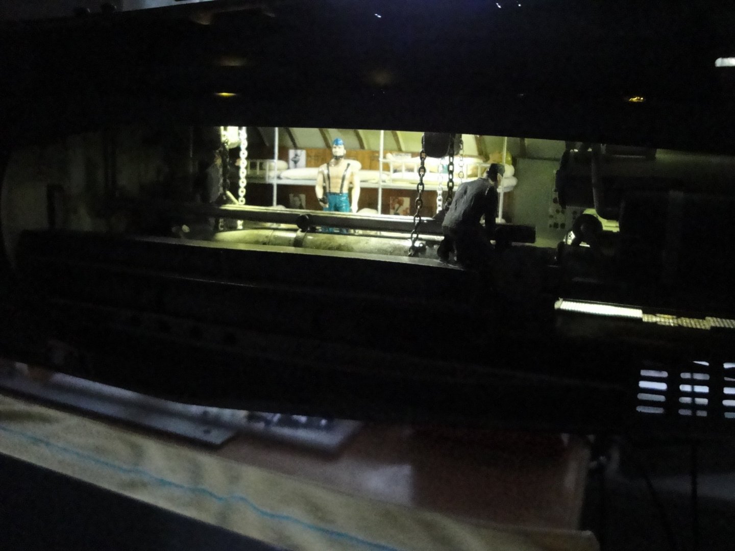
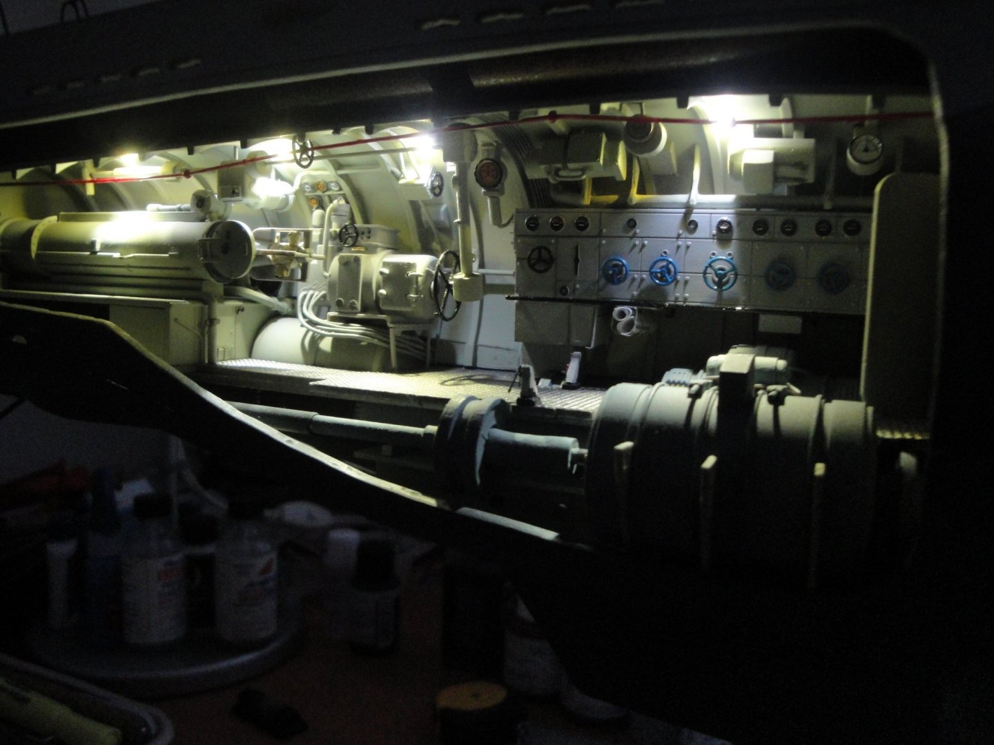
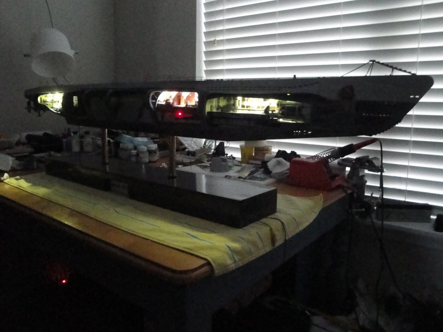
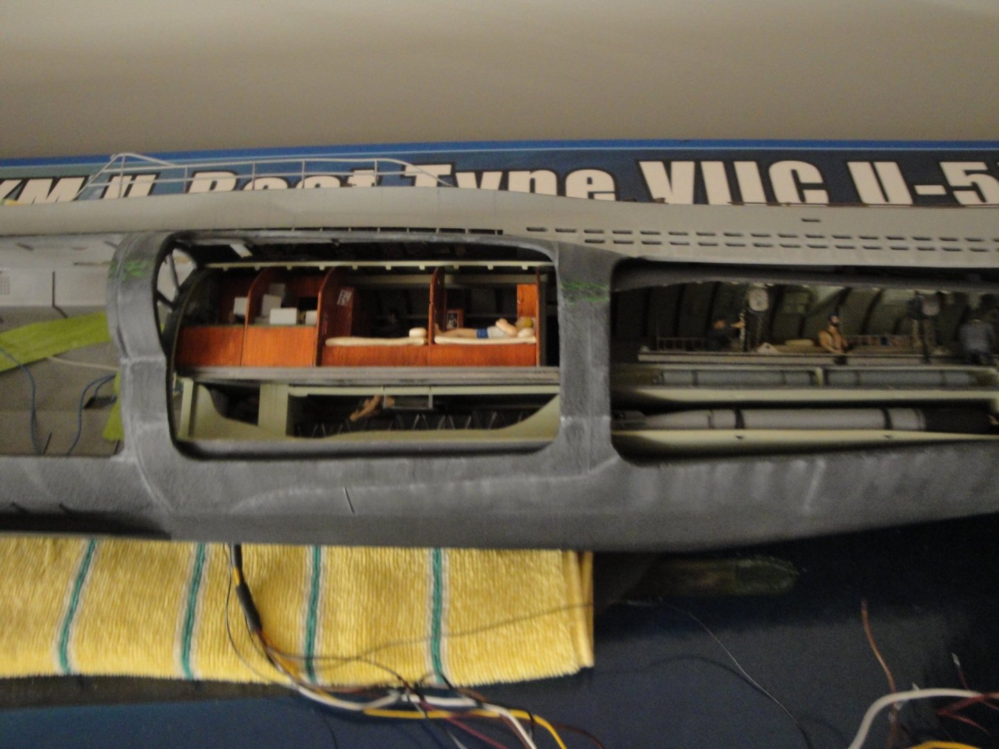
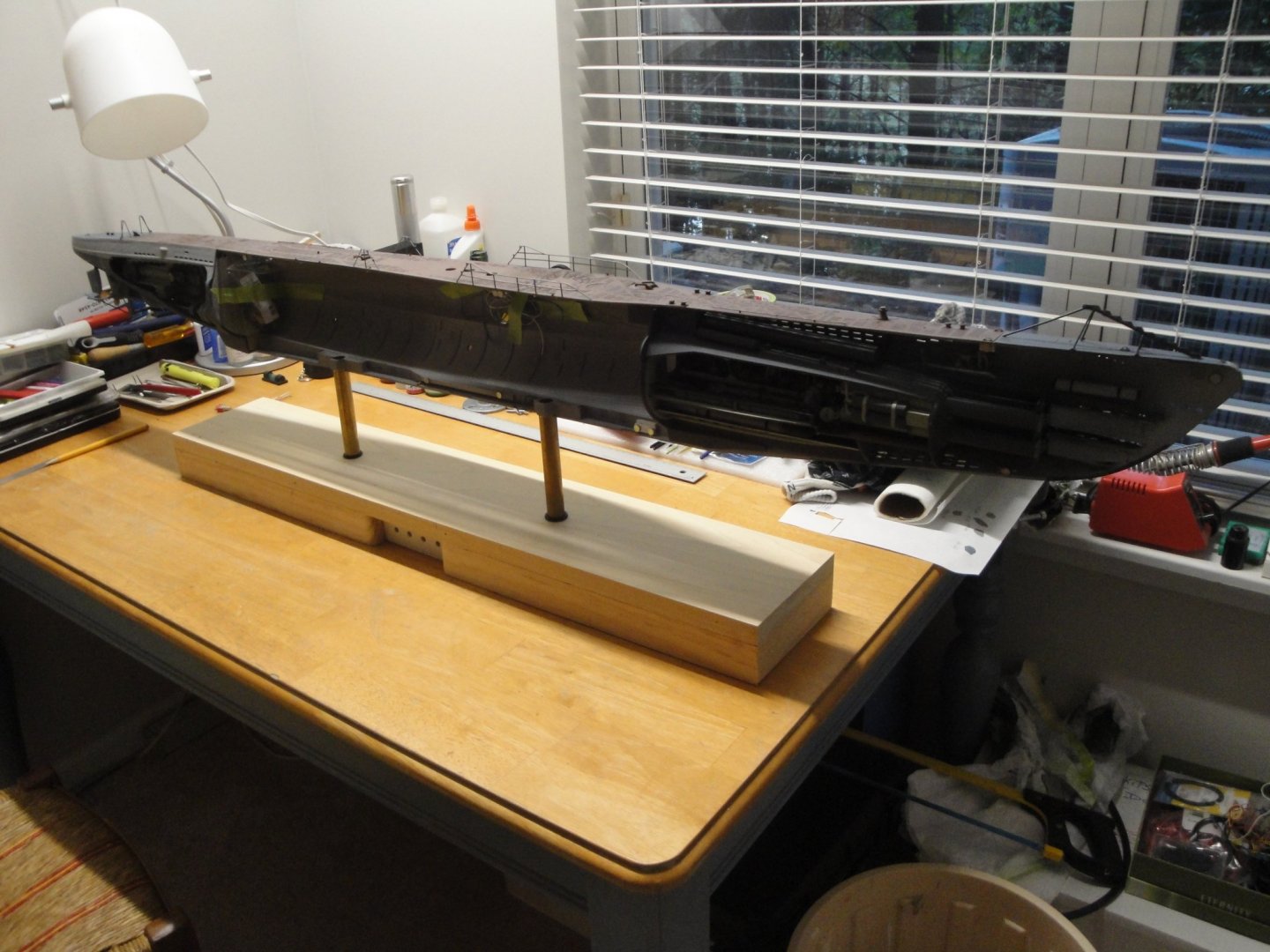
Going through the wiring (relatively complex) of the lights and features of the submarine. The stands are made of usual plumbing parts and provide a stable base for that heavy model. I have finished wiring the torpedo compartments and the officer's quarters. All the connections have small connectors to allow me to take the whole enchilada apart. I suspect that the building of the remaining compartments and the conning tower may require an easier access to the hull and therefore, it is swell to be able to disassociate it from the base. The result is quite impressive and massive: Close up on the radio equipment and batteries compartment: The hull as it stands today: Close-up on the various compartments: All buttoned up: Hope you enjoy that night tour of the insides of a German U-boot. Yves


- 760 replies
-
- 30
-
-
Usually, masking tape has to be removed when the paint is still fresh and not cured. By waiting, the paint may go in pieces and crumbs, when you remove the tape. Yves
-
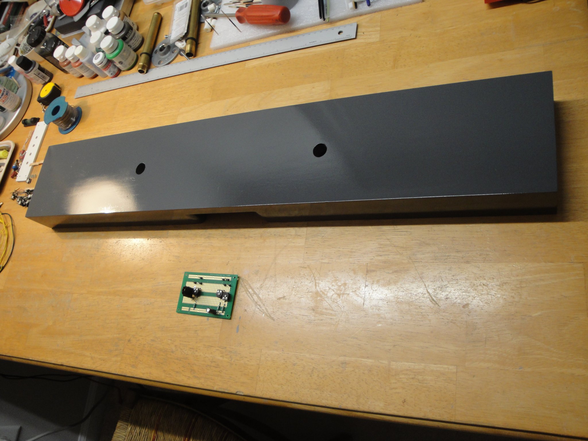
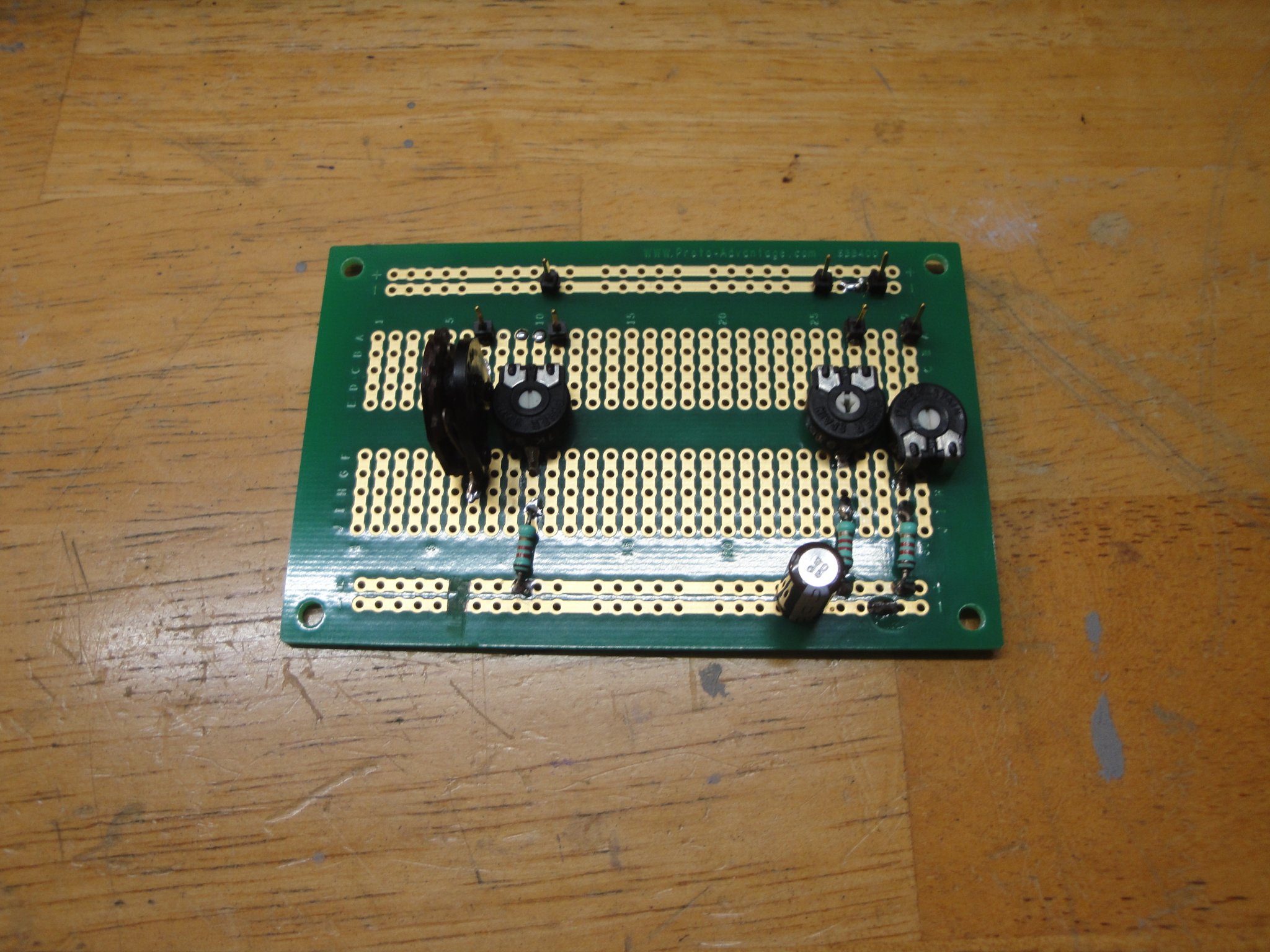
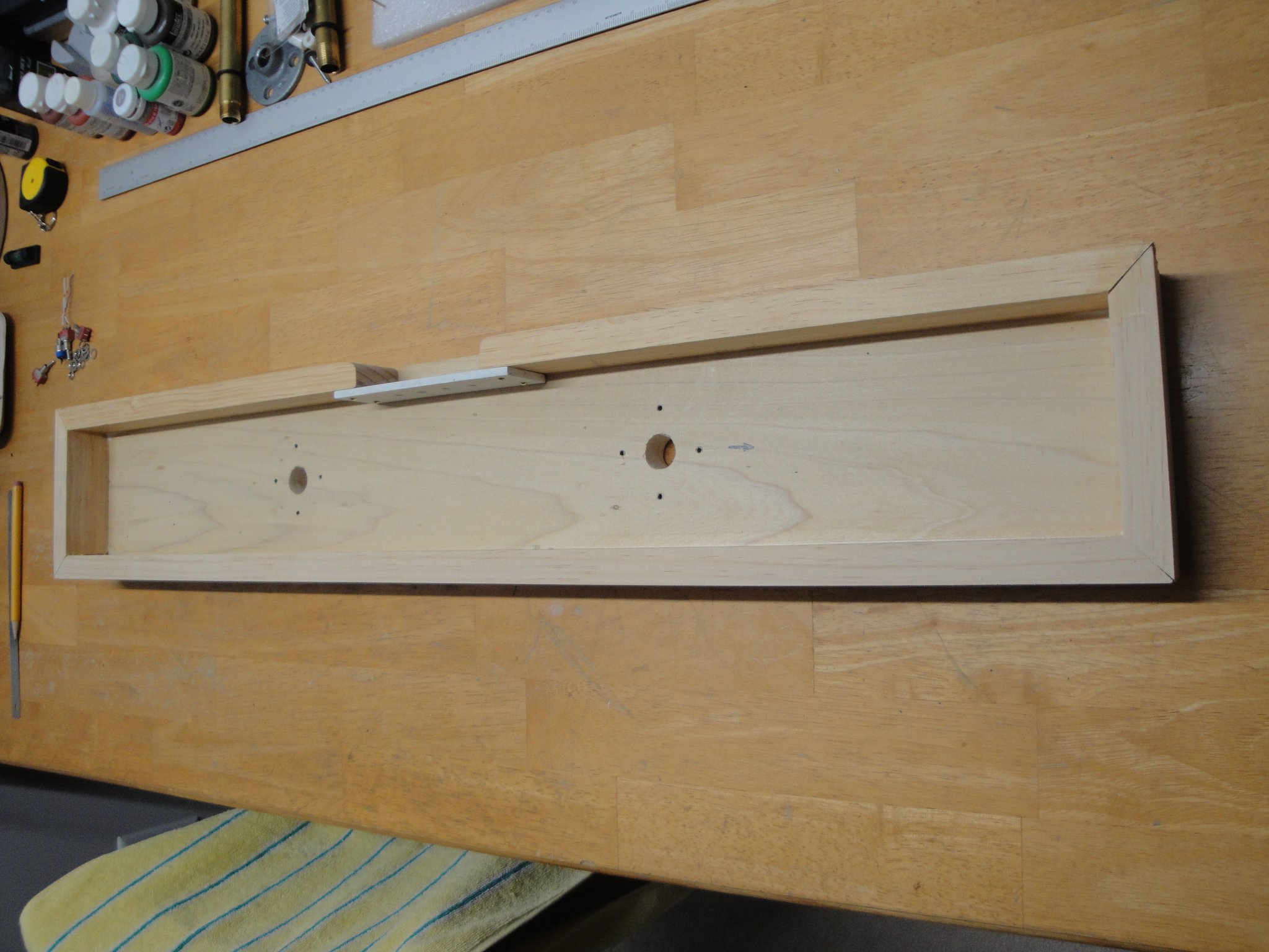
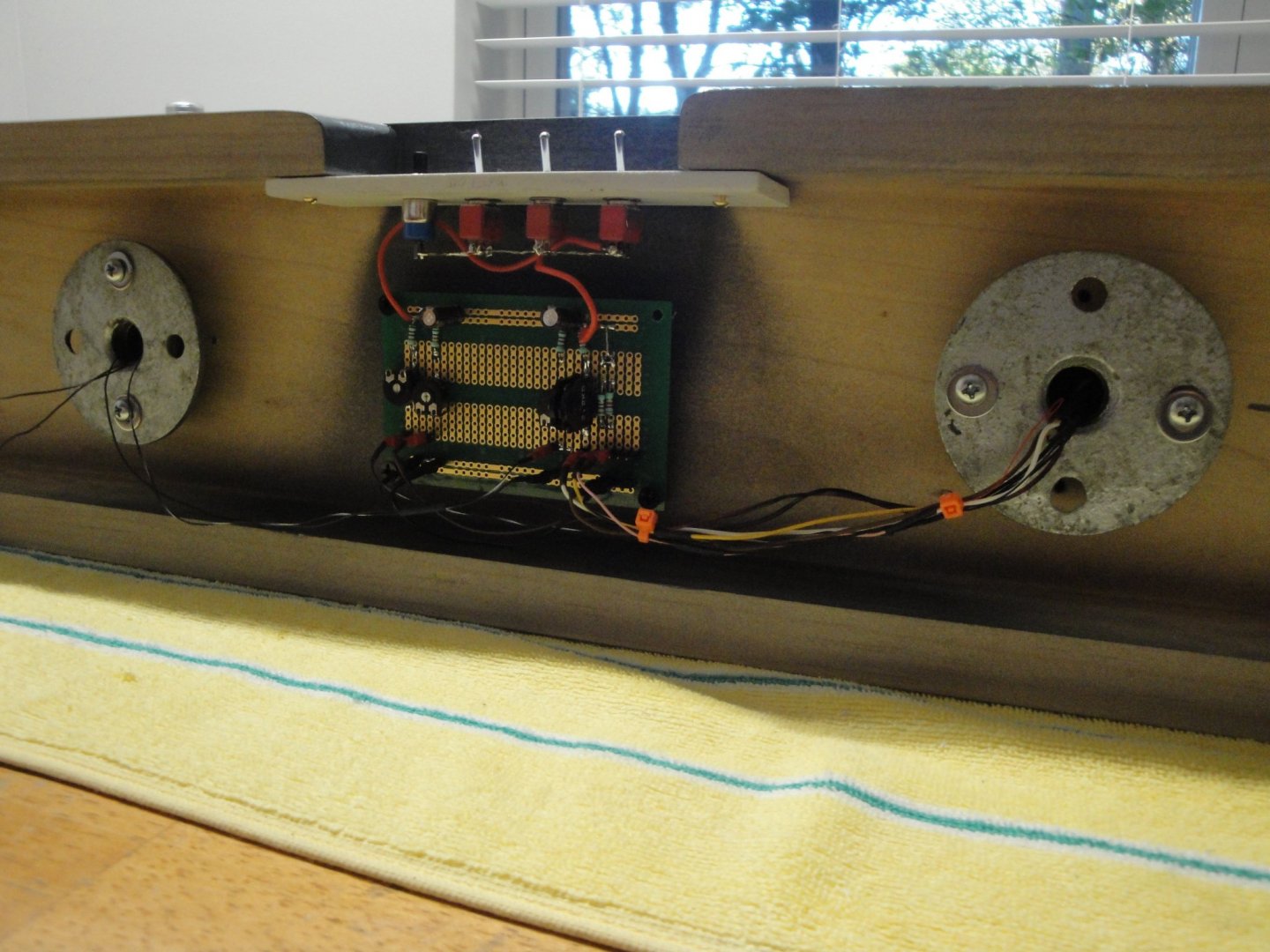
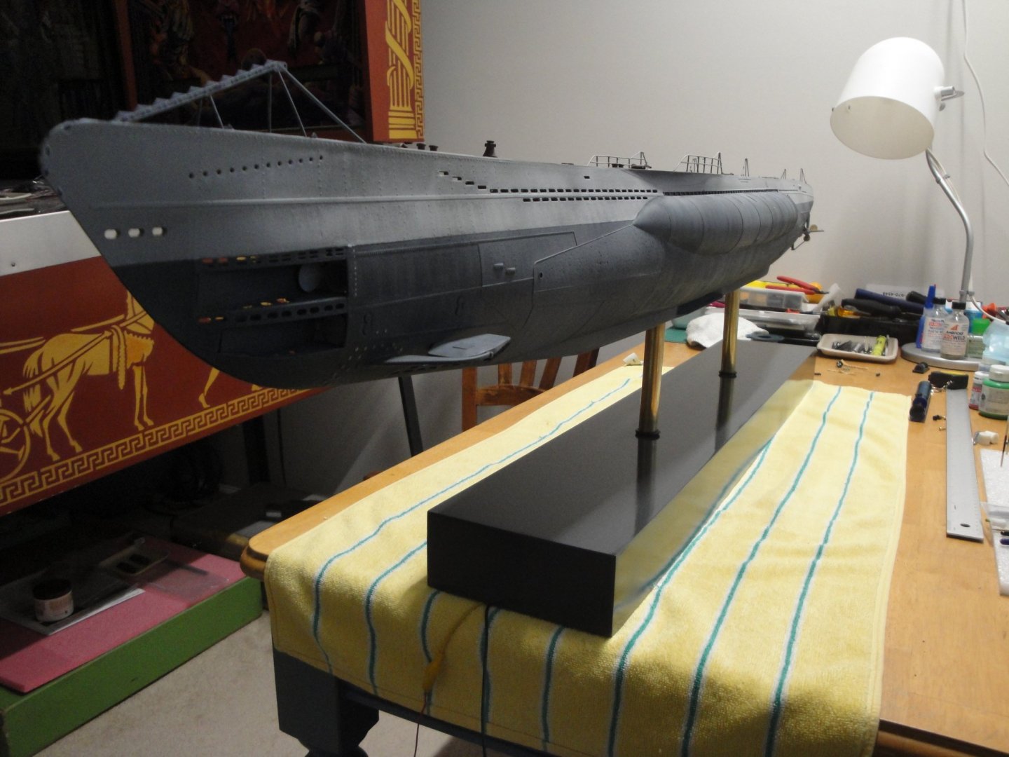
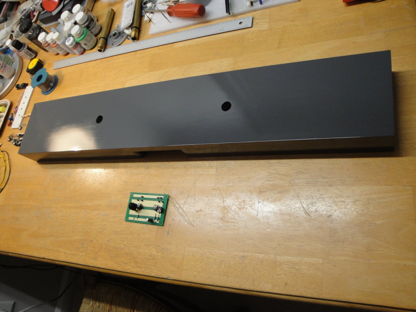
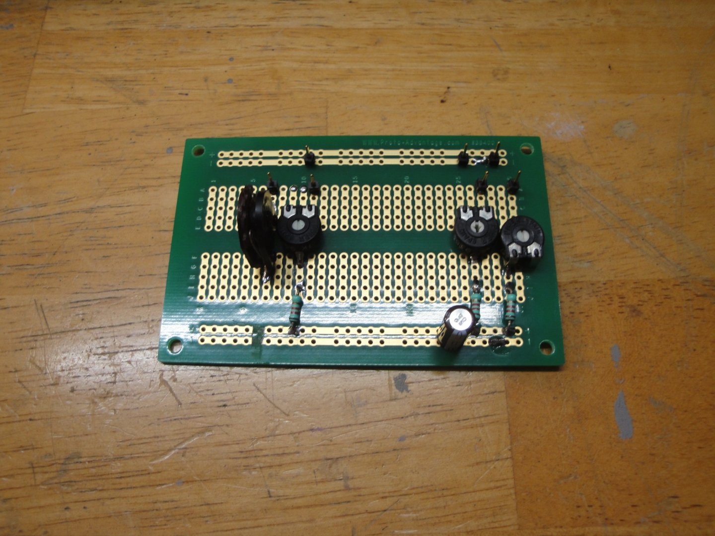
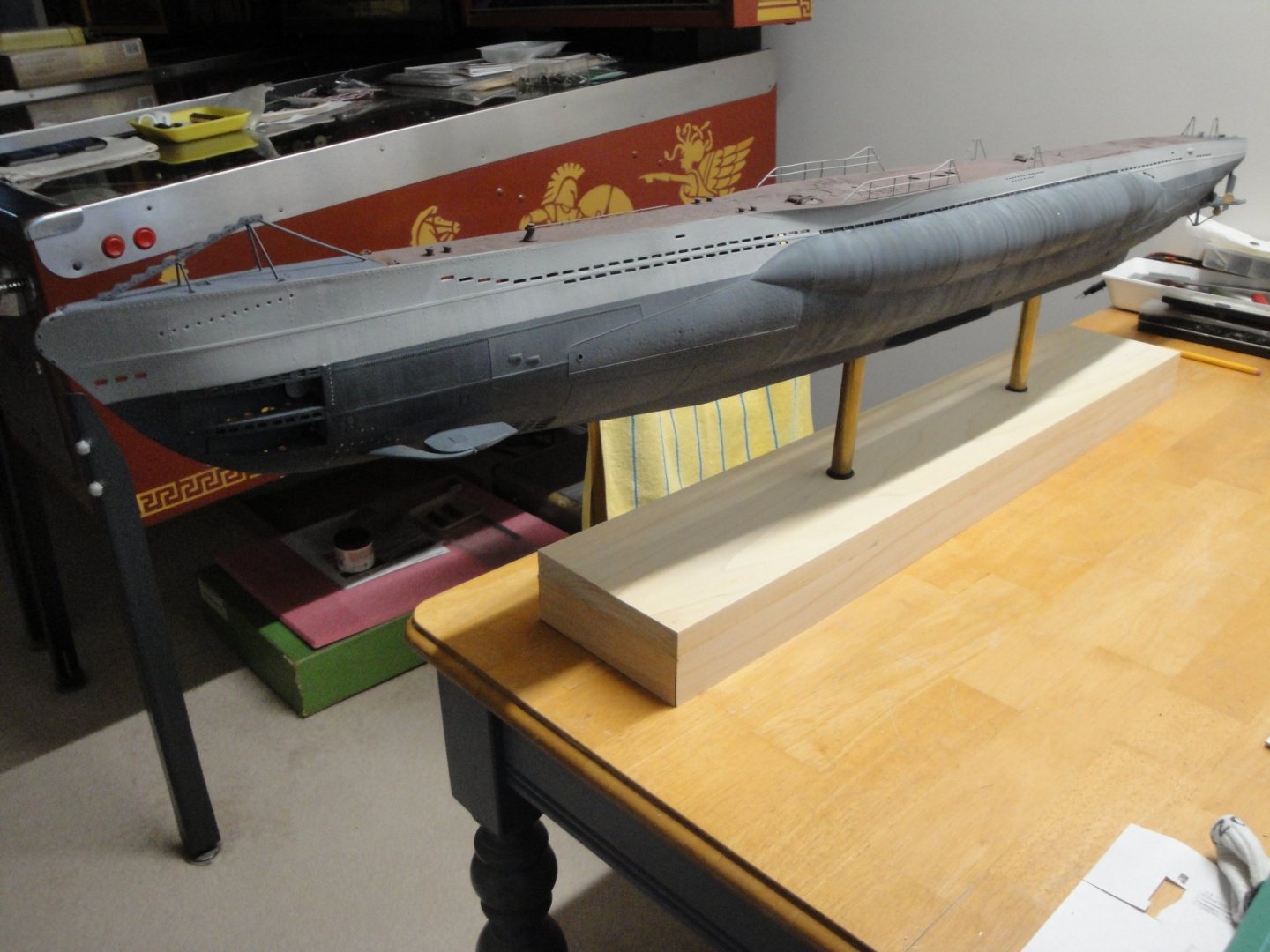
The base is close to completion. After three or four coats of primer, putty and sanding, I gave it an industrial look with a glossy dark gray. This will provide enough contrast with the matte aspect of the hull: I am also working on the electric wiring board to control independently all the lights. Adjustable resistors are used to fine tune the amount of light through each compartment. Finally, the Officers quarter has been glued into the hull, and the wires inserted through the stand receptacle: I am going to use small connectors to allow the capability to remove the hull from the stand, in case of maintenance and during the building of the three remaining modules. Yves
- 760 replies
-
- 13
-
-
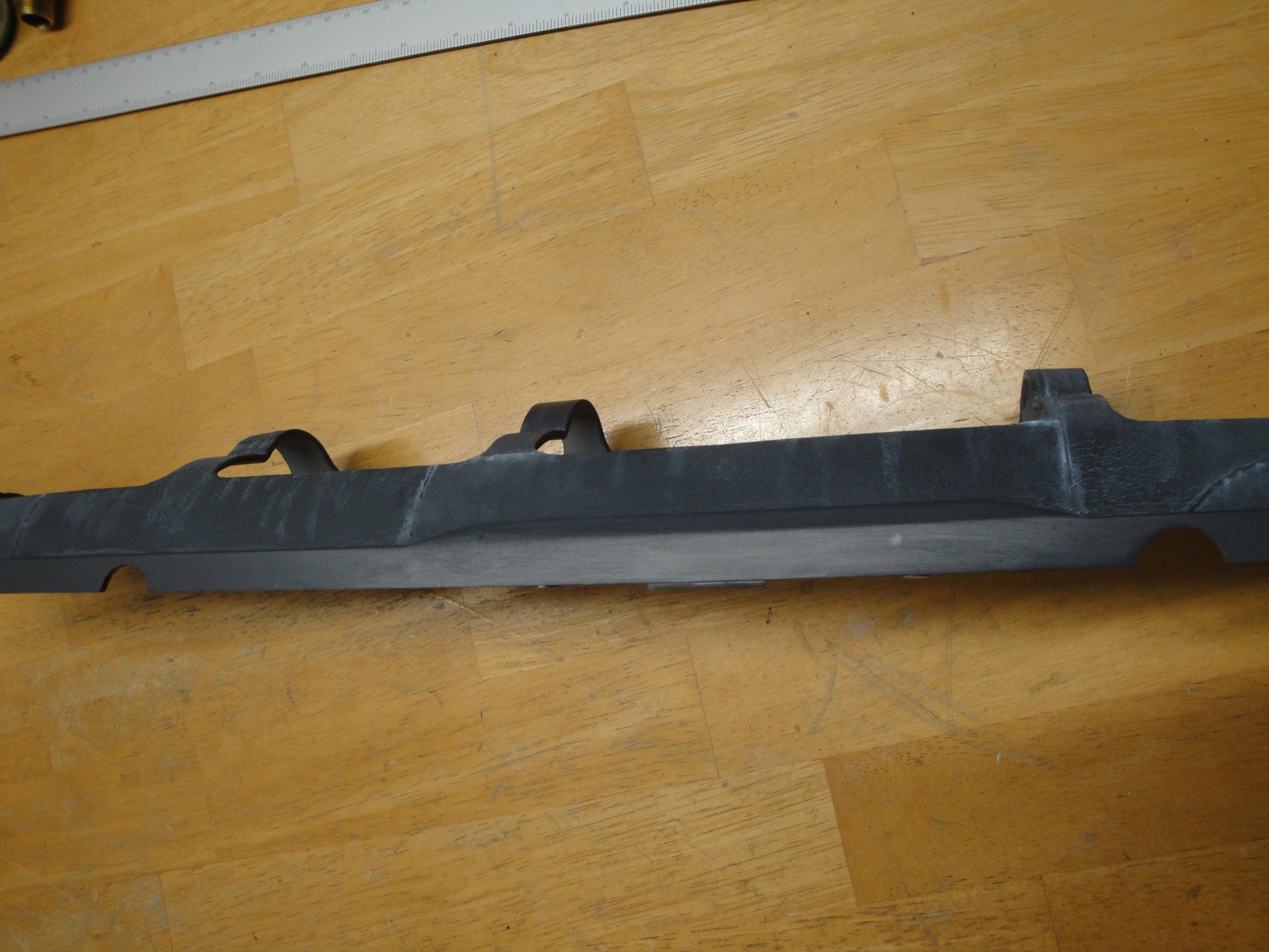
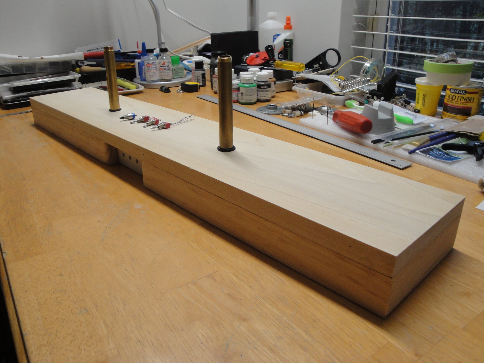
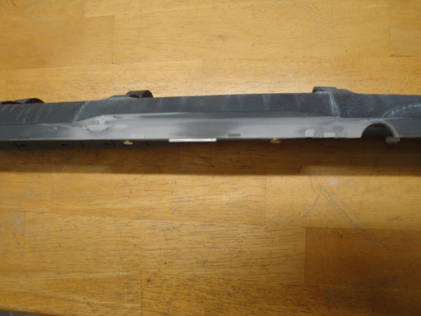
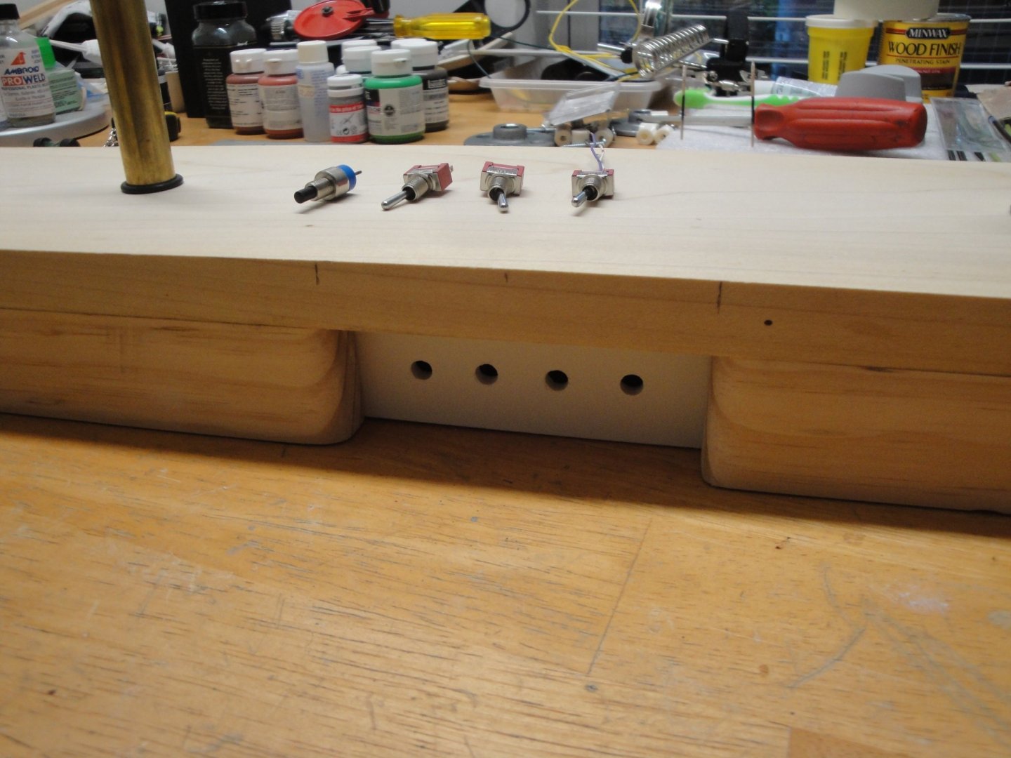
After a few weeks off, it is time to resume our build. First, I had to fix the lower part of the keel. Trumpeter designed a few slots to allow the passing of electrical wires. That does not apply to me, since all electrical connections will go through the brass tube supporting the model. So putty and paint: I will have to repaint the other side of the hull, and finalize with a soft weathering. Next, I have been working on the stand for this large and very heavy model. I need to have room for a few switches and for the various resistors that will allow me to fine tune the intensity of the various LED circuits. I wish to have an harmonious amount of light throughout the vessel. Building a thick base was the best way to go. That base can later on be installed in a larger display case, although it is unlikely it will ever happen. I will show how the tubes are secured in a future picture. It is a heavy duty assembly. No jokes. The panel for all the switches: - Push button for the propulsion motors. - One switch for the outside lights (rear, top of the sail, positions lights). - One switch for the internal light, through the six compartments. - One switch for the special lights (battery enclosure, equipment dials.....etc). This will give you some ideas of the massive assembly: I thought about gluing some precious woods on that base. The base is 32 inches by 6 ..... After going to my local Woodwork shop and being horrified by the price of a piece of wood large enough to cover the top, I have decided to instead paint the base and give it a little bit of an industrial look. I will use a sander and multiple coats of primer to obtain as smooth as possible of a finish and probably paint the base. Not sure which color yet.... Yves


- 760 replies
-
- 16
-
-
Fantastic videos. A nice display of multiple technologies, from the camera all the way to the submarine and torpedoes. Yeap, your neighbor has a very nice pond.... among other things. Yves
- 55 replies
-
- 2
-
-
- auguste piccard
- submarine
- (and 2 more)
-
Gorgeous carbon sails. I love the modern look that it offers, as compared to the traditional white Dacron. Yves