HOLIDAY DONATION DRIVE - SUPPORT MSW - DO YOUR PART TO KEEP THIS GREAT FORUM GOING!
×


yvesvidal
-
Posts
3,588 -
Joined
-
Last visited
Content Type
Profiles
Forums
Gallery
Events
Everything posted by yvesvidal
-
 Very interesting and so unusual model. Definitely worth realizing. Please post pictures of the 3D parts before assembly if you have them. It is always fun to look at them before and after assembly. Which scale are you shooting for? Oh, and the traditional question: are the parts (STL files) available from you, for a modicum? Yves
 -
Why not paint it soft white? British ships had a lot of the cabin walls, painted in soft white with blue frames. Yves
-
CaptainMac, I have the same kit in my stash and will follow with a lot of interests, your progress. Yes, the Chaperon by Model Shipways is definitely the most realistic kit proposed on the market as the Occre and other Spanish kits are offering woods which do not match what was used to build these paddle boats, in the USA. There are a few excellent realizations of the Chaperon on that forum, and I invite you to look into them for ideas and inspirations. Yves
- 23 replies
-
- 2
-

-
- sternwheeler
- Chaperon
- (and 3 more)
-
That's the beauty about 3D printing: scale up or scale down, at your leisure. Yves
-
stagecoach by kgstakes - FINISHED - 1/8th scale
yvesvidal replied to kgstakes's topic in Non-ship/categorised builds
Absolutely superb. It looks super realistic and I love the work you did on the wheels and seats. Yves -
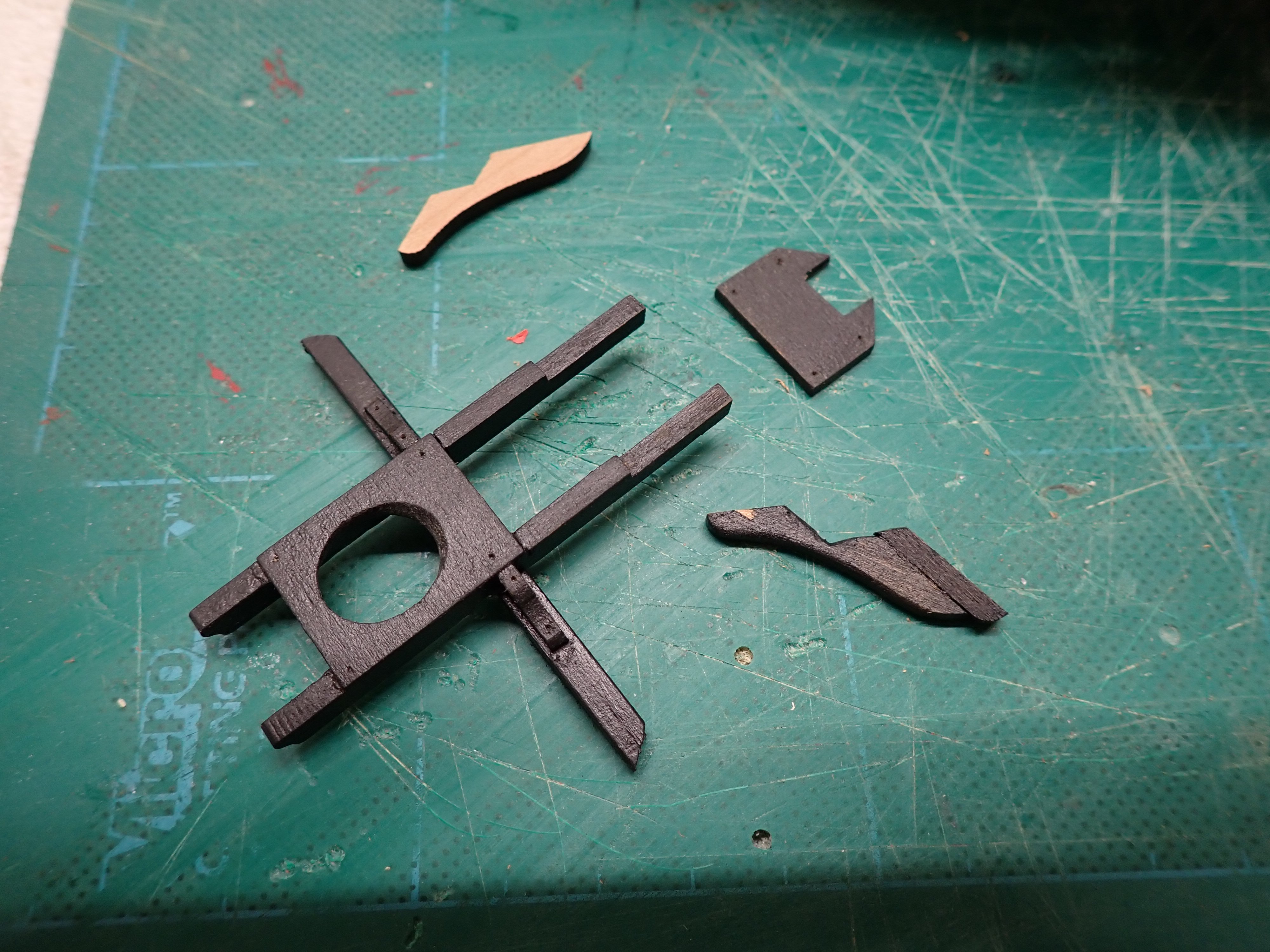
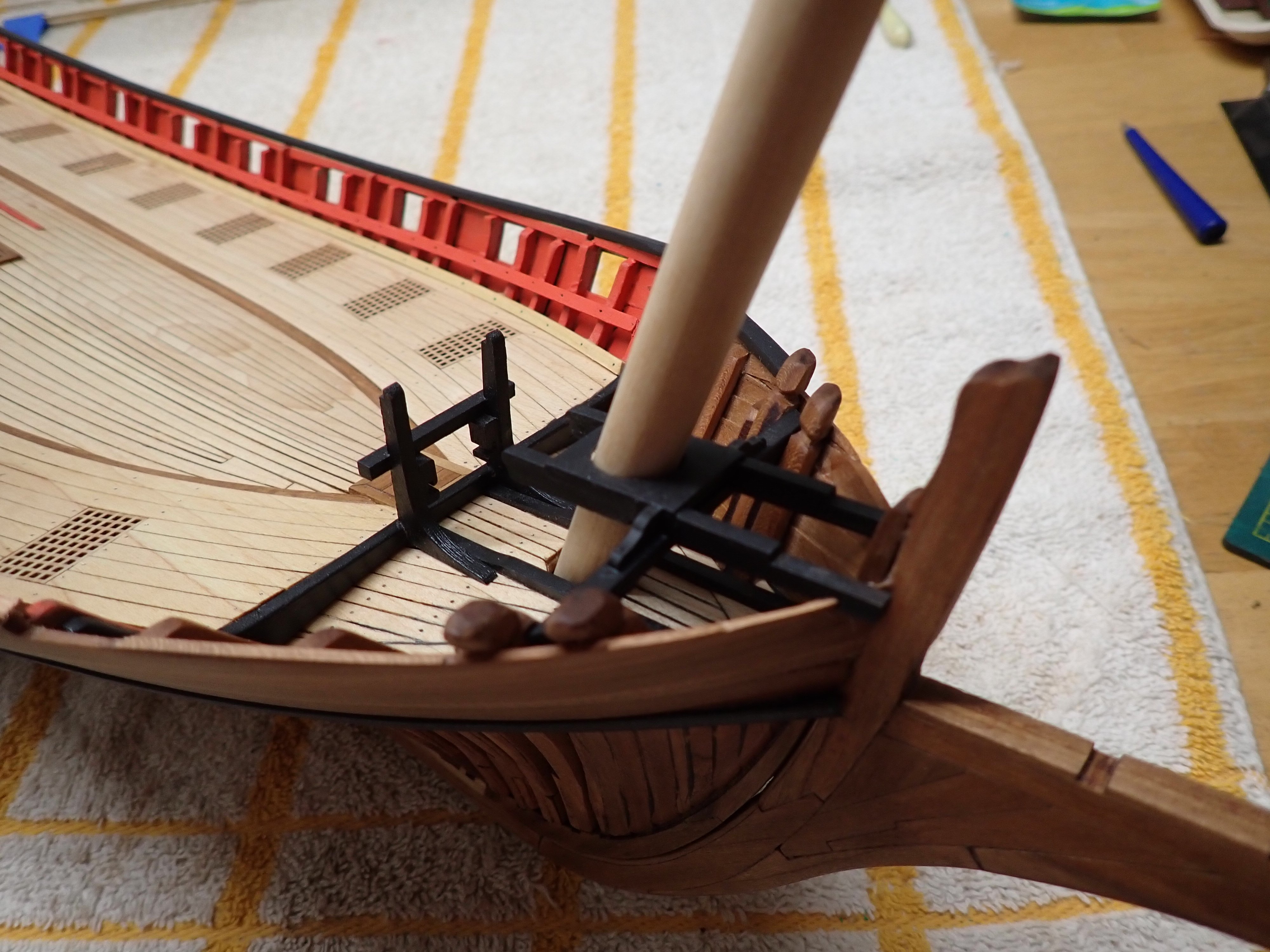
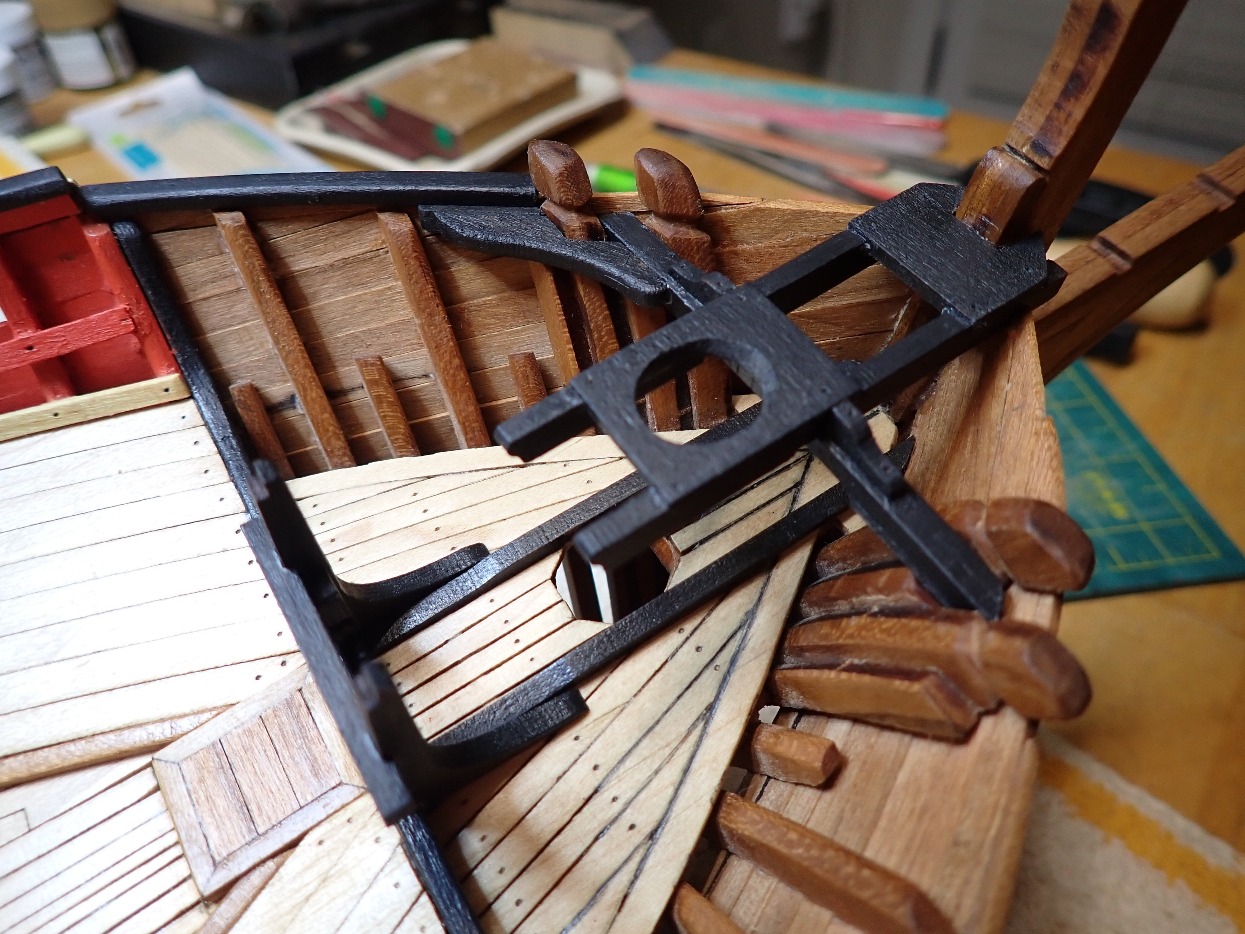
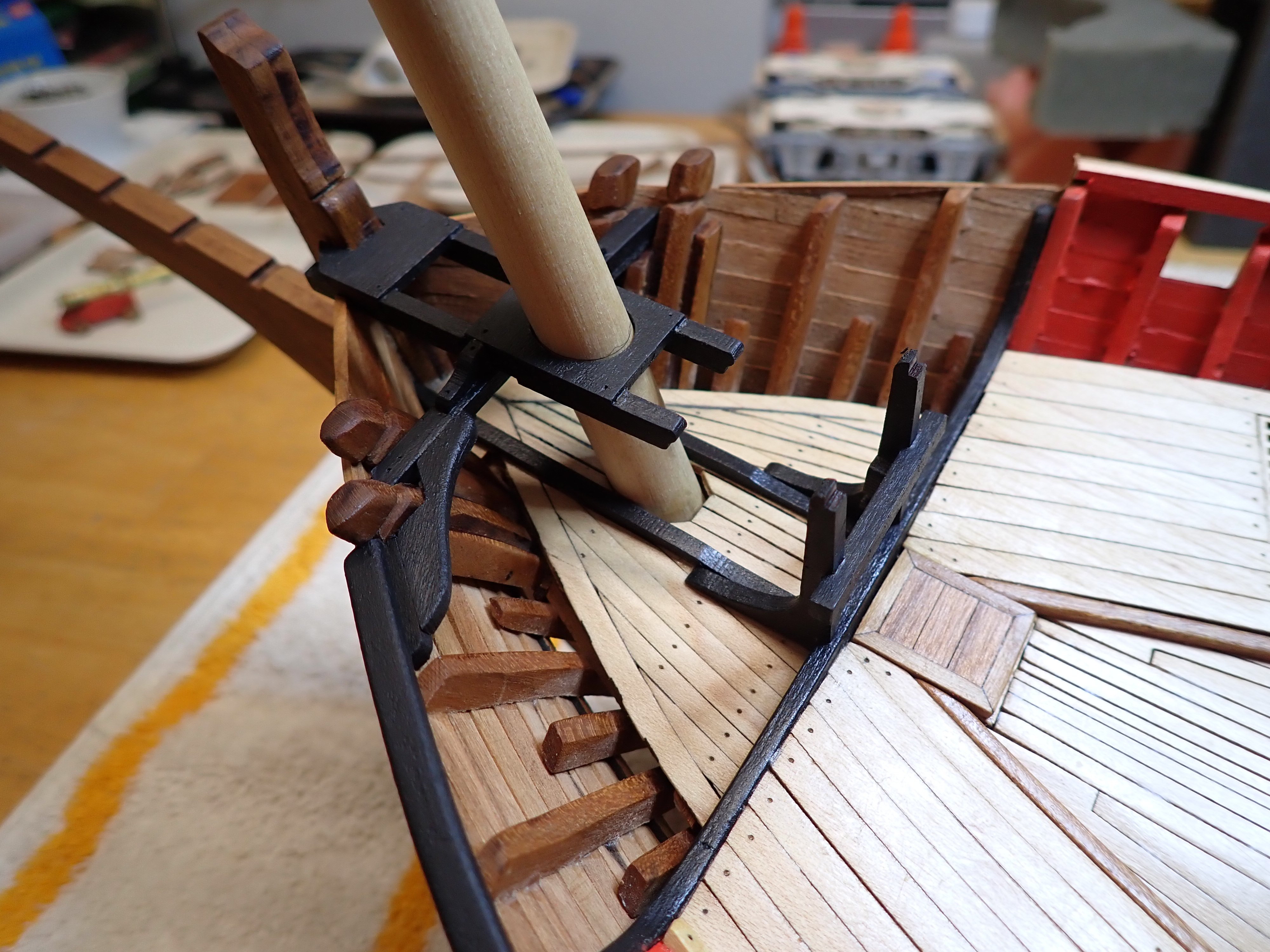
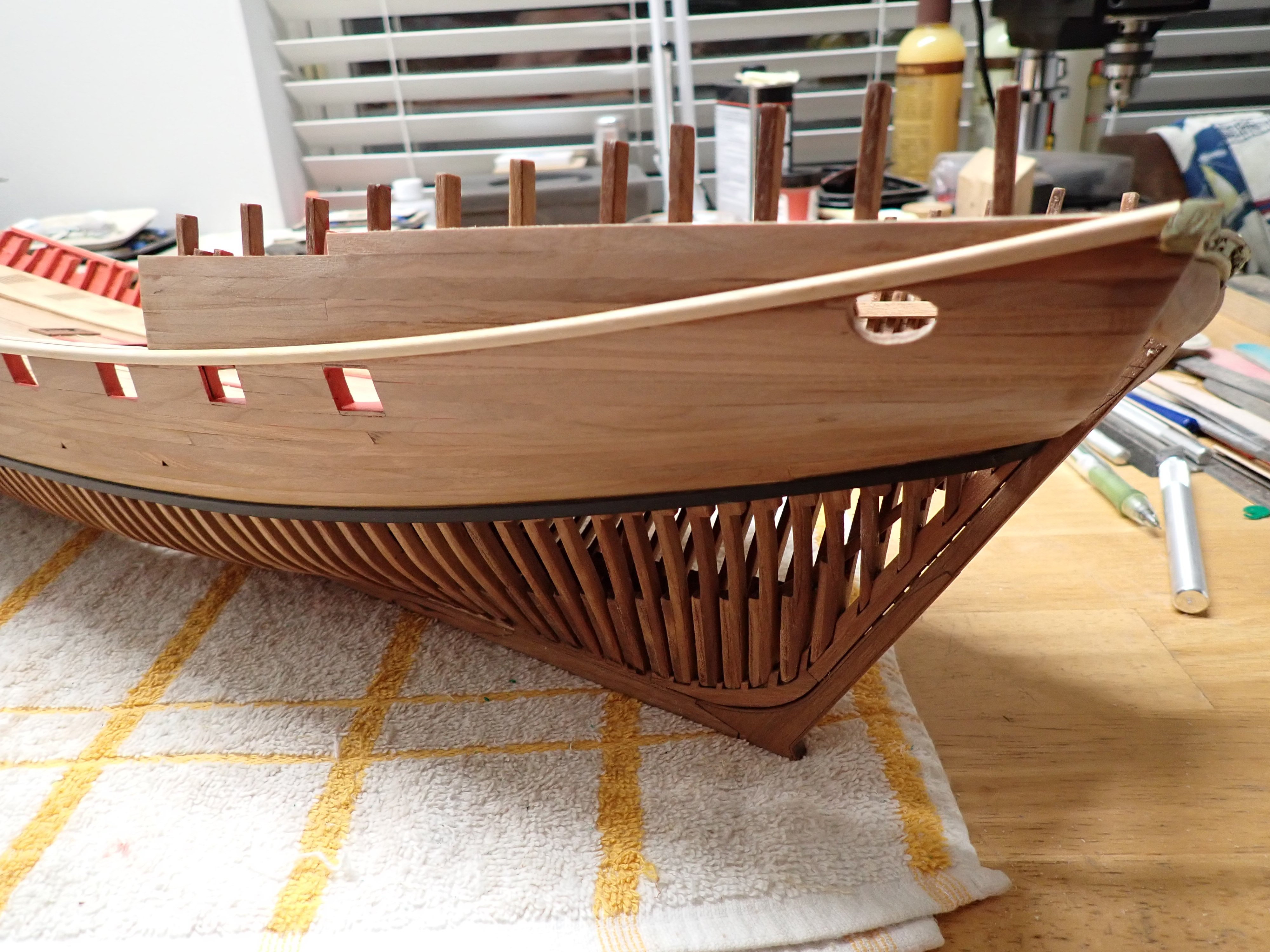
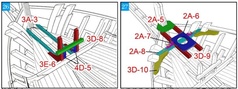
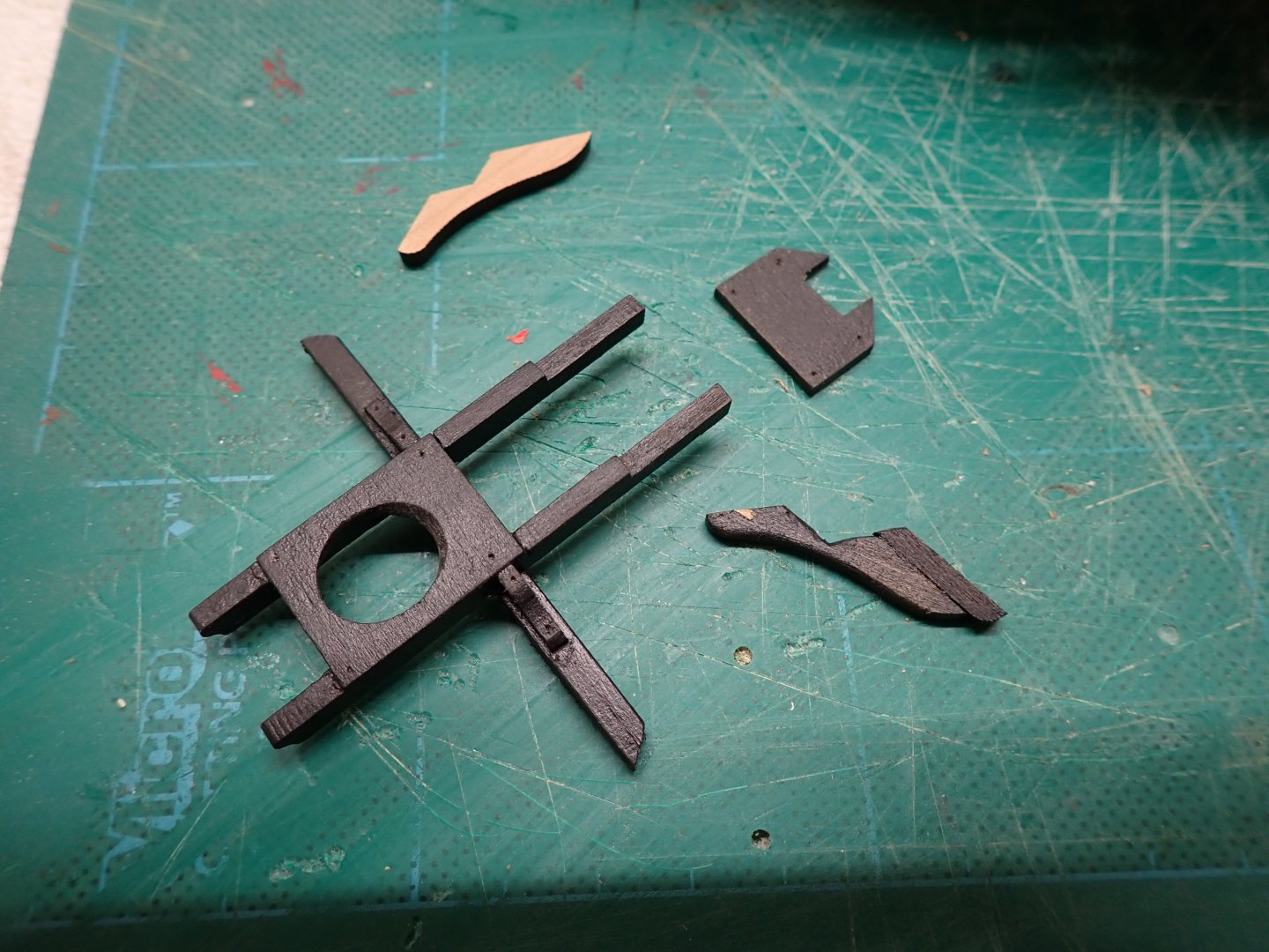
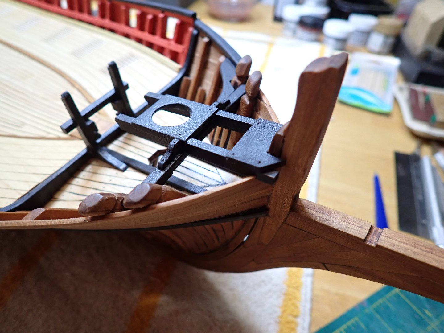
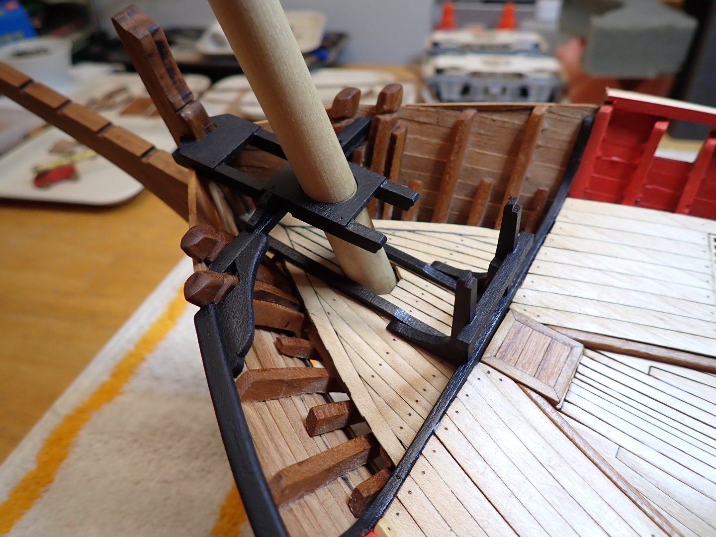
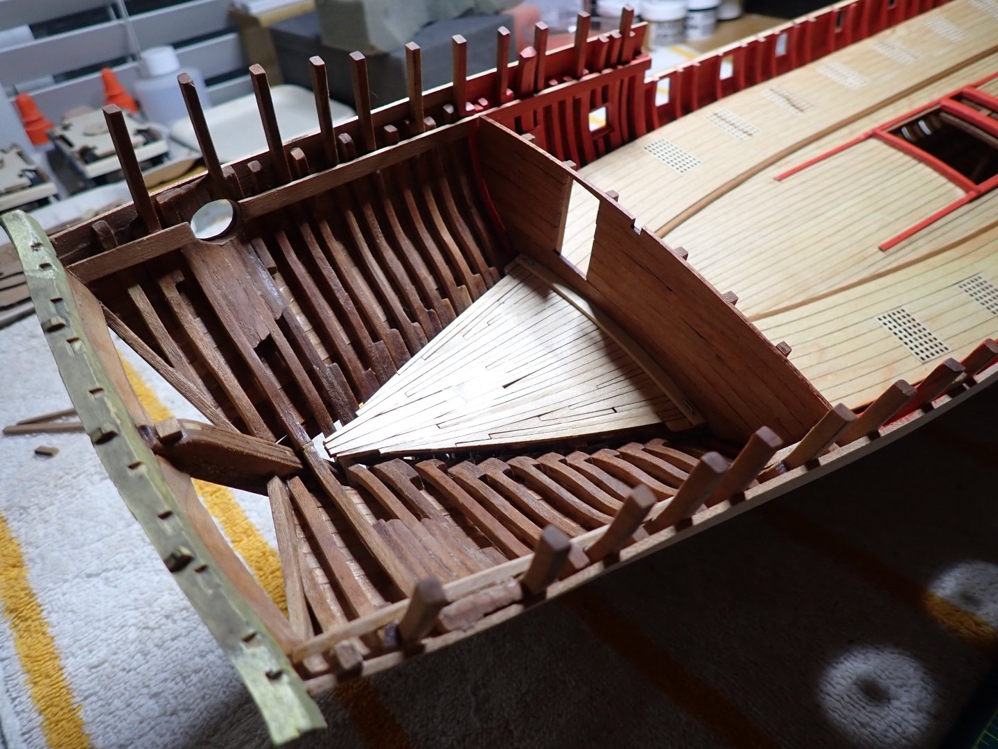
Working on the bow for a change of pace, and to see some details and progress: these parts are like little kits in themselves: The position of the front mast has to be carefully done, both laterally and longitudinally, to respect the 20 degrees angle: I will finish the other side, after installing the front rail (starboard side). I hope you enjoy these little progress. It is very enjoyable to build and adjust precisely. Yves


- 185 replies
-
- 17
-
-
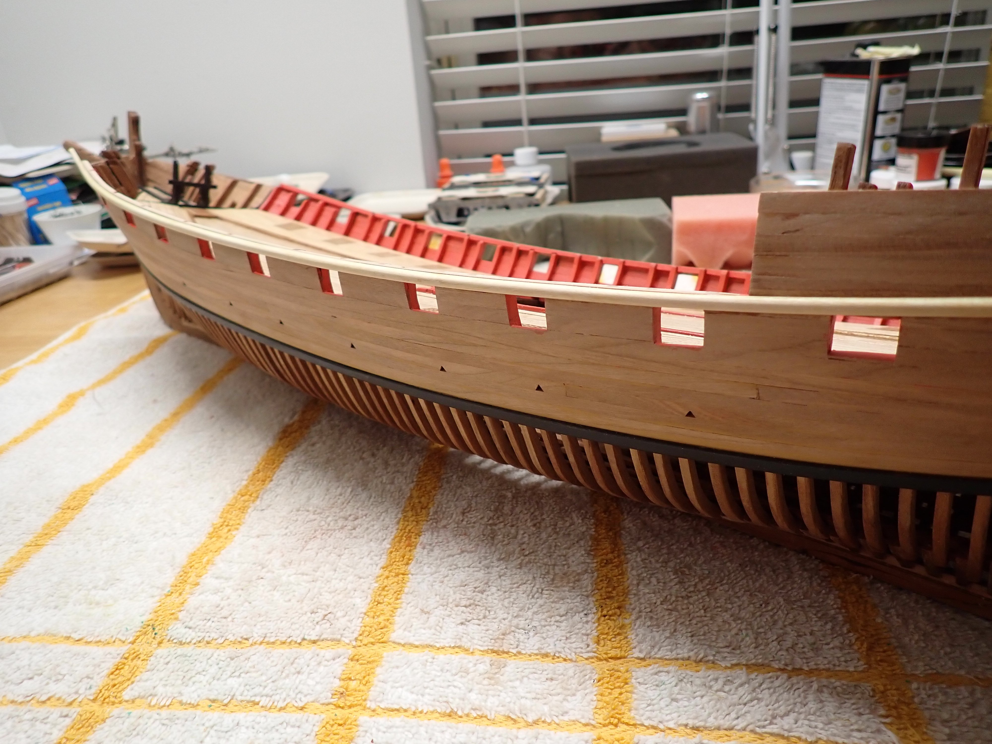
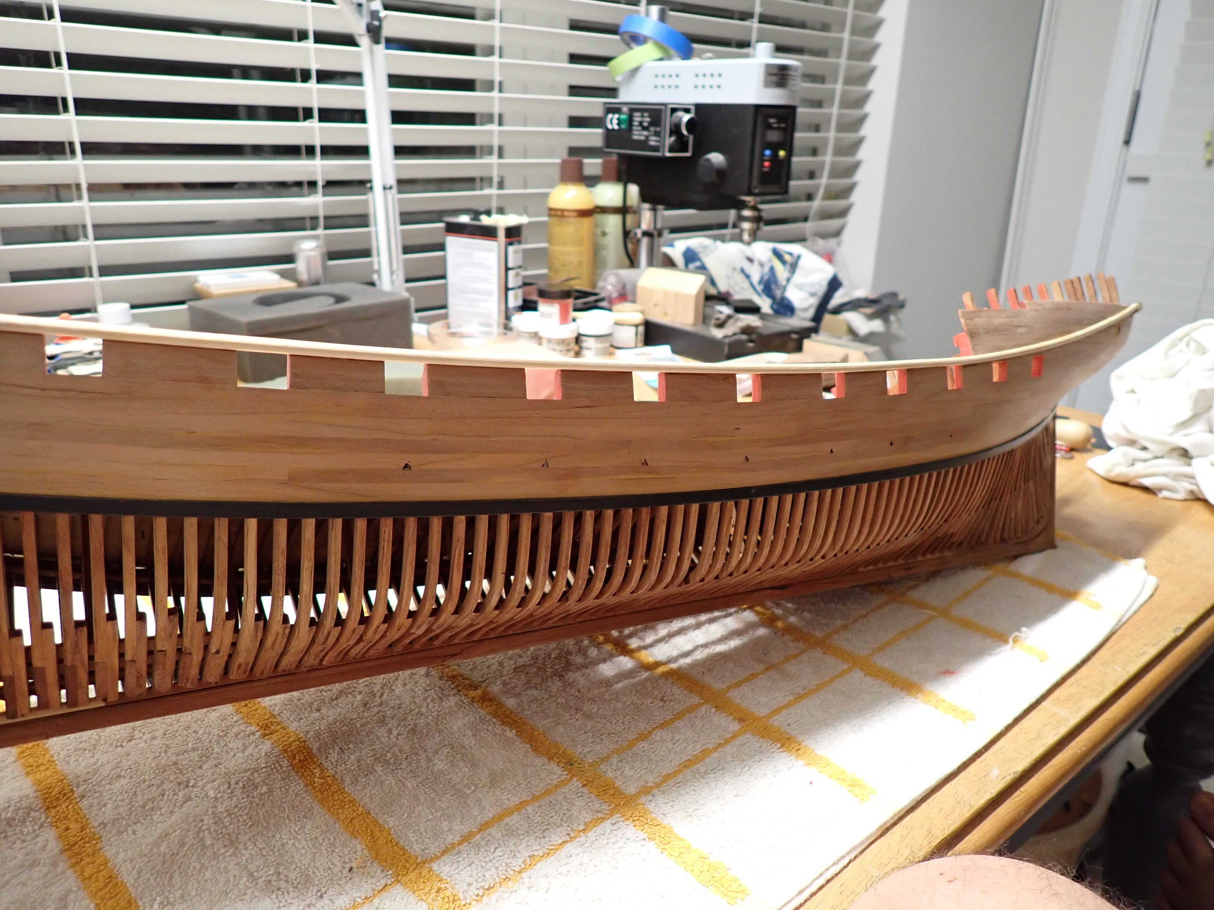
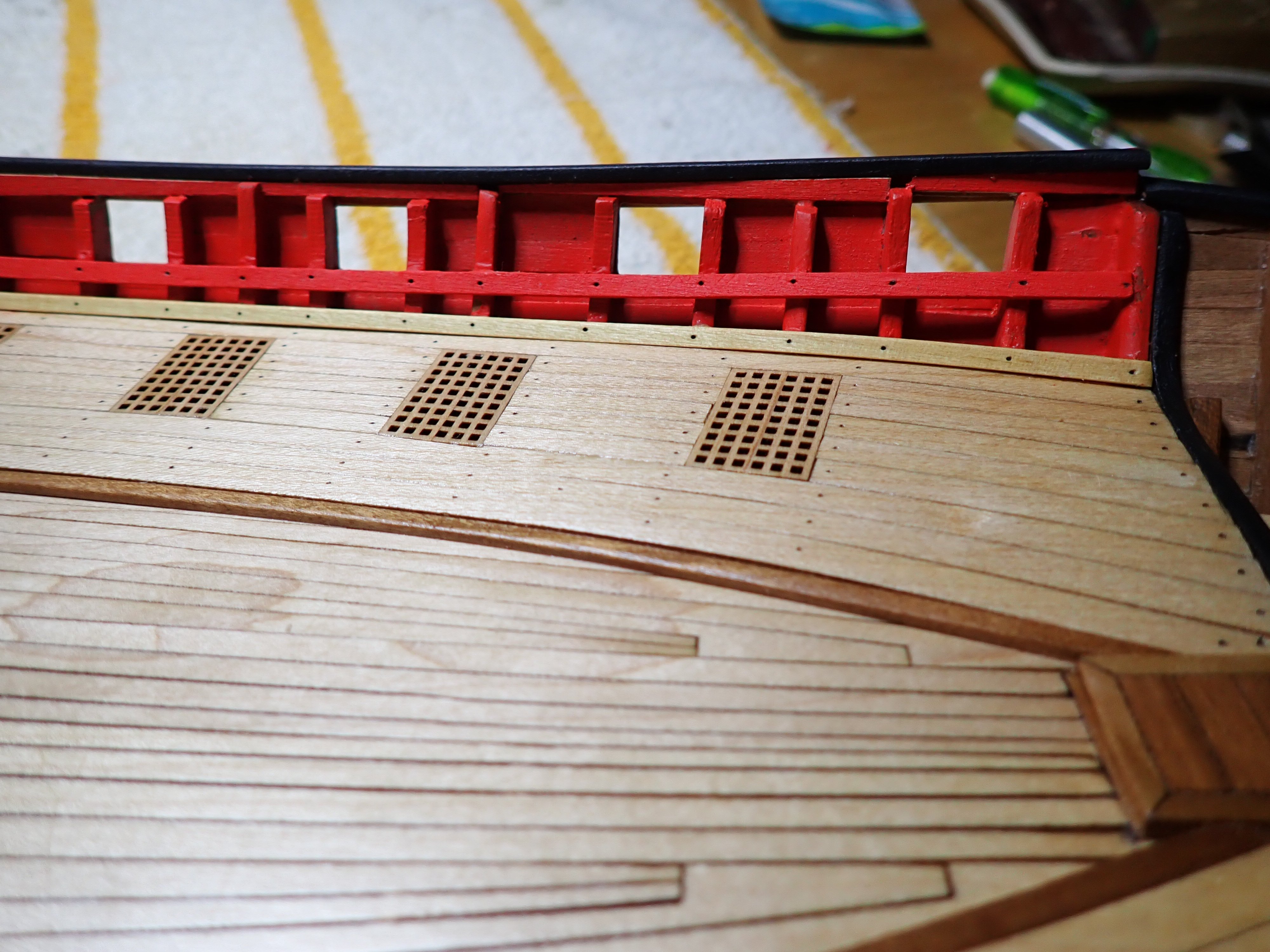
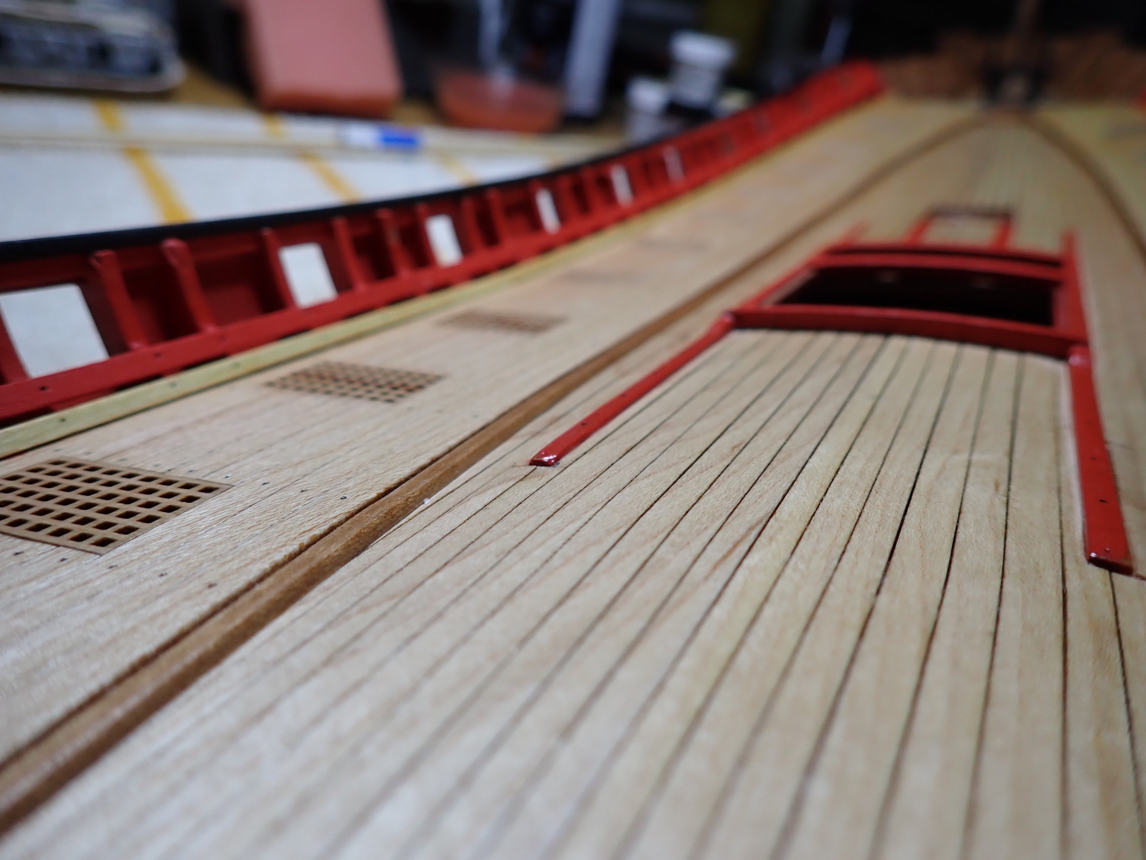
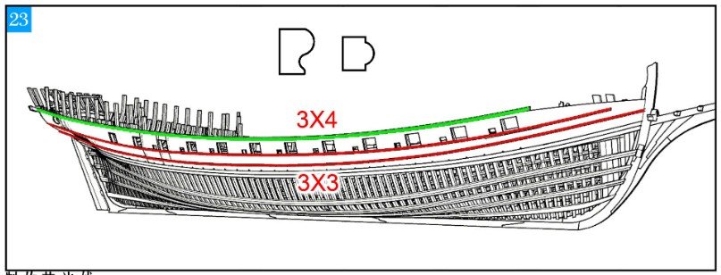
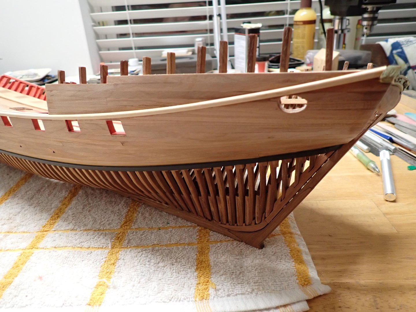
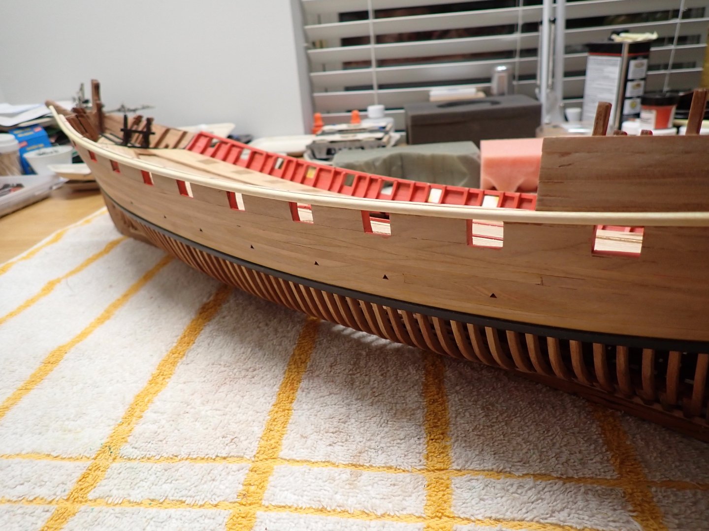
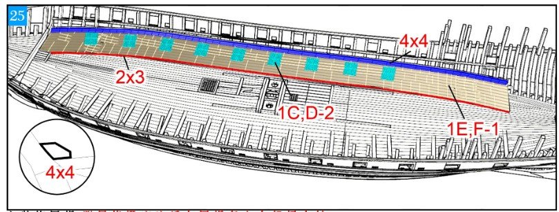
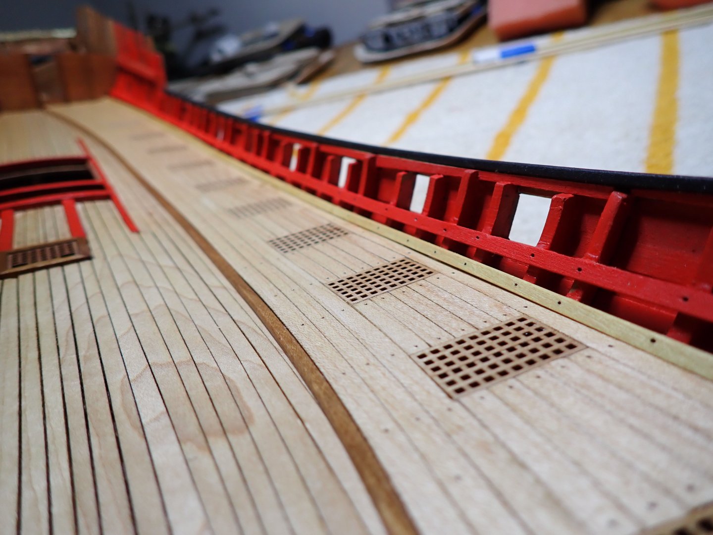
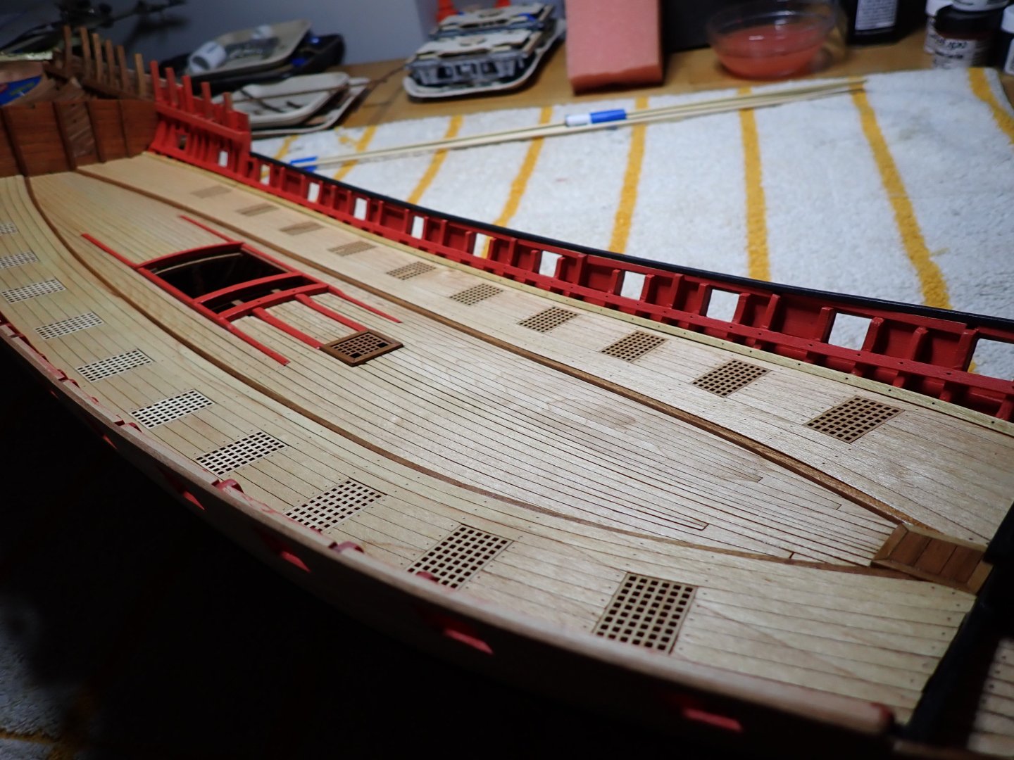
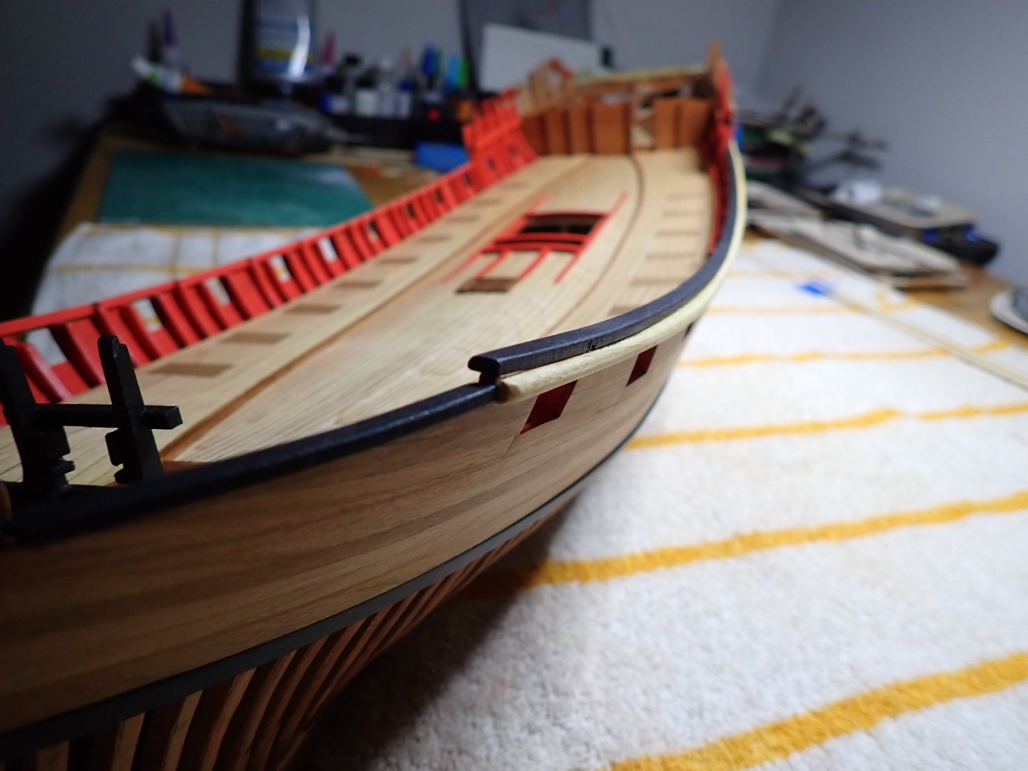
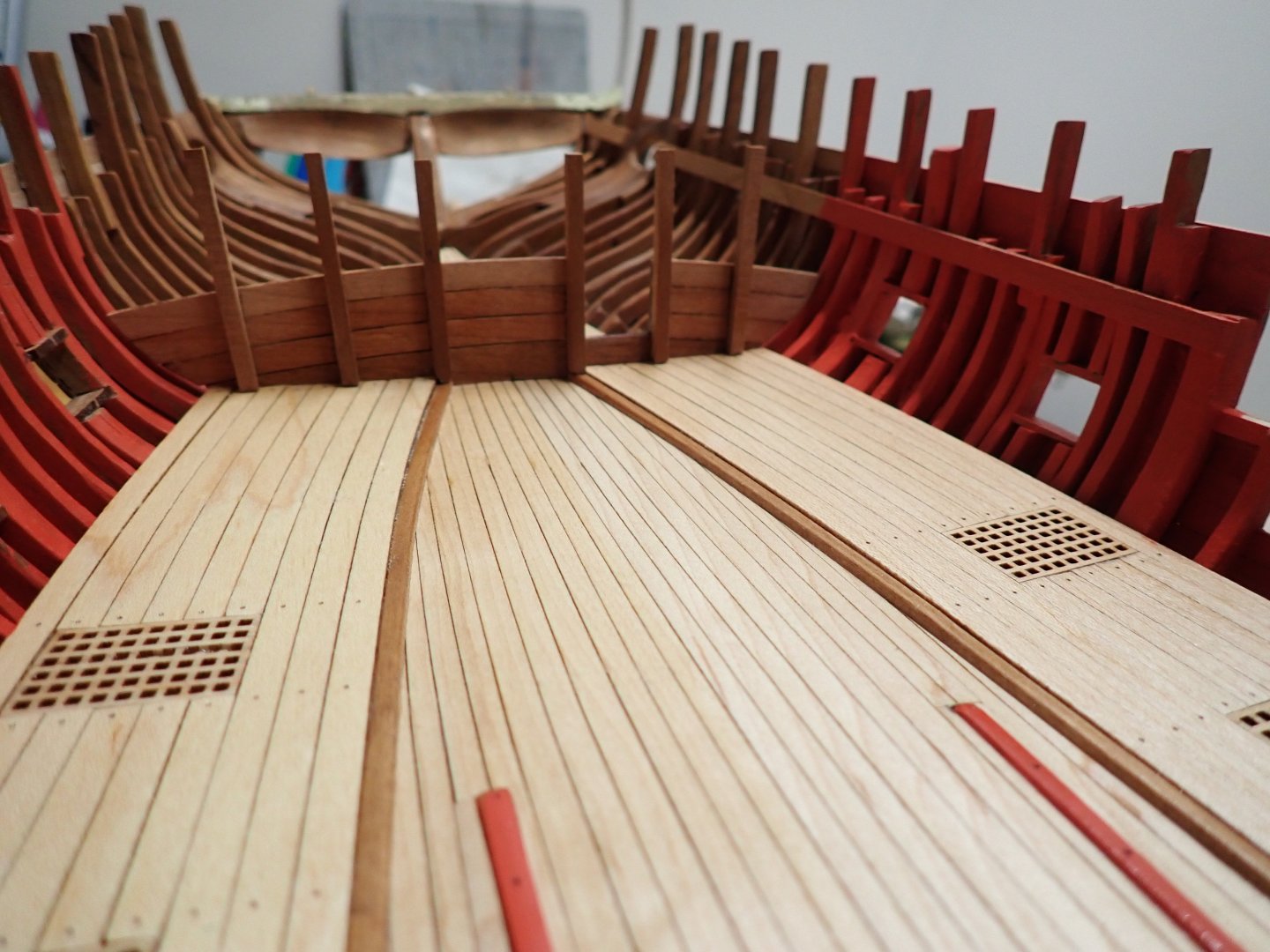
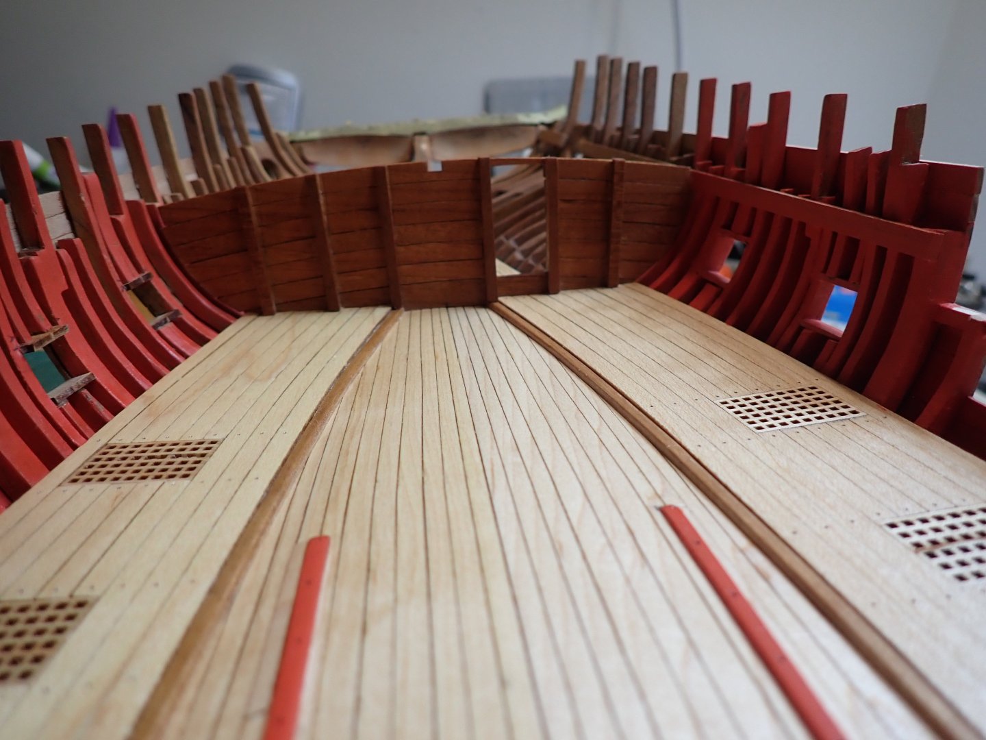
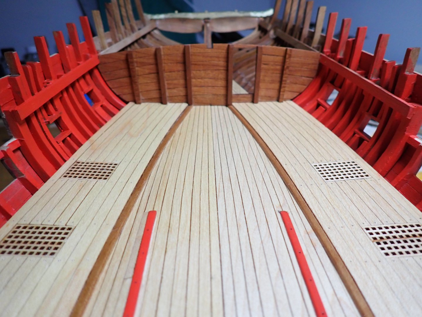
Moving along (slowly) with some delicate assembly. The kit calls for a 3x4 mm strips all along the handrail. Unfortunately, I do not have the exact molding profile and thus decided to go with a semi-round, instead. It goes in one piece from the stern to the tip of the railing. It will stay with the color of the wood for now. I may tone it down a little bit later.... Next is the assembly of the railing and the various strips going on the deck and bulkheads: Again, the kit calls for a dark strip of 4x4 mm which is enormous on that little deck. Instead I went with a strip of 2x3 mm matching the color of the deck: This provides a barrier when rolling the guns on the deck and potentially funnel the waters through the grates. I think its smaller size looks a lot better. Finally, that long piece of wood used to anchor the guns and attach various things can finally be installed at the right location and height: Now, to do the same on the other side.... Of course, all the parts (railings and strips) are painted before being assembled. Yves


- 185 replies
-
- 13
-
-

-
It is interesting to see how they implemented the building of the bow and stern, which is always difficult on this type of hull. Great poisoned gift that James gave you.... 🙂 Yves
-
Incredible work Kevin. Congratulations. You must be well "fatigued" after such a build 🙂 Are you going to resume the building of the big gun? Yves
- 443 replies
-
- 1
-
-
- Indefatigable
- Vanguard Models
- (and 1 more)
-
It is probably lacking some pipes to be your preferred subjects, Javelin ☺️ Yves
-
Yes, it looks like a real hull at this stage. Congratulations, this is going to be spectacular. Yves
-
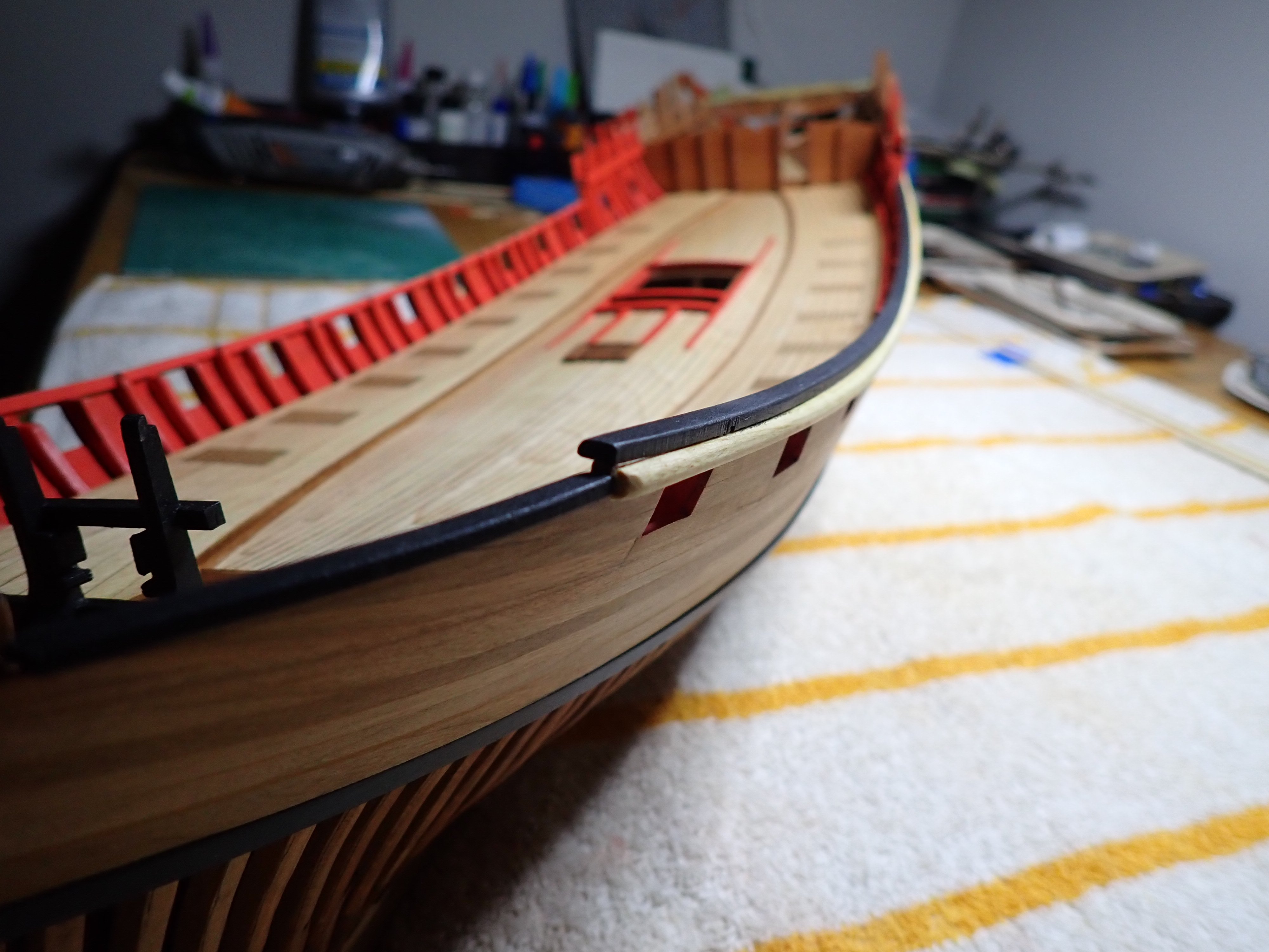
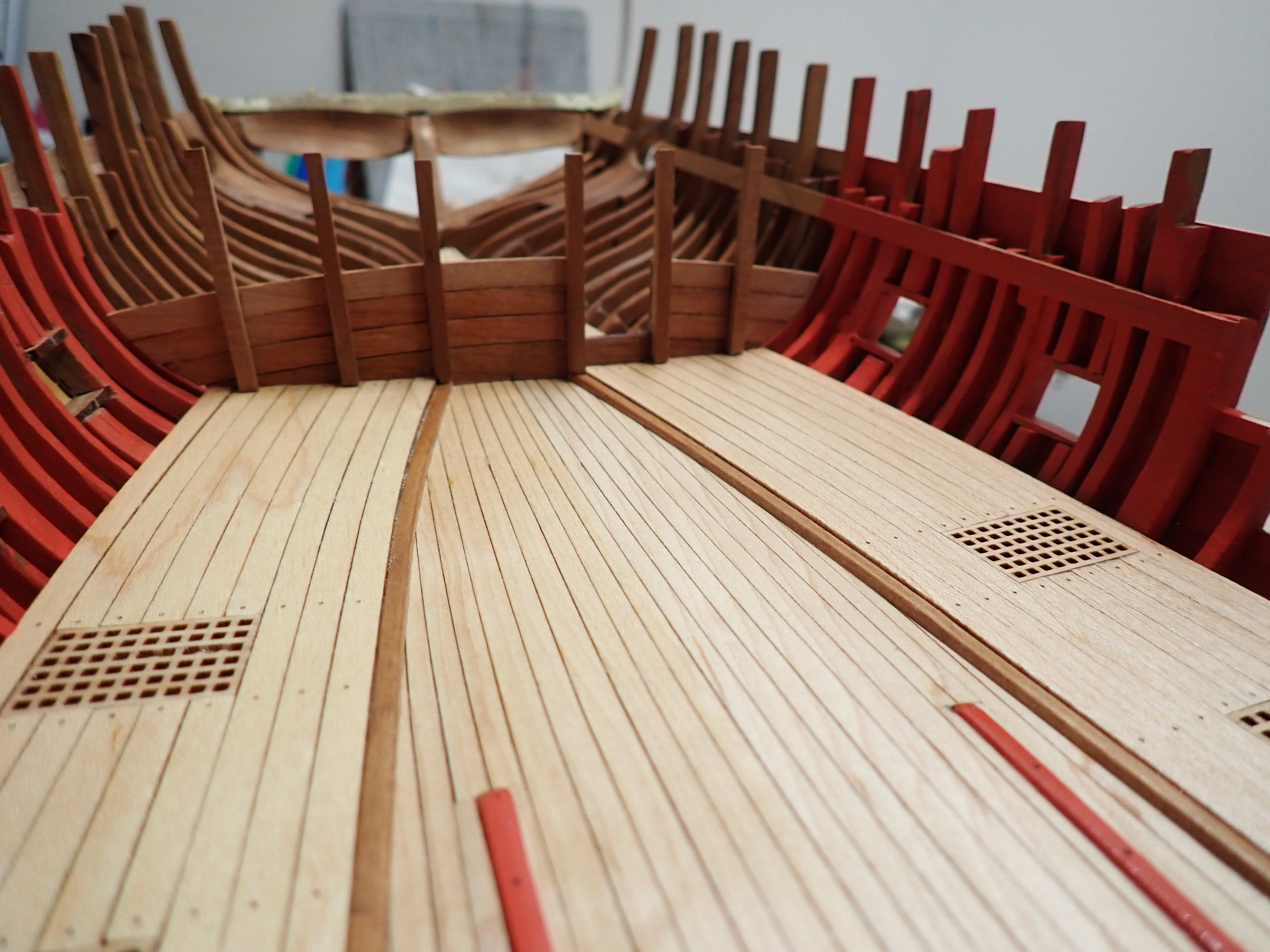
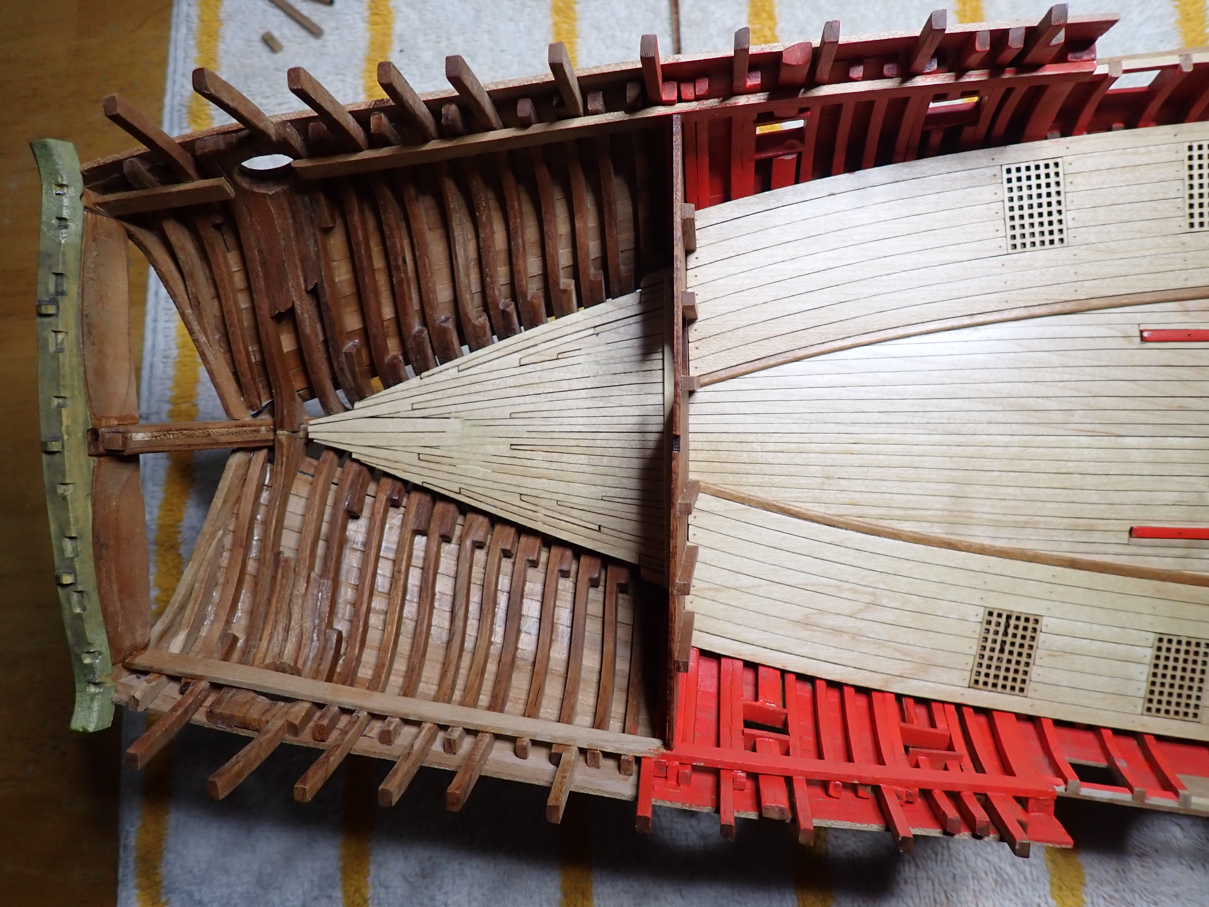
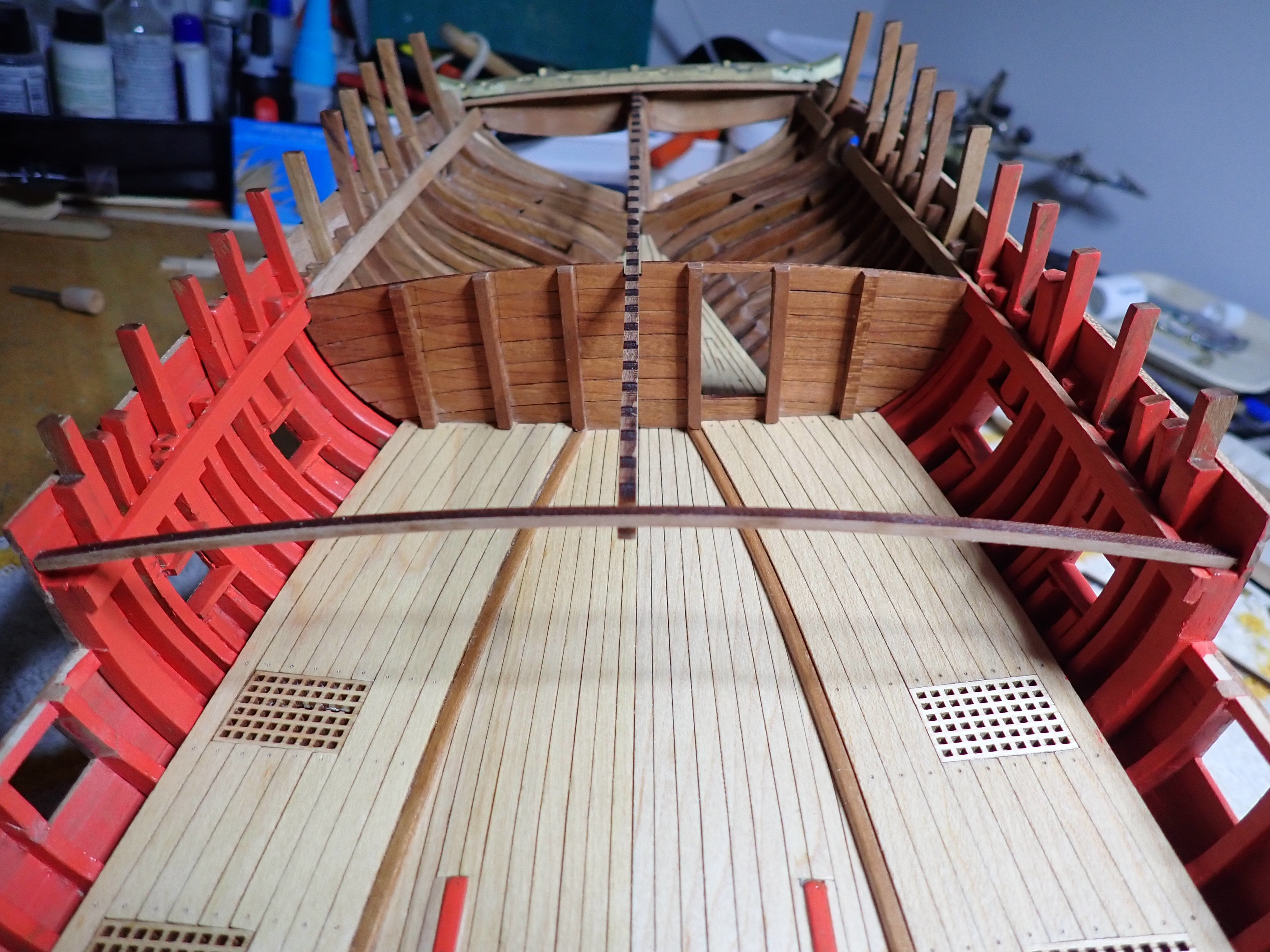
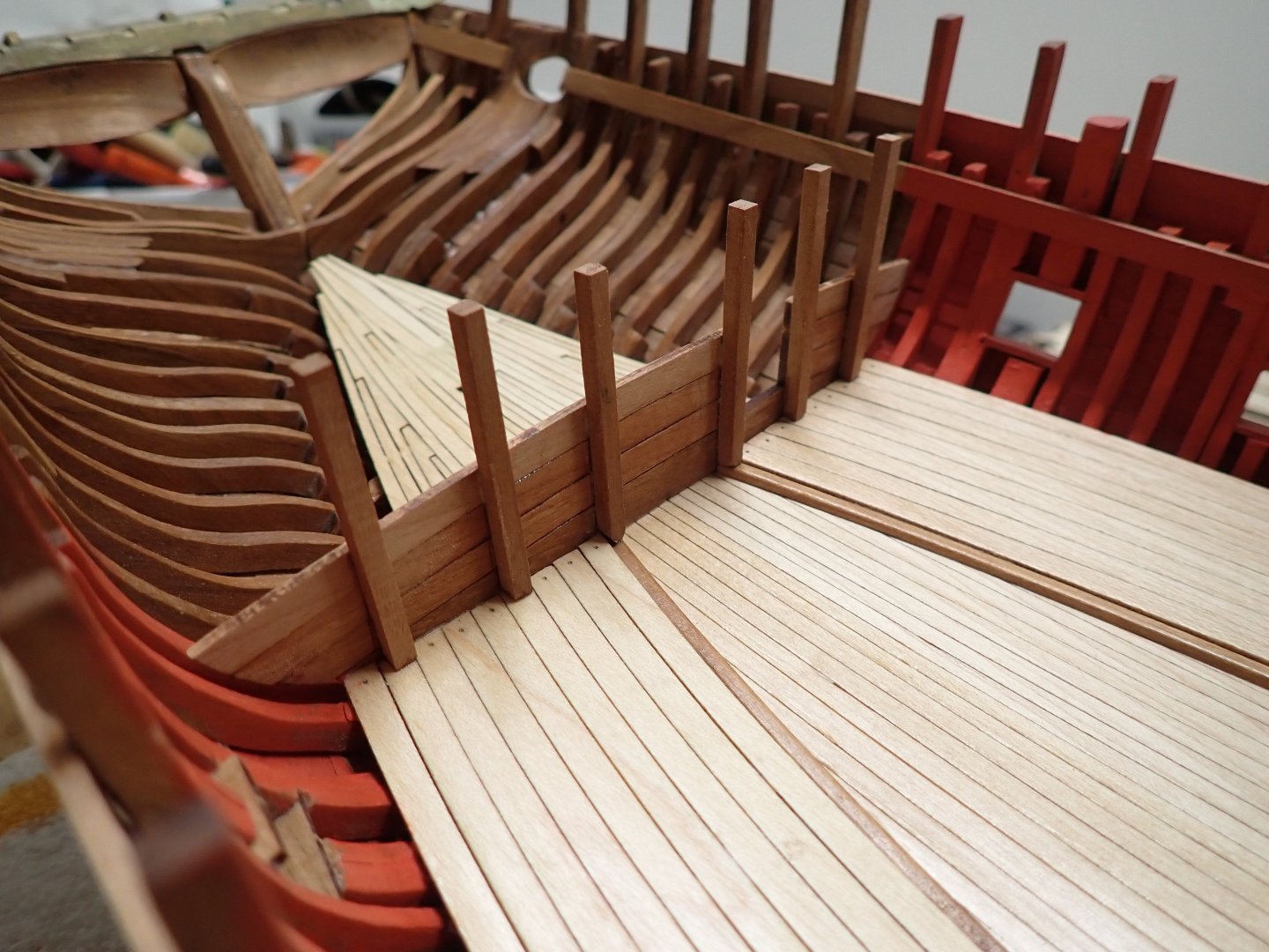
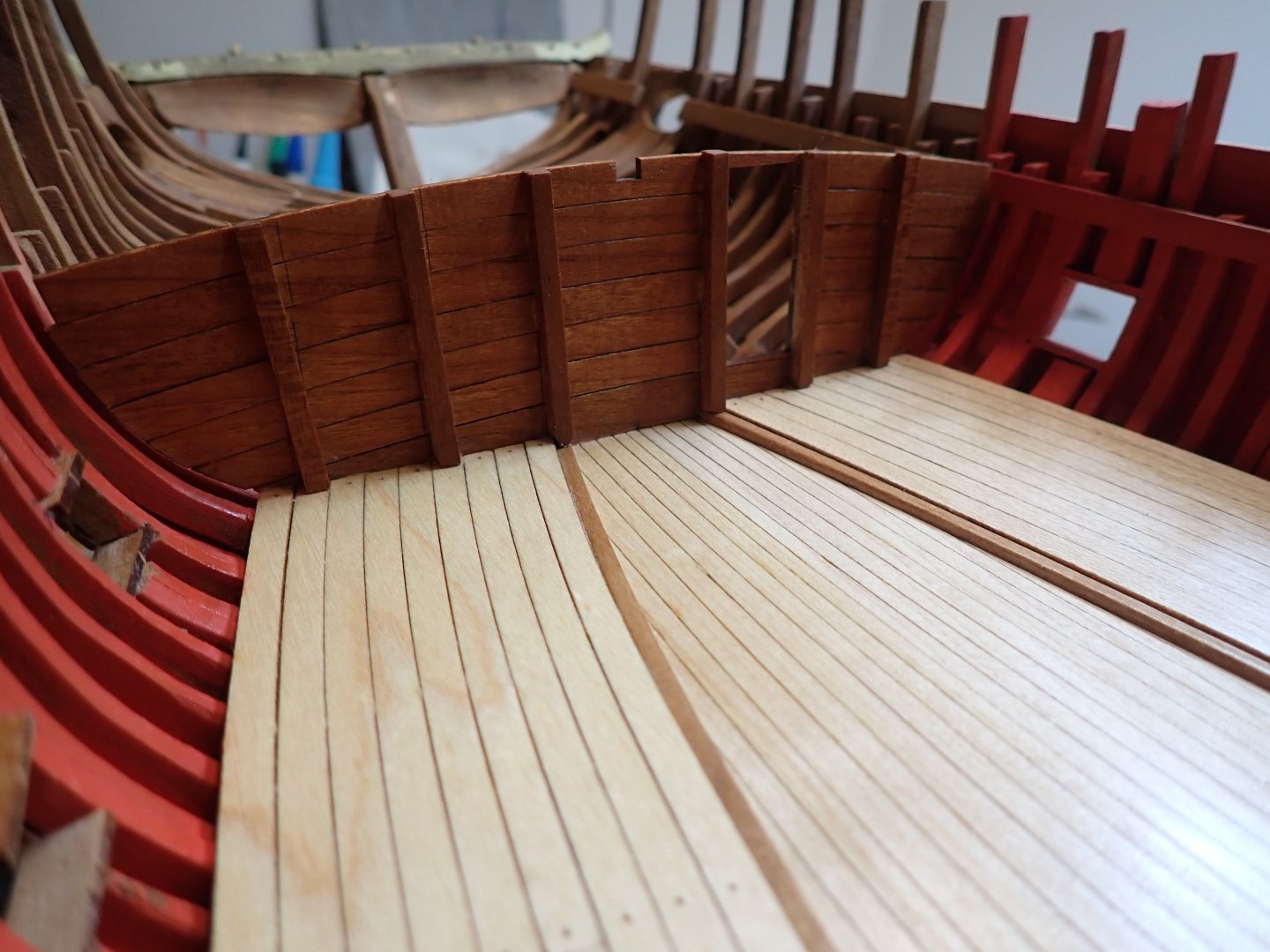
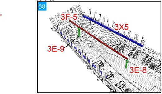
I am now concentrating on the stern as I need to make some progress there, to place the mizzen mast and the rear deck extension. Also, and not surprisingly, I am not following exactly the order of the instructions as suggested but moving along to what makes the most sense to me. Interestingly, the door is missing from the parts provided with the kit and as such, I will have to build it myself. It should not be too difficult. A few pictures of the construction of the cabin wall: It is now time to build the two large joists, which are supporting all the framing of the quarterdeck: After careful measurements, we come to this: I started assembling some of the quarterdeck framing, but nothing will be glued until I finish all the trims on the hull. It is way too fragile and will impede the correct installation of the guns and other details located on the main deck: Yves


- 185 replies
-
- 14
-
-
-
You are doing a very nice job with the planking of that hull. It is not an easy piece, for sure. Yves
-
Nice recovery Kevin. Yes, in a few months/years, it will all look the same. Yves
-
These brakes reminds me of the disc brakes used on the Citroen ID and DS and later on XM. Having the brakes next to the gearbox, reduced the UN-suspended weight and allowed for massive stopping power. Yves
-
She is a beaut, Clark !!! Yves
-
Interesting and unusual kit. I will be following with interest your model. Yves
- 23 replies
-
- 4
-
-
- Speedwell
- battle station
- (and 1 more)
-
Kevin, This rigging looks amazing. Man, you are patient and precise in your work. Yves
- 443 replies
-
- 3
-
-
- Indefatigable
- Vanguard Models
- (and 1 more)
-
I am so glad you could donate your model to a Museum. This way, many people of all ages and backgrounds will be able to admire this superb model. Yves
- 32 replies
-
- 2
-
-
- St Louis
- 3D Printing
- (and 2 more)
-
You did a fantastic job on the gold ornaments. Yves
-
Please take some pictures from the show (if your hands are not too busy with kits and parts). Yves
-
That is a good feeling. I love it when I am discarding empty sprues or laser cut wooden plates, devoid of any parts. It means two things: 1) You are making great progress and 2) It is time to think about your next project. Yves
-
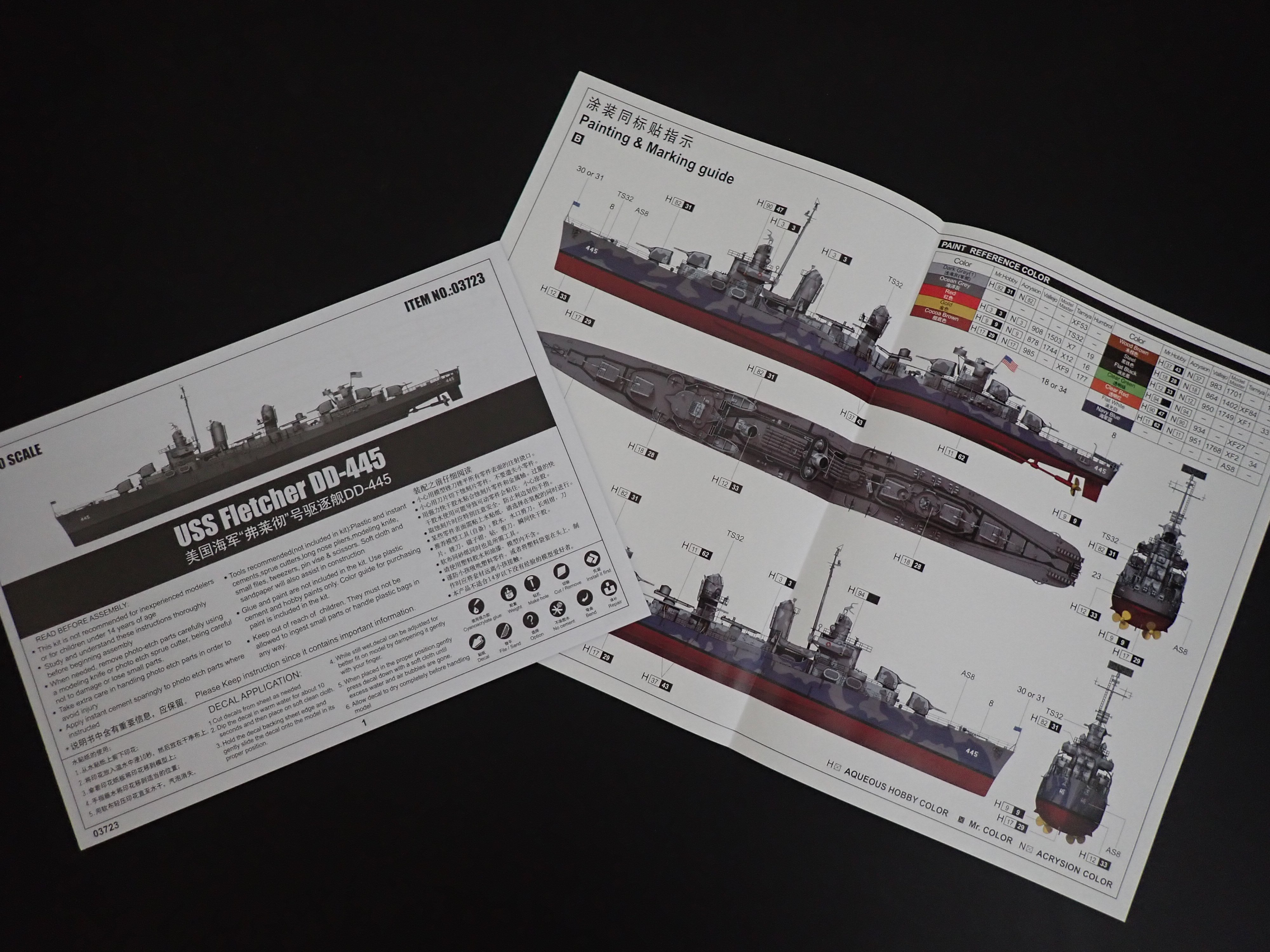
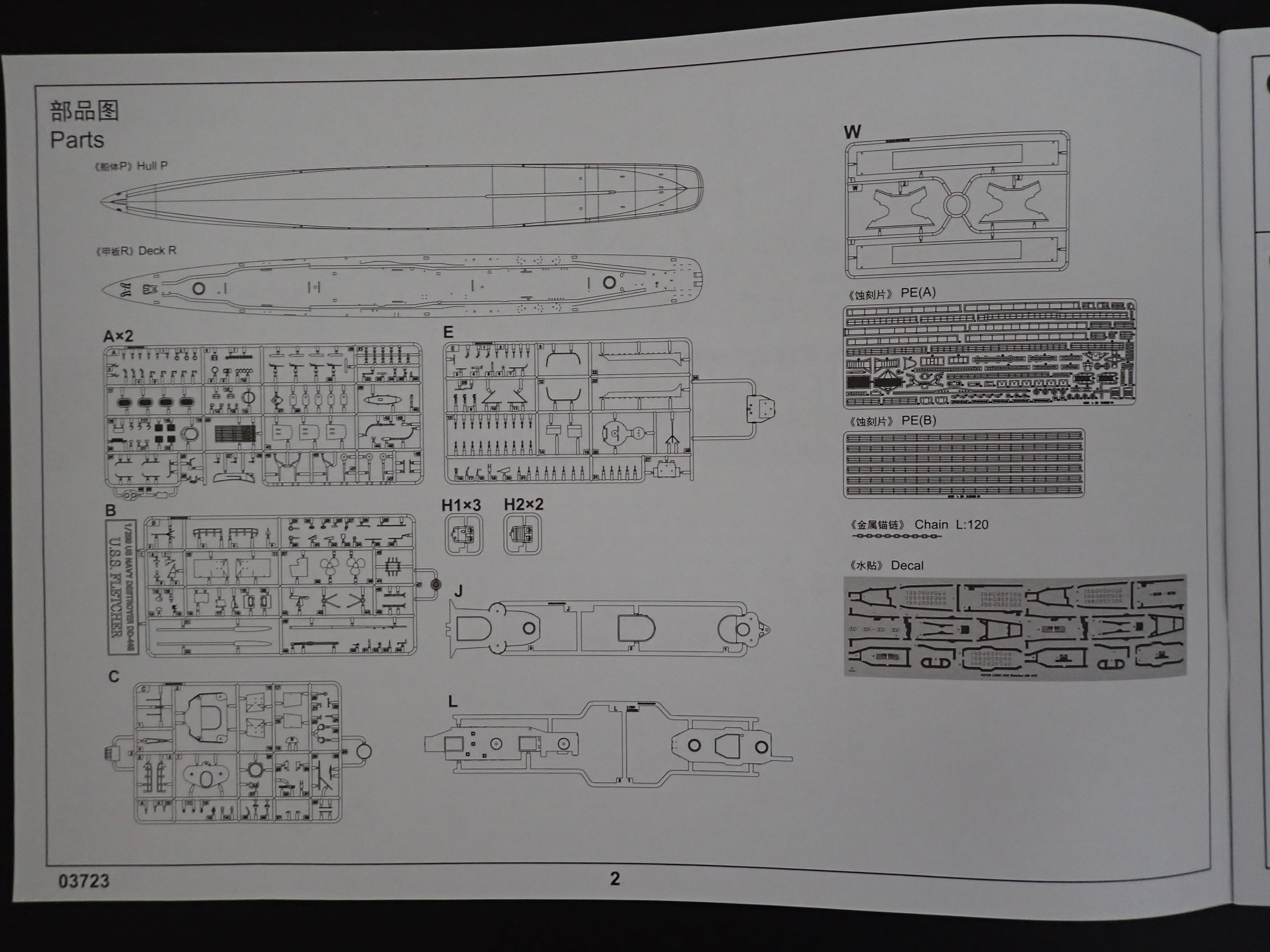
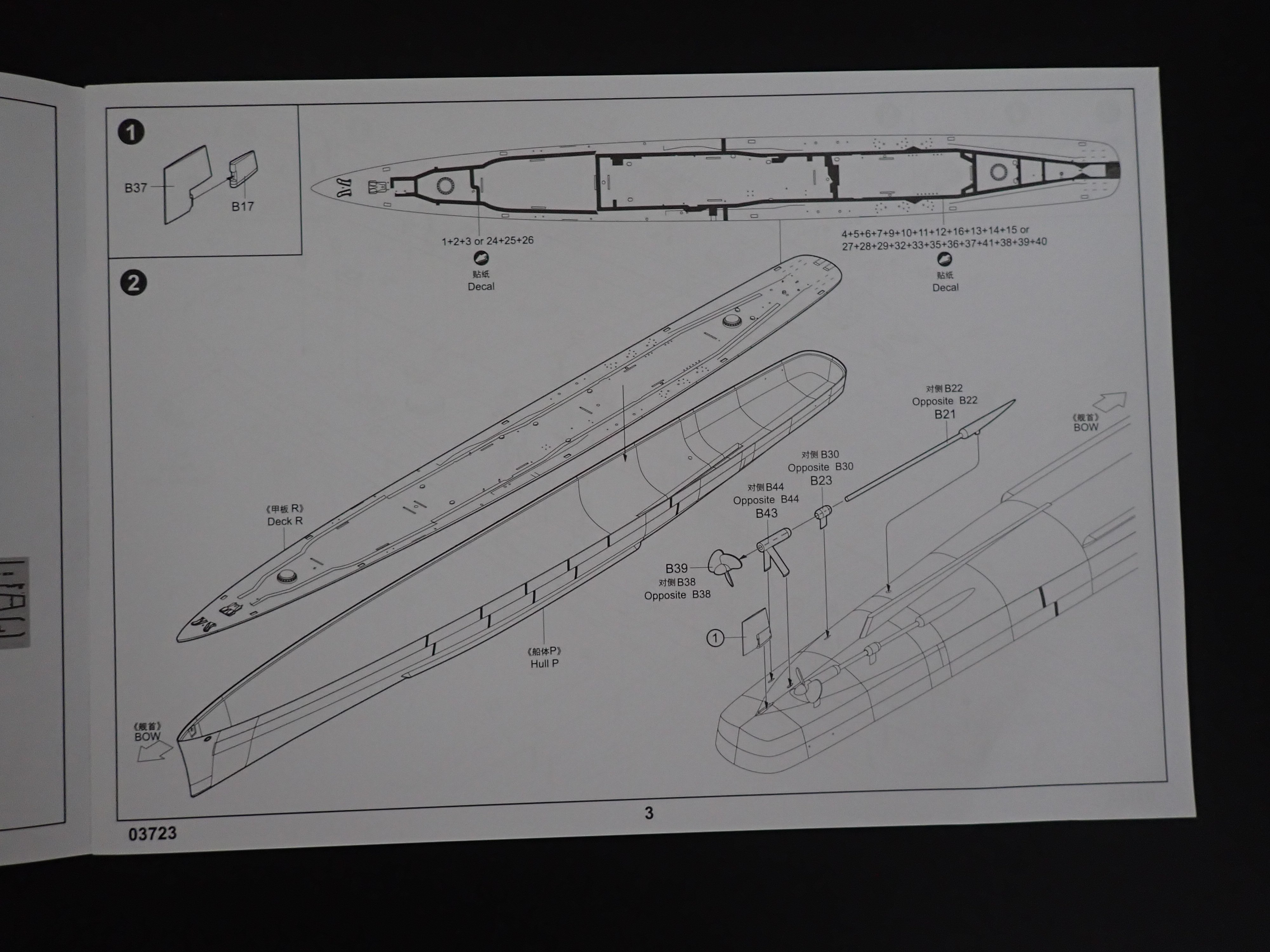
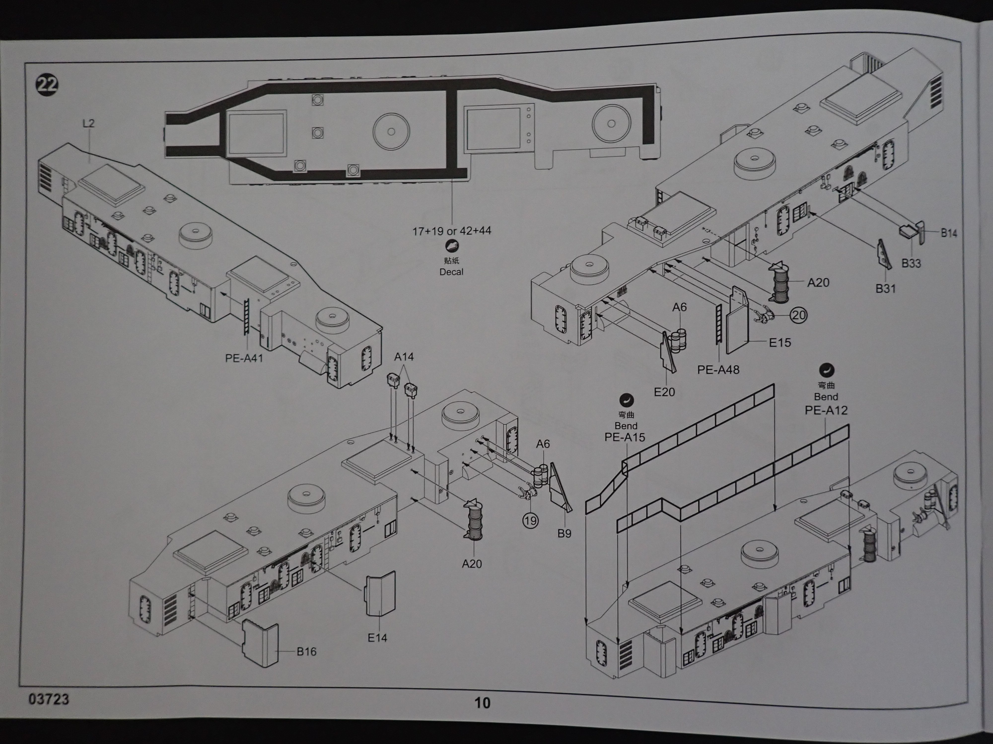
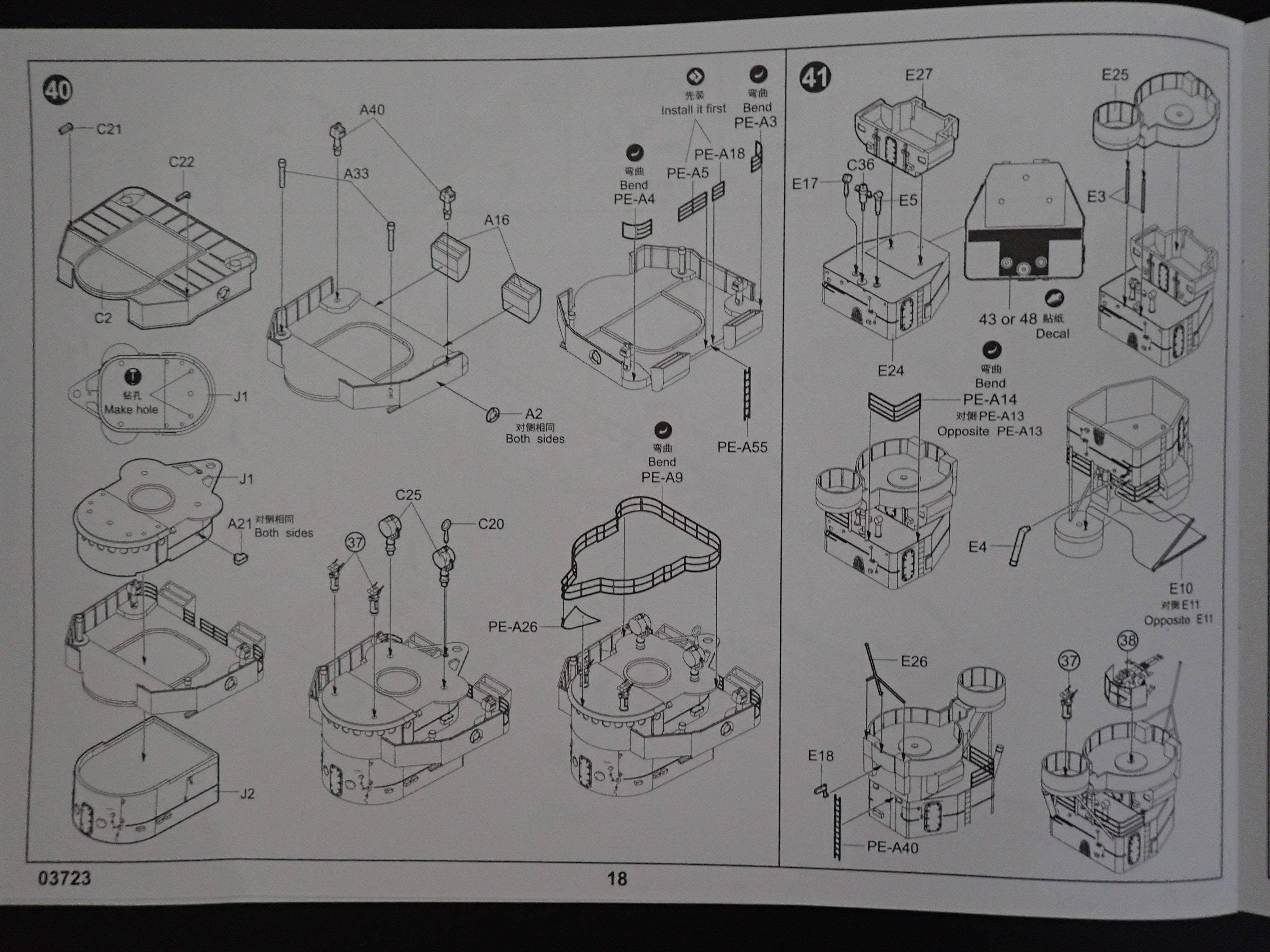
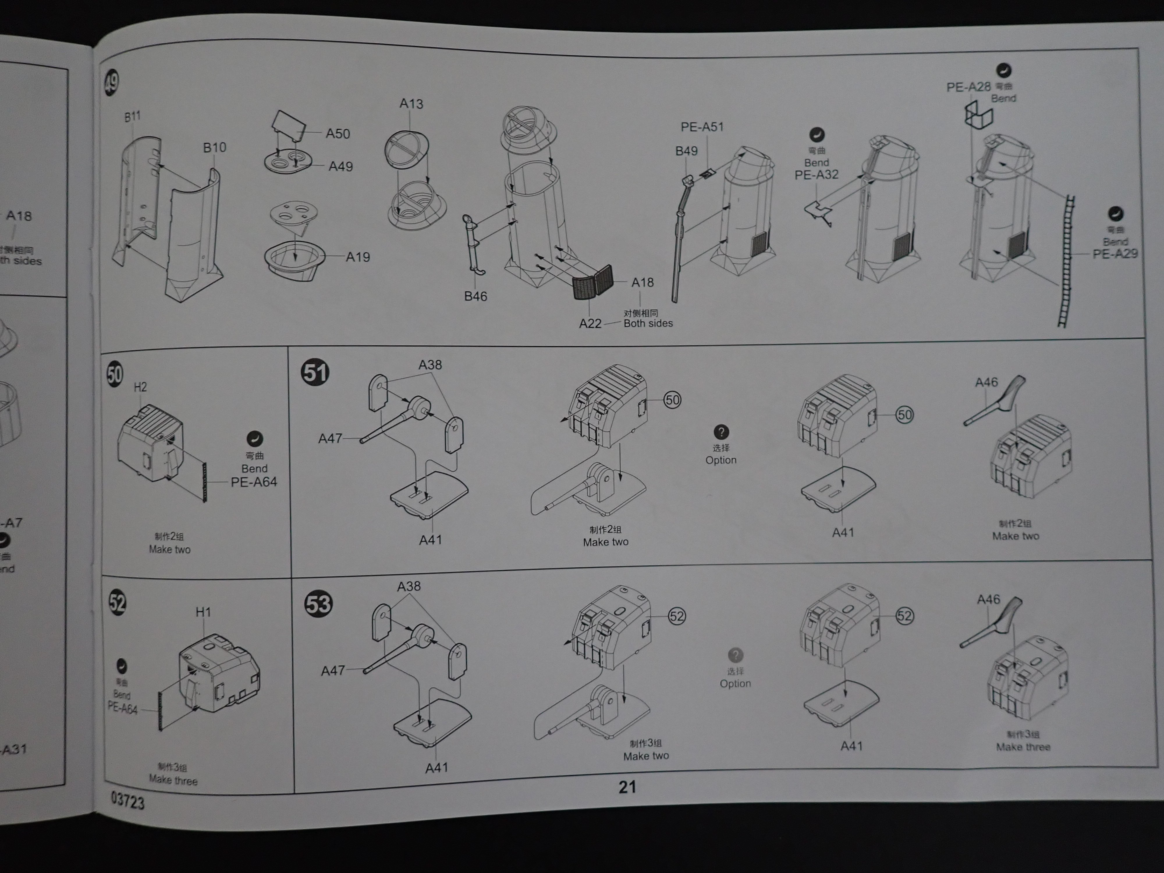
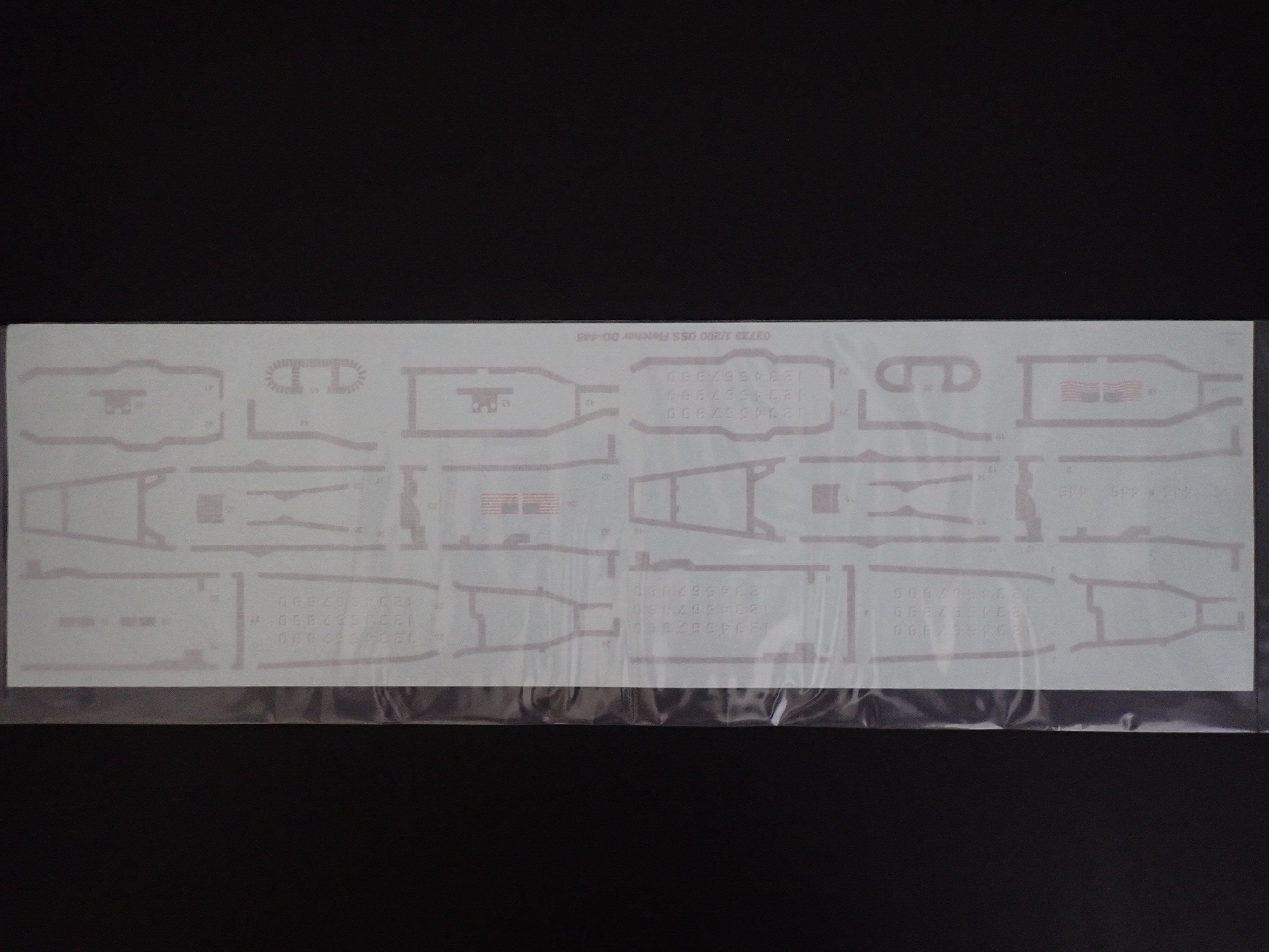
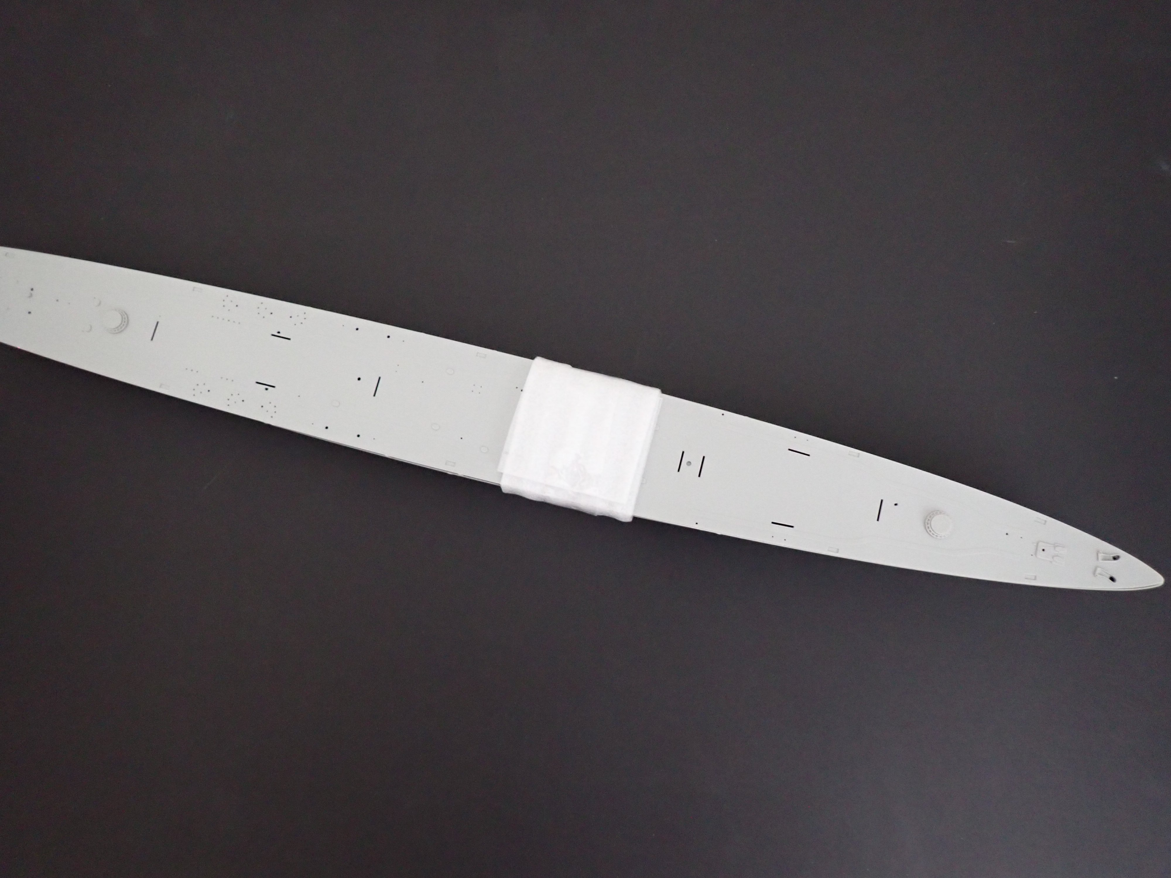
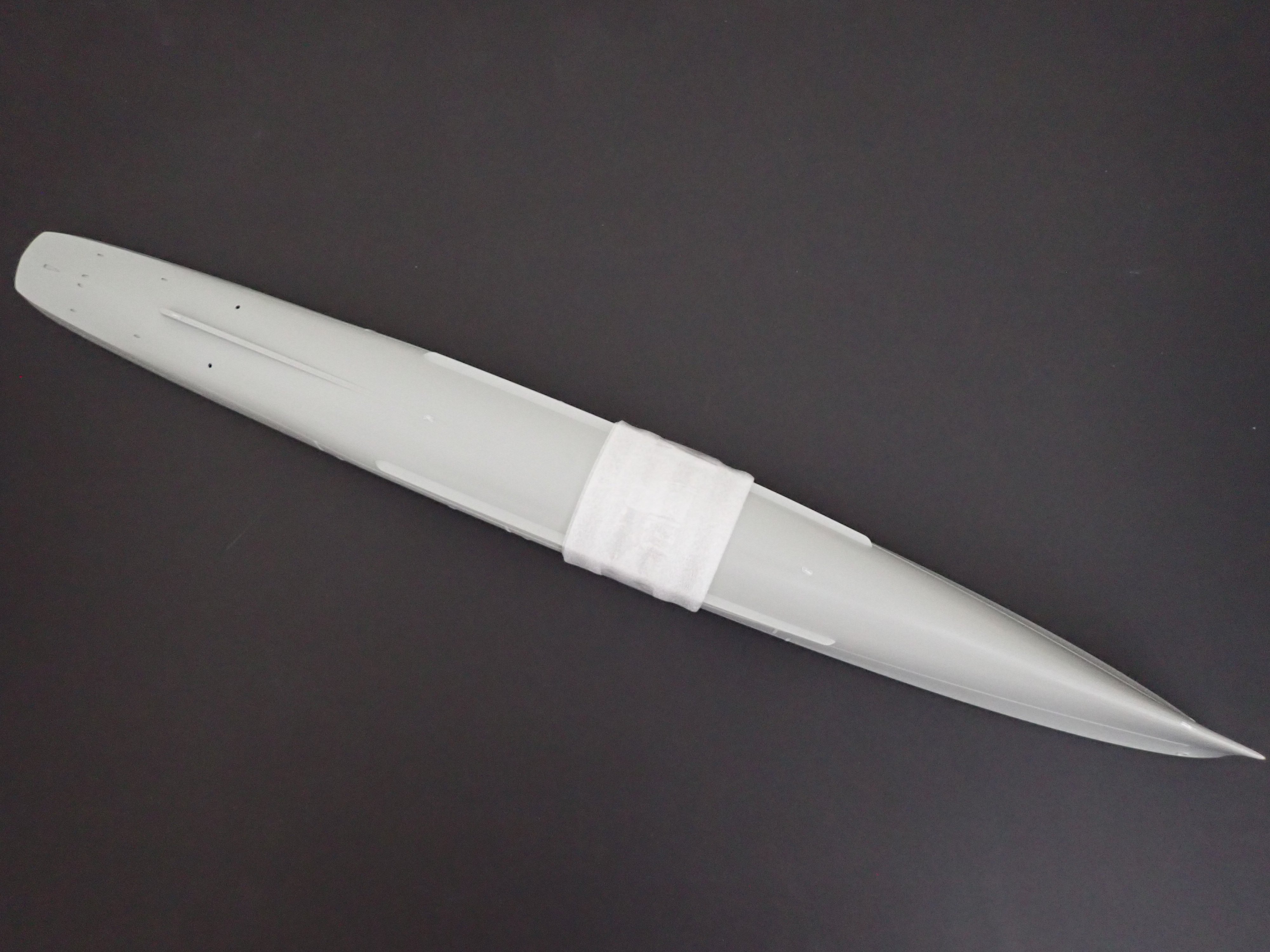
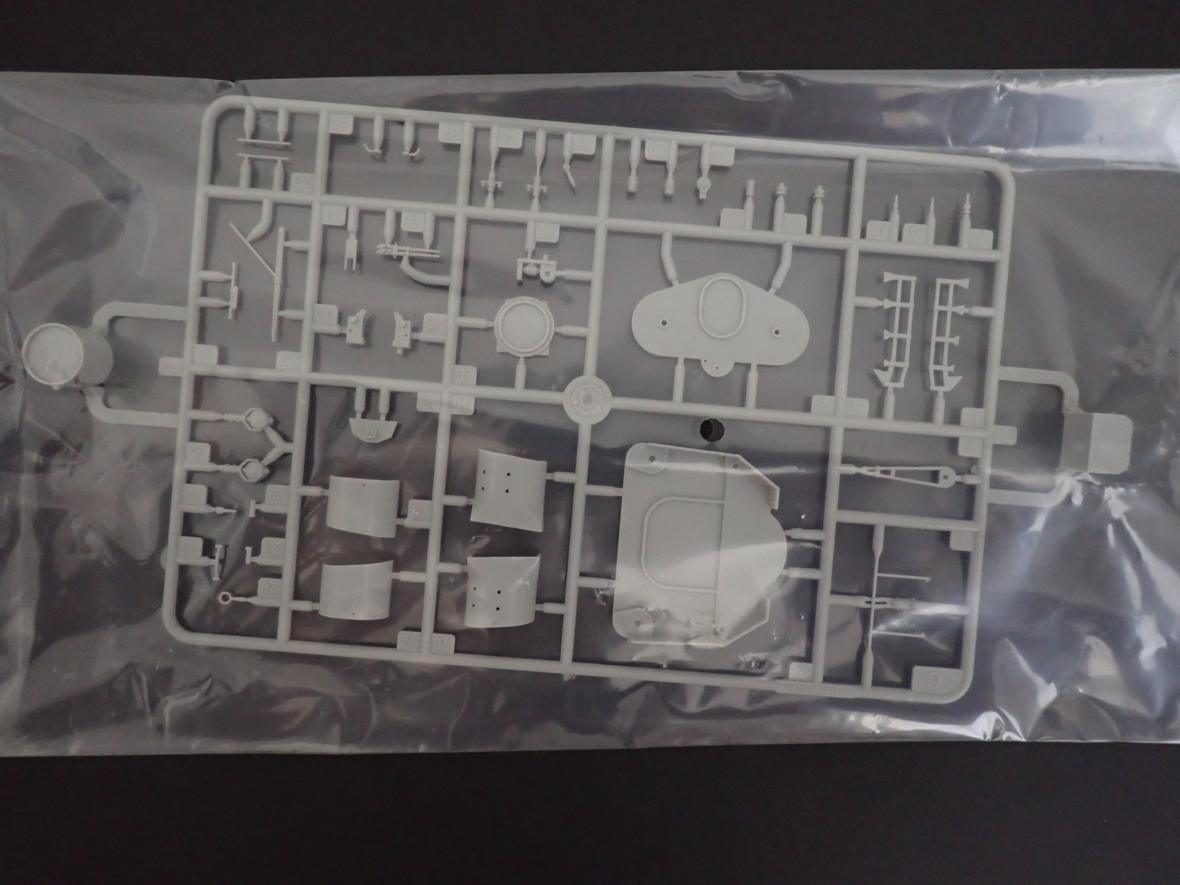
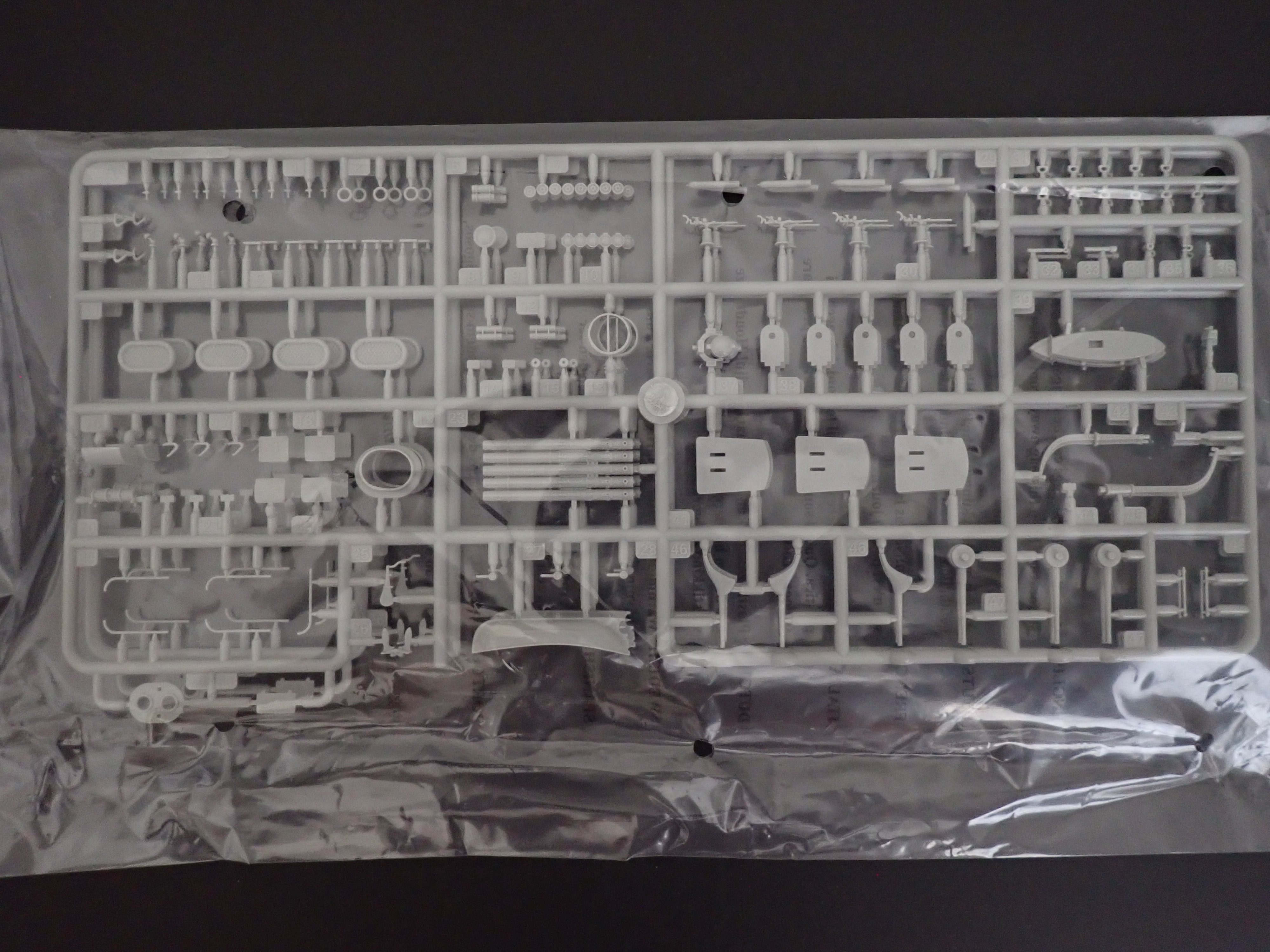
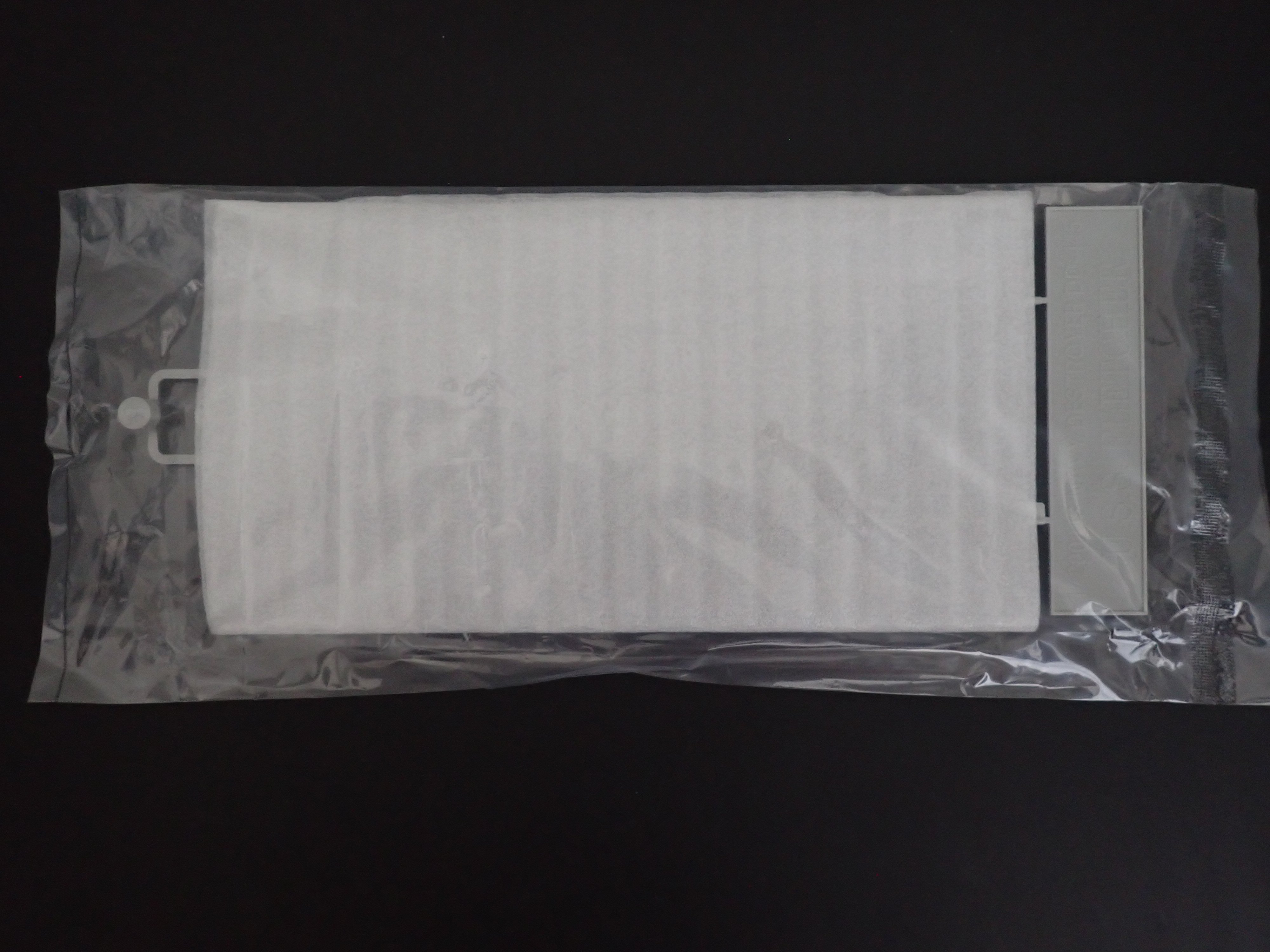
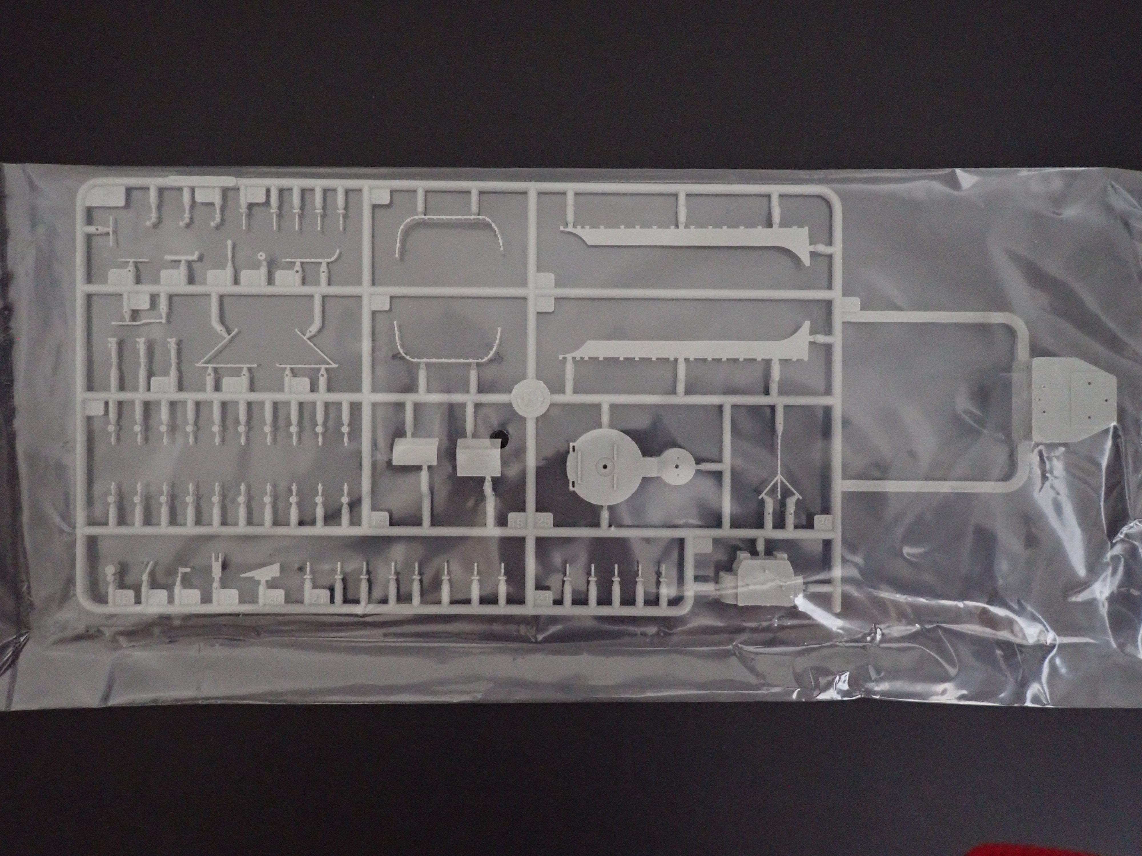
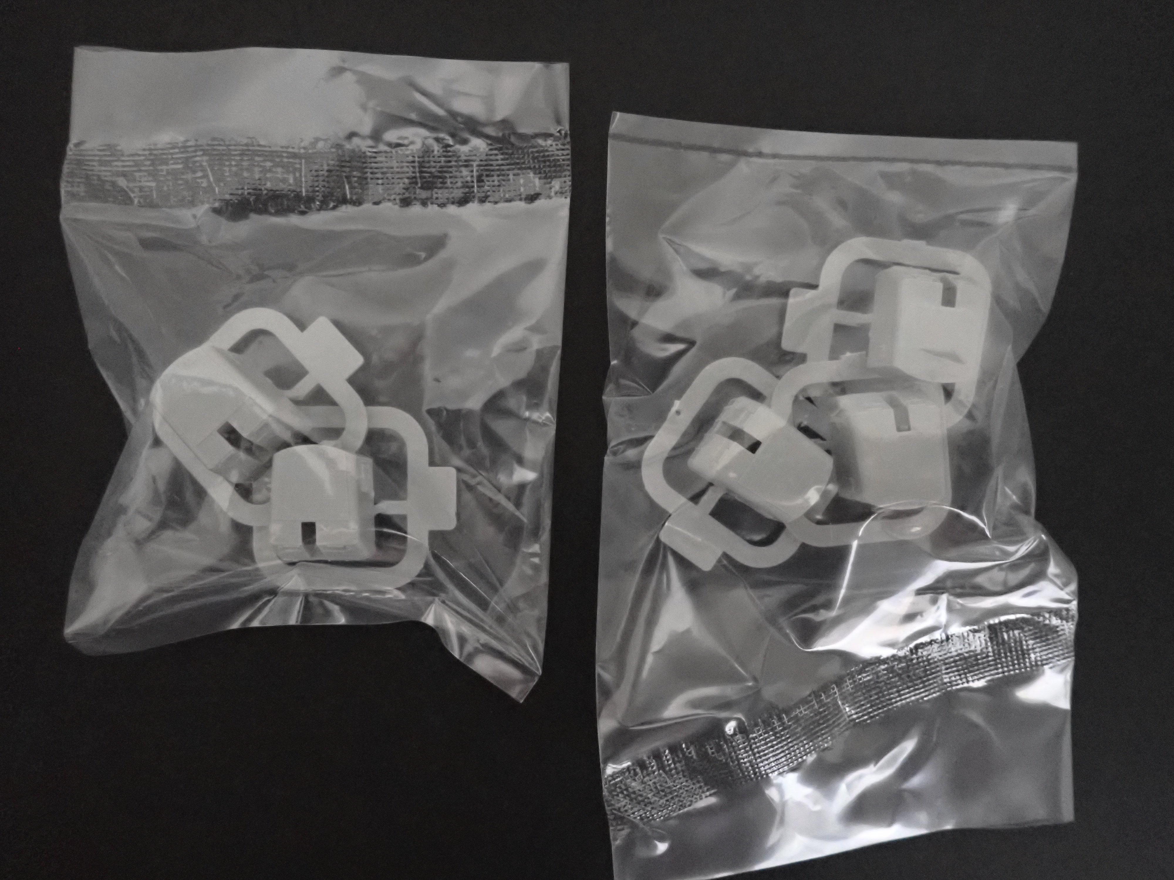
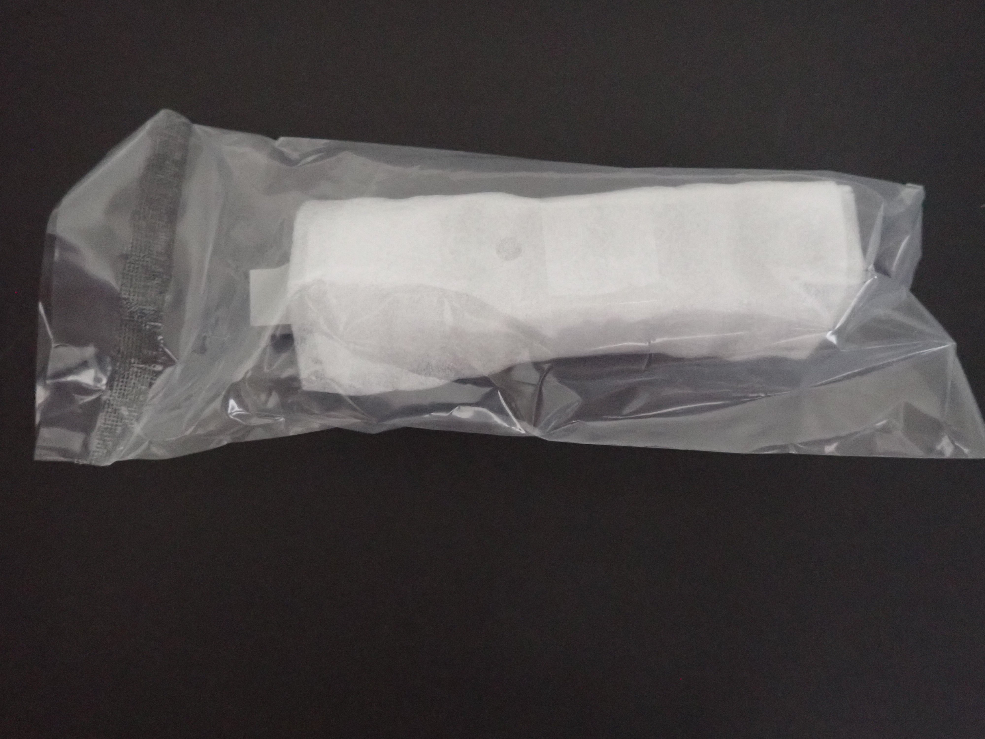
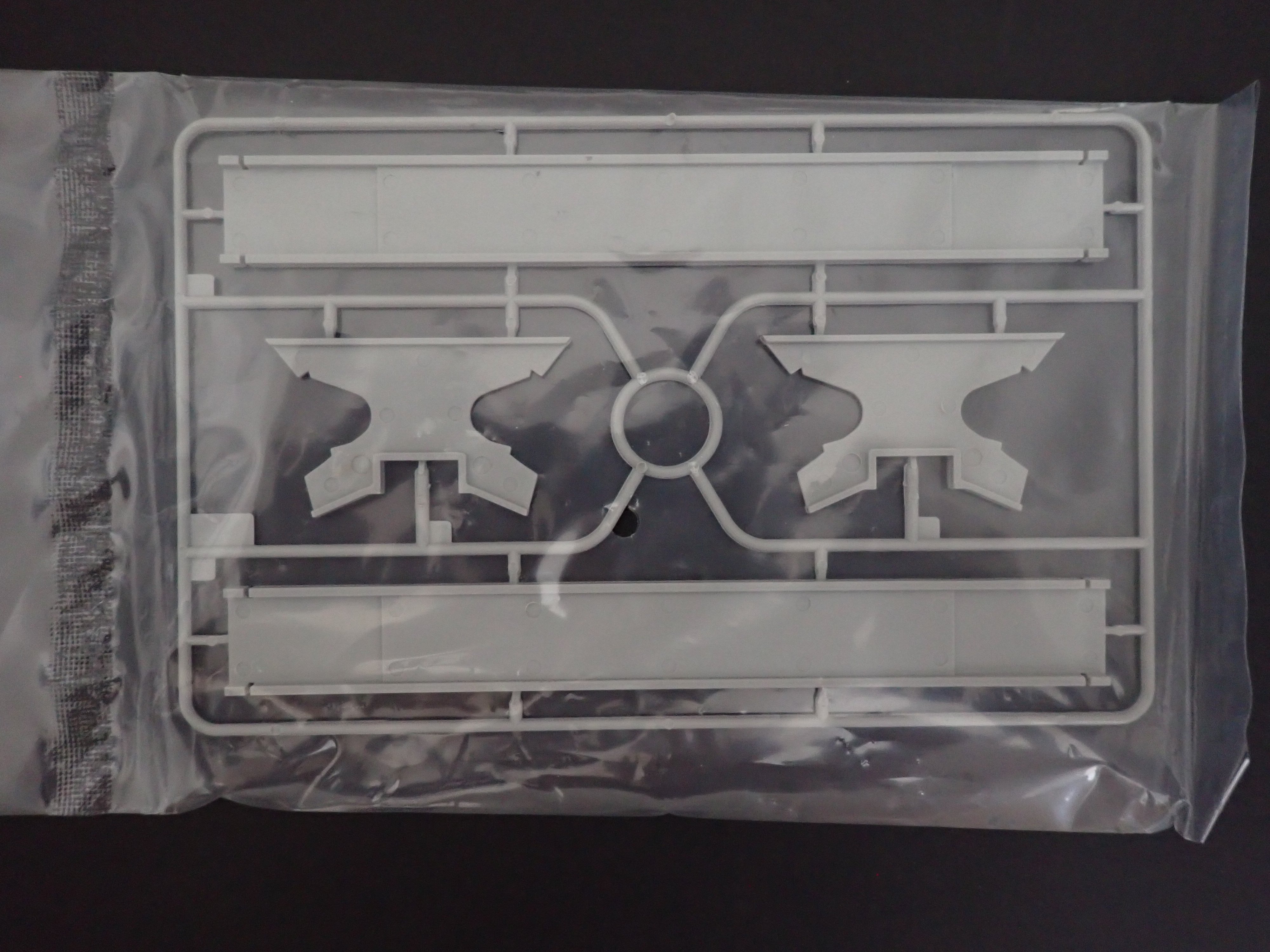
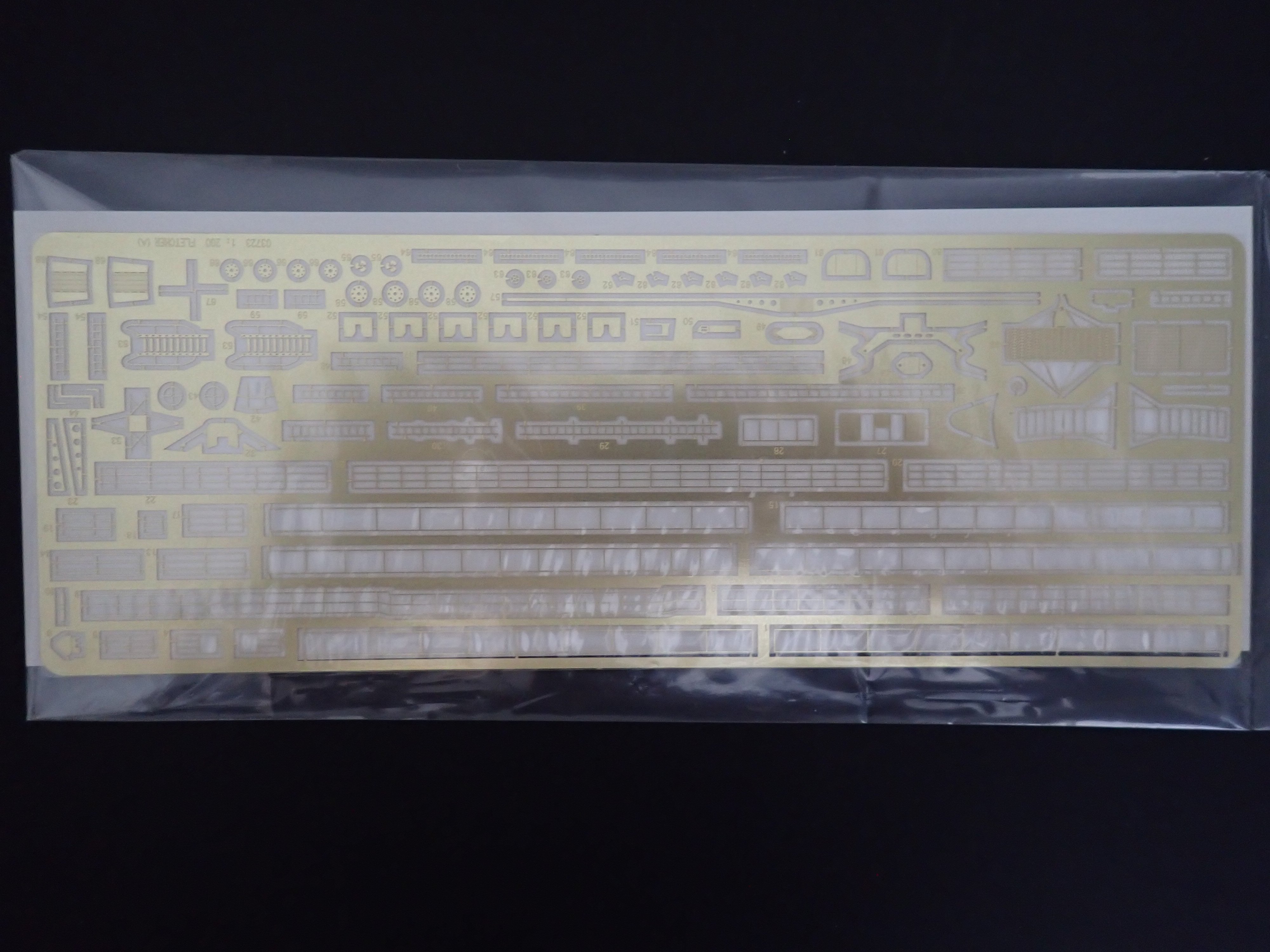
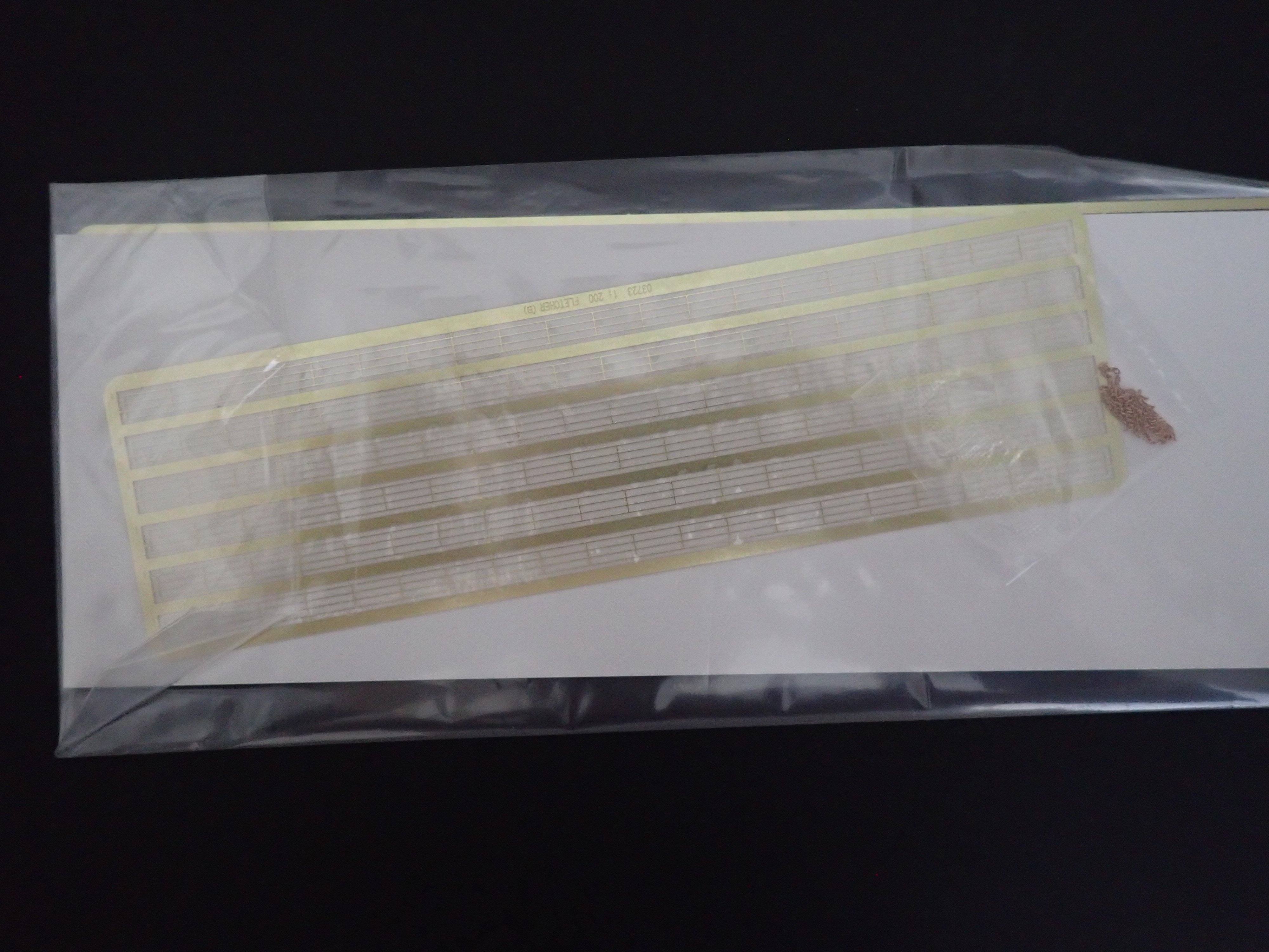
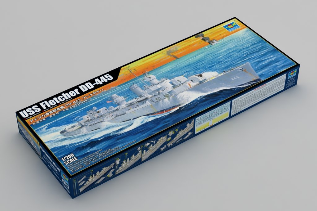
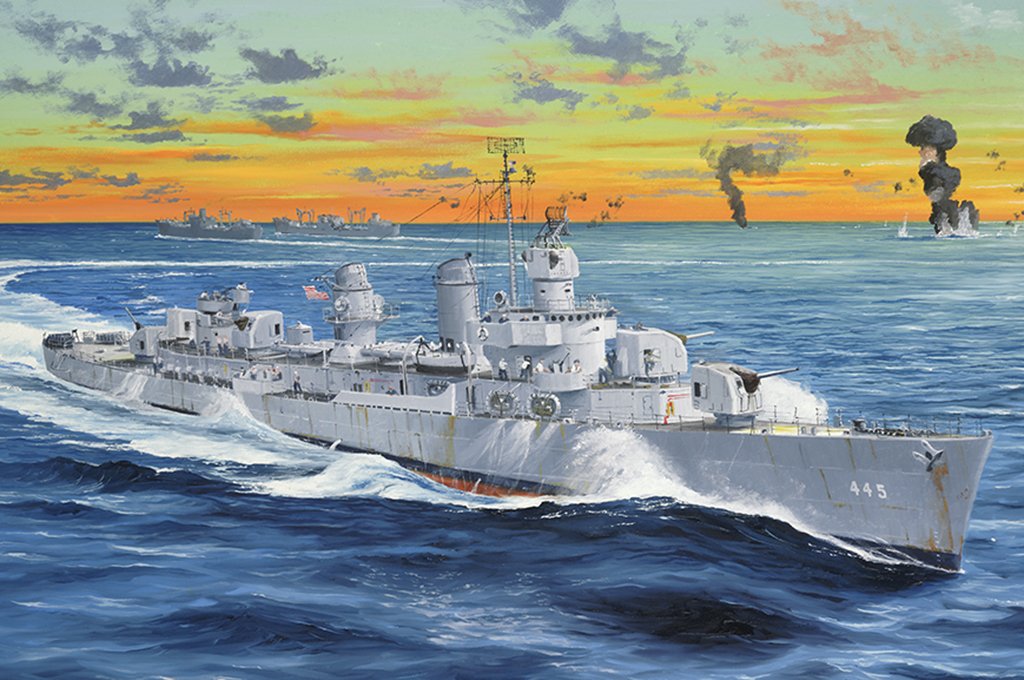
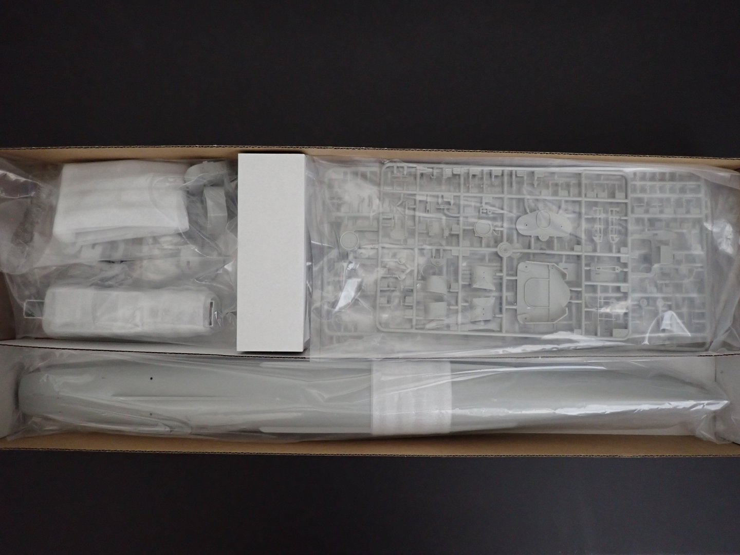
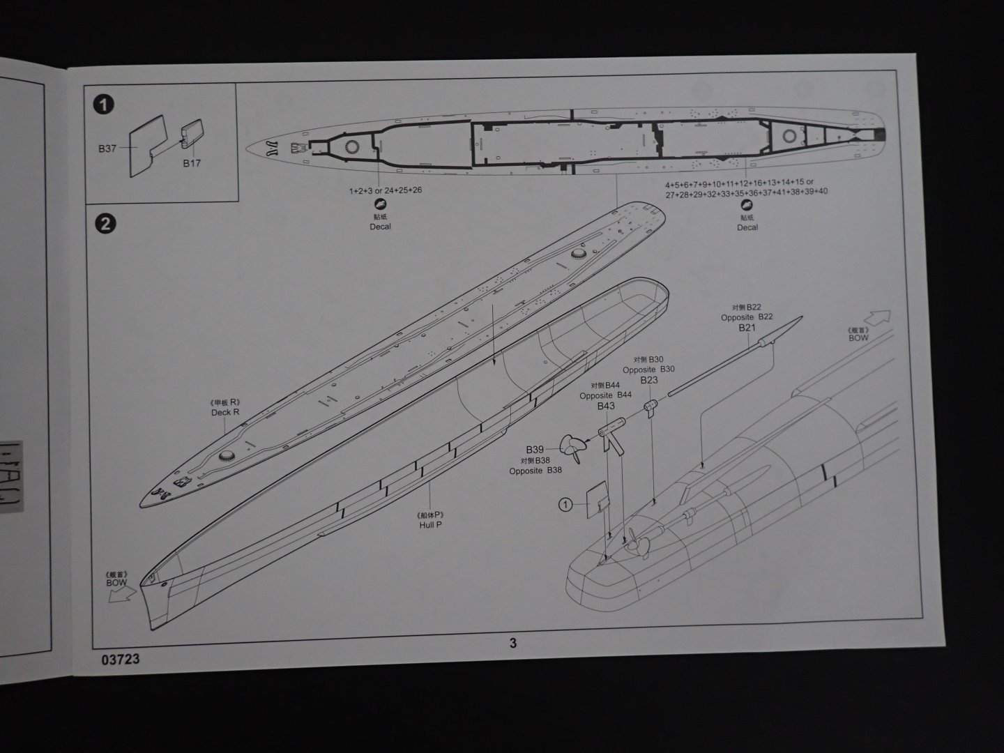
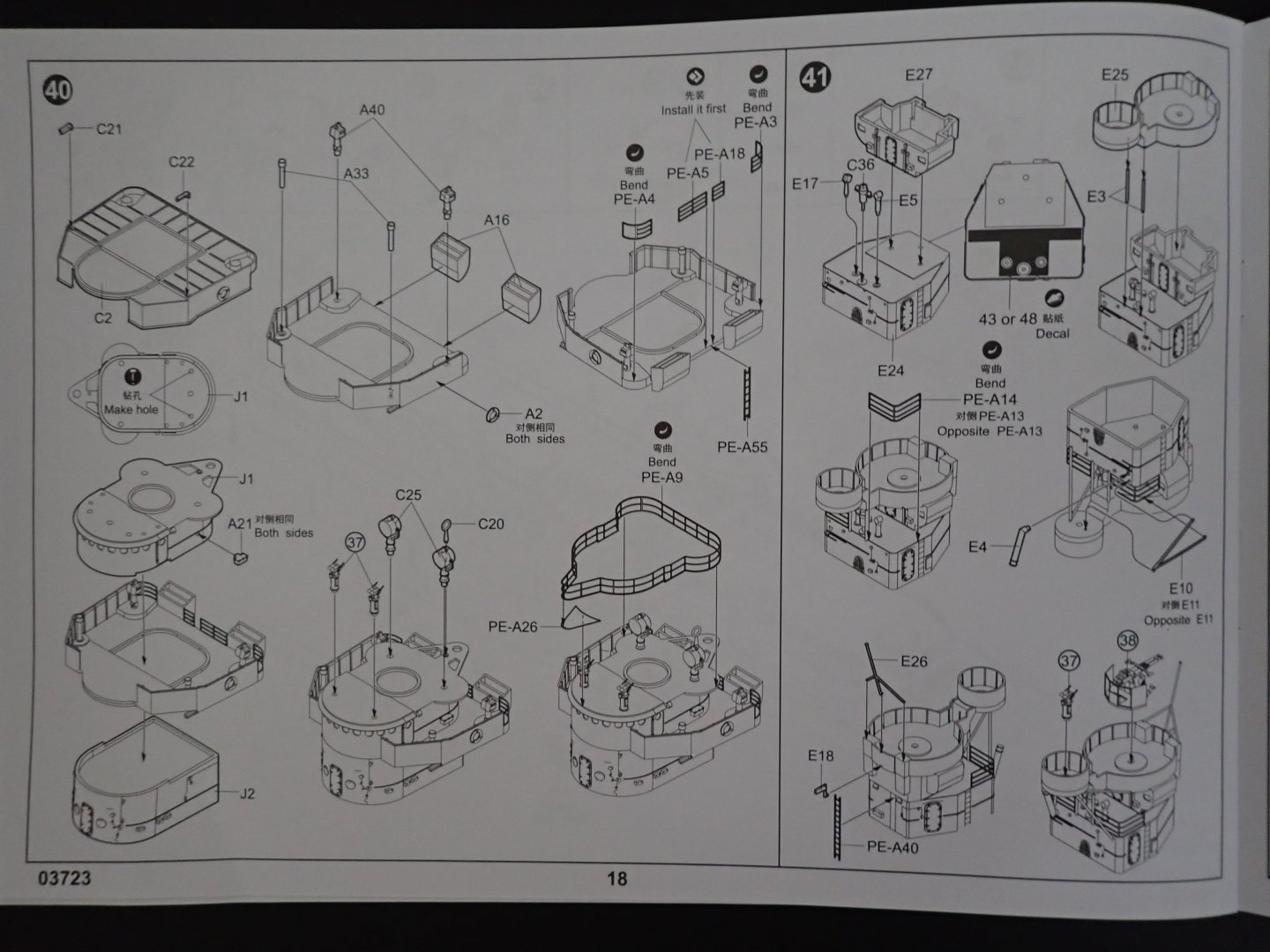
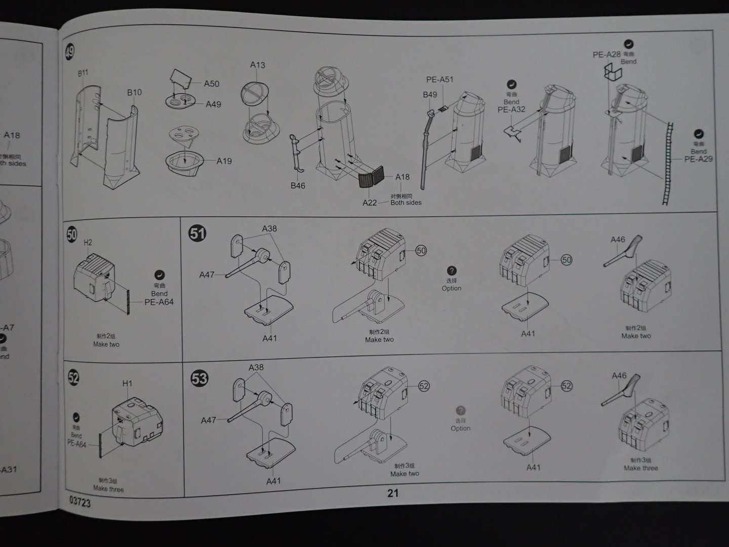
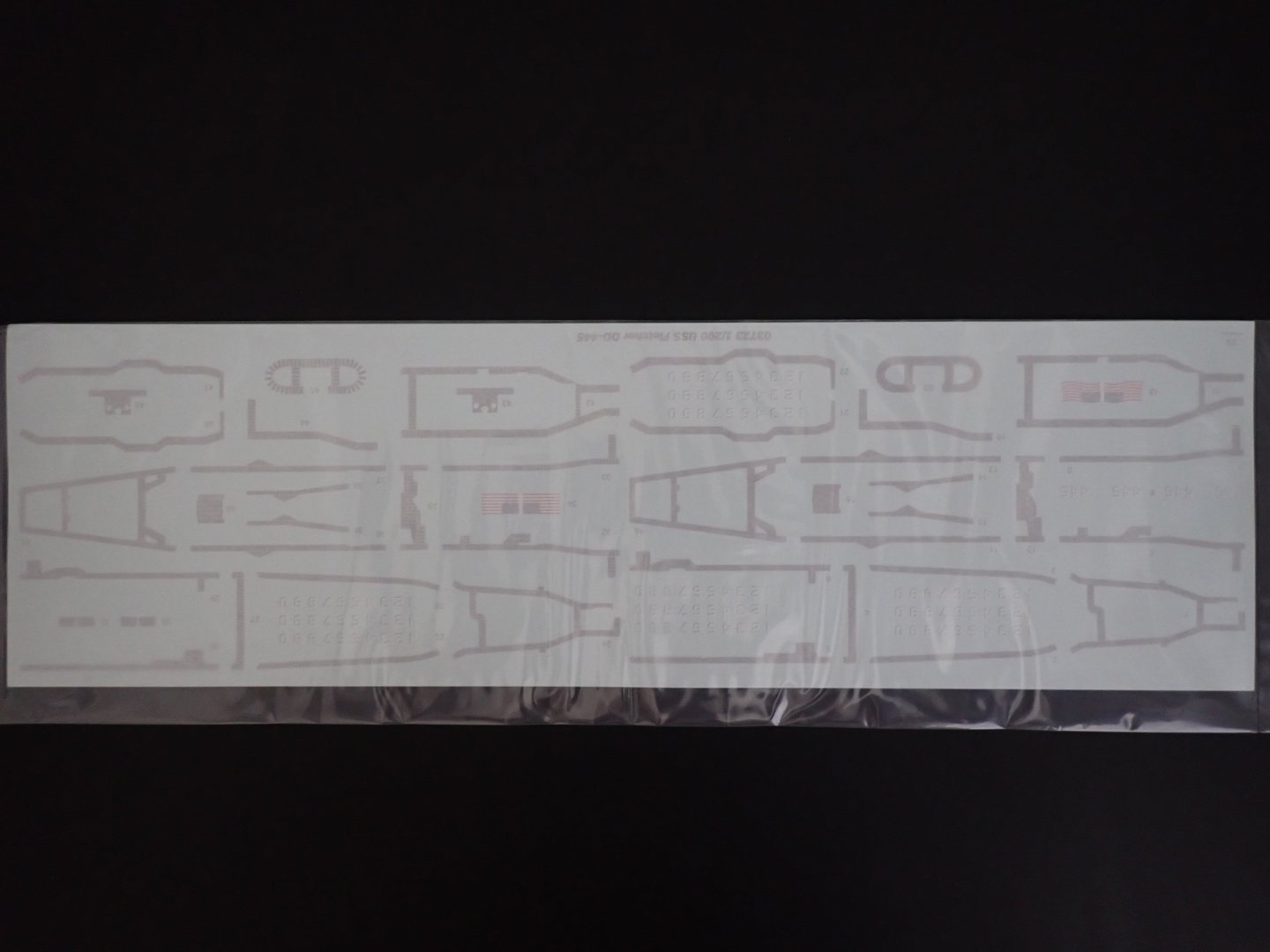
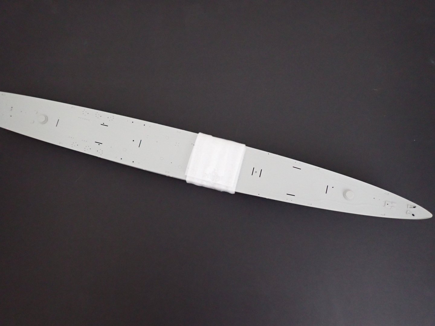
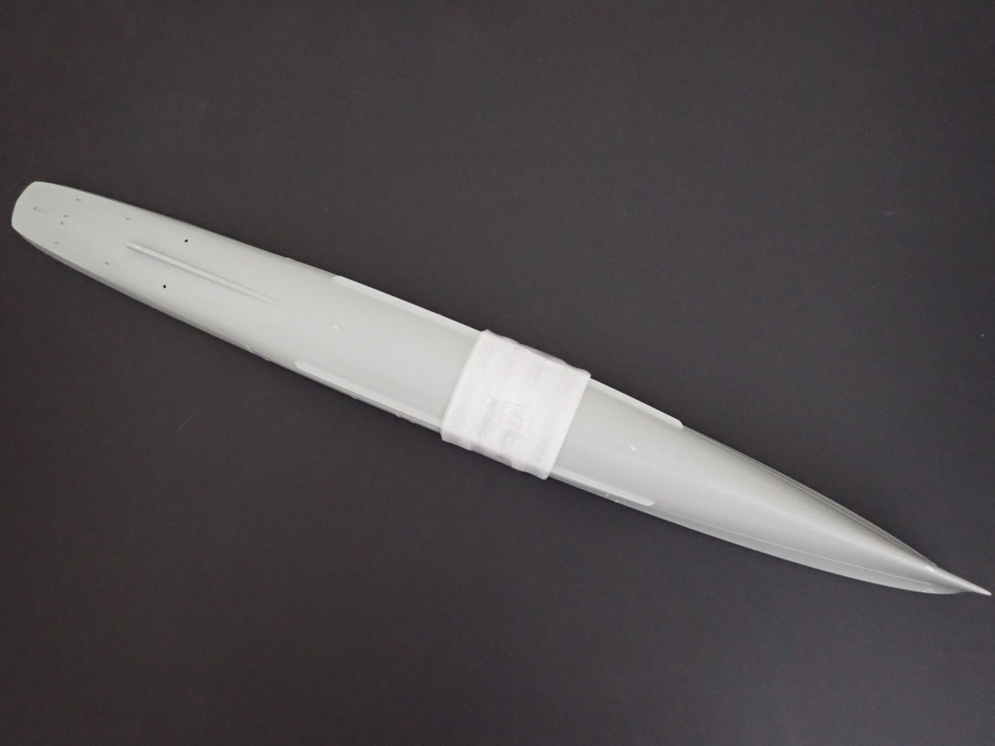
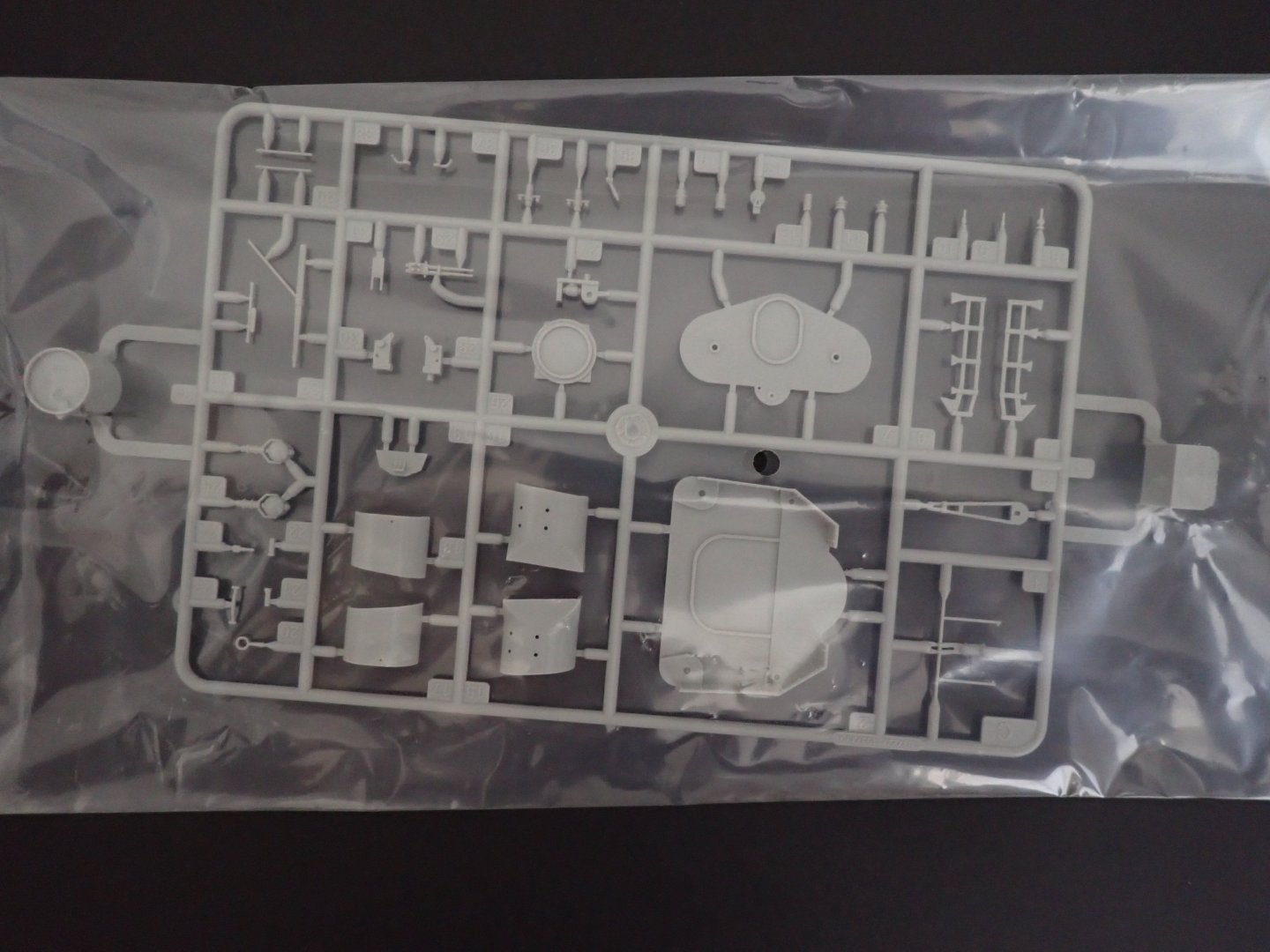
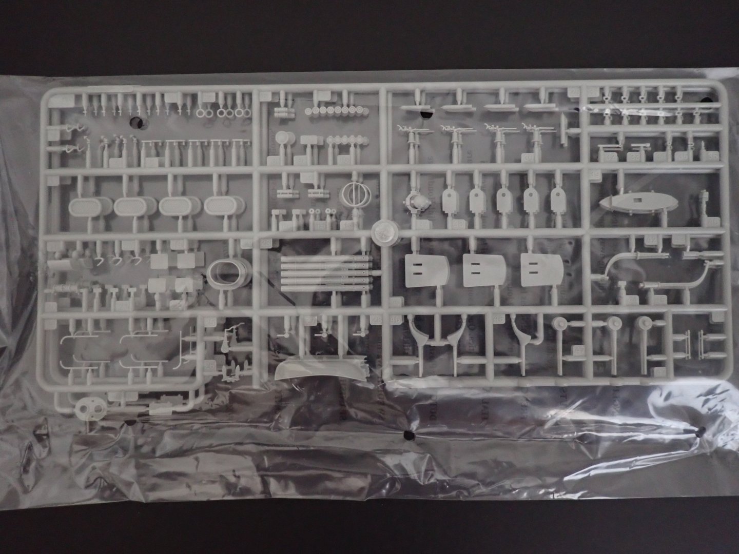
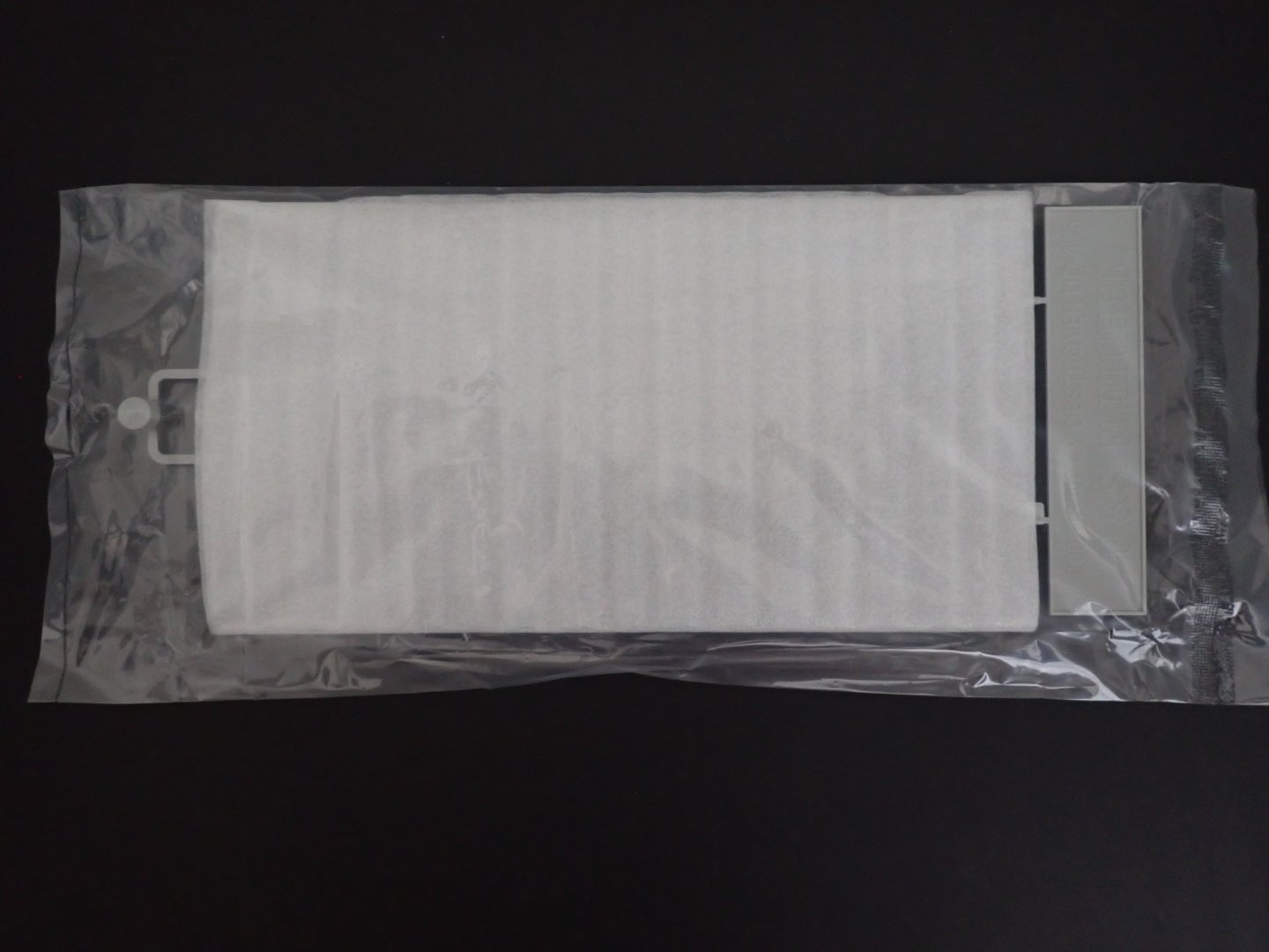
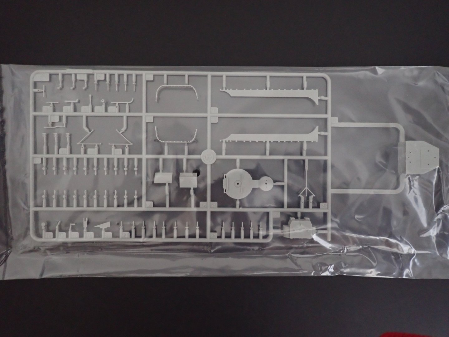
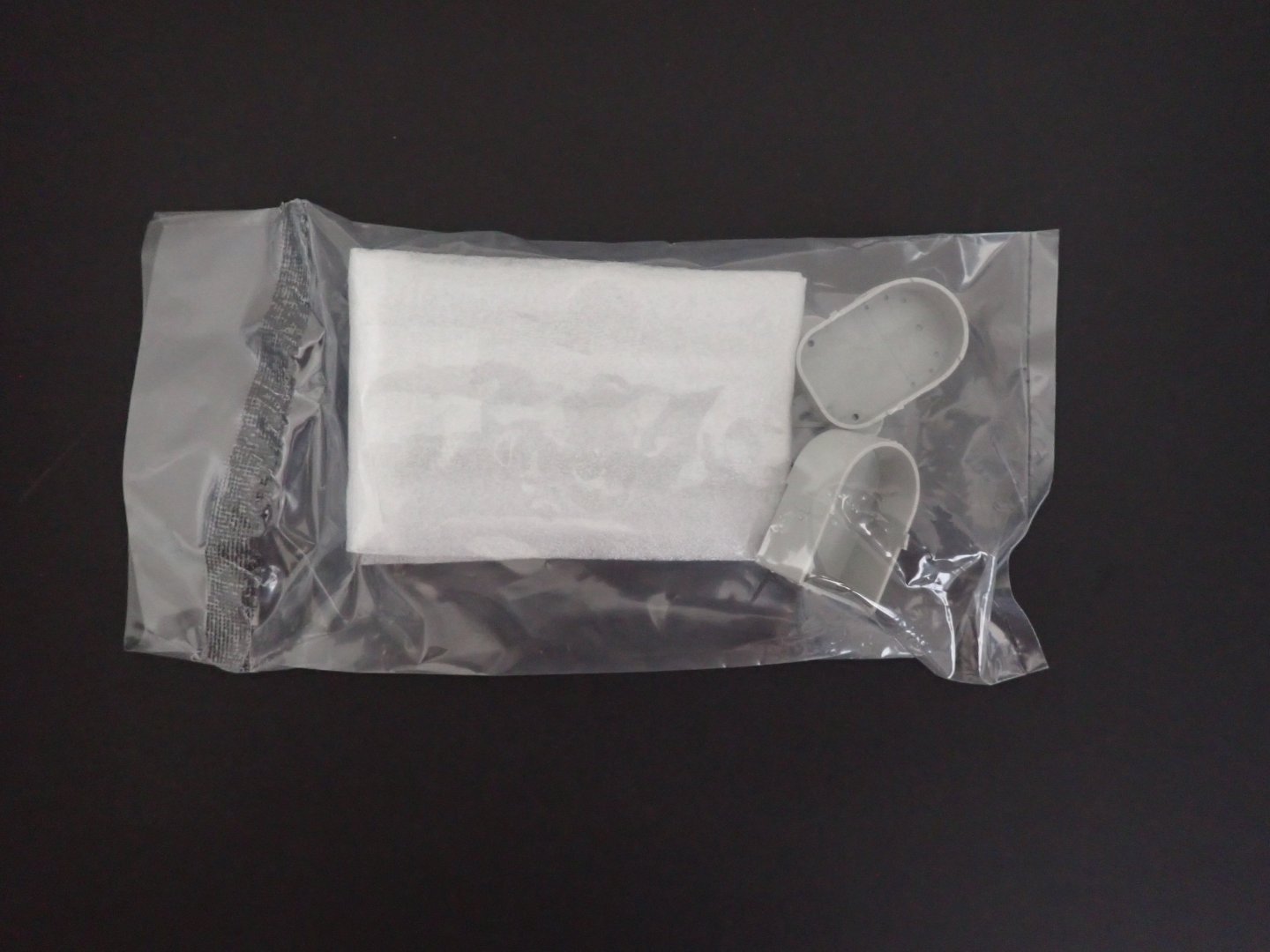
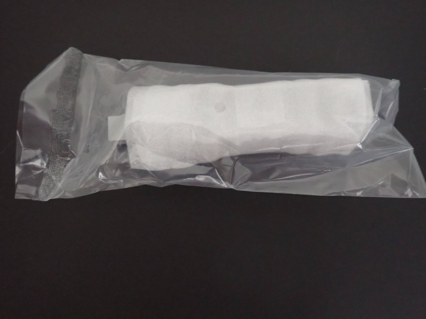
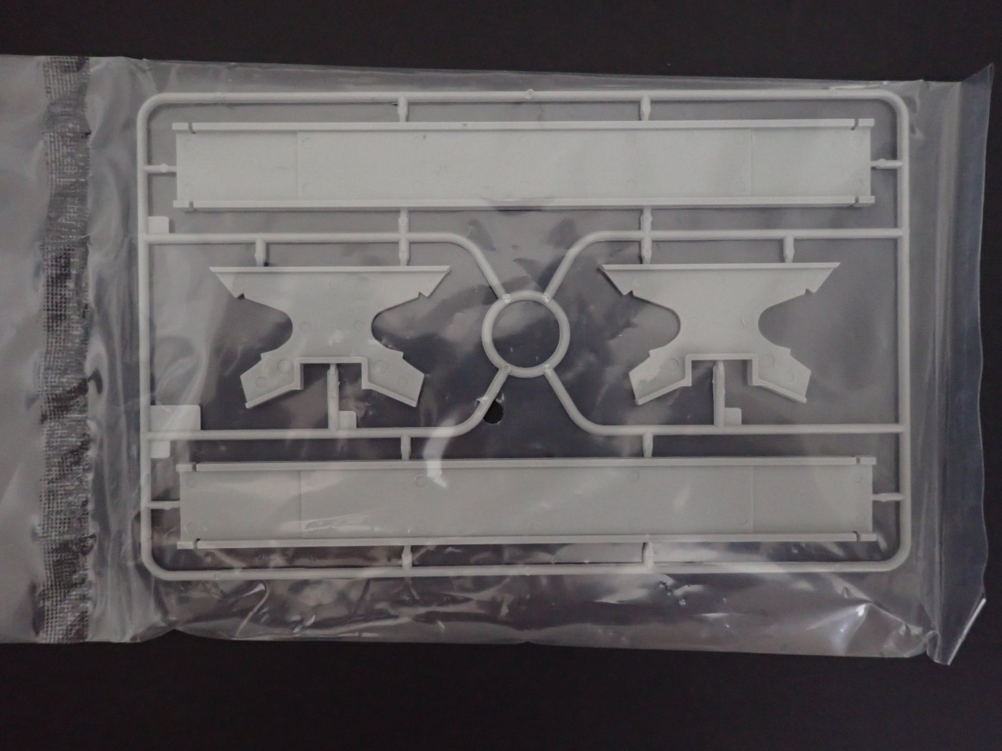
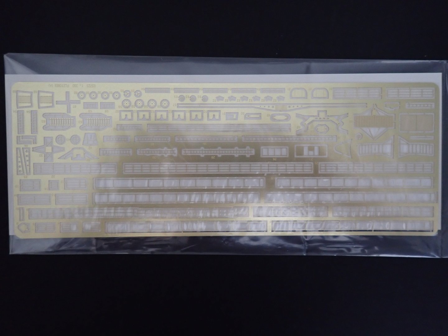
This is a quick presentation of the latest 1/200 kit from Trumpeter. I have two Japanese, one German ships at that scale and thought that I should also have one American vessel. I always wanted to build the kit from Lindberg about that famous Destroyer, but could not resolve myself to spend time on such a crude kit. When Trumpeter announced the production of the DD-445, it was worth investing into it (I got my kit from Squadron for less than $99.00). Of course, the Lindberg kit designed for flotation is much bigger, but the Trumpeter kit will fit nicely with the other ships I have. The box is very well presented and organized, as is the case with Trumpeter. As is the case with Trumpeter, the instructions comes with a nice double pages, showing the colors and paints required to finish the model. Two schemes are proposed: The first page shows all the parts available in the kit: A large sheet of decals is provided: Hull and deck are pre-packaged together: Two sheets of PE and a length of chains, are also included: I believe this little kit will be popular among the modelers. Trumpeter was planning to provide three different types of destroyer of that same class. We will see if they implement that idea, all the way. Yves


-
- 10
-