


SJSoane
-
Posts
1,641 -
Joined
-
Last visited
Content Type
Profiles
Forums
Gallery
Events
Posts posted by SJSoane
-
-
A good day of drawing. Now I understand this complex structure more completely, I am just about ready to start mocking up some parts on the model!
Mark


- Beef Wellington, gjdale, mtaylor and 7 others
-
 10
10
-
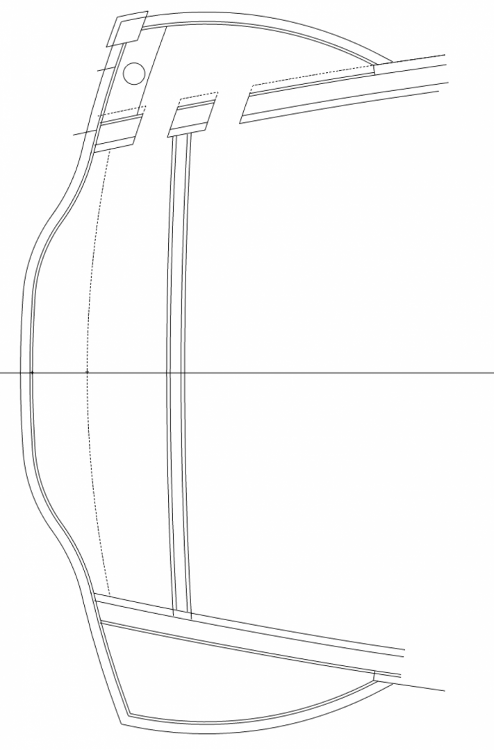
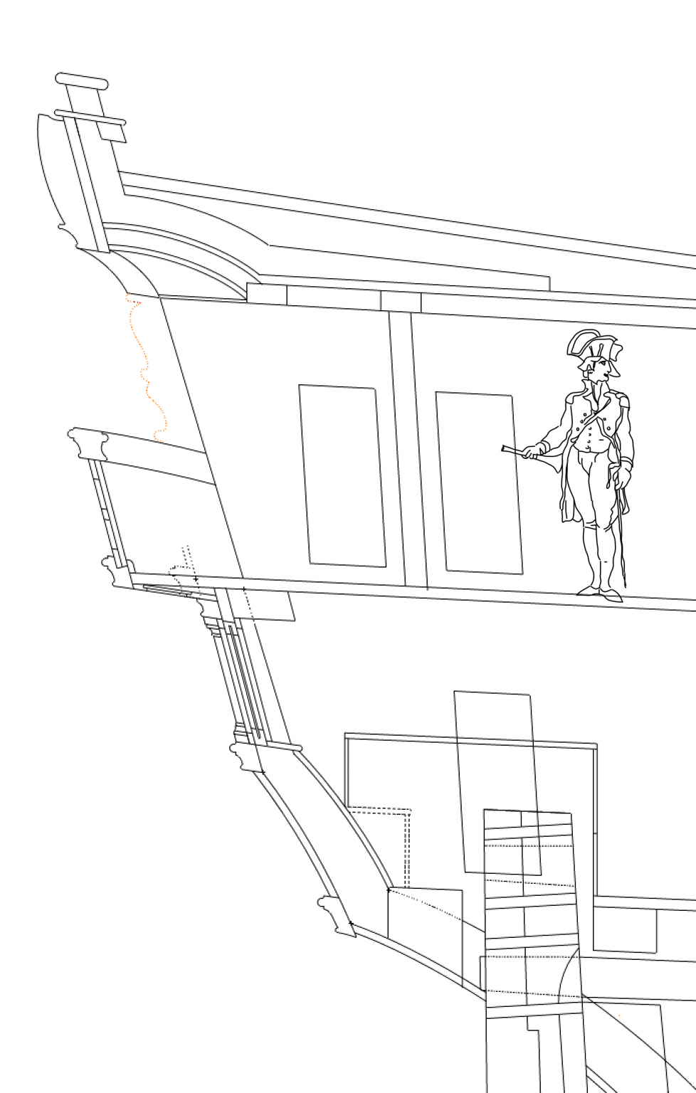
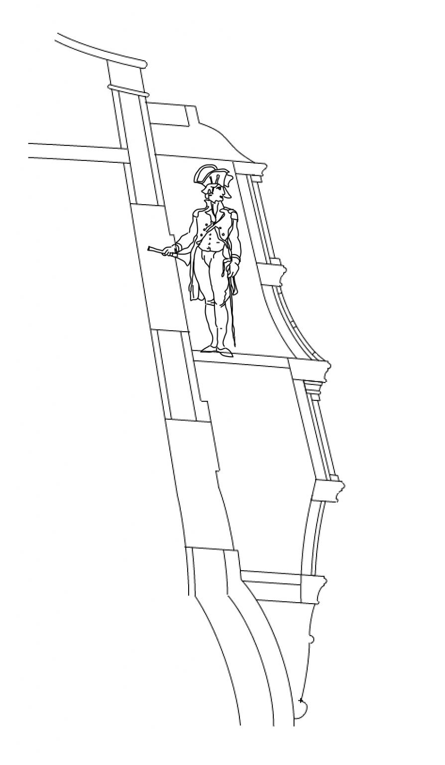
I am drawing the section through the quarter gallery, learning much about how these were constructed. This shows just how tiny these spaces really were. And look at how short the doors are, to the left of each space. I wonder why these were not made taller?
So a quick question came up about the upper finishing, or the roof over the quarter deck. Steel says, "the upper and lower finishings may be found at pleasure, making them as light as possible, to please the eye, and containing sufficient room in the upper finishing to hold a cistern." (p. 365). I am showing a recess in the finishing below. Does anyone know what the cistern was used for? Was this a primitive flushing device?
Mark

-
Beautiful work, Siggi. And I see you have your master carpenter in the chair in the conservatory. Time to get back to work!
Mark
- Siggi52, mtaylor, Keith Black and 2 others
-
5
-
Thank you, Gaetan, this is good advice.
I am quite uncertain about how I am going to construct this balcony railing, with its lacy decorative pattern on a serpentine curved surface. I was originally thinking that the railing might help give shape to the lower surface. But I have no idea how I would cut that notch. If I made the lower surface solid rather than pierced, then I could shape it maybe by laminating layers of thin wood to the right curvature, and then it would not need the railing to make its form. I think this is going to take a lot of trial and even more error.
I highly value your advice on construction details. You are the master at that.
Best wishes,
Mark
-
Hi druxey,
I am thinking I need a little help with an obsessive/compulsive disorder....😗
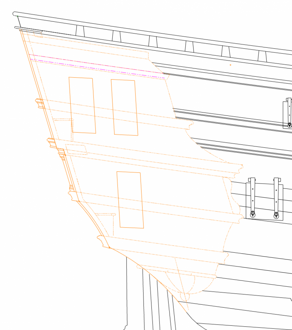
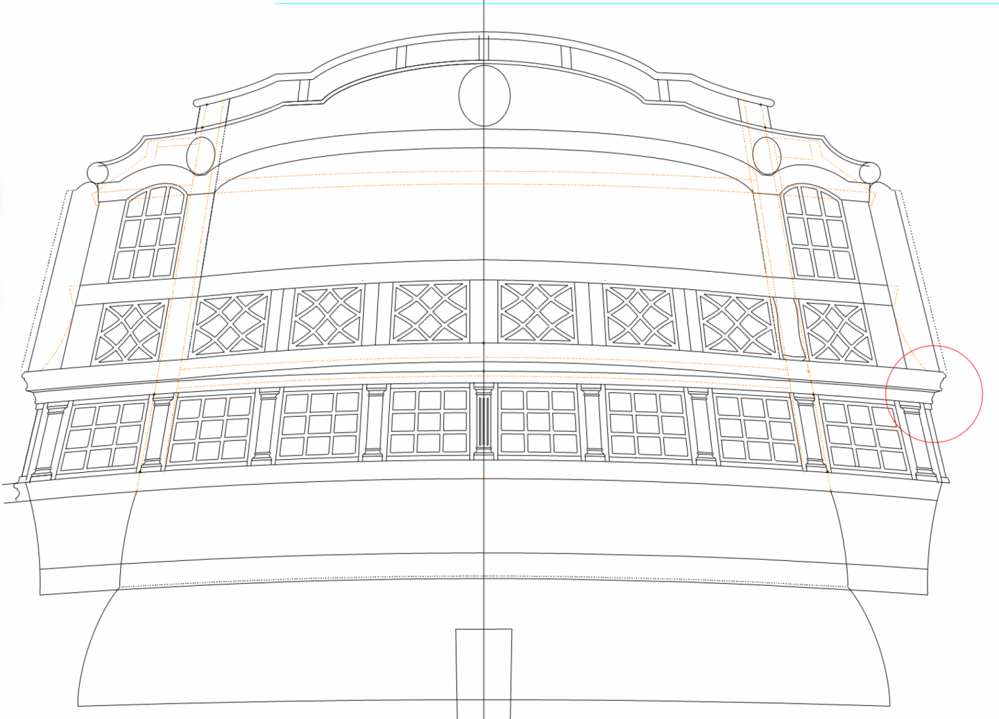
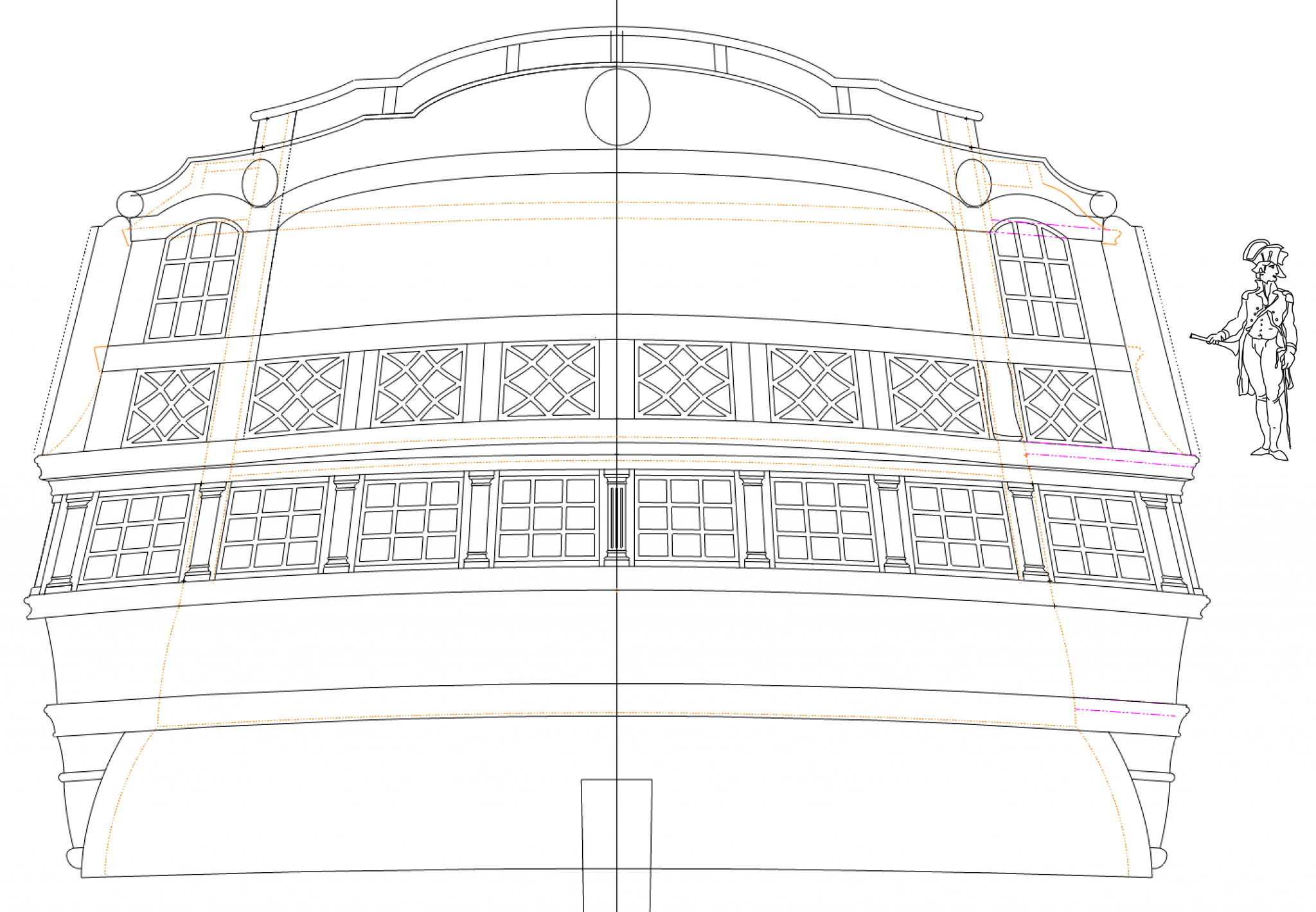
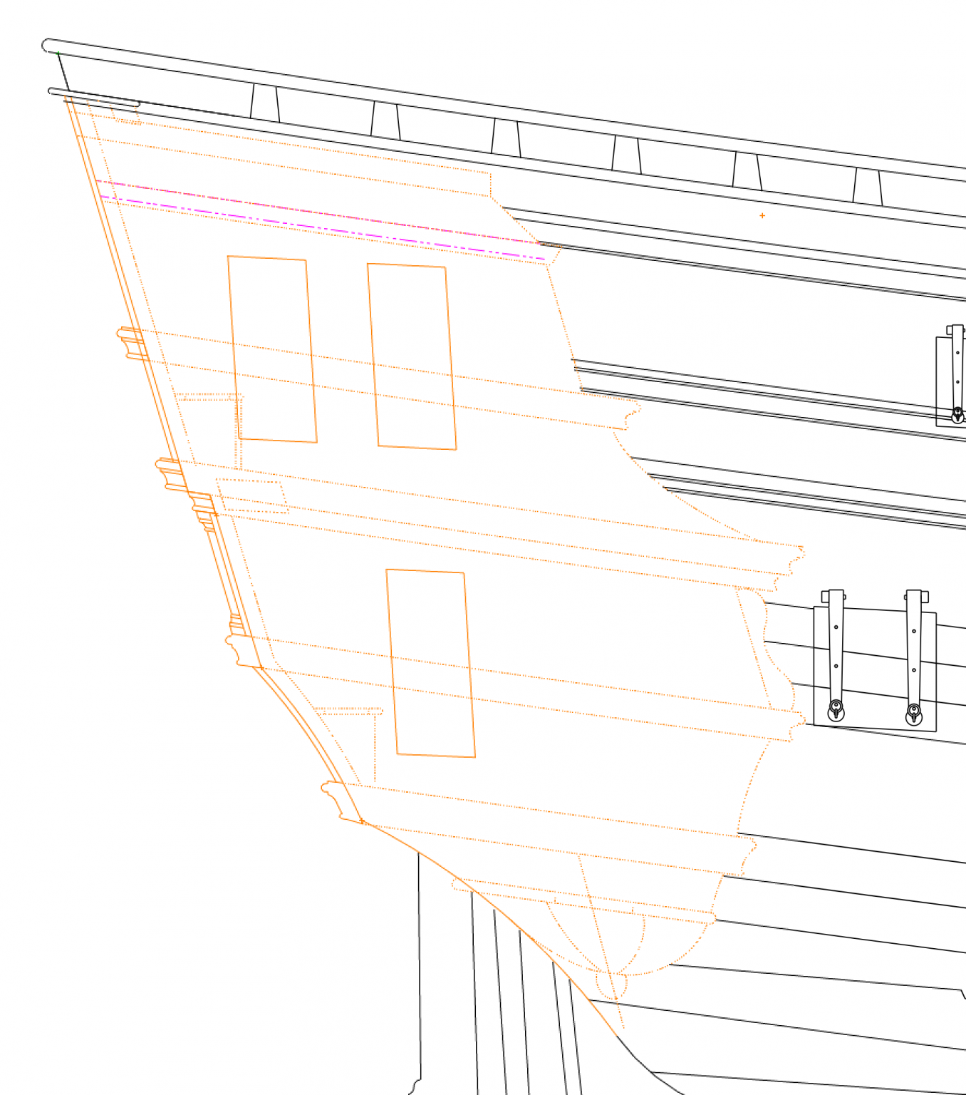
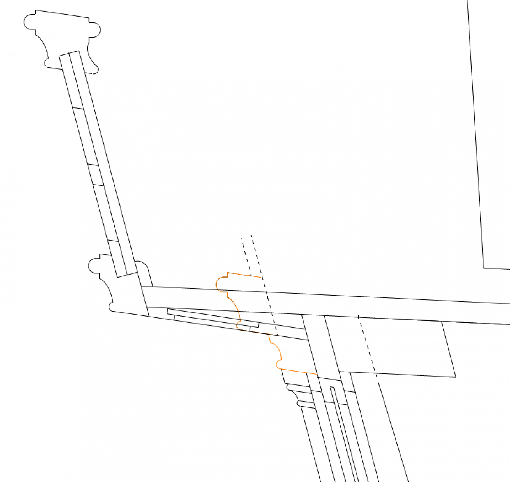
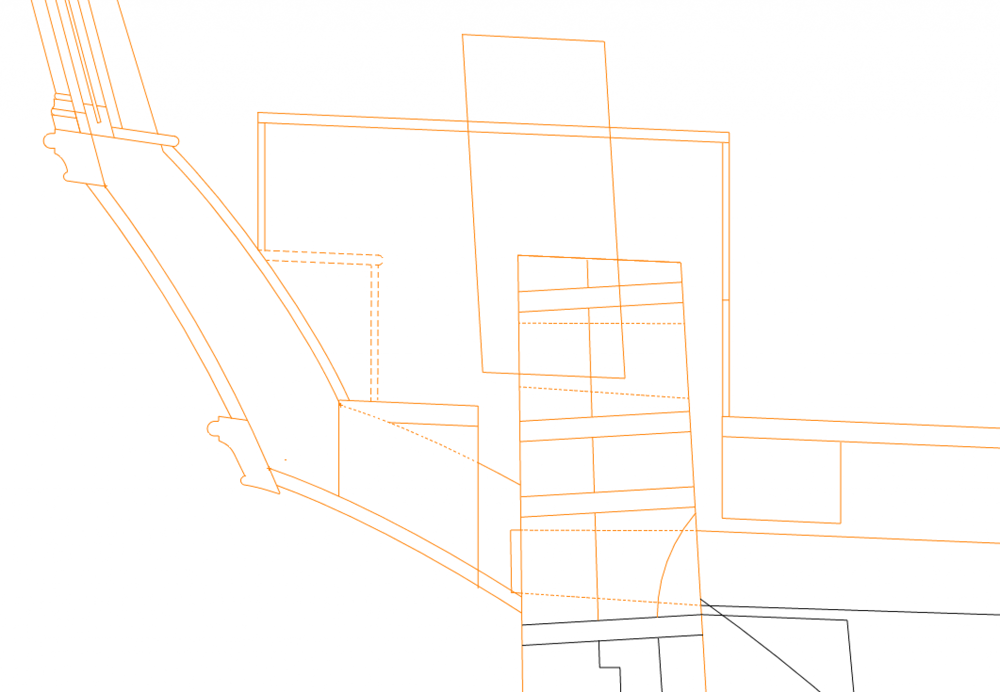
Actually, there was some method to the madness. I am having to reconstruct the stern only from the evidence of the photos of the two models, and the original admiralty drawings which I now know are not very consistent with the models in regards to the stern. I discovered that the key foundation for this stern is the line of the mouldings at the edge of the balcony deck. You can see in the original model that the hull frame projects out six inches, like a notch, just below the balcony deck line.
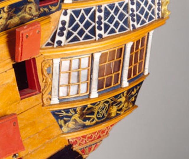
It turns out that this notch is lower than it should be, compared to the later model. In the later model, we can see that the notch is used to jut the upper stern works 6" further aft of the windows below, forming a little overhang over the windows, all the way to the sides of the quarter galleries. We can see this here, as a heavy shadow line just above the windows:
In this detail, the lower orange moulding is below the notch, while the upper orange moulding is above the notch.
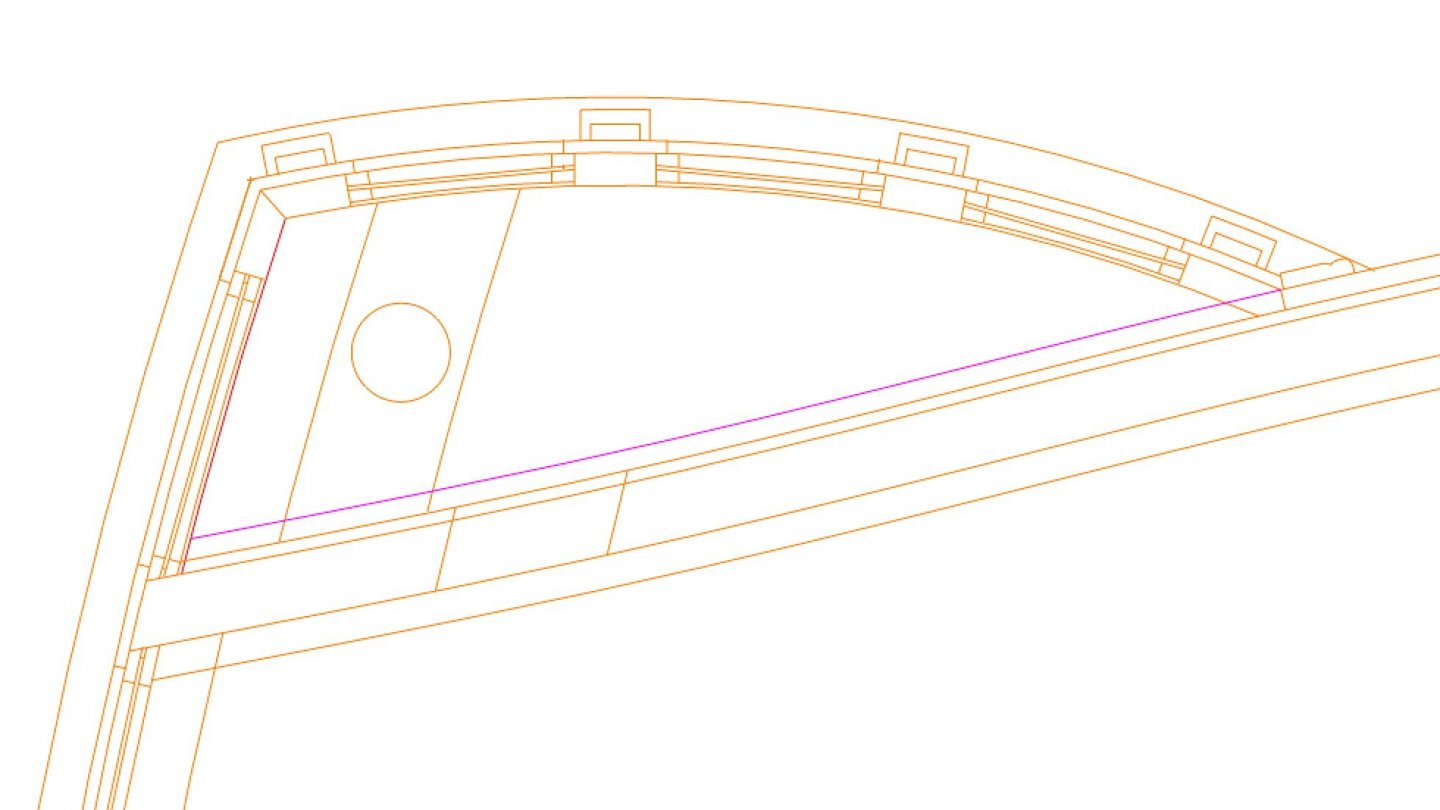
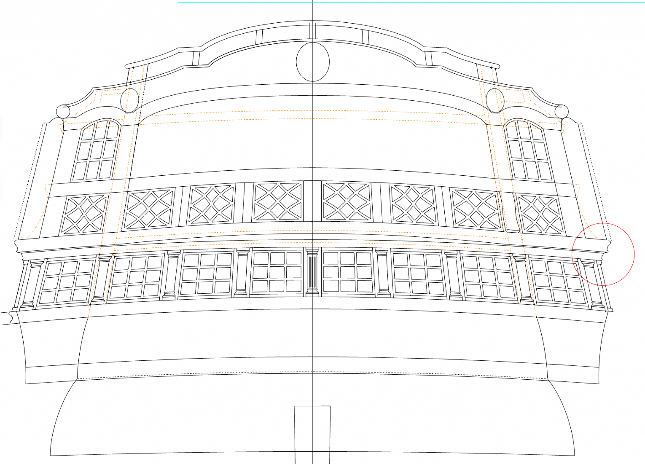
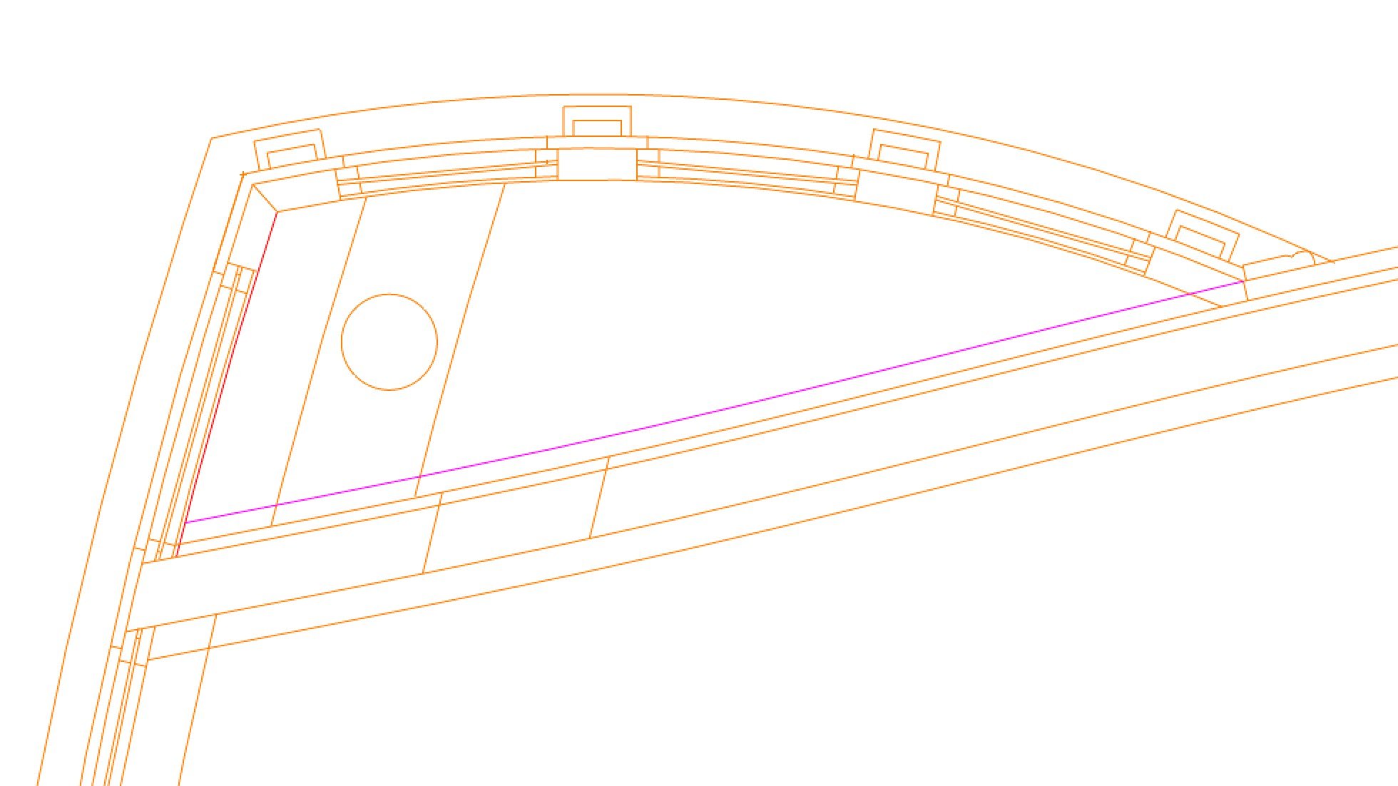
However, once we turn the corner of the quarter gallery, the two mouldings are brought back together without the 6" offset. Now, the width of the overall upper works are determined by how far out these mouldings project on the side of the quarter galleries, as indicated with the red circle below. When I didn't understand what the mouldings were doing, this projection on the side varied by a considerable amount as I experimented with various moulding profiles, throwing off all of the proportions of the upper works. So, now I have a solid foundation for reconstructing the rest.
-
For geometry nerds only:
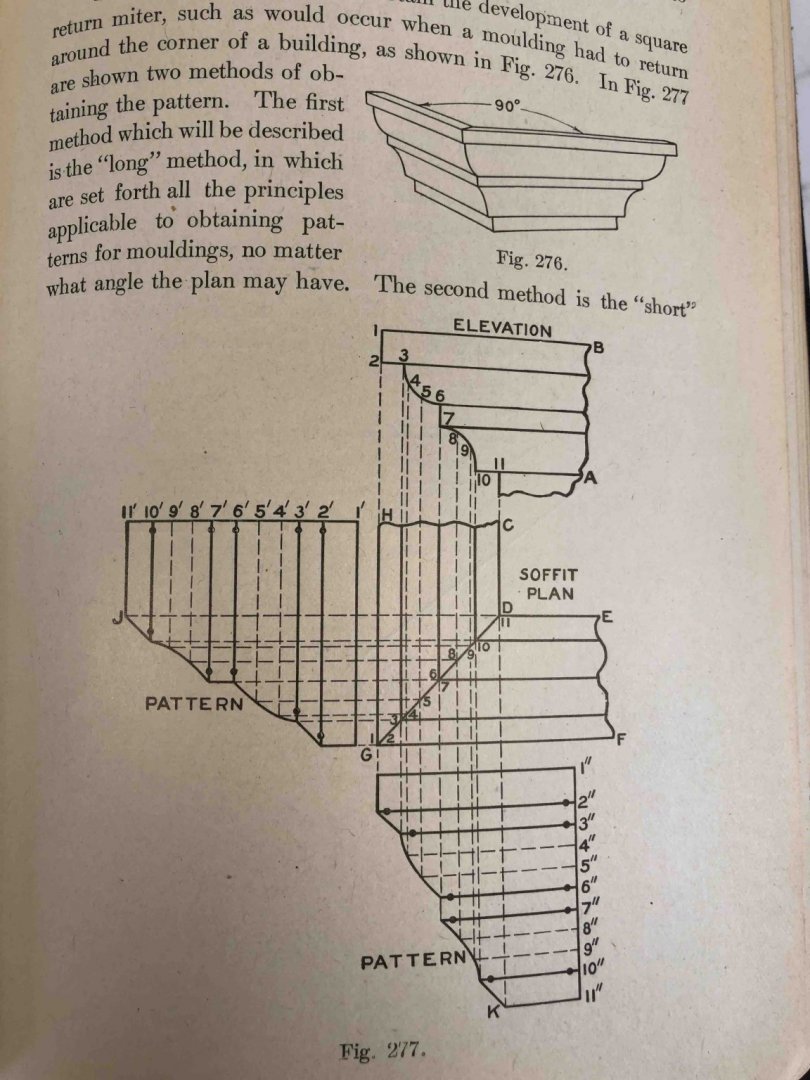
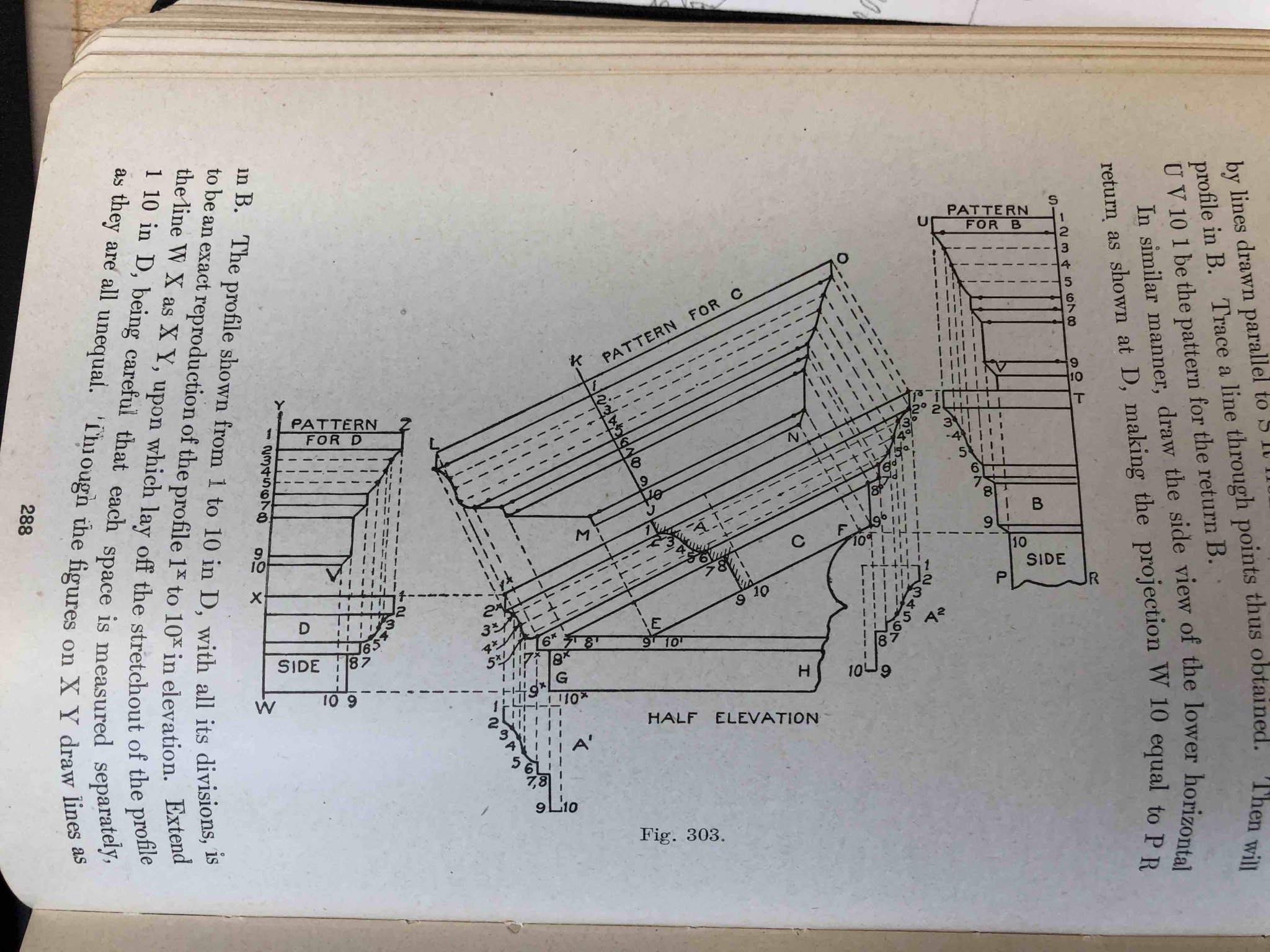
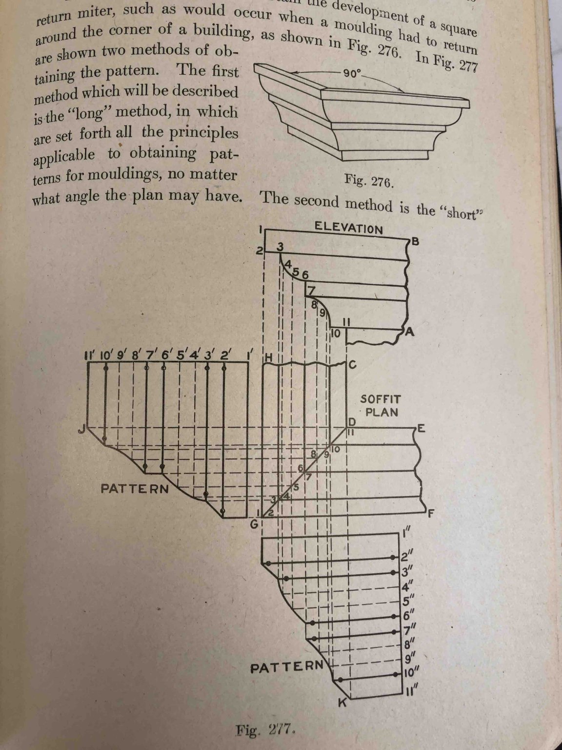
I woke up at 3 in the morning, suddenly remembering that traditional classical architecture has long dealt with how to wrap complex mouldings around a variety of forms. I dug out an old drawing book from 1919:
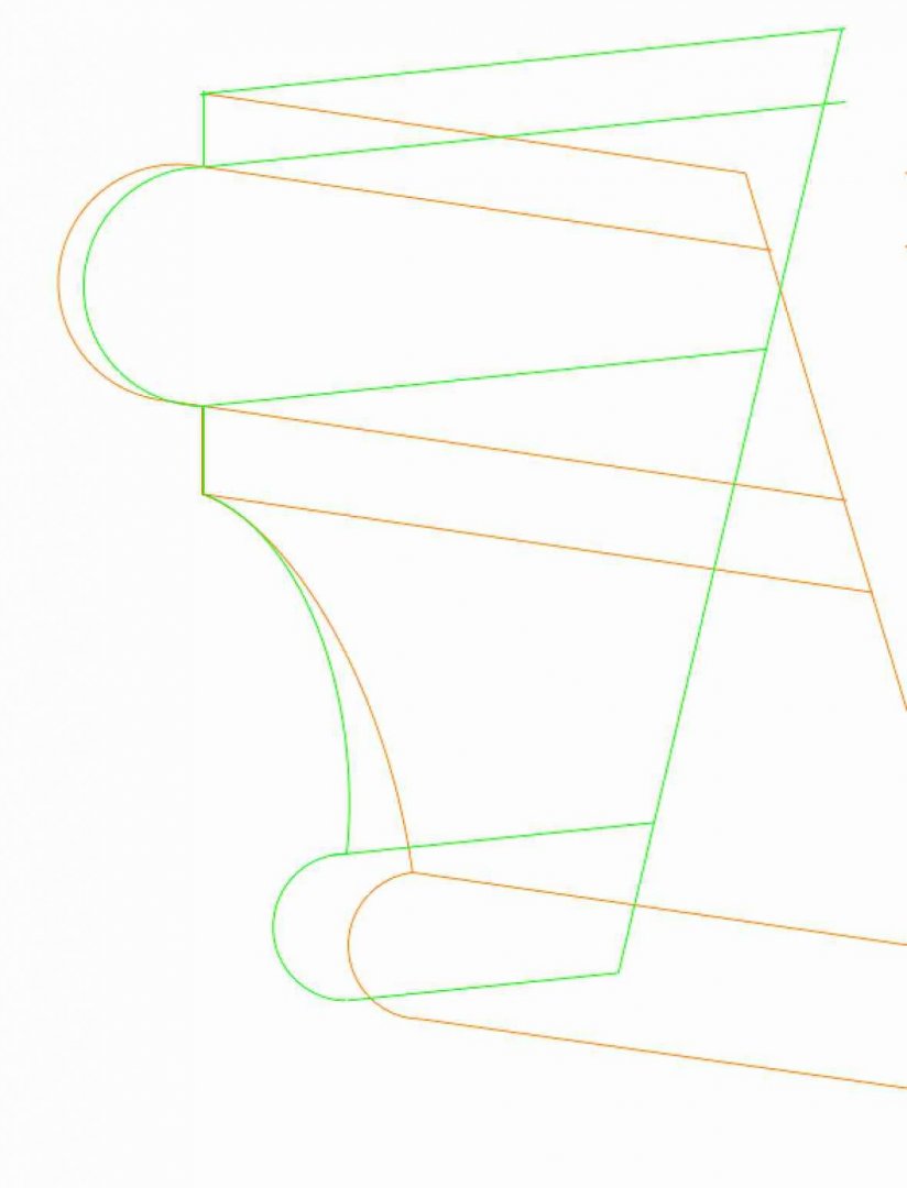
It reminded me that classical mouldings change their profile when they run into a surface not in the same plane, like a pediment moulding running down on an angle and then hitting a vertical wall. This book shows how to determine the profiles at various places.

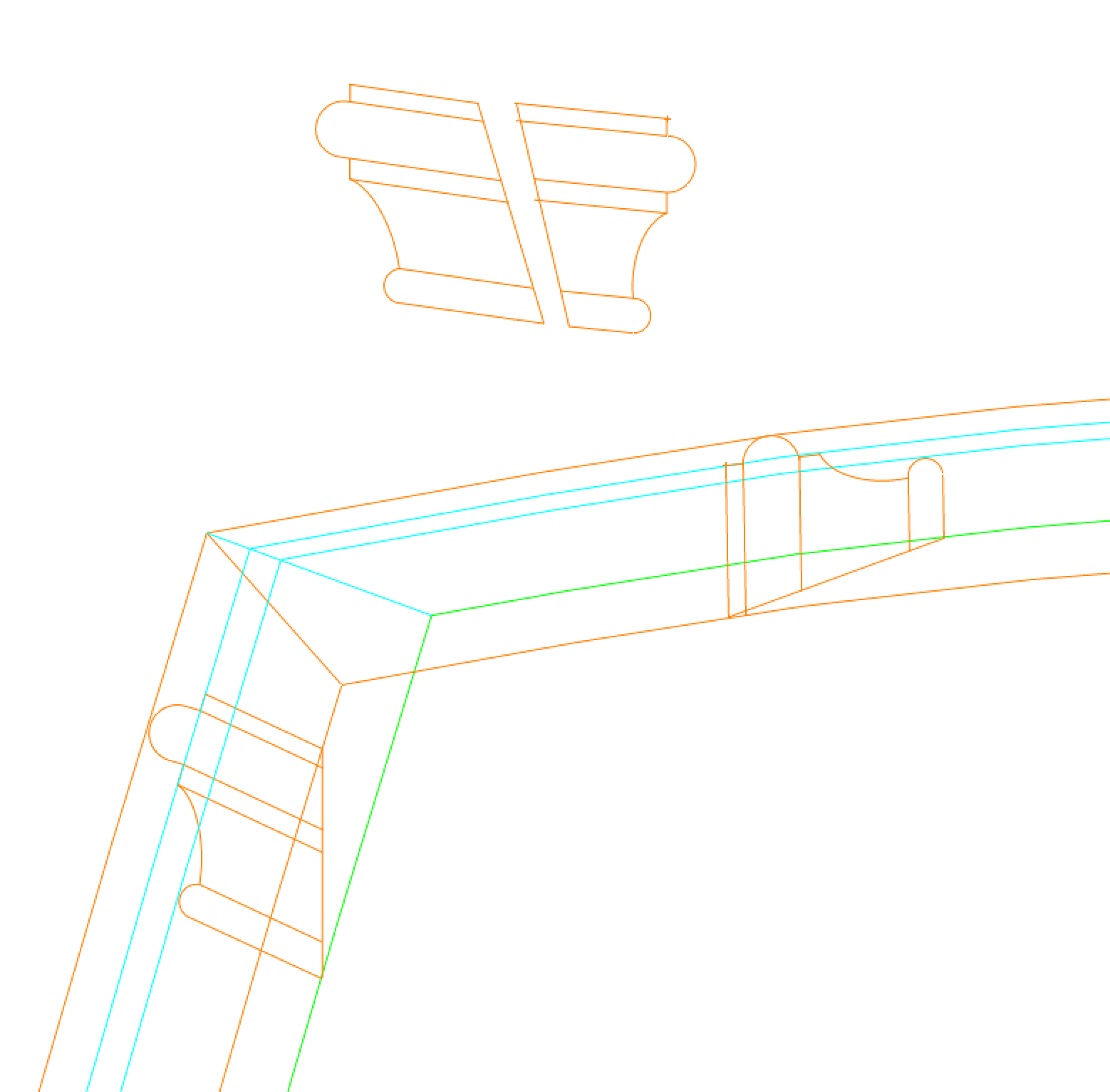
The key to working this out is realizing that in plan, the various lines of the moulding have to match up at the line of the miter. In the drawing below of a quarter gallery corner (stern to the left), the brown line represents the edge of the moulding at the top, the green line represents the moulding at the bottom, and the blue lines represent the lines of the various moulding pieces like the vertical fillets. Since the moulding at the stern rakes back and the moulding at the side of the quarter gallery rakes in, the overall width of the moulding at the side will be narrower than the moulding at the stern. Furthermore, the top line of the stern moulding is aligned with the sheer of the hull, while the top line of the moulding at the side aligns with the roundup of the deck. When these all match up, then the profile shapes change relative to each other. The top two drawings represent the moulding at the stern and then at the quarter gallery respectively.
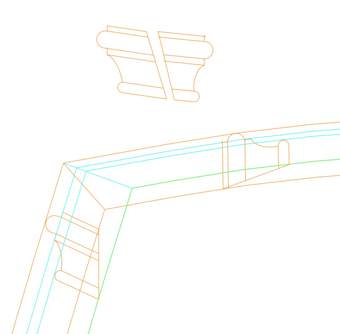
Now at 3/16" scale, the difference between these might be minuscule, probably outside my technical abilities to make different. One scraper might do the job for both. But it is finally satisfying to understand the true geometry, as the shipwrights would have had to work out on the real thing.
Here is the difference in the actual profile edge:
Geometry lesson over, you can go back to your regularly scheduled programming!
Mark
-
Marc, thanks so much for sending that video of the Victory. Fascinating to see some of the detail close up, and it is always a good reminder of how large all of these things are in the real ship, as opposed to our relatively dainty models. When we think about all of the details that are discussed on this website, and then think about how big they were in real life, it gives one an even greater appreciation for those shipwrights.
Mark
- druxey, Hubac's Historian and mtaylor
-
3
-
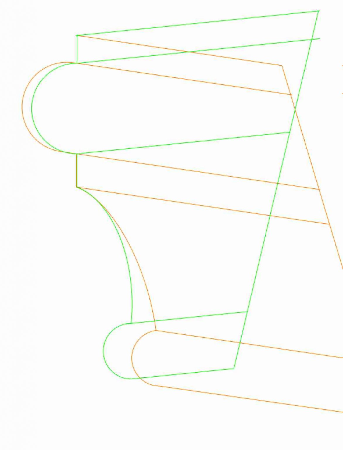
So, I think I see it now, thanks druxey. I think the blanks for the mouldings at each location have to be shaped with a different back, to match the surface upon which it sits. The guide is the moulding on the stern, which will have a horizontal top surface. The ones on the quarter galleries then align to this, with a different back angle. And, the mouldings at the sill of the window are different in their back angle than the ones at the window head, because they sit on different raked surfaces. In the drawing below, the green moulding at the left (top and bottom) is the profile swept along the moulding, which keeps the top horizontal to the ground. The green mouldings on the right (top and bottom) are what I believe will match along the quarter galleries. I may have to make up some samples to really see this.
- druxey, Hubac's Historian, mtaylor and 3 others
-
6
-
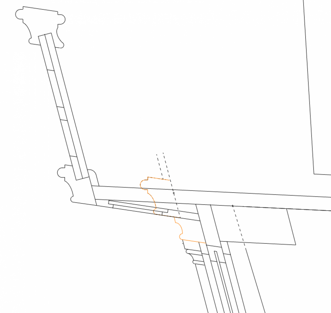
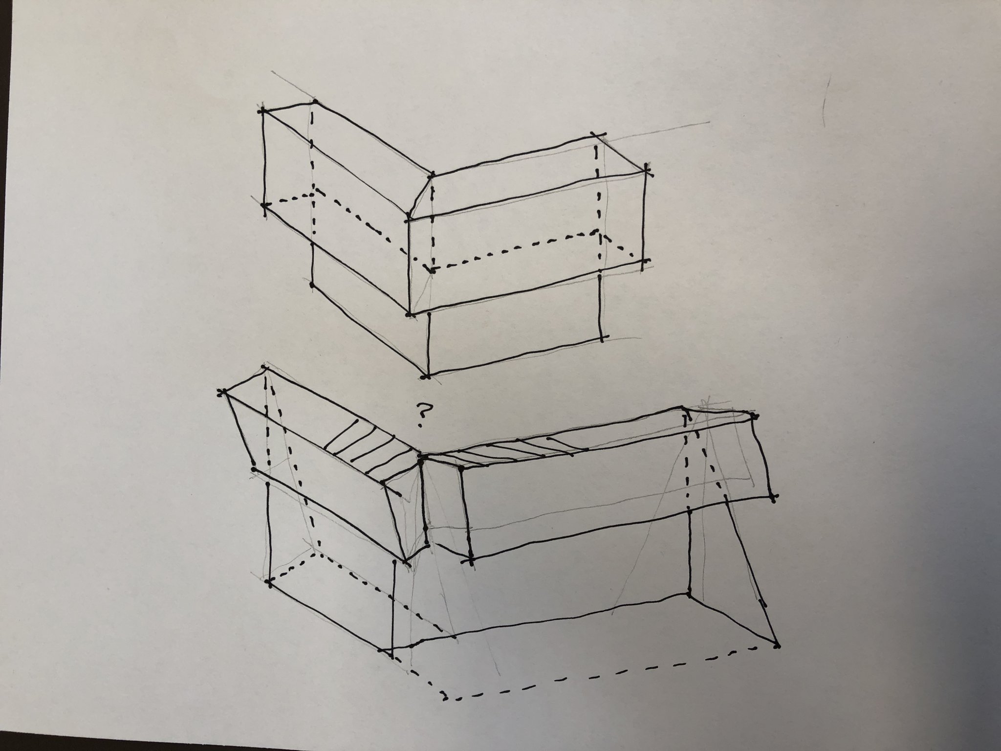
Hmm, I will get back to the stern frame in a little bit, but this morning I am struggling visualizing the mouldings that wrap around the stern to the quarter galleries. The stern slopes one way, and the side gallery slopes the opposite. In this image, the same green moulding is aligned with the rake aft to the left, and the rake of the quarter gallery to the right. These won't form a clean miter at the corner. The orange moulding shown here works for the rake of the stern, but has to be changed entirely in its profile to fit the quarter gallery, because it upward sloping surface has slope down on the side gallery to match at the corner.
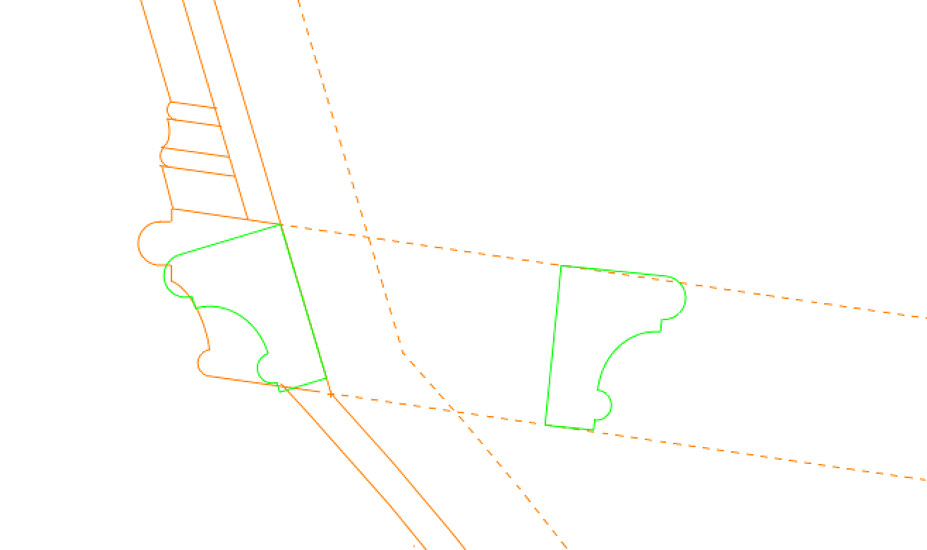
The problem with the geometry is shown here. The upper diagram is a clean miter when both sides are the same rake, in this case vertical. The second diagram shows what happens with the left piece rakes aft, while the side piece rakes the other direction. The two can't form a clean miter. And yet, there are thousands of models that do this. Can't visualize it!
Mark

- GrandpaPhil, mtaylor and paulsutcliffe
-
3
-
Hi Gary,
You are right. I can't see how to fit a transom behind the rudder that has any thickness to it at all. Below shows the plank running into the fore edge of the stern timber. A transom would really just be separate blocks of wood between the stern timbers, not a continuous structural member across the width of the stern.
That triangular block of material directly behind the rudder sitting on top of the stern timbers really has to be something like a chock or something to fill this space, I would think to keep water out of this area. Many years ago, I see I made a big chock behind the rudder hole, the same thickness as the stern timbers at this area. I think it needs to be filled up more to the deck level somehow. I believe the flat spot I made on this chock below is at the level of the top of the beams, so there really isn't room for a transom. Well spotted! So maybe it is a nailer on the tops of the stern timbers that the planks sit upon, either side of the rudder hole.
Do you think the curved beam I am showing in front of the rudder is not plausible, given the plans you have looked at?
Best wishes,
Mark
- Captain Poison, mtaylor, GrandpaPhil and 1 other
-
4
-
Well, now I don't know what to make of the original Bellona drawing labeled as the Quarter Deck plan. The quarter gallery shown here is actually the length of the quarter gallery one deck below, off the Upper Deck:
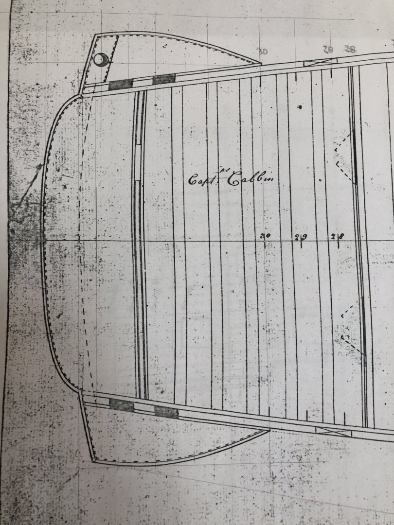
The quarter gallery for the Captain, off the Quarter Deck, is much shorter, and narrower. Indeed, it is quite tight...
This is really obvious in the sheer drawing, Captain quarter gallery off the Quarter Deck above, larger quarter gallery off the Upper deck below:
So, druxey, it doesn't look like this plan is very reliable evidence of anything, including the 1 1/2" planking around all sides of the quarter gallery shown in this plan. Curious why this is drawn this way...
Mark
- GrandpaPhil, mtaylor, JpR62 and 2 others
-
5
-
Hi druxey,
Thanks for the confirmation about the rakes changing from side to center. It took me several days of trying to get them parallel, and parallel they would not go! I now see that the stern assembly is in fact a large cylinder tilted backwards (same radius at each deck), with each higher deck cutting a little more aft into the cylinder because each is narrower. So obvious, why didn't I see it?🤪 I am frankly astounded at the sophistication of the geometry those shipwrights developed.
Yes, I think I am coming around to agreeing with the full width of planking running all the way astern. Now I realize that the drawing in posting #1652 shows 1 1/2" planking all around the quarter gallery, but it shows the seat full length without acknowledging the thickness of the structure that has to be there, which would have shortened the seat. So it is more like a diagram than an accurate expression of the construction. Another curiosity of the set of drawings.
Tomorrow, I am going to look at the captain's quarter gallery, where the room seems much narrower towards the top. A section might show just how tight it is.
Best wishes,
Mark
- Hubac's Historian, mtaylor and druxey
-
3
-
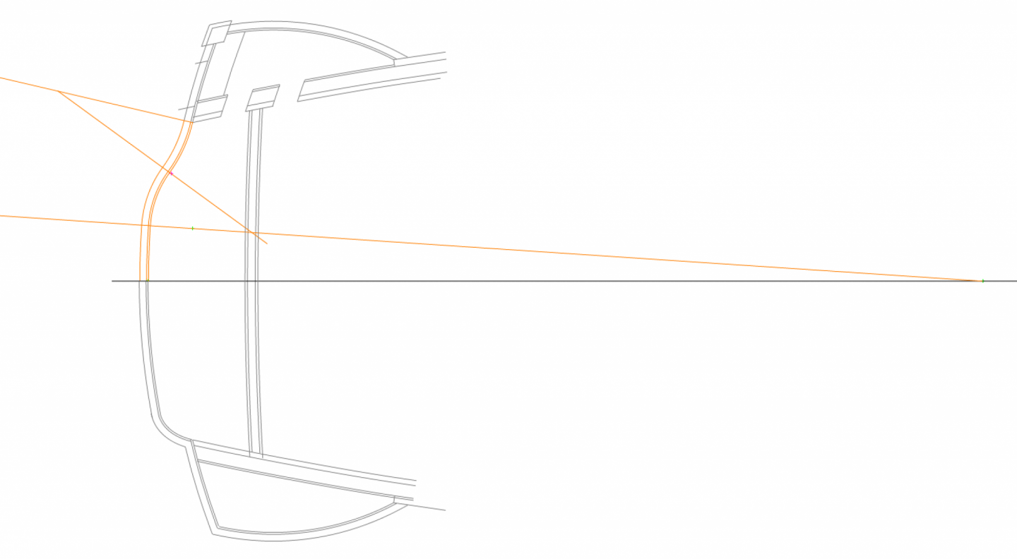
I haven't posted in a while, but I have been drawing all day long every day. The stern is definitely challenging to draw. I get the elevation worked out, only to discover that the section or plan no longer aligns. So I have to go back and forth among the three making constant adjustments. And since everything is connected to everything else, all is in constant motion...
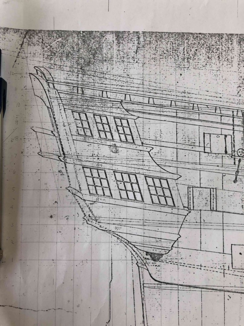
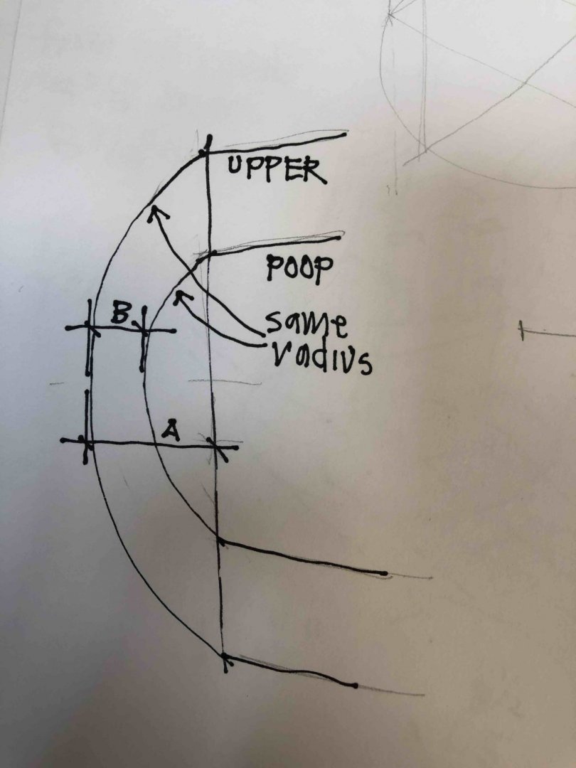
I finally figured out why things would not line up. I had assumed that on the sheer, a line drawn along the aft most edge of the hull at the sides would be parallel to a line drawn along the aft most edge of all the decks at the center line. But it turns out that the line at the sides is not parallel to the line at the center. They converge slightly towards the top. You can just about see this in the original shipwright's drawing below. Note the two dotted lines, one at the side and the other at the center, are closer together at the bottom than at the top.

I finally figured out that this is because the radius of the aft deck ends is the same for the upper deck, quarter deck and poop deck. And since the decks are progressively narrower as they go higher, the amount of round aft decreases at each deck level. And so they are progressively shorter at the center relative to their sides. The following sketch shows the idea. The two radiuses are the same, but the upper deck gets a longer rise in the chord as at "A", than the rise of the chord for the poop deck at "B" So even though the poop rakes aft of the upper deck at the side, the rise of the chord is less. So the lines at the side and the center eventually converge. A small point, but I could not make the stern geometry work until I figured this out. Those original shipwrights were pretty clever!
With that problem fixed, it is now a matter of constructing the side galleries relative to the sheer and the plans of each deck. In the sheer below, the brown lines are the locations of the various rims and stools on the face of the hull itself, while the purple lines are the beginning of the outside view of the side galleries as they project from the side.
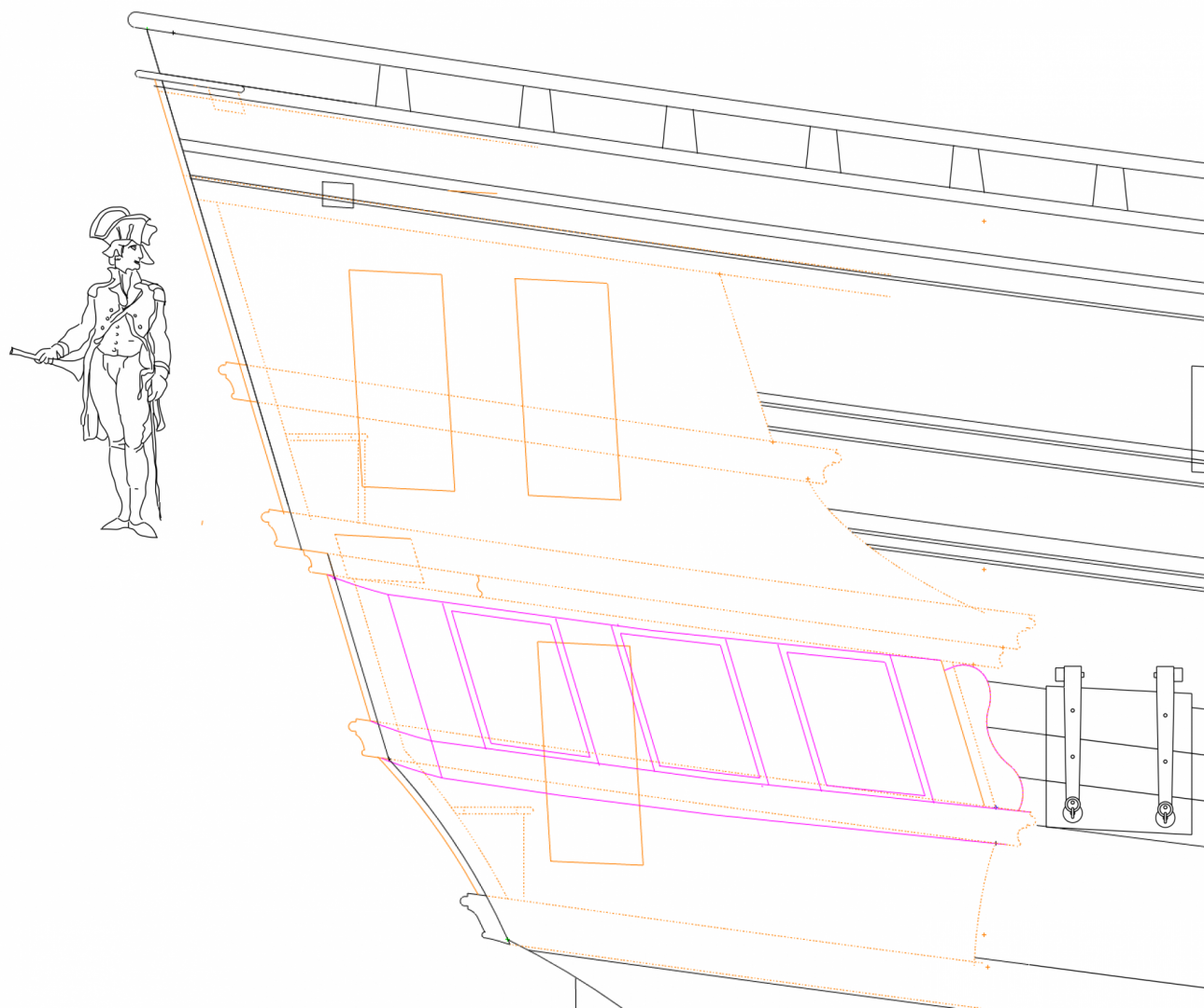
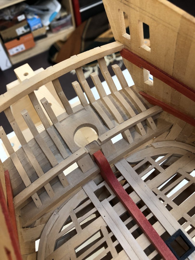
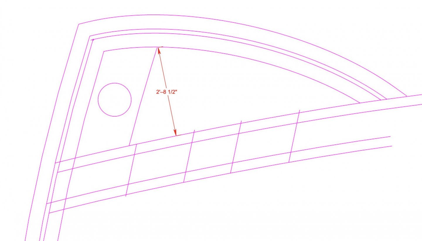
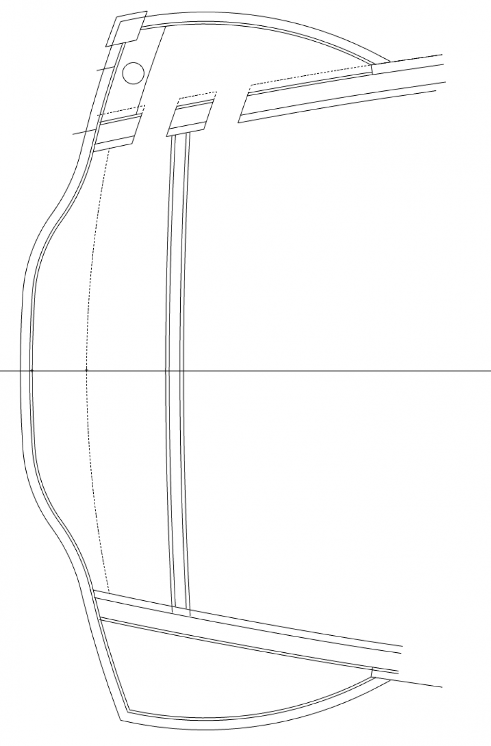
I learned more about the side galleries, working out how everything fits together. I realized that the original Bellona drawing posted previously did not include the thickness of the structure in the quarter gallery; when this is added, the space really starts to get smaller. The purple line shows the 4" thick plank within the quarter gallery; still not sure if it thins down here or not. The thicker plank definitely crashed into the stern window structure, but if there is a wooden backing to the glazing, this awkward junction would not be seen. These are snug places, 3' wide at the greatest width, and a 1'-9" door to get through into it. I am starting to wonder if there was room for a London Times newspaper rack after all...🙂
Mark
-
-
I once had an 8" industrial Delta, and more recently a 6" Rikon. I spent many happy hours adjusting them, and they were great for larger furniture projects. But I was always a little shocked watching so much very expensive boxwood coming off in order to flatten the entire 3' long board. I realized that I was trying to flatten something that was going to be cut down in length anyway, and did not need to be flattened for the full length, wasting a lot of valuable wood. Now, I slice wood to thickness plus a little spare with a bandsaw, and then run the smaller pieces through a Byrnes thickness sander. For straight and square edges, I use a good sharp plane with a shooting board. Much safer than pushing small parts over a jointer. I now never use my jointer for the ship project, only furniture projects.
But whatever works!
Mark
-
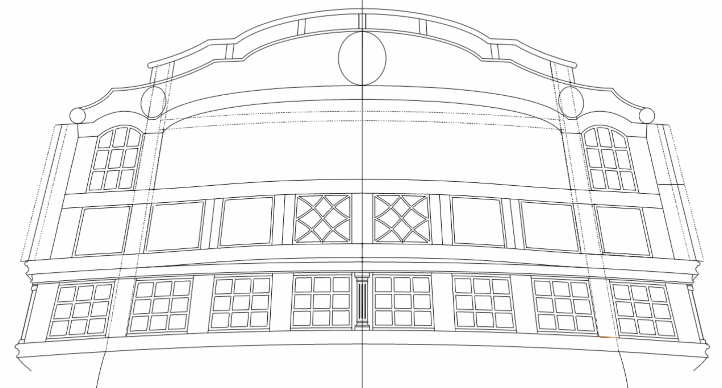
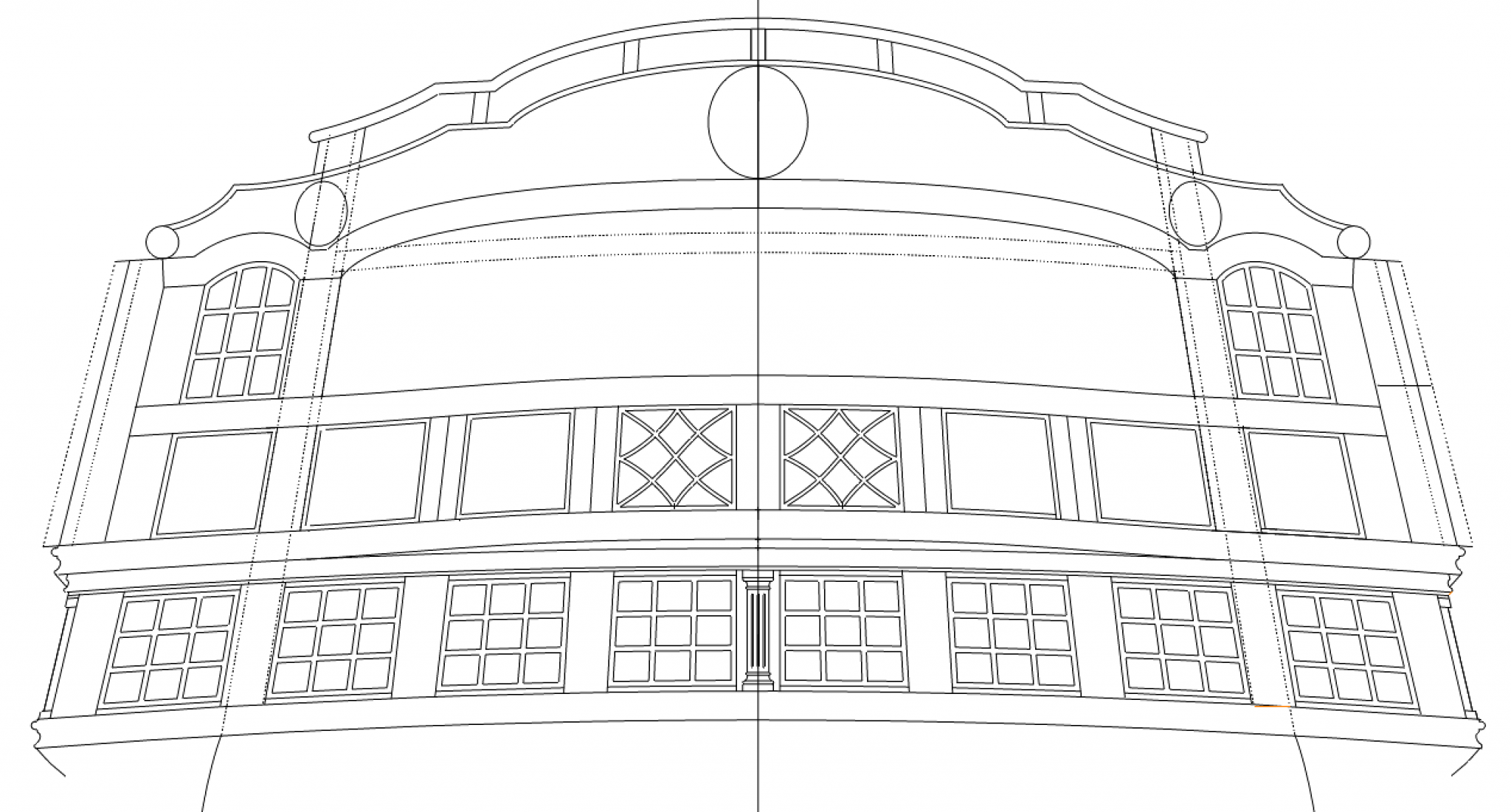
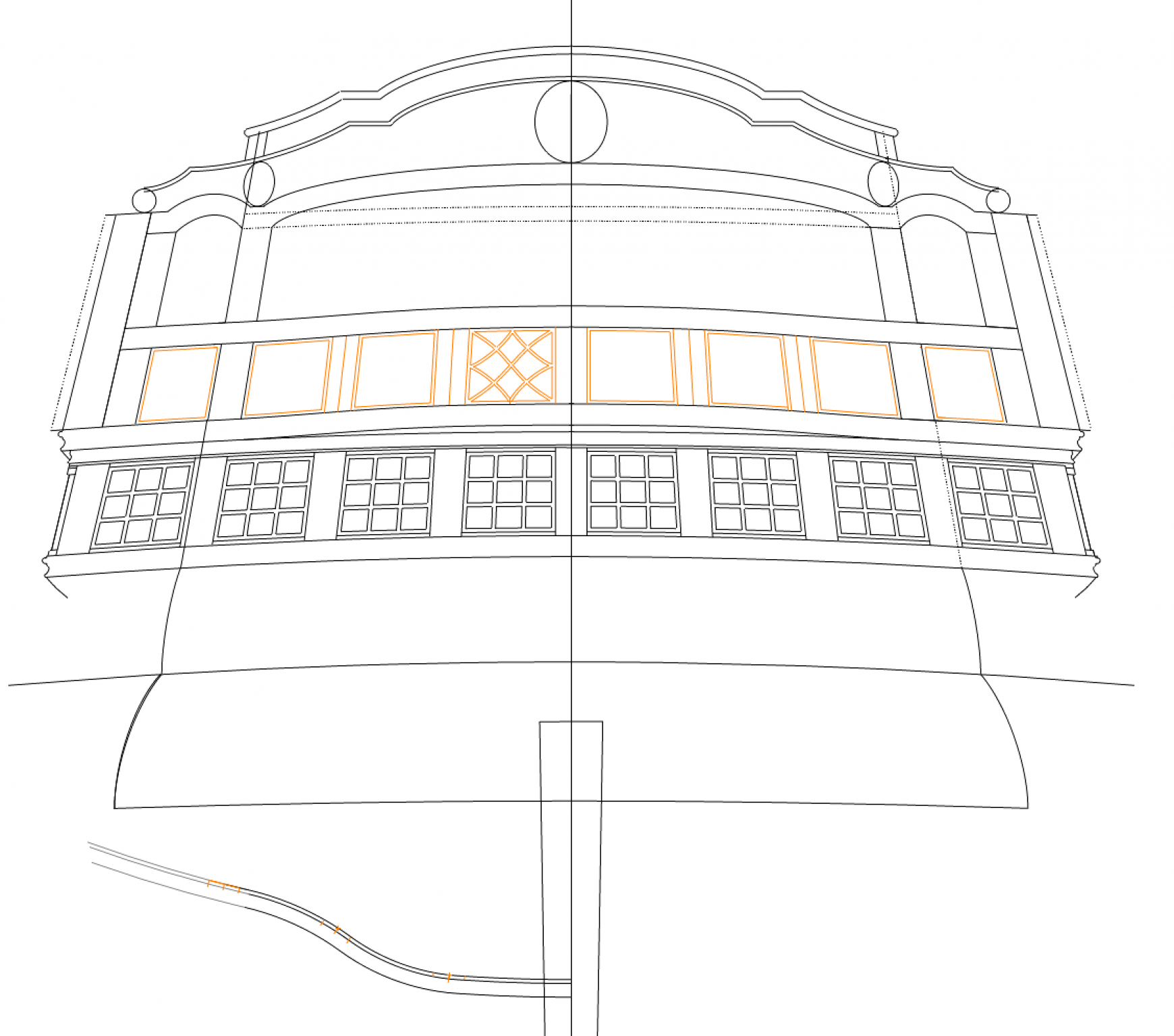
More drawing. The Bellona has an interesting cove over the balcony, which took some time to plot against the plan and section before finalizing its shape in the stern view. I am not sure yet if the curve matches the curve of the stern screen wall, or the round back of the poop deck above. A dotted line in the plan shows it matching the round back of the poop deck.
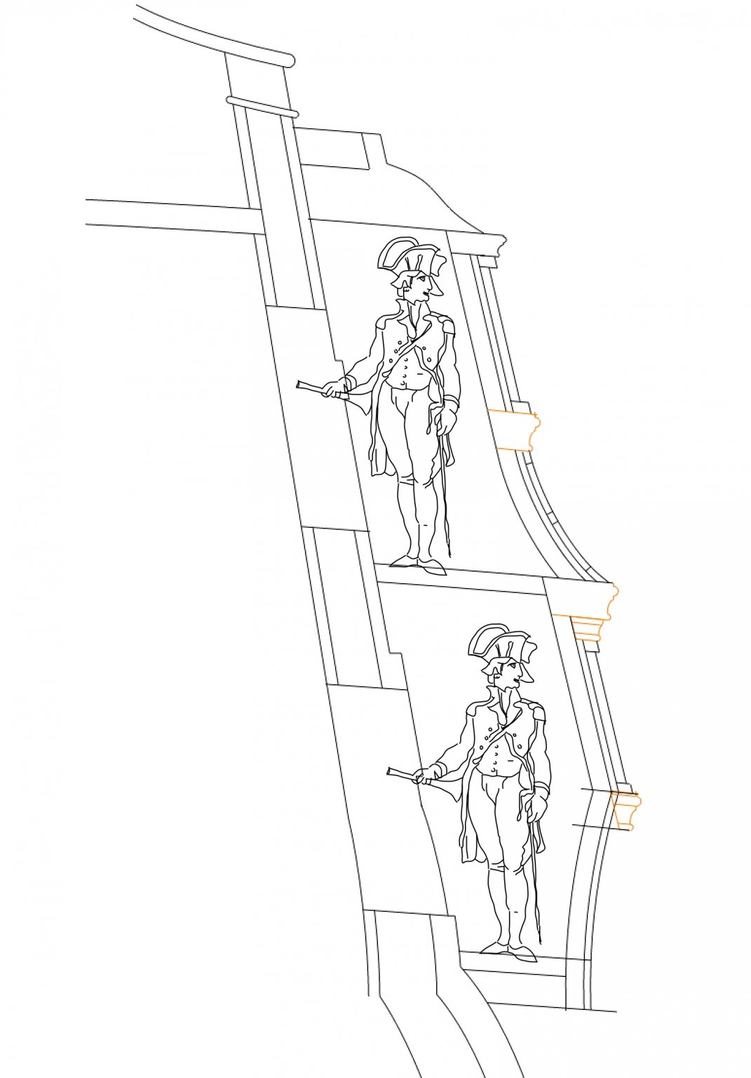
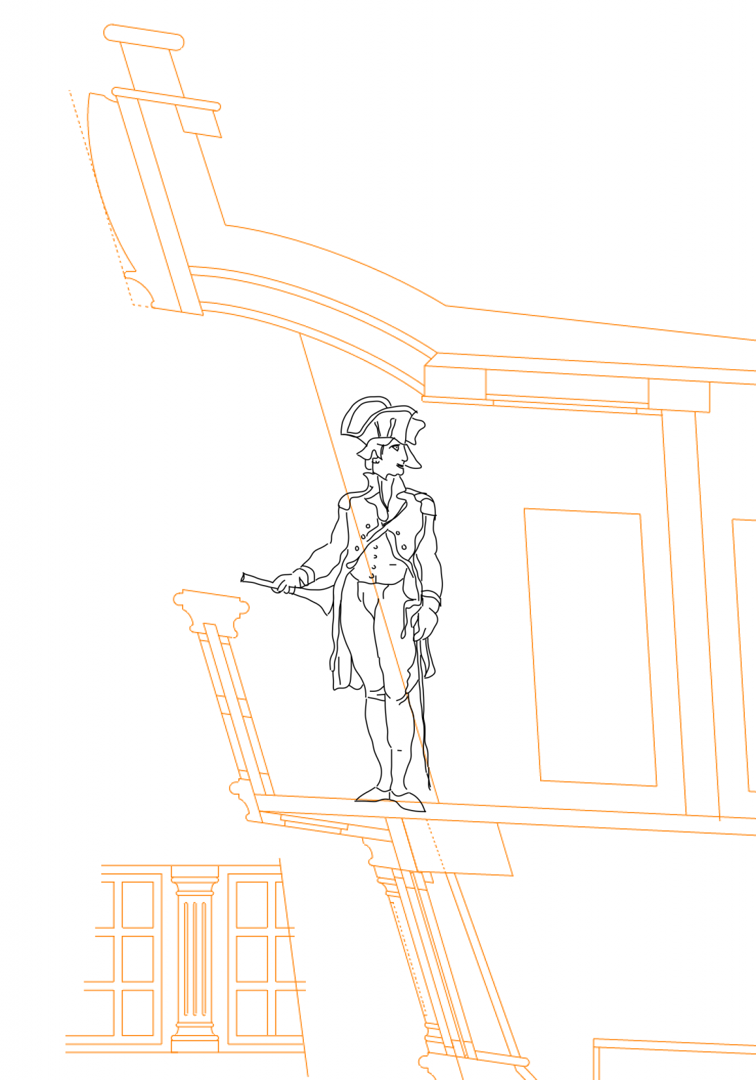
This shows how small the doors are to the quarter galleries. My captain definitely cannot wear his hat while entering. I have also confirmed that there is a soffit under the balcony deck, which is aligned with the sheer of the quarter galleries. I am showing a frame and panel system for it, as I have shown for the panelling in the ceiling of the balcony.
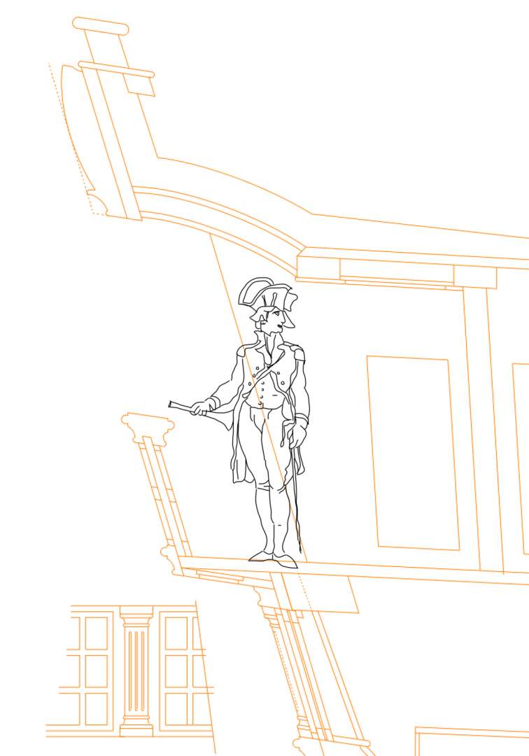
Here I am showing with dotted lines the side planking at 5 1/2" thick, coming through into the quarter gallery. It definitely makes it a smaller space, but not impossible.
And once these details were refined in the plan and section, I had to go back and change some things in the stern view. The cove had to drop at the sides, and the upper windows in the quarter gallery got shorter, both of which match better the photos of both Bellona models. So it must be getting closer to accurate!
Mark
-
Hi druxey,
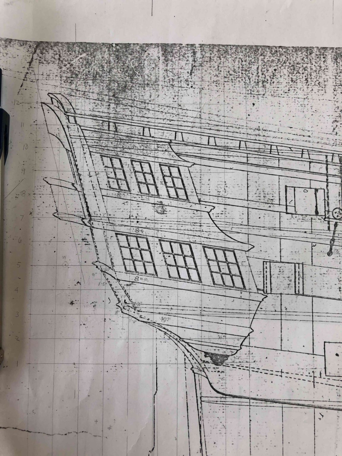
This plan was a Xerox I bought from the National Maritime Museum back in the early 1990s, before their internet postings. It is of the Dragon, the Bellona's sister ship, because they did not have Bellona drawings for me at the time. I don't know if they do today, come to think of it. This quarterdeck plan is labeled Regd. No. 968, Box 19.
These drawings are pretty basic, which I why I get to spend so much fun time reconstructing much of this ship!
Mark
-
hi druxey
it is the plan in posting #1652 above. The plank shown on the inboard side of the frame is accurate, about 4”. The planking around the outside of the quarter gallery is 1 1/2” as you would expect; but then so is the planking on the hull inside the quarter gallery.
I don’t know how else to read this. If the planking were 5 1/2” thick here (it is the channel wale at this point), the seat would have to be shorter than is shown. Also, the planking would make the munion at this point way too wide at the stern.
what do you think?
Mark
-
Beautiful craftsmanship, and fascinating brass template.
Mark
- Retired guy, mtaylor and druxey
-
3
-
Thanks, druxey, I like the serpentine curve as well. It is a little unusual, as best I have seen in other ships of this period. I am very tempted to make solid balcony railings. I think it is likely beyond my skills to pierce those railings at 3/16" scale.
There is still much more to do, but here is a status report.
I finally figured out how to make that serpentine curved balcony, using 3 sweeps (compare to the hard break version of the balcony below the center line). I also discovered that the quarter galleries are arcs of circles; I found the point of the compass for the curve in my admiralty drawing. This is always exciting, to discover the hand of the original draftsman and how he made the drawing. I also discovered that the planking on the outboard of the frame, at the location of the quarter gallery, is quite thin, about 1 1/2" to 2". I saw this in the admiralty drawing, but did not understand it before. if the normal planking at this level came through to the stern, the interior of the quarter gallery would be very narrow indeed.
And here is the stern drawing so far. I blew up photos of the models, and constructed scales based on a known size (width of the frame at the sill of the windows). I could then scale various parts. Since I used two different photos and two different scales, I was able to adjust for perspective while also comparing it to the admiralty sheer and section drawings. I think I am getting pretty close to the shape and location of stern details.

-
I am still working on drafting the stern, which is the biggest challenge of orthographic projection I have ever attempted. Good think I have nowhere else to go. I will have more to show later.
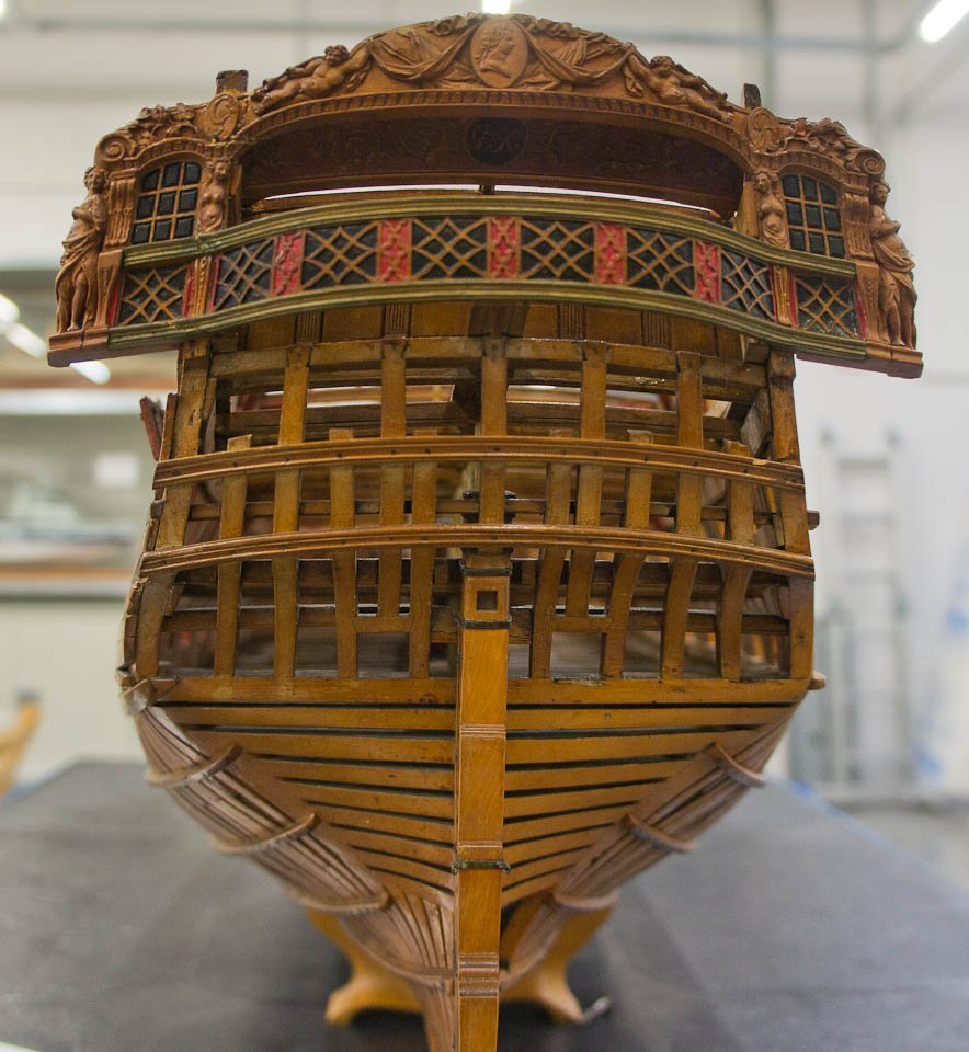
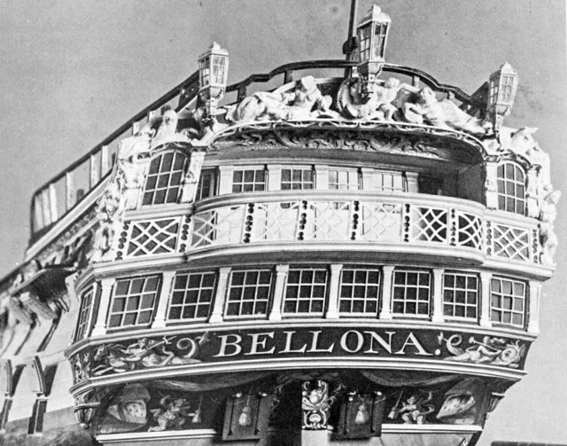
But as I get up to the top of the stern, I have to make a final decision about which version of the Bellona I will build. I never did like the later 1780s remodel as shown in the second model, with its awkward railing on the sides of the poop deck:
SECOND MODEL

I much prefer the original design as seen in the original model below:
ORIGINAL MODEL
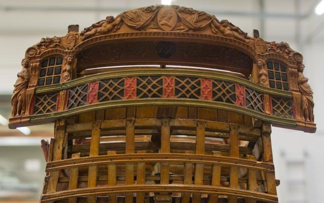
So to be consistent with the original design, I have decided to do all of the ornament as in the original design, which I also think is less fussy than in the second model.
And to be consistent, I should probably construct the serpentine curve to the balcony in the original model, as opposed to the balcony with the sharp break in the second model. Although, the original drawings show a balcony with a sharp break:

Hard to know how to get back to original...
A question for those of you with extensive libraries of photos; notice that in the second model, the decoration in the railing is pierced, whereas in the original model, it is a solid railing with the decoration applied to a solid face. Do you think this was an expediency for the model maker, or are there examples of other ships with similar decoration on a solid rail? I notice in the original model that the quarter gallery windows under the arches are carved from the solid, which I don't think would have been in the actual ship. This suggests that the railing might also be an expediency. It sure would be easier to build if it were solid and not pierced....
Mark
-
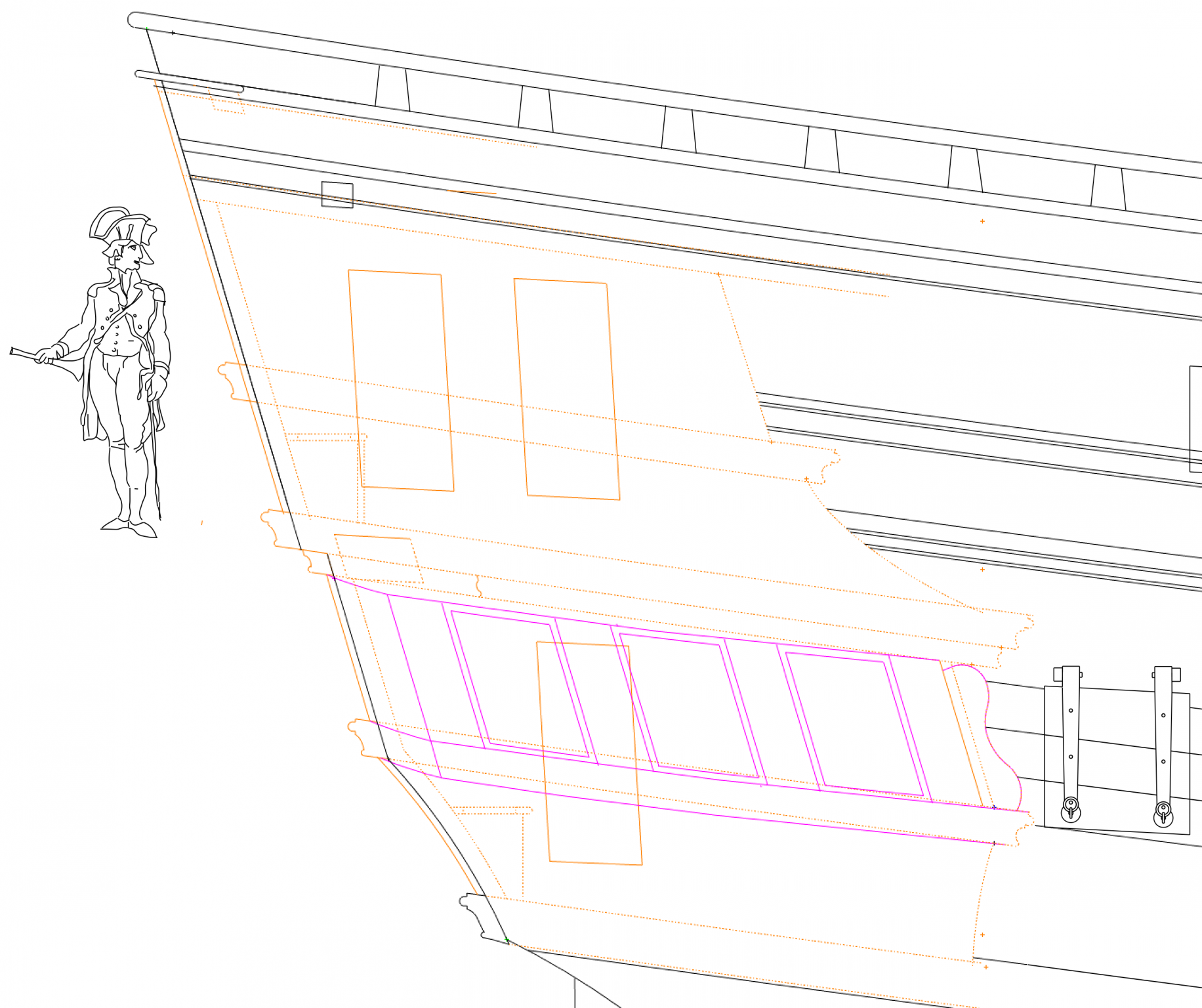
So a little paper shows a lot! My CAD drawing was accurate, and model reveals that if the top and bottom of the windows are parallel but offset, the top one has to pull out further from the hull in order for the lower one to just hit the side. In other words, there is a gap at the top one, as seen here:
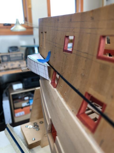
Looking back at the second Bellona model, it is clear that this is made up somehow by what druxey called the canting livre, as seen here:
I see I need to lay out the window muntins from the lower sill, and leave the gap at the head. Then it is filled by that little triangle. Funny, I never knew what those were for, until I tried to lay out the quarter galleries!
Mark
- GrandpaPhil, Stuntflyer, druxey and 4 others
-
7
-
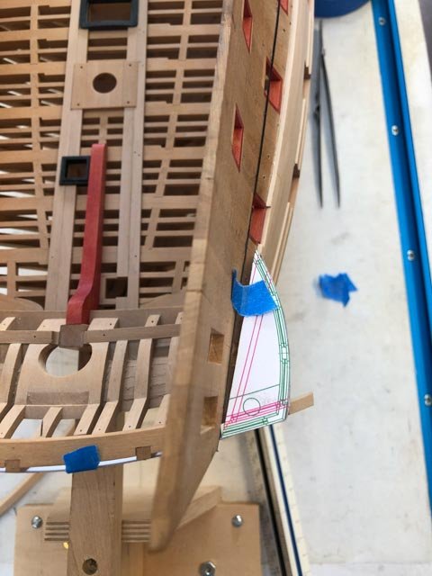
Thanks, druxey, so it is like on a cylinder not a cone. I put tracing paper over the Steel Plate VII, and sure enough, the upper and lower curves are the same, just shifted.
On paper, this makes my lower cill too short to accommodate the foremost munition; so it must be a drafting error somewhere. I will try mocking up some cardboard parts on the actual model and see what is going on here.
- druxey, paulsutcliffe and mtaylor
-
3
-
Mark, that is a very interesting cross section, for those of us focused on English construction. The tumblehome actually turns back out topside.
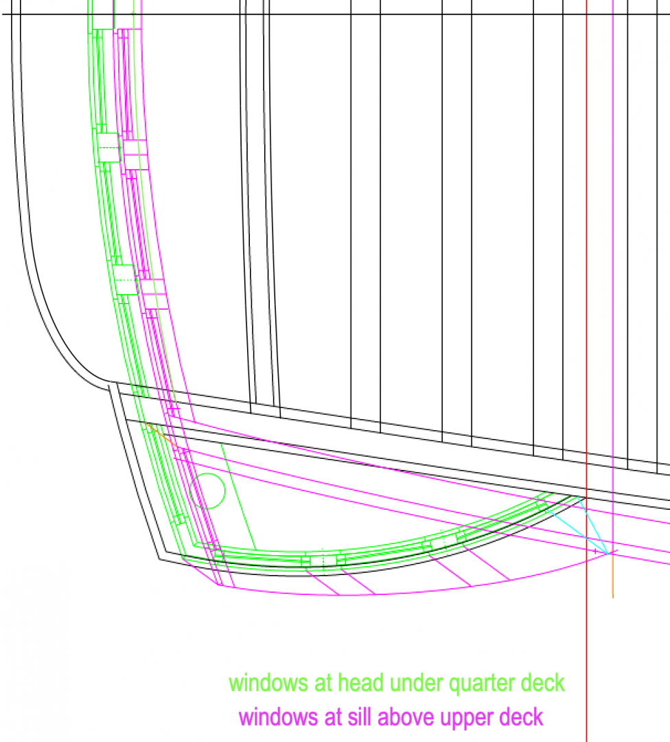
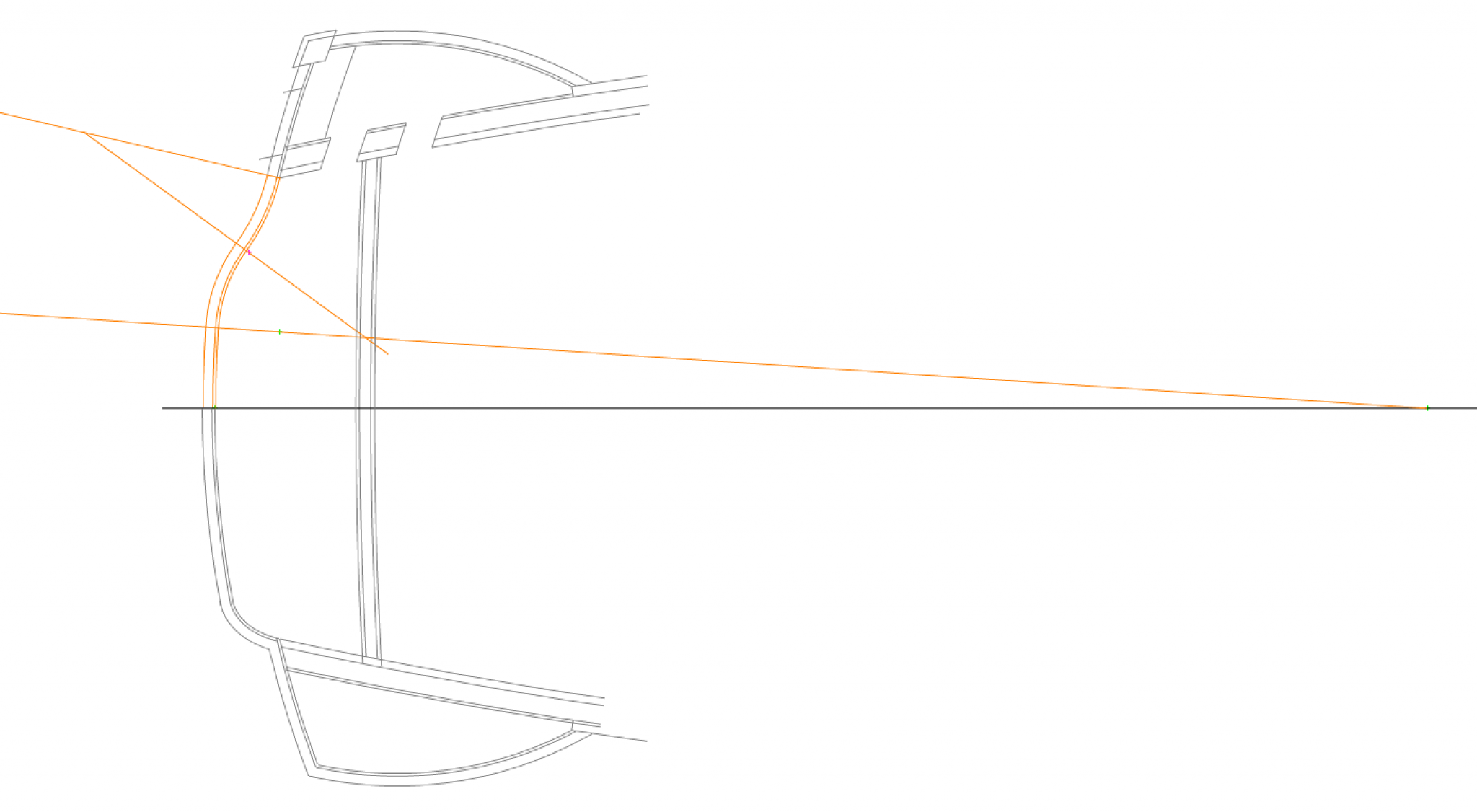
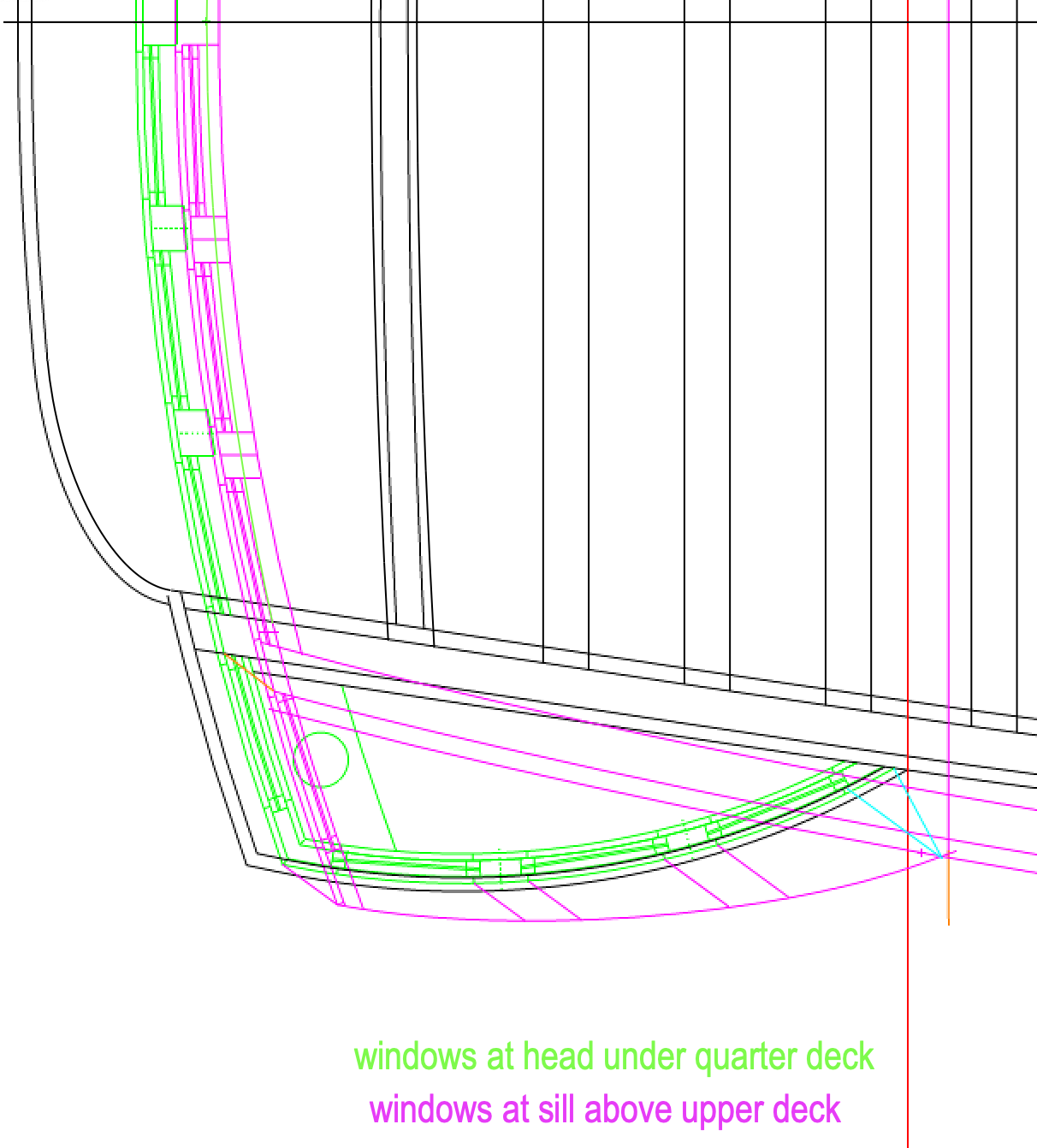
Well, I have spent a very interesting day working out the geometry of the quarter galleries. The green below is the head of the windows just under the quarter deck, while the purple is the sill of the same window, up from the upper deck. According to Steel, the lines of the muntins between the windows in plan should be parallel, in order to ensure no winding in the window face (which would make it impossible to fit flat glass). However, when I get to the muntin at the fore end of the quarter gallery, the line is not parallel to the others. It should be the leftmost blue line which is parallel to the others, and it turns out to be the rightmost blue line, which is based on the original sheer showing where the gallery hits the side of the hull at each of these levels. So something is not lining up right.
Did I read somewhere that the windows on the quarter gallery would have to be like the side of a cylinder, as opposed to the side of a cone, in order to ensure it is out of winding? Is that what the parallel lines insisted upon by Steel are meant to ensure?
Maybe a fresh look in the morning!
Mark


HMS Bellona 1760 by SJSoane - Scale 1:64 - English 74-gun - as designed
in - Build logs for subjects built 1751 - 1800
Posted
Thanks so much, Jason.
I am using TurboCad Deluxe for the Mac, a relatively cheap CAD program, about $150, as opposed to thousands for AutoCad.
It is a little buggy sometimes, but it is getting the job done. I started out drafting this project many years ago by hand, and I have become a convert to CAD as I started to refine the drawings I needed for the model. It is so easy to try things and change, duplicate and mirror, put things on layers to see how they relate to each other.
Mark