


SJSoane
-
Posts
1,621 -
Joined
-
Last visited
Content Type
Profiles
Forums
Gallery
Events
Posts posted by SJSoane
-
-
Hi everyone,
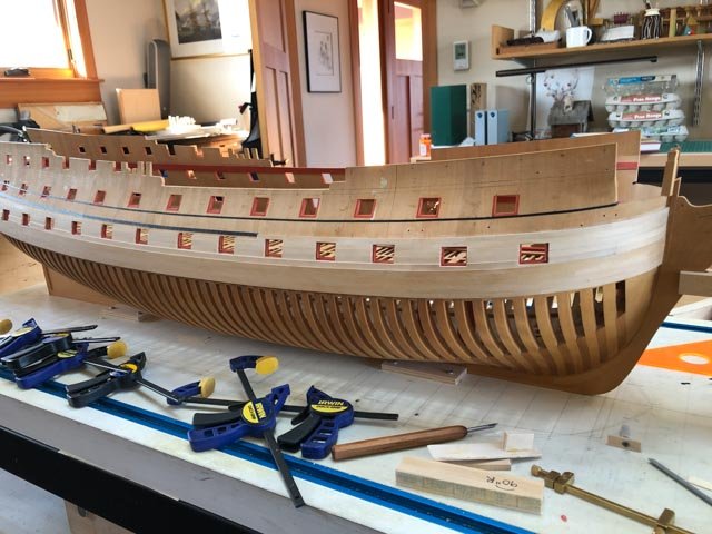
Here is an update, mainly to say that I am still around. I am proceeding aft with the uppermost strake of 4" plank below the channel wales.
After some recent family health scares, it is probably a good idea to spend some more time in the shop and think about positive things!
Mark
-
-
Hi Siggi,
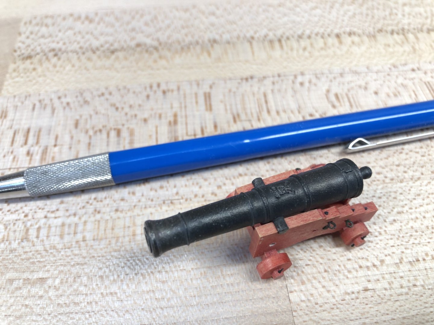
The GR insignia cast very well. You don't see it right away, but this would have been true for the full size cannon as well. It is there for the viewer to discover!
The image below is my 32 pound cannon, at 3/16" = 1'-0".
Mark
- Edwardkenway, dvm27, FriedClams and 14 others
-
 17
17
-
Siggi, that is a beautiful turning, very nicely and accurately detailed.
I read that pewter is tin plus copper and antinomy. The first batch of pewter I used required too much heat to melt, and it destroyed my rubber molds very quickly. The second batch melted at a much lower temperature. The difference was in the proportion of the different elements, but I don't remember what.
Mark
- Vladimir_Wairoa, FriedClams, Siggi52 and 1 other
-
4
-
-
-
Hi druxey,
I tried the thread and dilute glue, but I kept disturbing it as I was clamping, fitting, etc. around it. I found that the tape was more durable, particularly over the many months it takes me to get anything done. Also, I wanted to scribe a line on the hull for future reference, but the thread moved between glue locations. I did use a technique from the thread and glue, in that I fine-tuned the location of the tape once it was on the hull by gently pushing sections of it up or down. I used an old graphic artist burnishing tool for this purpose.
OK, I'll try some ways of laying out the deck planks, and see what happens. If I get anything useful, I'll post it!
Best wishes,
Mark
- Hubac's Historian, druxey and mtaylor
-
3
-
I have not been showing planking recently, because it is now just one plank after another until I finish the last strake of 4" planking below the channel wales.
However, I thought it might be of interest to show some things I have learned while planking.
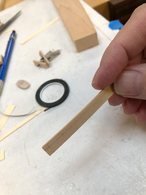
First, I had a challenge scribing the upper edge of a spiled plank, particularly on a curved planks as at the bow. I tried using a manila filing folder template, but it was too irregular. I tried using a flexible curve, but it would not bend in two directions. So then I hit on the idea that works well for me. I plot the points through which the curve must flow, and then I use artist's tape to fit a smooth line to the points. This is the same as I did on the hull itself.
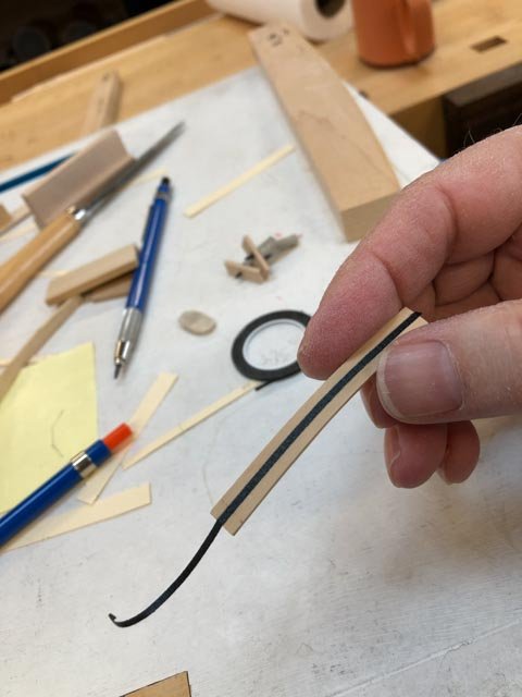
Then it is an easy thing to draw a sharp pencil line along the tape.
The uppermost 4" plank at the curve of the bow was the most difficult to fit so far. It curves around the bow, it curves up for the sheer, and it twists from vertical at the bow to sloping inward further aft because of the tumblehome. This piece took me almost four hours to fit.
Here is a dry fit to test the fairness of the mating edges:
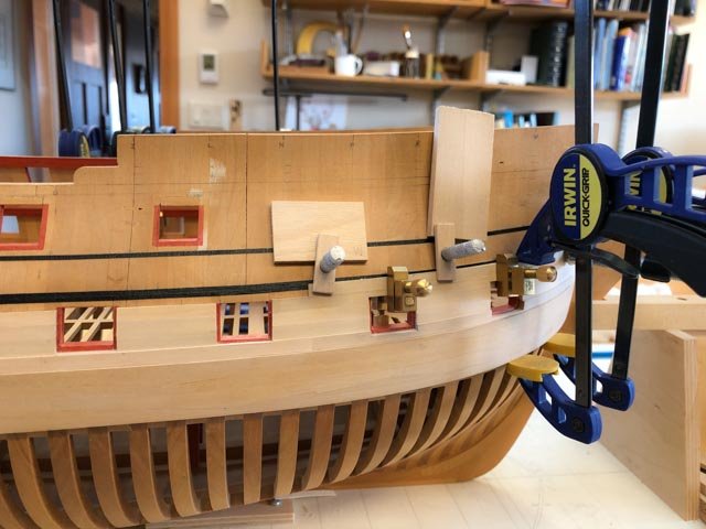
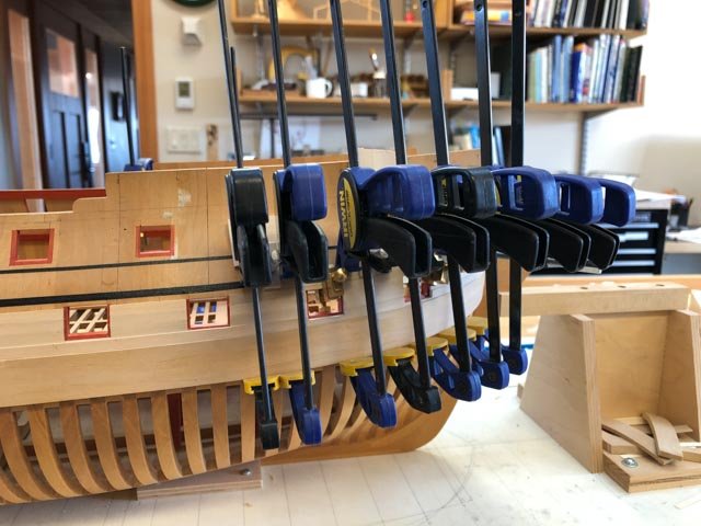
Here is the piece clamped up:
And here is the result before final sanding:
You will see that I have a double band of black artist tape at the lower edge of the channel wales. When I first put it on, I put the upper edge of the tape against the plotted points on the hull. And when I finally got to the upper plank, I realized that the tape was now in the way of the plank! So I put another line of tape above, and I am peeling off the lower one as I fit the planks. Next time I put on tape for lines on the hull, the tape will go above the line!
Mark
- dvm27, druxey, KARAVOKIRIS and 14 others
-
17
-
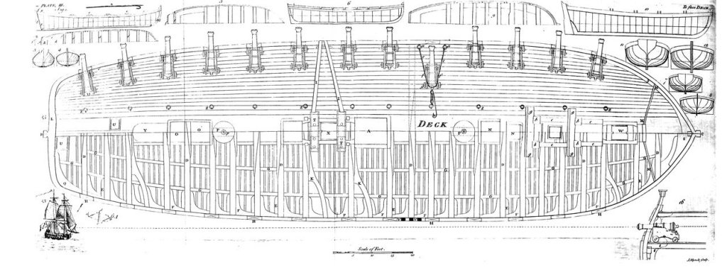
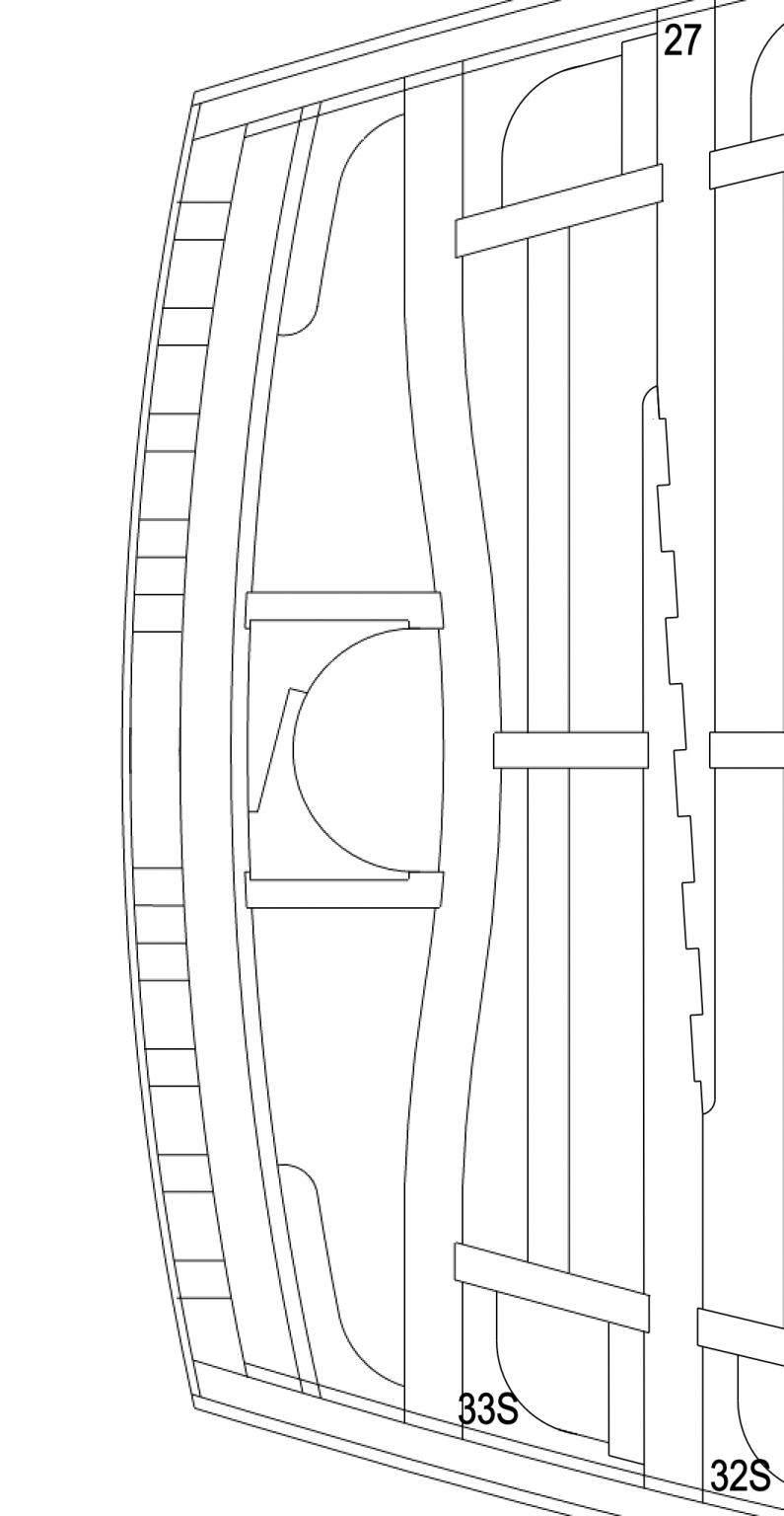
Waiting for more glue to dry on planking, I started thinking again about the gundeck planking. I don't seem to find any guidance on how to lay out deck planking that tapers to bow and stern (as seen in Falconer's gundeck below). I can only think to draw a rectangular box around the deck, width equal to the width of the deck at its widest point, and then reduce the width of the ends by some ratio like 7/10 of the full width. Next, divide center and ends by the number of planks, and connect the dots with arcs of circles.
Can anyone direct me to a discussion of how to do this?
Mark
-
-
Something a little more like this. This is about as wide as the mast partners. And a little wider seat on the rabbet.
-
Marc, I recently built a plastic kit of an LCVP landing craft for my father, his assignment in WWII. Not so much easier than wood--easier to cut, harder to finish! I admire your work in this medium.
druxey, here is another idea for the chock around the rudder head at the upper deck. I am thinking it might be like a mast or capstan partners, with a lip set down onto a rabbet in the carlings, and a large lapping joint between the two halves of the chock. I think the lower surface of this chock would also have to fay down onto the upper surface of the lower counter below, to keep water out through the entire height of the hole through the hull for the rudder.
Mark

-
Marc, I will trade that compliment right back to you. I think you are working on far more complex forms and details than I am!
Mark
-
Thanks so much, druxey. I can't make the last one, the Dorsetshire, quite line up with my rudder head/transom relationship. But the first two, with a full curved beam, could work. These perhaps makes more sense than the one I show, which would be a funny piece of wood to find out in the woods....🙂
It is interesting to think what keeps that curved beam from rolling over on its axis, except all the horizontal carlings and decking resisting the lateral movement it would need to roll. Not an ideal structure, but it obviously worked for them back then.
Mark
- druxey, mtaylor and Hubac's Historian
-
3
-
-
Thanks, GrandpaPhil, It is always a good reminder to look for tools and materials wherever they might be found.
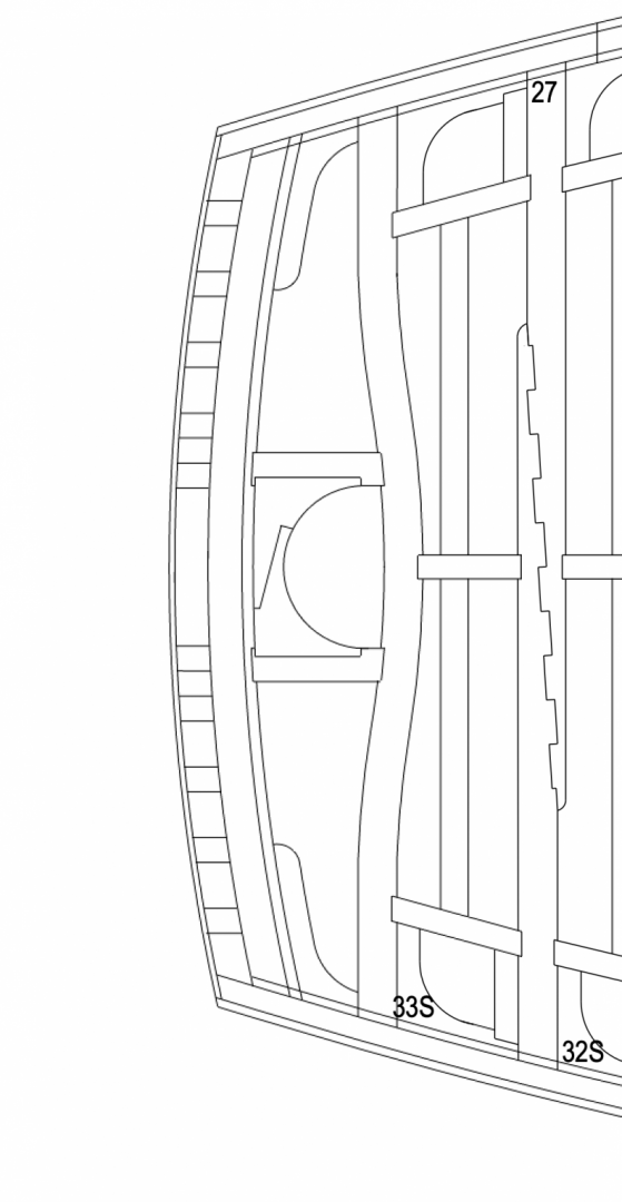
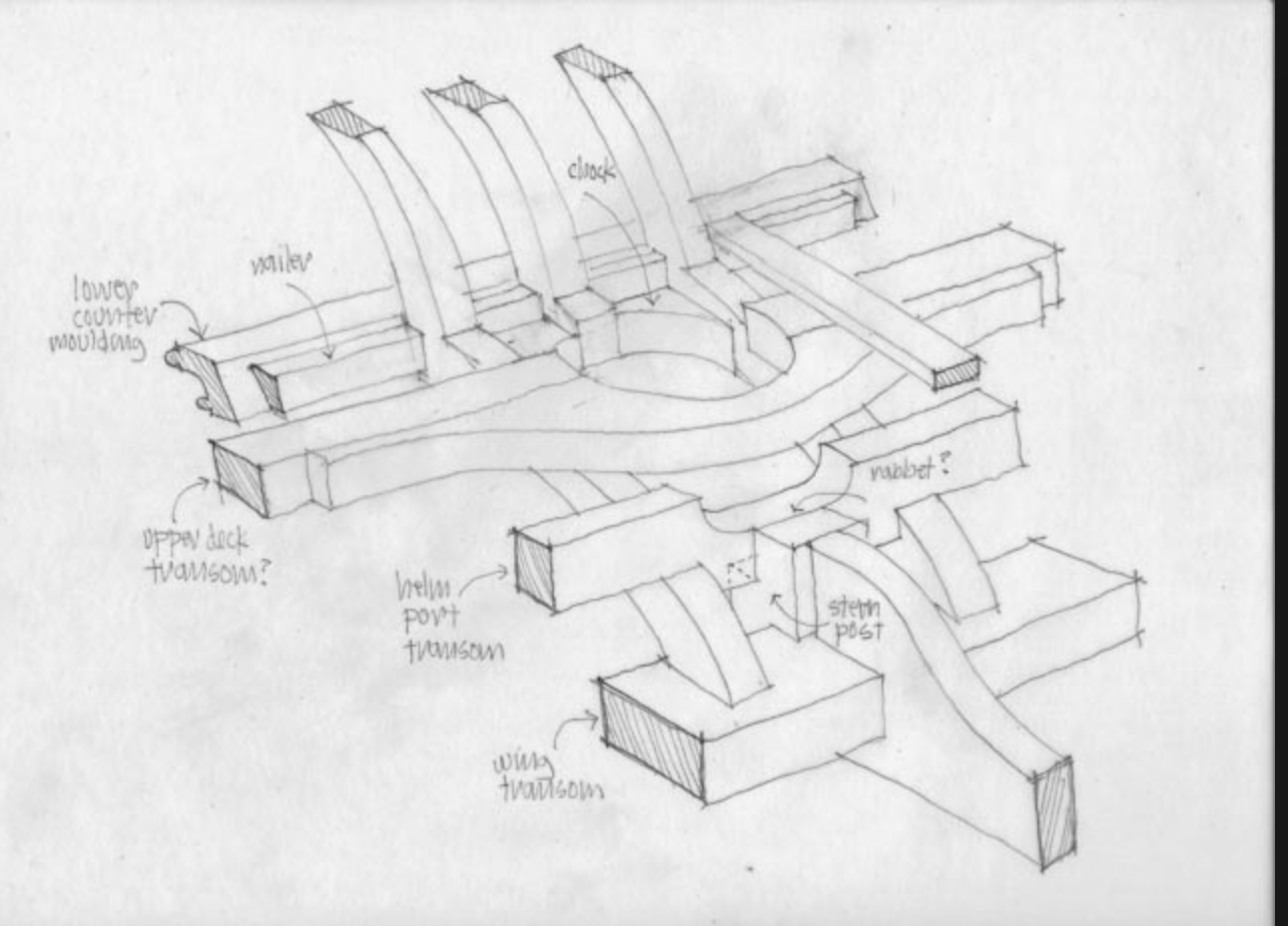
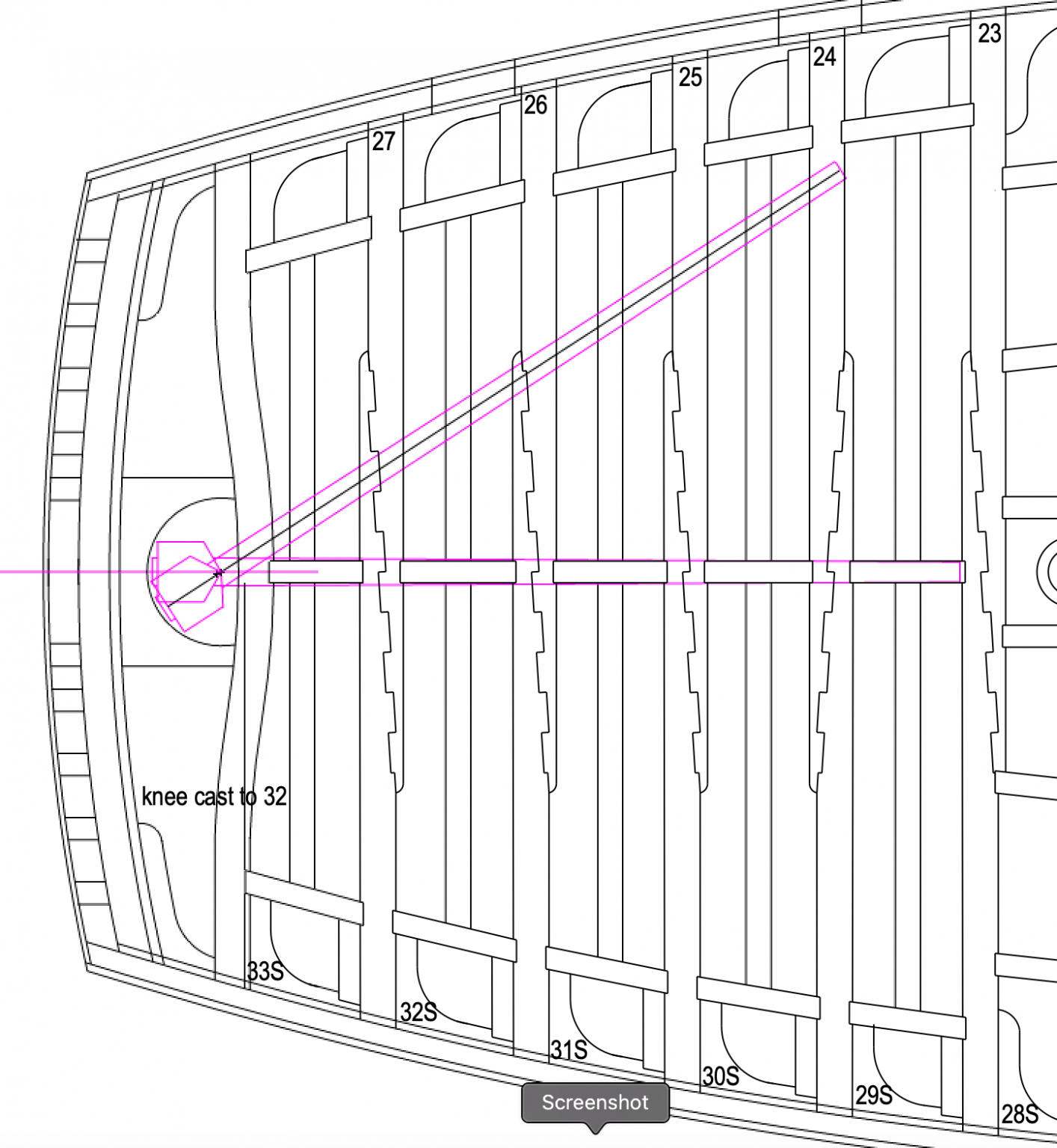
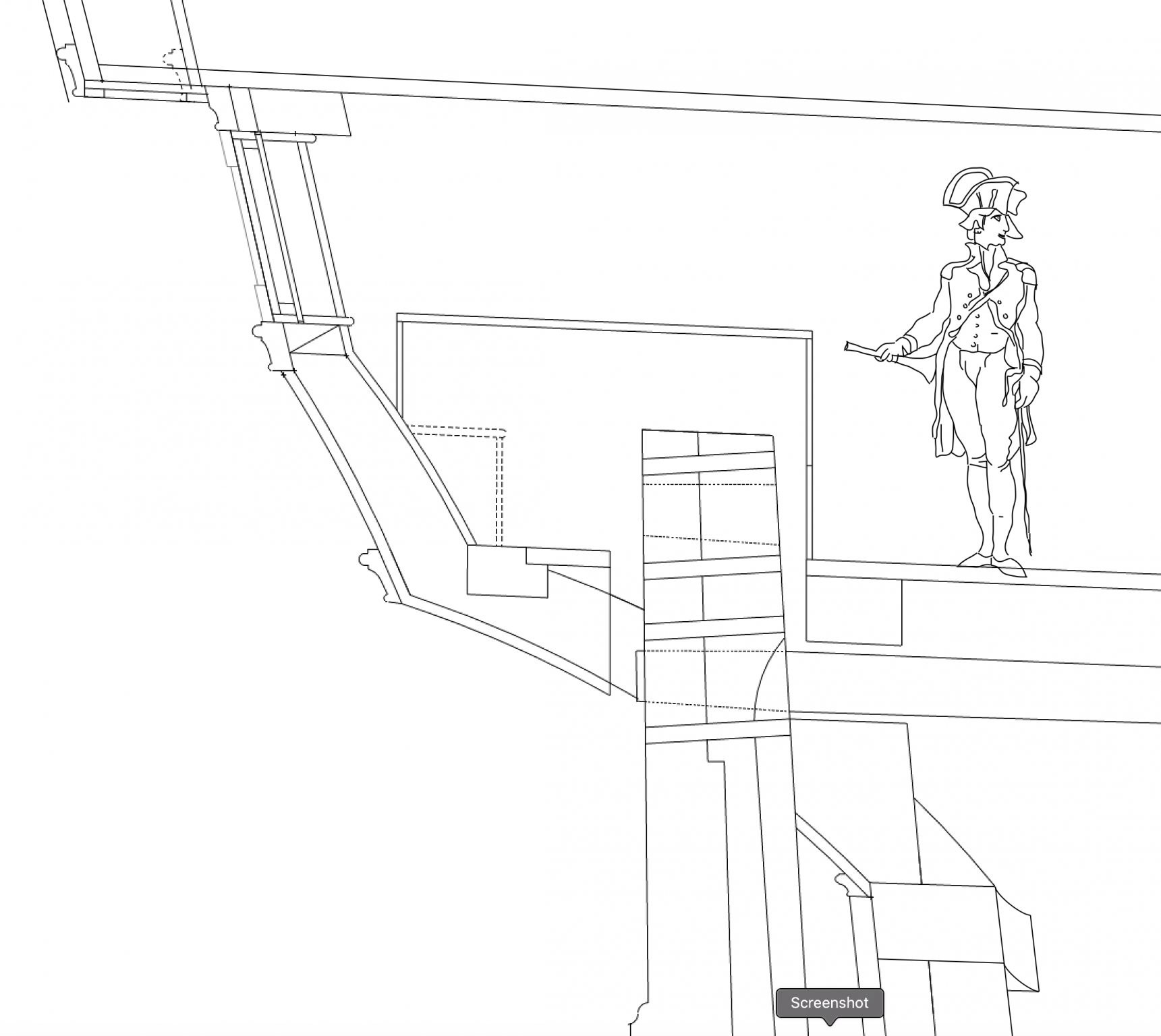
While waiting for the glue to dry on the foremost of the top 4" strake under the channel wales, I have looked more closely at the detail around the rudder head and window into the upper deck. I have finally figured out where the transom goes, and there is likely a curved beam just in front of the rudder head, with a thickened piece around the rudder head for landing planks between the two:


The drawing I made many years ago did not quite get it right (see below). It really helps to see the actual structure built so far, and envision what has to happen to make it all work.
Best wishes,
Mark
-
Hi Marc, just caught up with your build. Truly remarkable scholarship and craftsmanship. I would never have the courage to take on a stern that complex, you are a role model for us all.
Mark
- Hubac's Historian, druxey and EJ_L
-
3
-
Fun! keep them coming!
Mark
- mtaylor, AON and thibaultron
-
3
-
-
Thanks, Siggi, this is very helpful. druxey has also explained to me how I might use mica for the glass, and this would certainly work better in the sense of much thinner windows.
Here is what that the detail would look like:
I will pick up some mica and see how this might work.
Mark
- mtaylor, druxey and Beef Wellington
-
3
-
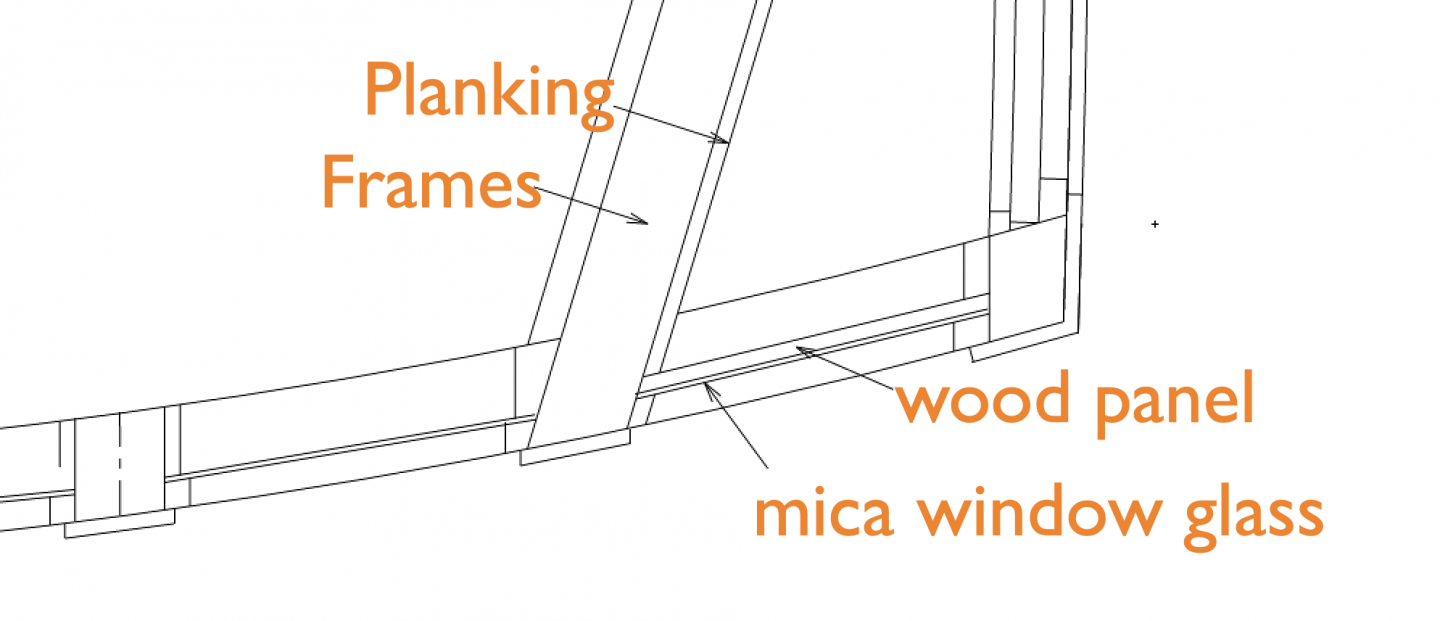
Thanks, Siggi,
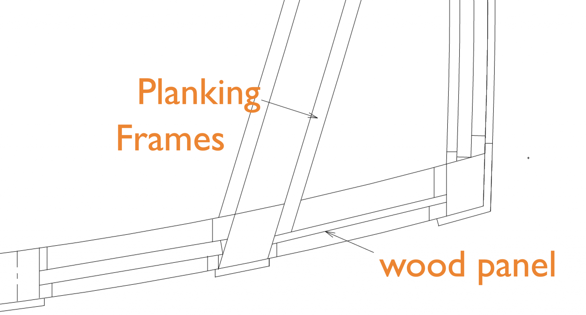
I just drew up two different versions of the window, one with glass and a wood panel, the other with just the wood panel.
Here is with the glass:
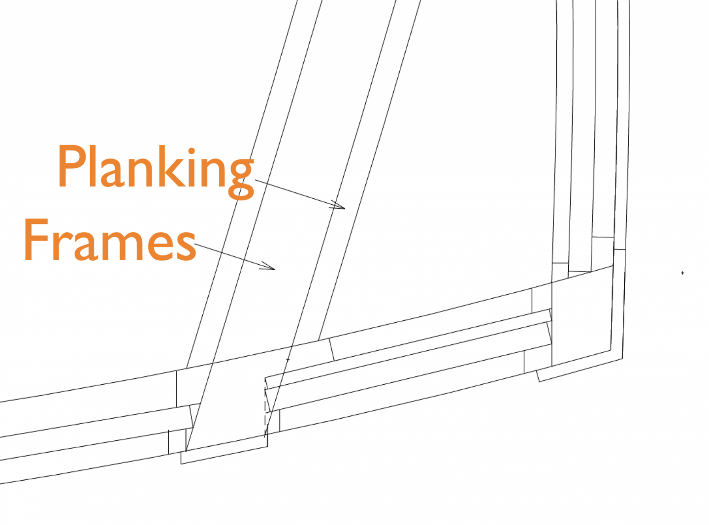
And here is with only a wood panel:

The construction certainly is simplified with just the wood panel, particularly since my glass sheets in the model are thicker than they should be to scale. In the examples you have seen, was the black paint glossy, or Matt? I can try some experiments with glass, wood and paint to see what makes sense for the model.
Mark
- mtaylor and GrandpaPhil
-
2
-
Hi druxey,
Just saw your post after I posted mine. Thanks for the observation of the actual models. I am likely to continue with that tradition, because I think it would just look better! See, now I am thinking like an 18th century shipwright!
Mark
- paulsutcliffe, druxey and mtaylor
-
3
-
Hi Gaetan and Jason,
Thanks, this is additional confirmation for what I now see would have been a clearly common practice.
I remember reading about false windows on buildings in England, so there would have been a cultural precedent.
Interesting in the photo Jason provided above that the fore and aft windows were also false, except for what appears to be one upper sash of one window. The captain must have desired exceptional privacy when docked!
Good point about whether there was glass on the outside of the false window paneling. Maybe that was just a modeler's conceit, because it would have been expensive and vulnerable to provide glass for no functional purpose in the real ship. But then there were a lot of expensive, vulnerable and functionally useless things on these ships like the carvings and friezes. Maybe aesthetics counted far more than we assume today.
Mark
- Beef Wellington, druxey and mtaylor
-
3
-
Hi druxey,
Ahah, that link to the photos of the Bellona model at the NMM clearly shows in the black and white photo that the end windows are blind. I never noticed that before. Do you recall if you modeled the wood paneling right up flush to the glass, or is there a gap between glass and paneling?
Mark
- paulsutcliffe and mtaylor
-
2


HMS Bellona 1760 by SJSoane - Scale 1:64 - English 74-gun - as designed
in - Build logs for subjects built 1751 - 1800
Posted
Thanks so much, Marc. We had a scare with the virus with a relative in Denver, where the entire city is now locked down. Relative OK, now quarantined. But you have it way worse in New York City, Marc; stay safe!
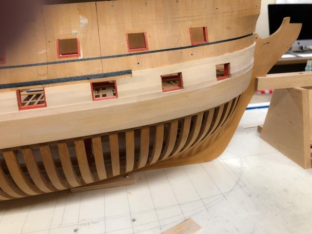
Slowly moving along with the top strake of 4" plank. Just for fun, and for a break while waiting for glue to dry, I temporarily clamped a cheek on at the bow, and sat upon it a rough blank for the hawse liner. Still to be shaped, but it begins to show the lines relative to the planking. It is interesting to see how the cut down of the hull at the forecastle is not parallel to the outboard planking. It slopes down rather more towards the bow. I double checked the drawing, and this appears to be so the little deck at the bow is aligned more with the sheer of the upper deck, which it sits just above. This visual anomaly will pretty much be obscured by all of the head work later.
Mark