


SJSoane
-
Posts
1,641 -
Joined
-
Last visited
Content Type
Profiles
Forums
Gallery
Events
Posts posted by SJSoane
-
-
Thanks so much, druxey and Michael. I return the compliment to both of you, because you have both been inspirations to me over the years, with your good advice and your own examples of the highest levels of craftsmanship to which I still aspire!
Mark
- AON, daHeld73, Hubac's Historian and 3 others
-
 6
6
-
Snow just fell for the first time, one of the earliest times on record. News reports are predicting an "historic storm" in Northwest Montana. Which means, more time in the shop!
I just completed the black strake on the starboard side. Because the sheer line rises faster than the gundeck and therefore the ports, the black strake eventually crossed right through gunports, leaving only short pieces between ports.
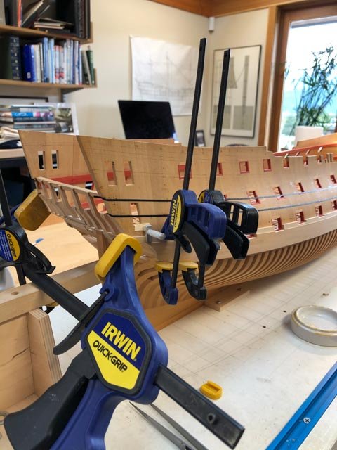
My gunport stop jigs worked well here. Wedged into adjacent ports, this gave me the angle to sand on the Byrnes disk sander at both ends, and then I just sanded lightly at one end until the plank slid exactly into place.
The aftmost plank had a bit of a twist, so needed bedding down with a larger clamp across the stern.
The difference in thicknesses between the main wale and the black strake has left a gratifyingly consistent sliver of light, showing that they are parallel and not wavy relative to each other. Hopefully, the 4" plank on top of the black strake will form an equally even sliver of light.
Now if only I don't have to snowplow for too long tomorrow morning, I will start on the port side.
By the way, I received an important insight into animal behavior today. The ship's cat sleeps all day, except for the exact moments when I apply glue to something and need to work quickly without interruption to apply clamps. These are the exact moments when the cat wakes up and demands food. How do they know?🙂
Best wishes,
Mark
-
A few more hours in the shop sneaked in. Installing the black strake is going better than I expected. Careful preparation with a sanding thicknesser on the wales has so far ensured that the highlight of light at the top of the wale is pretty even along the face of the black strake. That was my biggest concern, a wavy edge between the two. So far, so good....
Mark
-
Greg, I understand old Hollywood actresses always had their photos taken with a softening filter, to ease away the imperfections. You would never see the imperfections in real life, but in artificially close up photos, the imperfections showed. I wonder if ultra close up photos of the old Admiralty models would show greater imperfections than we see with the naked eye. If so, I think the model ship building community should use softening filters for all of our ultra close up photos. Fair is fair...😀
Mark
- mtaylor, GrandpaPhil, Canute and 3 others
-
6
-
-
Hi druxey, Thanks, this confirms my thought that the widening of a wale up or down would be thinned to the adjacent planking, to maintain the smooth run of the wale edge.
This becomes especially interesting in the Bellona, because both wales are significantly cut into by ports, given the greater sheer in the wales relative to the sheer of the decks. The wales and ports are interacting quite a bit.
Nice view of your project, by the way!
Mark
-
Thanks, druxey, Marc and Vane. I think this is probably more common that I would have thought, to live for the process more than the finished product! And also, projects that last decades...
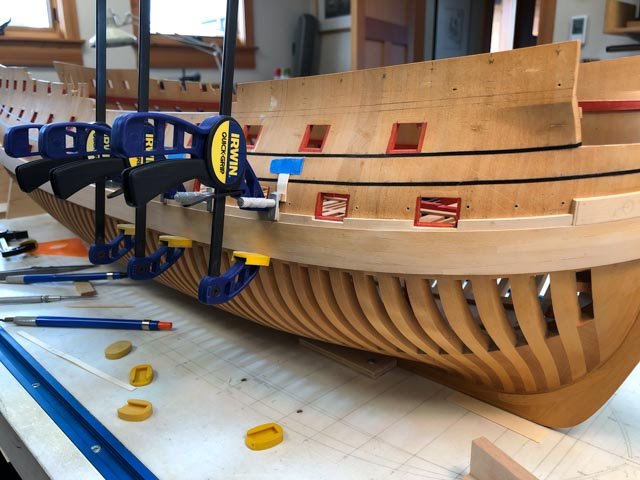
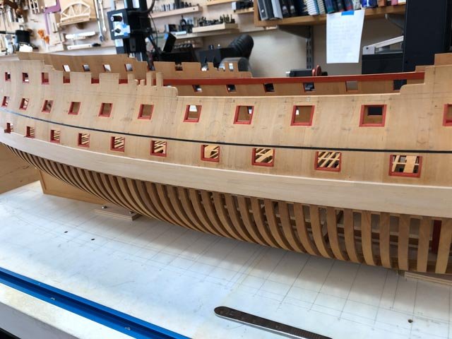
In between numerous summer visitors, I have slowly been working on the black strake above the main wale.
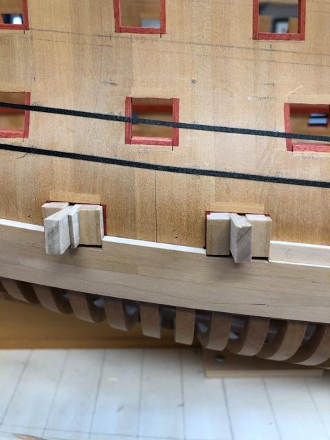
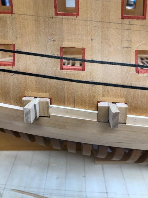
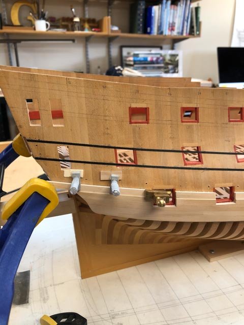
A few points of possible interest in the photo below:
1. I finally settled on the black artist tape for locating the run of planking. I kept dislodging the string when messing with measuring the plank widths, and fitting the pieces. The tape allowed me to draw a firm and continuous pencil line on the hull, which enables me to move the tape back to the right position when it dislodges. On my solid hull, the tape pulls smoothly for developing a fair line and gives me an accurate line at any point on the hull; for plank on bulkheads, or an accurately framed model with spaces between the frames, I imagine the string will work equally effectively in marking at intervals on the frame. Each to his or her own, I imagine.
2. See the little wedge of planking under the first porthole. In principle, the wale below should have raised up to the edge of the port to avoid this skinny wedge. But after looking at numerous Admiralty framed models, I have seen not a single example of the wales--main or channel-- raised up or down to portholes to avoid this problem. I can only imagine that the wale did raise up or down, but it was thinned down to the adjacent planking at these points so as not to interrupt the flow of the wales. The end result visually is a thin wedge above or below ports. That is my story and I am sticking to it!
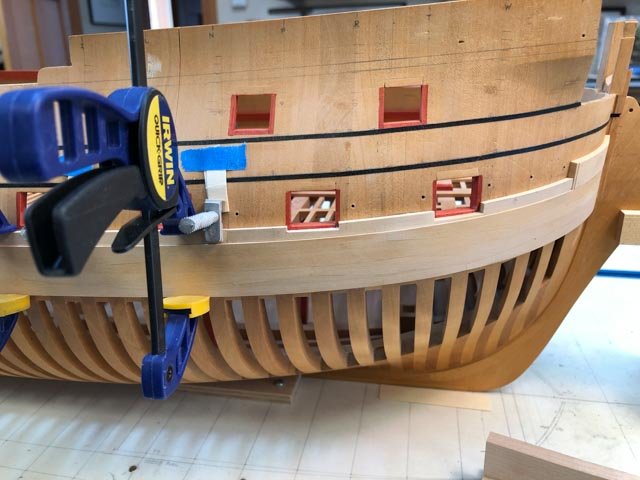
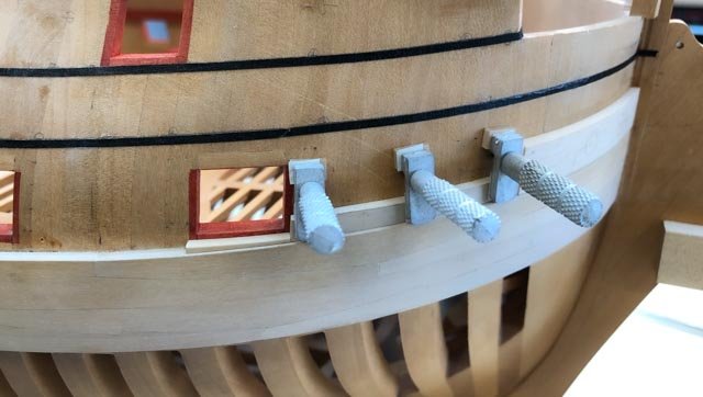
3. The offset of just 1 ½" in thickness between the main wale and the black strake means that there is a very fine reveal between the two. The slightest variation in thickness for either, or an inadequately clamped glue job, will show as a wavy, varying width in the reveal. To help ensure absolutely even clamping, I turned to some planking clamps I bought from Micro-Mark many years ago. They screw into the hull, and closely spaced they really pull the black strake evenly to the hull. The hole will obviously be covered up by later planking higher up. I did have to modify them, with a card pad on the clamping side, and a thicknesser above the screw to ensure that clamp grabbed evenly all the way across the plank.
4. I may have to make up a special sanding block to sand both the main wale and the black strake at the same time, ensuring a constant reveal between the two. We will see how close it is before I resort to this.
Best wishes,
Mark
- GrandpaPhil, JOUFF, Stuntflyer and 7 others
-
10
-
-
-
Hi Vane and Marc,
Thanks so much for your kind comments.
I looked up in my log book, and reminded myself that I decided to build an Admiralty model while I was visiting the Maritime Museum in London in 1988, choosing the Bellona because I like the look of mid 18th century ships the best, and I was able to obtain Lavery's book on the Bellona. I spent the next 10 years--off and on--redrawing the ship from ¼" to 3/16" with the limited resources I had at the time, and began construction June 5, 1998. And since that time, I have been able to work on it off and on, sometimes putting it away for months or a year at a time. So I started drawing 31 years ago, and constructing 21 years ago, with gaps in between.
I am not sure if I am unusual in this regard, but I would have to acknowledge at this point that I am only going to build one ship in my lifetime (other than a wood kit of a schooner I built when I was 16). I think I am about 2/3rds done, and at my current rate of progress I am likely going to need another 10-15 years.
This project obviously became much more than just building a model of the Bellona. I decided early on that I wanted to craft my model as well as the Admiralty models I saw in London, even though I had no particular skill in this when I started. So building the model also involved learning through doing, and thinking hard about how to accomplish something at a higher level of skill than I had at any given time. This meant it went very, very slowly as I built jigs or practiced skills while tackling a new aspect of the build. And throwing away a lot of efforts that didn't meet my standard.
Also, when I started, I had access to very little information about how these ships were constructed. So throughout the years, as more information became available--particularly thanks to this website--I have had to go back and rework things already made, or redraw things not yet made, to accomplish a model as close to the original Admiralty models as possible.
At the risk of sounding like a cliché, this project really has become more about the journey than the end. I enjoy the learning and puzzle-solving as much as the construction, and working away in the shop is almost like a meditation period--a focus on a familiar yet always challenging project. I can't quite imagine what life would be like without the Bellona to work on. I will have to hold off gluing on the last part until the very end!
Mark
- egkb, John Cheevers, GrandpaPhil and 7 others
-
10
-
-
As we start to approach the end of summer, lots of things get in the way of working on the ship. I am almost looking forward to winter....
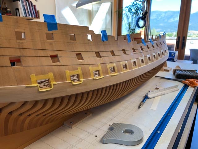
I did manage to stain all of the port sides and cills. I had to remove the string showing the run of the planking to do so, and just for fun, tried showing the run of planking with artist's 1/16" tape, as shown in Chuck's planking tutorial.
It seems to work well either way, with some advantages and disadvantages on my solid hull. The string required gluing on, leaving little lumps at the glue spots, and it is harder initially to pull it into a fair line; but it is easier to push and pull it into place for a fair line before the glue sets. The artist's tape is easier to pull into an almost fair line, but harder to move for adjustments because the adhesive sticks immediately. I had to run a scalpel along the tape in places to release the adhesive, pull into a fairer line, and then press down.
My hull frame is starting to look a little ratty after all of these years of banging around, and I look forward to covering this up with some nice clean planking!
Mark

- archjofo, tlevine, Captain Poison and 8 others
-
11
-
-
I finally got things organized enough to stain the port sides and cills.
This stain at the edges and top will be overlapped by planking, so it was not essential to keep a neat edge. But I thought that I might be staring at this for some time to come, since I am so slow in construction, and so I decided it would help my morale if it looked neat at this point.
I therefore masked the edges with Tamiyo tape, leaving a little beyond the 3" that will be revealed by the planks. I also blocked out with paper, just in case I got messy.
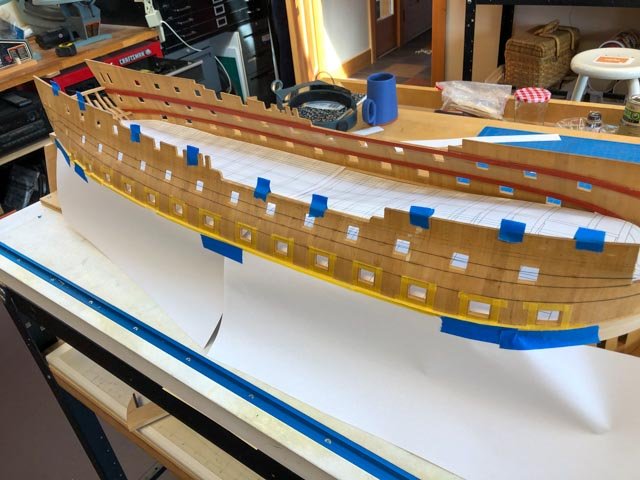
And then I used my normal red stain, wiping on with a cloth. Messing around with this dislodged my thread planking lines, making this look all ahoo. I need to clean this up before FINALLY beginning planking...
Mark
- Stuntflyer, mcpwilk, tlevine and 18 others
-
21
-
gorgeous project and carving!
Mark
- giampieroricci and mtaylor
-
2
-
thank you druxey, Greg, Mike and Jason for these very helpful ideas on this challenging detail.
I think I am almost there; the final test is sanding sealer on the ends of the planks, then paint with the Floquil before installing the planks. I am not sure how my rub on poly finish will interact with the sanding sealer, so I need to check that out before I run into problems with the final finish on the outside of the planks.
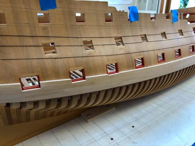
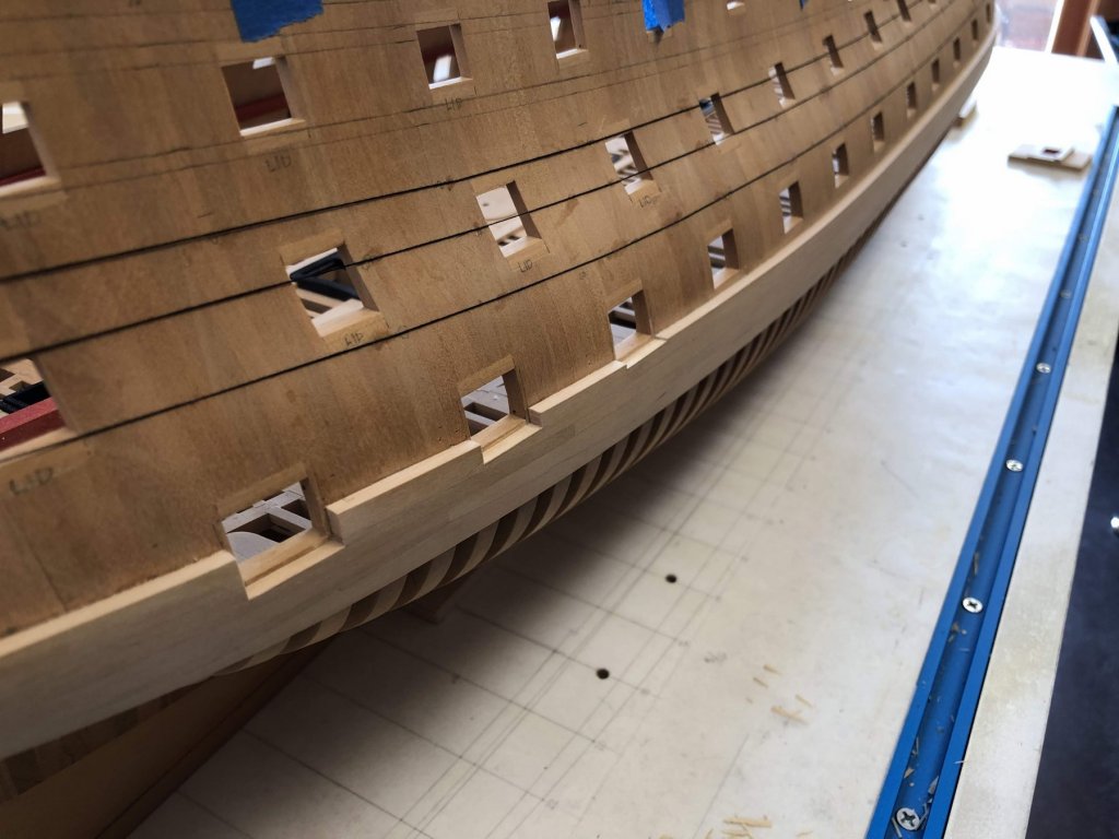
I finally took on a task that I have been avoiding for some time, trimming down the wales at the three aft-most ports to reveal the 3" port stops. It was very tedious, chopping into the wale material without damaging the face of the frames to which they had been glued. In hindsight, I might have trimmed these before installing, although the challenges of bending and clamping these pieces probably would have induced errors and shifted the cut line anyway.
One side done, the other awaiting a time when I feel like tedious work...
Mark
-
hi druxey,
That sounds like a great idea. I realize that I can paint the ends of the planks before installing, which should help with access to this difficult edge. And sanding sealer would be easy to apply at this point. What do you recommend for sanding sealer, with enamel paint coming over it?
Mark
- daHeld73, Hubac's Historian, mtaylor and 1 other
-
4
-
Hi Jason, thanks so much. I see you did a very nice paint job on your HMS Snake; do you remember what paint you used, and how you did the edges of the planks? I am still open to ideas!
Mark
-
I discovered this morning that I had two old jars of Caboose Red, one was PolyScale acrylic, the other Floquil enamel. The PolyScale was too red, bu the Floquil was perfect. I tried 100% paint, and then diluted 50-50 with thinner. The diluted looked a little more like the stain, and this is what I tried on my mockup. But the paint ran a bit. I did manage to scrape and sand away the overflow, so it did not seem to get into the deeper grains as the stain does. So, I might be in business here. I may try undiluted paint, which I imagine will run less, but will be brighter next to the stain.
Mark
-
Beautiful CAD drawings, and beautiful craftsmanship on the stem so far!
Did you do the sketch drawing of the crew?
Mark
- mtaylor and Oliver1973
-
2
-
hi druxey,
Yes, I will try that. It looks good!
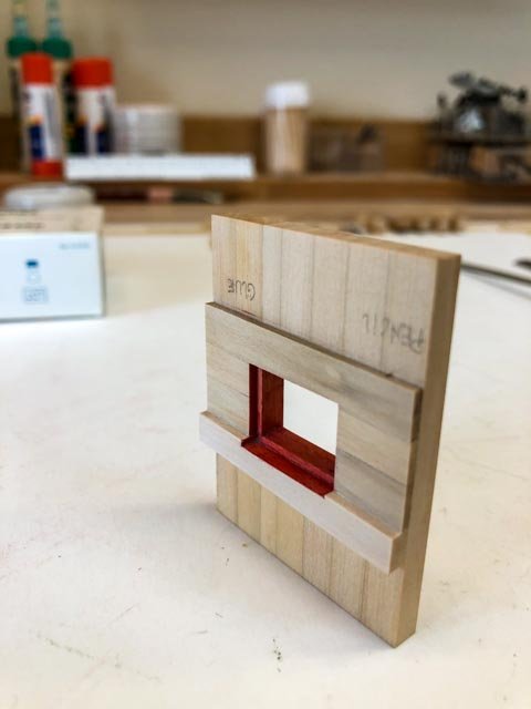
I had a good day building a mock up of the ports, testing some construction and painting ideas.
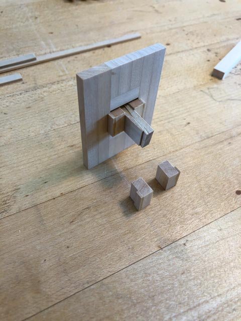
I made a little jig, with rabbets the size of the port stop, for drawing the stop edge on the frames, then using them to scribe the edge of the plank, and finally to align the plank edges together when gluing. It keeps a very even margin around the port. I use wedges to hold them firmly in place.
I then tried masking off the stop edges with Tamiya tape, and staining with my usual red stain.
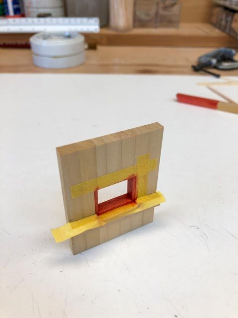
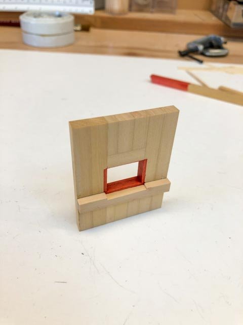
A little bit of creep into the grain, as expected.
Then I planked up the sides and top, using the jig. I have also modeled the wale, in this mock up, because this will be the most complicated paint intersection I have to worry about. The wale is black on the face and tops and bottoms, except at the port cill where it is also painted red on top. I need to study how all of this will work cleanly.
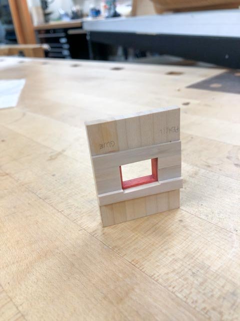
And tomorrow, I will try druxey's method of painting the Floquil Caboose Red on the edges of the planks. We will see....
Mark
-
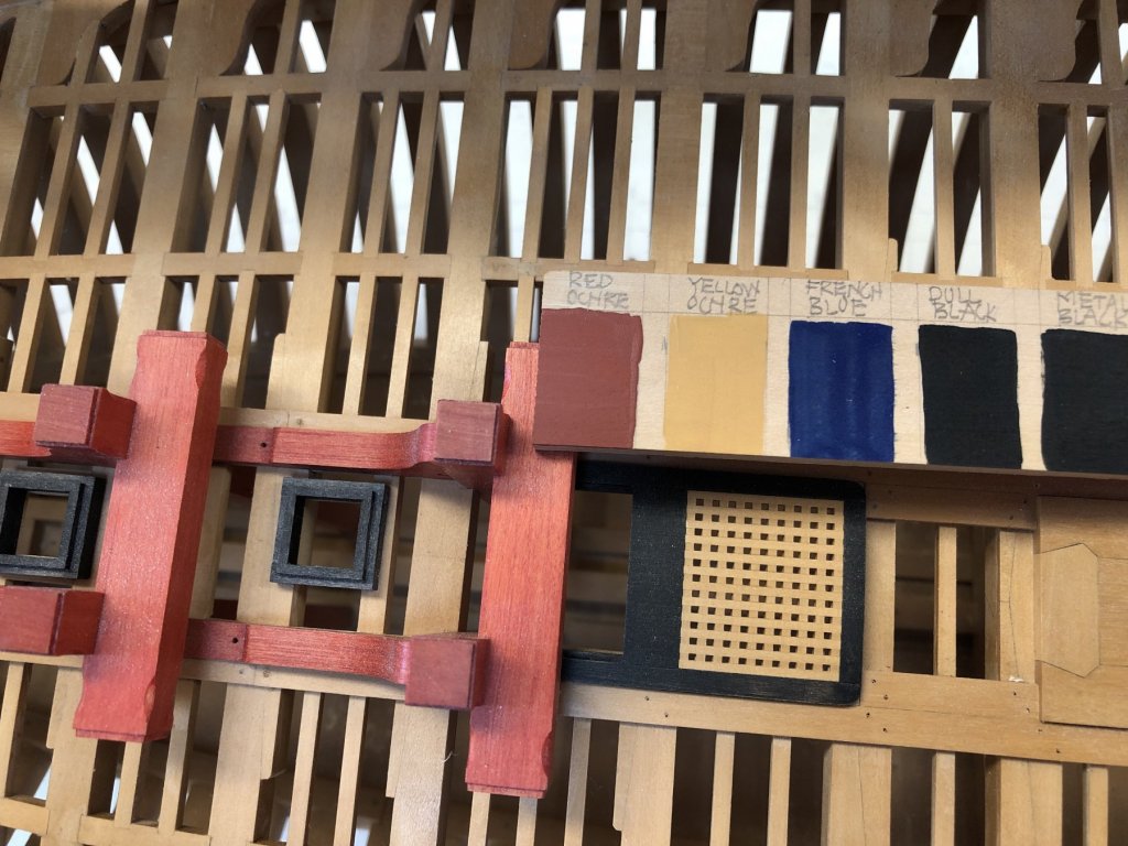
Two steps forward, one back. I was ready to start planking today, then remembered that I need to resolve how to paint the red at the ports.
The Admiralty Paints Red Ochre was way too orange to match the red on the Bellona second model. So am back to the idea that I can continue to stain red parts throughout the ship where I don't have to worry about creep along the grain; and then carefully paint the edge of the planking at the ports with acrylic paint to match the stain.
I discovered that an old jar of Floquil Caboose Red is an almost perfect match to my stain, although obviously it is more opaque than the stain.
But before trying this out on the hull itself, I have made a mock-up of a port, which I will use to test the stain + paint idea and see how it looks and works. I will also explore the idea of painting the edges of the planks just before I glue them in, saving problems with masking this thin edge.
No wonder it takes me so long to move this model along...
Mark
-
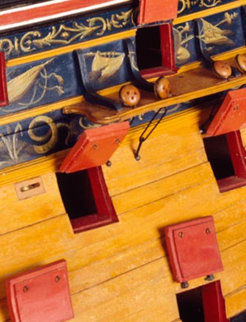
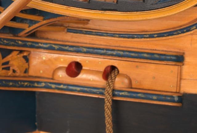
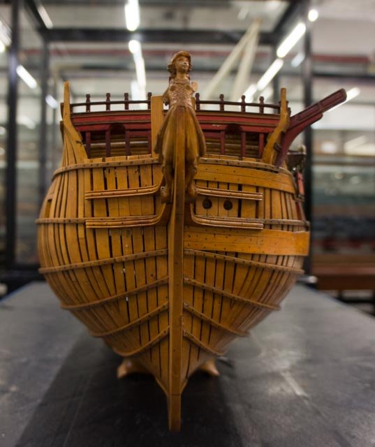
While installing the hawse lining/planking pieces, I had occasion to look at the dimensions of the hawse holes. Both Steel and the Shipbuilder's Repository call for 1'-5" diameter holes, "after the pipes are let out". And they call for hawse lead pipes 1 ½" and 1 ¾" thick respectively. I notice that the hawse holes in both the first and second contemporary models seem a smaller diameter than 1'-5". In the models below, the distance between the cheeks is 2'-3", and you can see in the finished model that the hawse holes are about half the distance, or about 13". And the models don't show the hawse pipes, only a clean hole drilled through the bolster and the lining.
So, could the models be showing the actual diameter of the hole with the pipes installed but not indicated, which would be 1'-1" for Steel (1'-5" minus 3" lead pipe thickness)? Interesting that they don't show the hawse pipe exposed to the outside. Surely the lead would run all the way out over the bolster, if it were there to protect from wear.
Mark
- mcpwilk, druxey, Jorge Diaz O and 7 others
-
10
-
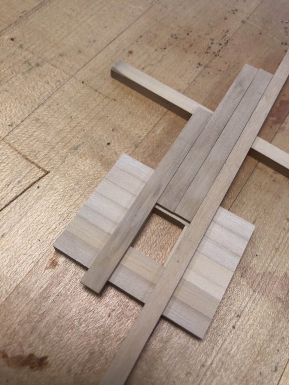
At last, sawdust created again. I decided on a modelmaking cheat at the bows. The actual construction has the black strake and all planking above running all the way into the rabbet at the stem. Later, a thin lining is added over this planking between the upper and lower cheeks, through which the hawse holes are eventually drilled. I decided to combine the planking and the hawse lining piece as one part, the thickness of the planking plus the lining. I would rather fit one piece to the bow, than one and then another on top of it. The black strake and one additional strake will butt into the aft end of this piece, and one will never see if they run under the lining or not.
And instead of messing with the steamer for this short thick part--the two parts combined are as thick as the wales--I sawed these to the curve at the bow. A fun change from steaming. Only a few thin planks plus the thicker channel wales will remain to be bent around the bows.
Mark


HMS Bellona 1760 by SJSoane - Scale 1:64 - English 74-gun - as designed
in - Build logs for subjects built 1751 - 1800
Posted
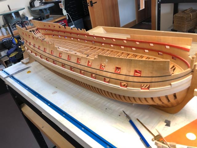
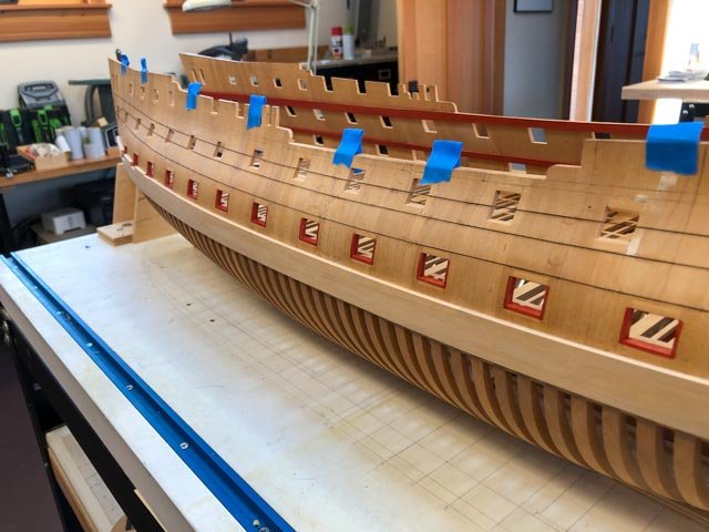
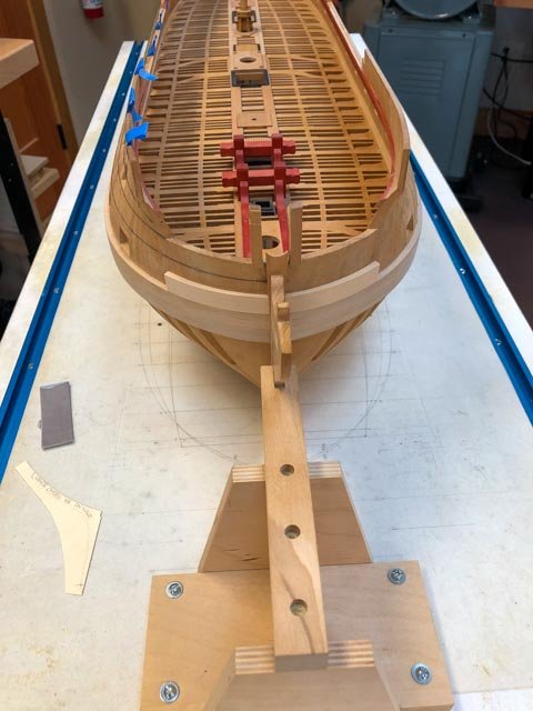
I forgot to attach the photo showing the starboard side black strake complete, except for trimming to the stern. The final piece tucked around nicely.
On to the port side.
Mark