SJSoane
-
Posts
1,655 -
Joined
-
Last visited
Content Type
Profiles
Forums
Gallery
Events
Everything posted by SJSoane
-
 Hi Ed, This is a really dumb question, but I was looking at volume 2 of your book set, and I did not see how you were holding the hull upright on the building table after the rudder was installed. Your distance photos don't show supports at the fore and aft ends, nor supporting chocks underneath. Or did I miss seeing a photo? And since you were regularly turning in upside down, did you have a foolproof way of putting it upright and guaranteeing it was level athwartships, or did you need to re-level every time you flipped it? You continue to be my guide.... Best wishes, Mark
 -
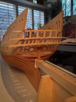
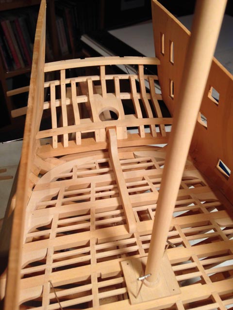
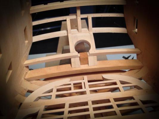
Hi everyone, Big event today. I started on the stern before Christmas, and today I finally glued everything except the upper and lower counter moldings and the two vertical counter timbers above the gun port cills. The moldings need profiles shaped before gluing, and the remaining counter timbers need a little more fitting. It is all looking shipshape! Very, very slow progress on this. Good thing I am not doing this for money.... Best wishes, Mark
-
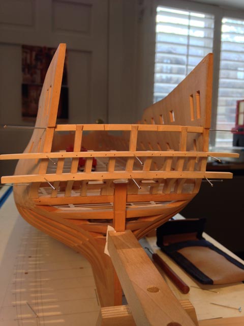
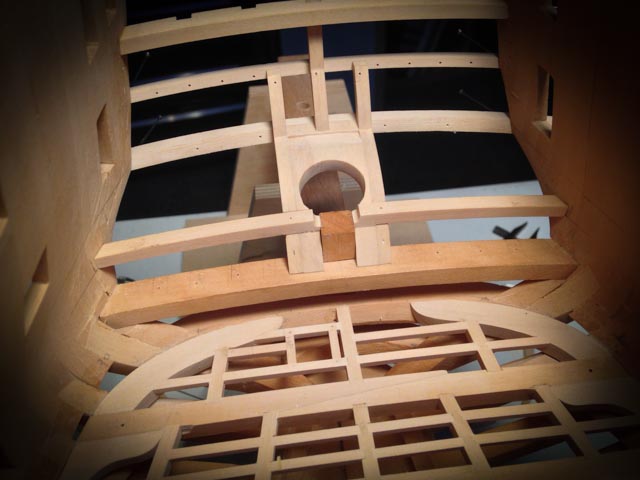
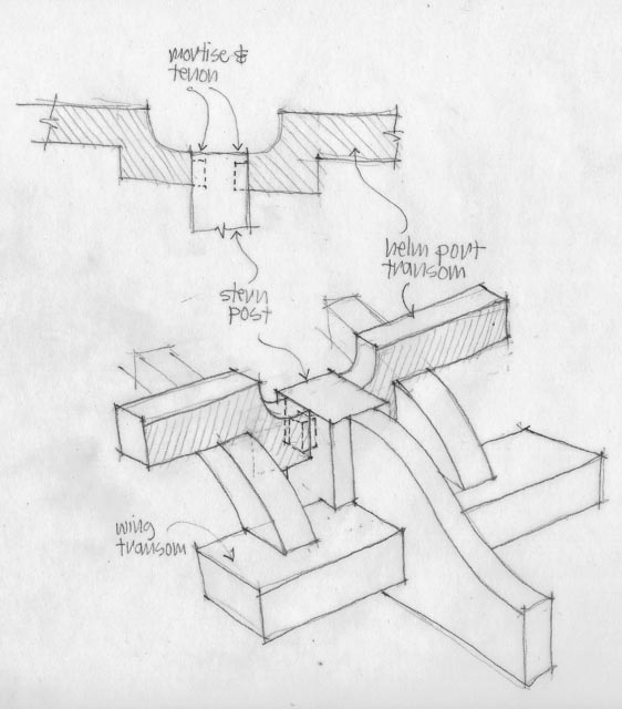
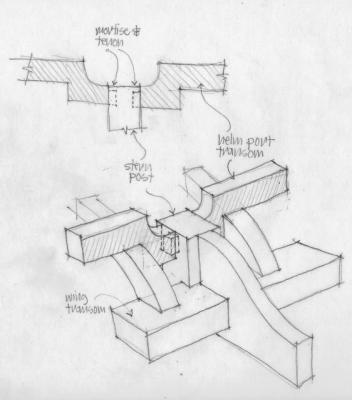
Hi everyone, So I finally figured out--I think--the intersection of the helm port transom and the stern post. After reviewing the photos of the original Bellona model very carefully, the helm port transom clearly intersects the stern post a little aft of center, with a bit of stern post both fore and aft of the helm port transom. So what kind of joint would suit this? I considered a bridle joint intersecting the stern post. But I abandoned this idea, because this would weaken the post at the top by splitting it in two for the helm port transom to pass through. And I began to think that the continuity of the transom all the way across the stern for structural integrity was not necessary anyway. If the transom is split to save the integrity of the post, the two pieces of the transom still bridge on either side between two strong and stable anchoring points, the outer counter timber and the stern post. Furthermore, the upper deck transom (not shown yet in model or drawing) is only a little way above and aft of the helm port transom, and it bridges entirely across the stern giving all the transverse structural integrity needed here. So accepting a split helm port transom, the joint to the stern post is either a dovetail or a mortise and tenon. Maybe I decided on the latter because I did not see how easily I would cut a dovetail in the top or the stern post at this late date. But I prefer to think I decided on the mortise and tenon because it would leave the stern post most structurally integral, and would provide no joint on top of the post for admitting water. This is my story and I am sticking with it.... The drawing shows the intersection without the lower chock for clarity, while the model shows the chocks in place, hiding the lower piece of the helm port transom on either side of the stern post. Best wishes, Mark
-
Thank you, Michael, Sailor, Druxey, Ed and Grant. Each week, I keep thinking I will finally be able to show the stern assembled and glued; but entire days go by with file and fit, file and fit. It really helps keep me going in these more tedious moments with your words of encouragement! I just have to remind myself that a model maker did exactly this same thing 250 years ago, on the original Bellona model. And probably by candlelight as deadlines approached... Best wishes, Mark
-
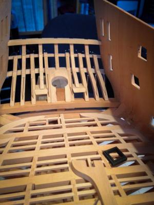
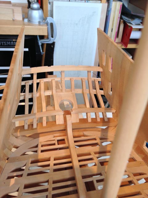
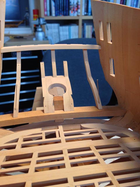
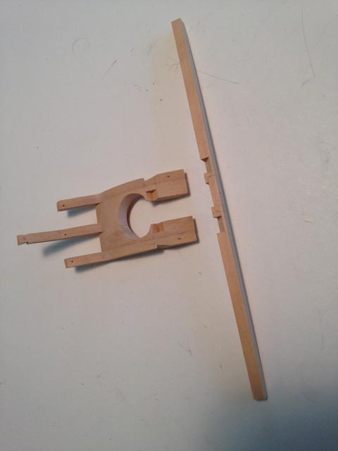
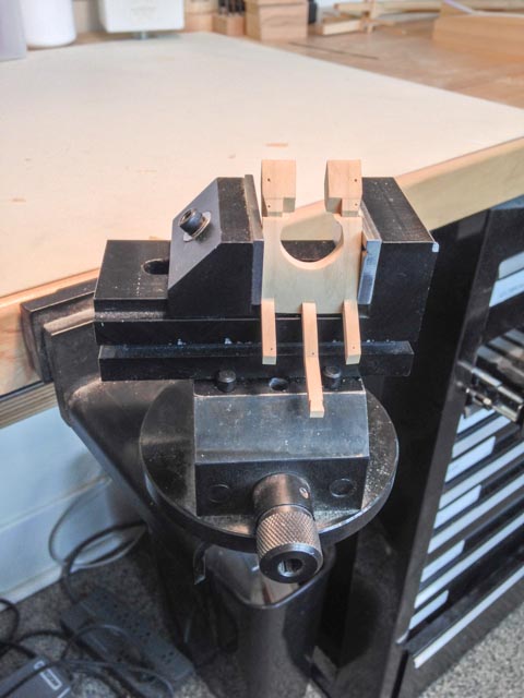
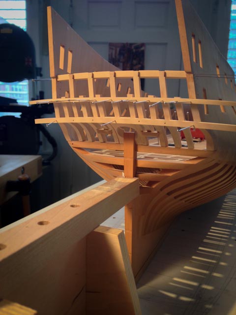
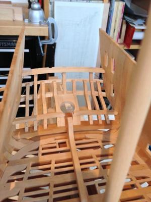
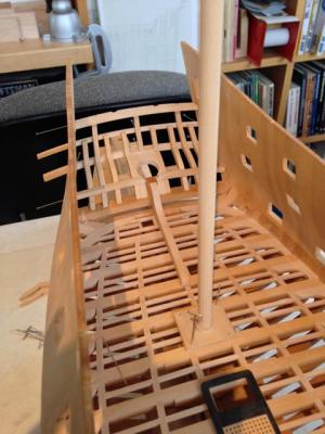
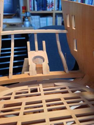
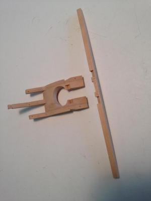
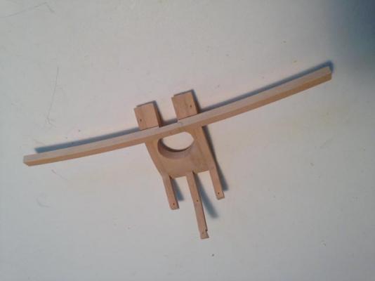
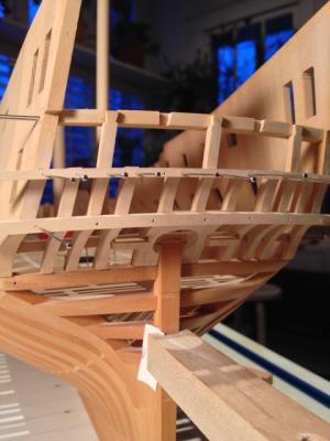
Hi everyone, I continue to work on the stern, which proves to be the most complex thing I have ever built. Each piece interacts with several others, like a basket-weave. Nothing can be finally fixed, until others are fixed, which in turn depend on the first piece, etc. I discovered that even pinning things together doesn't entirely work, because the pieces move enough that fine fitting of another part is always off a bit. So I decided to firm up the middle, with the rudder port chocks glued to the two adjacent vertical timbers, holding the center timber. With this as a foundation, the other parts can be fitted to something solid. That center piece was a bit tricky to shape, and I am showing a Sherline vise held by my bench vise, which allowed it to be held without breaking the open end. I am also showing the helm port transom on the fore side of the timbers. Eventually, it will be cut in the middle, to come down to the top of the stern post. But I decided to keep it whole while fitting everything, to keep everything in alignment. I keep thinking I am only a short time away from gluing it all up, but each little fitting of parts takes forever. Maybe next week.... Best wishes, Mark


-
Nice, Remco! I am glad the jig idea worked for you. I would be lost without it. I am sure we will both be happy when we construct and install the window frames, knowing everything is already accurately spaced and hopefully symmetrical. Did you cut that very clean rabbet in the fore edge of the transom with a hand chisel? Best wishes, Mark
-
Michael, it is time to consider running a workshop on metal work. You are the master! Mark
-
Thanks, Ed, that is a very thoughtful answer to the question of how the clippers could be pared down to minimal structure necessary. It is always a design aspiration, to get the most done with the least material.... Mark
- 3,618 replies
-
- 1
-

-
- young america
- clipper
- (and 1 more)
-
Hi Ed, Very interesting, to see the inboard works of the clipper compared to your Naiad. So there are no riding timbers or other transverse structural members in the lower hull? Or is that still to come? Mark
-
Gaetan, Those head rails are visual poetry. Those shipwrights were geniuses of function and art. Mark
-
ROYAL CAROLINE 1749 by Doris - 1:40 - CARD
SJSoane replied to DORIS's topic in - Build logs for subjects built 1501 - 1750
Doris, It is so rare to see so many crew on these models. It really brings the ship to life, and gives it a great scale. A masterpiece. Mark- 883 replies
-
- 1
-
-
- royal caroline
- ship of the line
- (and 1 more)
-
I would add to the previous comments that a book on this topic by you would be a best seller! Mark
- 3,618 replies
-
- 4
-
-
- young america
- clipper
- (and 1 more)
-
Hi Michael, I am not getting much time away from work to check on the website lately, but I did stop in to see your progress. Looking great! Mark
-
micro table saw stop
SJSoane replied to michael mott's topic in Modeling tools and Workshop Equipment
I would add that cutting the thin piece on the fence side means that you cannot easily use a push stick. I use one that hooks over the fence, and has some sandpaper on the bottom surface to grip the stock. It keeps the stock flat on the table, and tight against the fence. this helps avoid any vibration in the cut. But this needs enough stock between the blade and the fence to give clearance for the push stick. Much easier and safer to cut the thin piece off the blade side, and then index the fence over with the stop for the next cut. Mark -
Michael, I keep forgetting that you are actually going to sail this. A whole new set of complexities! Mark
-
ROYAL CAROLINE 1749 by Doris - 1:40 - CARD
SJSoane replied to DORIS's topic in - Build logs for subjects built 1501 - 1750
Doris, Every crew member added makes it even better! Mark- 883 replies
-
- 1
-
-
- royal caroline
- ship of the line
- (and 1 more)
-
Thanks, Mark, don't you sometimes feel you are channeling model builders from the 18th century, when you make exactly the same piece you know they made 2 ½ centuries ago? Thank you Doris, coming from you who is one of the very best builders on this site, this is a very high compliment!
-
Michael, Just scale up those metal fitting to full size, and you could open a boat chandler shop. Can you do a line in flotation devices? ;-) Forging--beyond my comprehension how you do it, and do it so well. Mark
-
Thanks, Michael. I don't know how I would have pulled this off without a jig. Each piece depends upon several other pieces to locate it, so everything is floating around without something to anchor it at least temporarily. And now the most important part--equal spacing of the window frames--is guaranteed by the original spacing in the jig. I can only imagine how the original shipwrights located these two story tall counter timbers. There must have been lot of shoring and propping... Mark
-
Beautiful, Alex, exceptional craftsmanship. Mark
-
Hi Michael, Your metal parts are so well done they look full scale; until I see your hand in the photo. Exceptionally well done! Mark
-
Very nice, Alexandru!
-
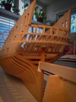
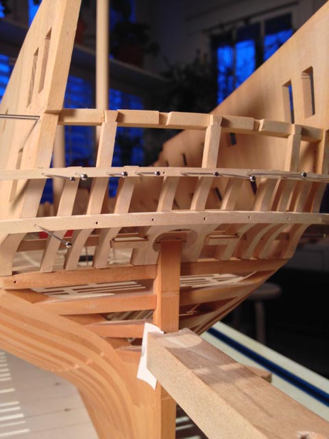
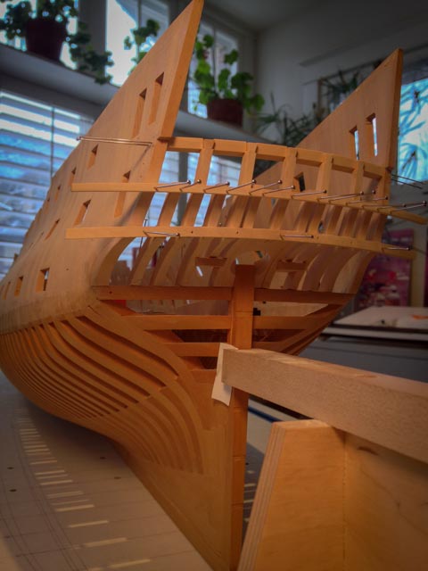
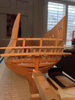
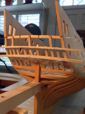
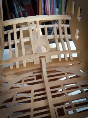
Hi everyone, After many months, I was finally able to remove the jig today, and see the stern in all its glory. I still have to trim the short pieces in the window sill area, and fair inside and out before finally gluing up and starting the transoms inboard. But it is definitely looking more like a real stern. The whole thing is shockingly fragile. No wonder a broadside into the stern would just about finish the day.... Best wishes, Mark