HOLIDAY DONATION DRIVE - SUPPORT MSW - DO YOUR PART TO KEEP THIS GREAT FORUM GOING! (Only 13 donations so far - C'mon guys!)
×


keelhauled
-
Posts
788 -
Joined
-
Last visited
Content Type
Profiles
Forums
Gallery
Events
Everything posted by keelhauled
-
 Thanks Popeye! Unfortantely, I had to undergo an emergency surgery last week, so it might be a few weeks before I get back to modeling. I appreciate the encouragement it really means a great deal to me! take care, Marc
 -
Thanks, As long as someone is enjoying looking at the build I'll continue to post. I really enjoy reading everyones' builds.
-
I hope that i haven't offended anyone by my comments about the kit. I think that the kit is well done and a model built directly from the kit and plans will be a very fine model. I just wanted to make some stuff from scratch and improve (at least in my mind) some aspects of the kit. I'm sorry if in doing so, I've upset you in anyway. Marc
- 525 replies
-
- 2
-

-
- cutty sark
- mantua
- (and 2 more)
-
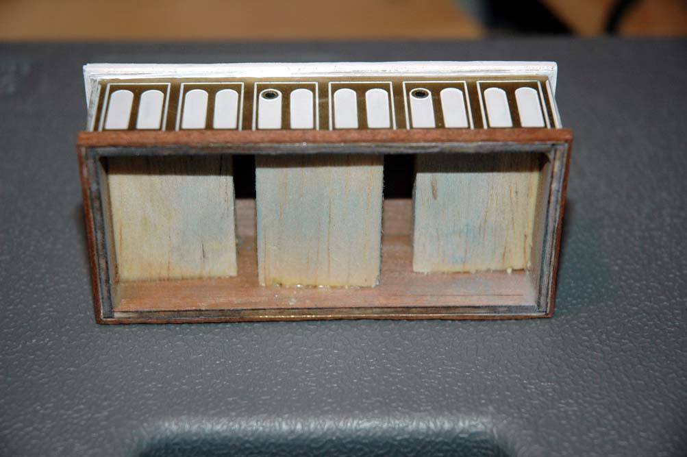
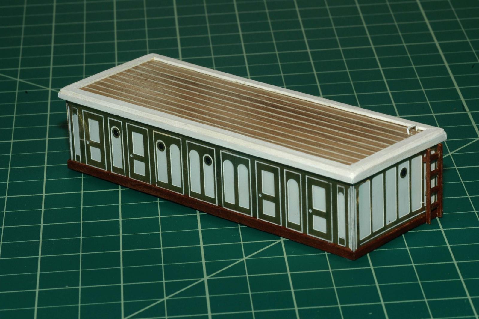
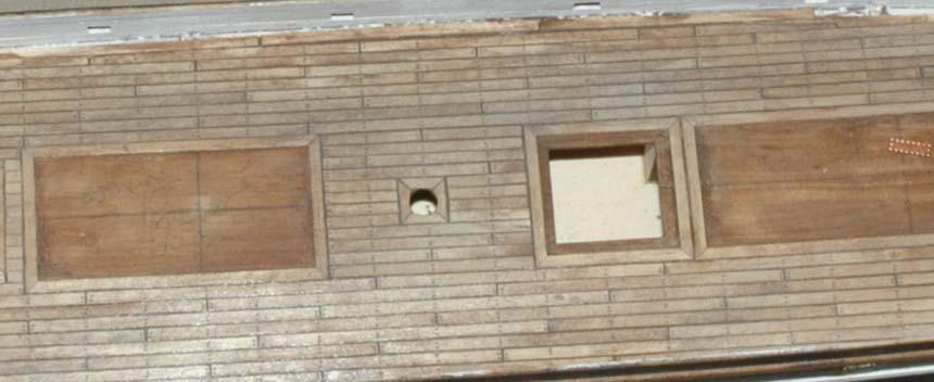
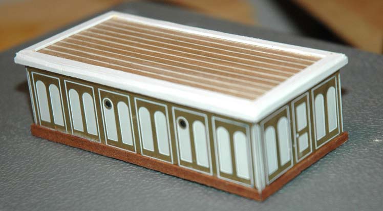
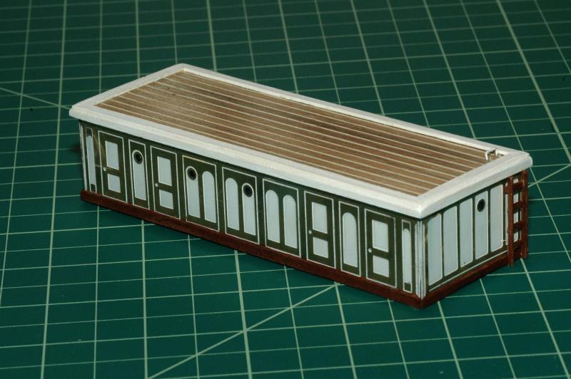
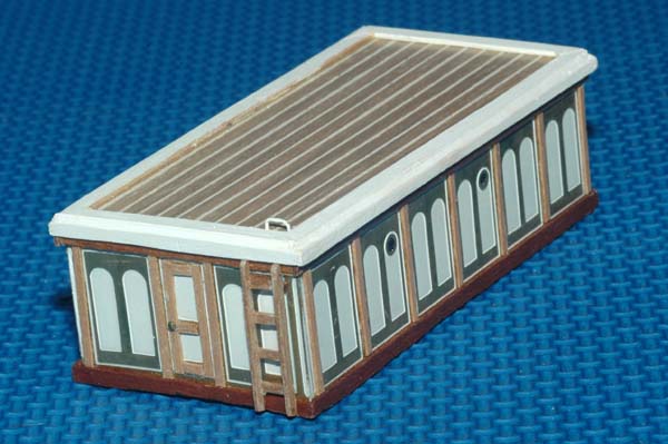
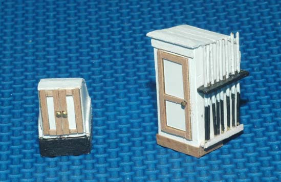
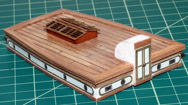
Here are some of the work that i've done on the deck houses. The foward hatch on the model was only a wooden hatch cover. Campbell had it as having doors and removable wood hatches/boards. I built the deckhouses per the kit instructions and then reenforced with wood blocks. I also made white caulking for the roofs using lil pins as spacers between the planks and then filled with white wood putty, then sanded. The kit has the bright teak as brass. I think this looks fine. I wanted to see if it looked any better with walnut. After the results, I'm not sure it is an improvement. reinforecement bocks inside the deckhouses I soldered the beams and bars in brass for the saloon skylight. I also made a smoke stack using brass tubing (it's not shown in this picture). Also to make the entrance back to its 1890s version, I made the new one from scratch and split one of the kit side doors to make the front door. foward hatch and WC. I added the walnut bright work and the captan bar holder


- 525 replies
-
- 2
-
-
- cutty sark
- mantua
- (and 2 more)
-
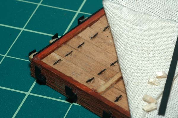
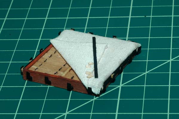
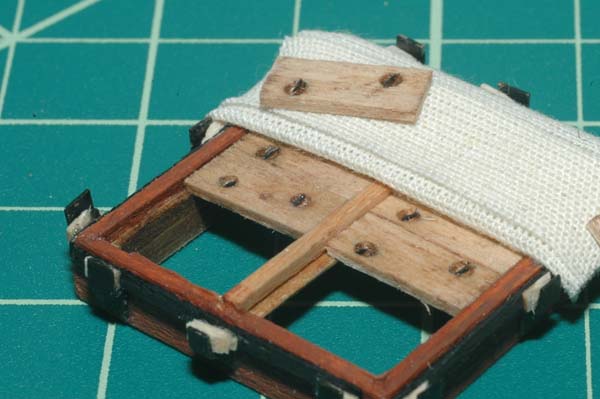
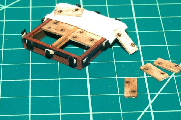
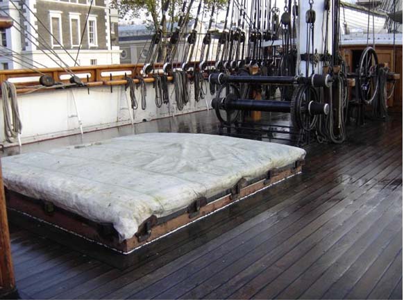
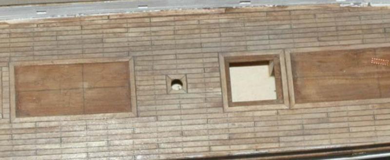
I scratch built the hatches, combings, wedges and brackets. The kit had oversized grating covers. I made the frame for the hatches complete with a removable beam (strongback) and hatch coaming. A photo I took inside the Cutty years ago clearly showed the these details as well as the wooden hatches. Likewise I had an old photo showing the wooden hatches with handholds. I created the hatch cleats and flat bars with brass. I made the handholds in the hatches by using a large drill to make the recessed part of the hold and then used a strand of speaker wire painted black as the bar. I placed the tarp in place, put the bar along the cleats and secured the wedges. I used adhesive used for locking knots in pearl necklaces to glue the tarp in place. The adhesive doesn't discolor the fabric. I think the results look good. My attempt at the forward hatch the actual Ship's aft hatch My attempt at the aft hatch
- 525 replies
-
- 2
-
-
- cutty sark
- mantua
- (and 2 more)
-
Great work! She's beautiful! Nice job on the rigging. Marc
-
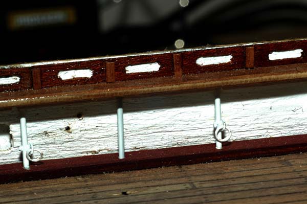
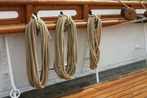
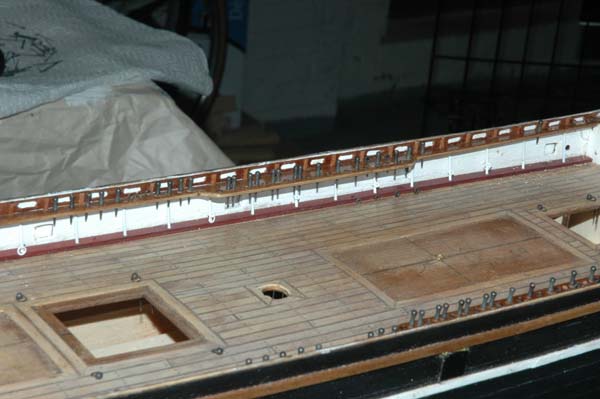
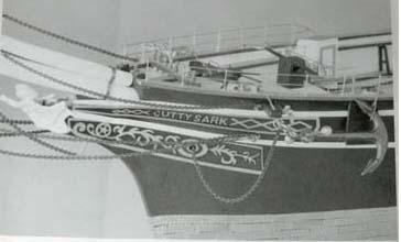
HI! I started work on the bulwarks. The kit has very large wooden stanchions, which I didn't think reflected very accurately what was present on the actual ship. I had been following another modeler's build and he had replaced the kit stanchions with scratch made versions which I think looked much better. I asked him how he did it and he was kind enough not only to explain, but send a couple of extras for me to replicate. There are essentially three different types of stanchions with two main groups: those with rings and those without. I followed Longridge's book to the types and placement. So the stanchions are mad with brass rods. Pintels are bent and soldered to the rods to make the brackets to hold the rings. To secure the rods into place, I drilled holes into the water ways and made a very small rail which fit under the main rail and had cutouts for the tops of the stanchions. The other change I made from the kit was to include the panels between the main rail and the topgallent rail. I made the oval cutouts by making a jig to cut two holes for the ends of the cutouts and then cutting between the holes with an xacto knife. I thought that the effect looks pretty good. especially when viewed at a normal distance from the model. You can find a jpeg with the graphical explanation at http://modelshipworld.com/index.php?/topic/1000-cutty-sark-by-keelhauled-mantua-kit-bashed-first-wooden-ship-build/page-4#entry122099 The actual ship bulwarks and stanchions The Kit Stanchions The model with scratch built stanchions and panels another view. I think that the kit size of the belaying pins is too big. I'll try another size.

- 525 replies
-
- 5
-
-
- cutty sark
- mantua
- (and 2 more)
-
Thanks Gary!
-
Thanks Hamilton! I thought that they looked better than the etched brass that came with the kit. I still need to do the name boards. Not quite sure how to go about it. Any suggestions would be helpful!
-
Wow. Awesome work! looks like you are building most things from scratch. really nice! Just a note, the spreaders on the trees are supposed to move the stays out and it does angle them. Just like you have it and it's the same on the real ship. modern small sail boats use the same principle.
- 237 replies
-
- 2
-
-
- cutty sark
- revell
- (and 2 more)
-
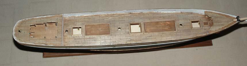
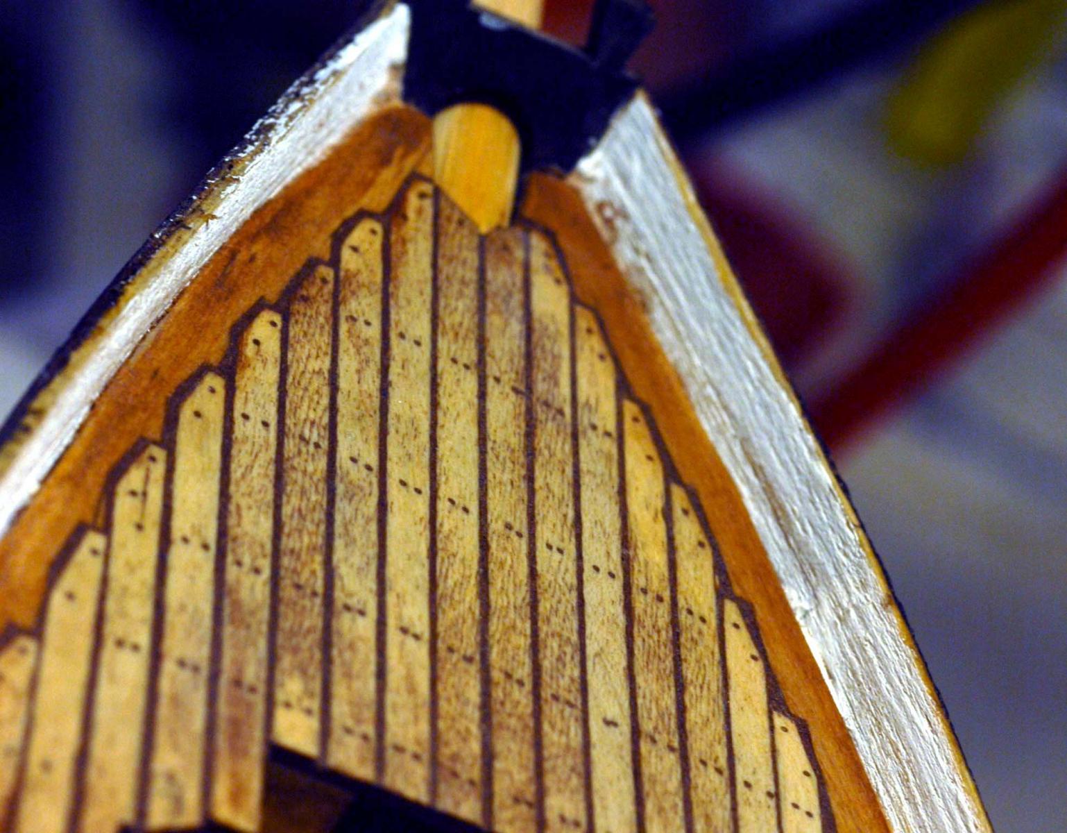
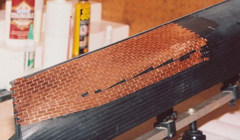
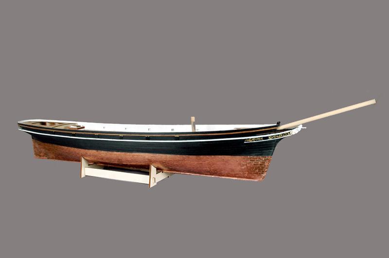
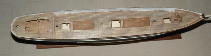
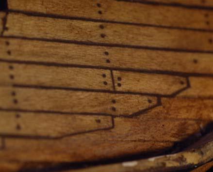
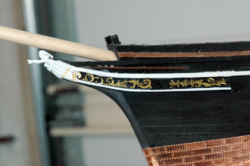
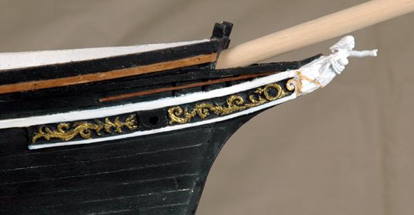
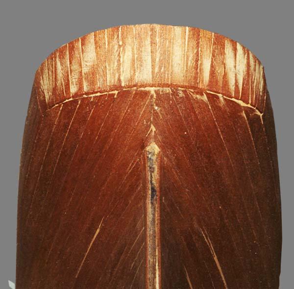
My Coppering Nightmare! After planking, I lightly sanded and painted the hull. Big mistake number 2 - don't paint and sand where you are going to copper I did and had to go back and rough it back up. I then coppered the bottom with the supplied plates. So I looked at books and articles as well as asked another forum for input as to what glue I should use. Several sources recommended rubber contact cement. So I coppered thehull. It looked beautiful. I walked into the shop one hot Florida day and the plates were on the bench and floor instead of the ship . They just flowed down the sides like lava . I asked another forum (drydockyard) and the consensus was to use superglue/cyanoacrylate - the gap filler version. So after days of cleaning the two thousand plates, I sorted them into containers according to shape and then spent twice the original time to re-copper the hull. Everything once again seemed secure. Then slowly the plates started popping off the hull during the winter months in my Virginia home . I once again asked for help. They consensus was to roughen up both theback of the copper plates and hull on the plates that came off. Plates continued to pop off even those roughed up. I also tried 3 different brands without any difference. I landed a job where one of my co-workers was a fabrication engineer. I told him my problem. He told me to scrape the plates and hull and then clean with acetone to remove all cyanoacrylate. Then dig a criss-cross pattern on both the hull and the plates and then use two part epoxy. I tried it and I have never had one of these plates come off (it's now been about 8 years) . Slowly over two years while working on the ship I would tap all of the plates knocking the cyano plates off and reattaching with the epoxy. After coppering (the initial coppering) I then painted the bulwarks and planked the deck. I used the same planking scheme as the ship according to Longridge. I found a reference for using dark wood putty for caulking, so I used the tips of little pins and spaced the planks. I tried my hand at jogging. It turned out ok I thought. I sanded the decks and then stained them using layers of minwax stain diluted and different colors including teak and a weathered grey. I thought that the variation resembled the variation in color that you see in the teak when some of it is wet and some dry. I was walking on the deck of a ship after the rain and the teak was drying. I thought that the result here looked similar. I then sealed the deck with two coats of clear accrylic. I also put two coats on the hull and bulwarks. I rubbed it all down very lightly with very fine steel wool to reduce the sheen a little. I build the knees and rail on the bow. This detail isn't in the model plans. I also mounted the figurehead and carved the scrollwork using sharpened jeweler's screwdrivers. This is the first time I've ever tried to carve. I think that it turned out well. the Kit bow for reference


- 525 replies
-
- 5
-
-
- cutty sark
- mantua
- (and 2 more)
-
Hi Bob, Thanks for the support. I was working on the next post when your replied and didn't catch it unitl now. Cheers, Marc
-
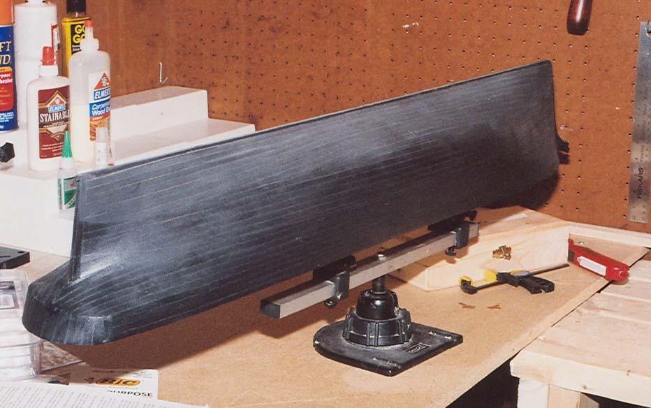
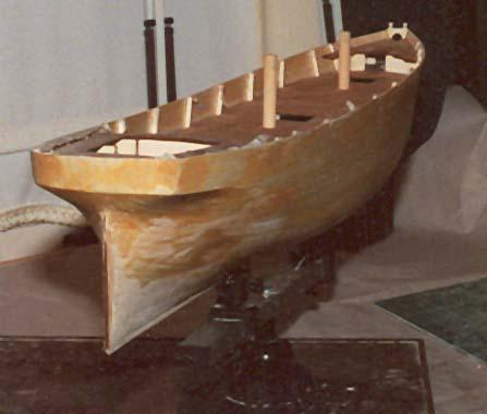
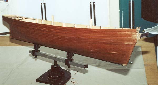
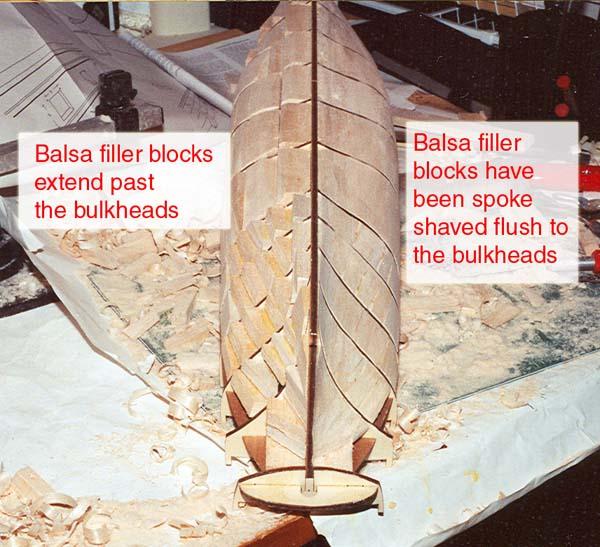
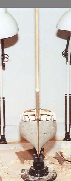
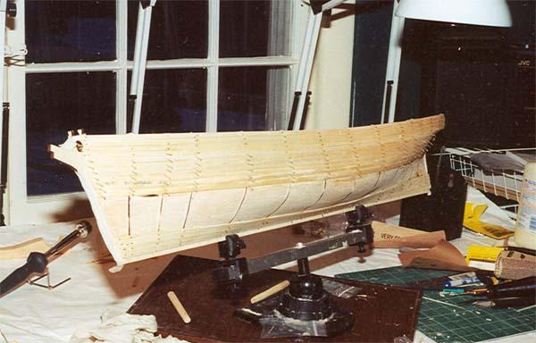
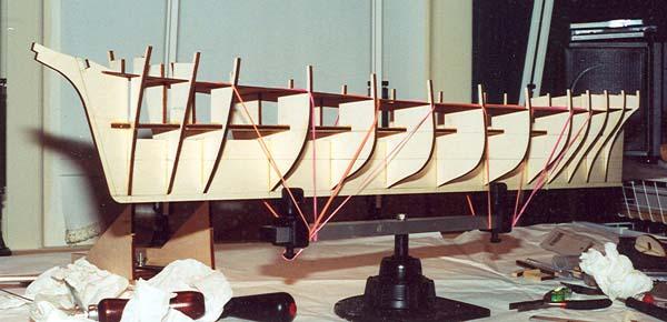
PLANKING THE FRAME The model kit has attaching the sub decking into place as the next step. So with the frames having been securely glued into place I tried placing the sub decking into place. I found that the decking would form to the contour of the bulkheads without requiring any soaking in water. I dry fitted everything and then glued the joints. To secure the deck to the bulkheads I used an amazing clamp – the rubber band! I love these as a clamping device and use them when I can. I followed the next step in the instructions which was to plank the frame. I’ve since learned that life would have been much easier if I had planked the deck! In fact, many professional modelers suggest planking the deck before the hull. I wished that I had. Such is learning. The Amati ship vise is holding the ship in the following pictures. It is by far one of the best investments that I’ve made. I highly recommend it. It clamps to the keel. If you place dowls into the mast steps, you can clamp the hull upside down. The clamp swivels and tilts. It’s awesome. Before planking the ship I follow a recommendation found in several articles that were written by Robert L. Evans for Ships in Scale (Upgrading the Kit Part 1, May/June 1994). One suggestion was to use balsa wood as a filler to make up for the lack of an adequate number of bulkheads supplied with kits. I found in other articles that the lack of an adequate number of frames or bulkheads in the models often results in concave dips in the hull, especially with ships that have flat runs such as clippers! So two solutions were put forth create additional bulkheads or use balsa as a filler. I chose to use balsa filler blocks per Evans example. This model is double planked. The nice part about double planking is that you can practice on the first planking. Since there are numerous sources for planking, I won’t go into any detail. I used a palm nailer and lil-pins to do the first planking. The second planking went very fast. I used contact cememt to secure the second planking instead of pins/nails. The model kit used vertical boards to create the curve of the counter as opposed to creating the curve with bending planks around the curve. Since I was going to paint the ship and the fact that the counter was iron, I wasn’t concerned with how the curve was made, just that the it was made accurately.
- 525 replies
-
- 4
-
-
- cutty sark
- mantua
- (and 2 more)
-
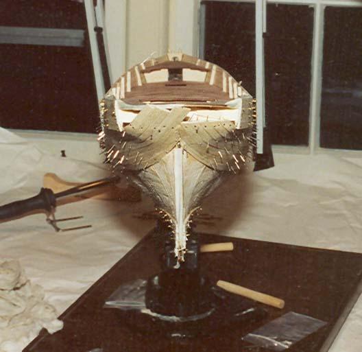
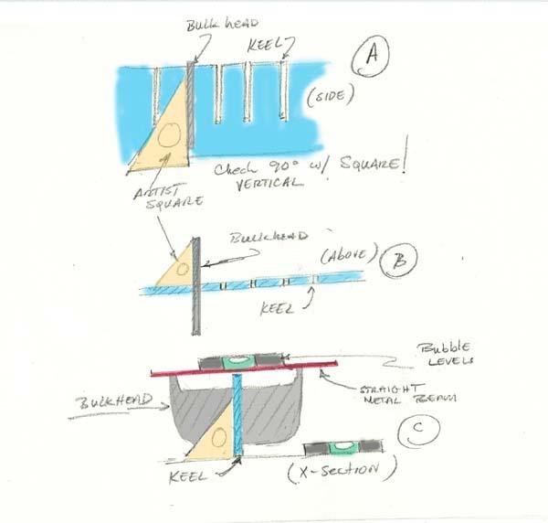
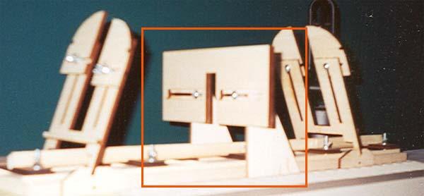
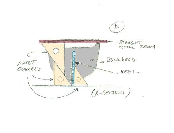
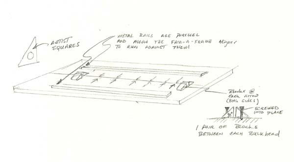
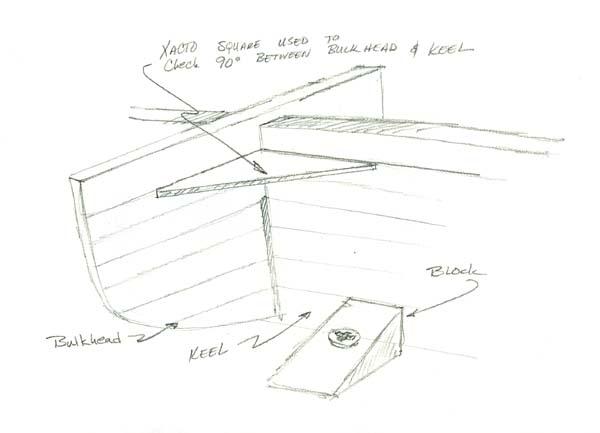
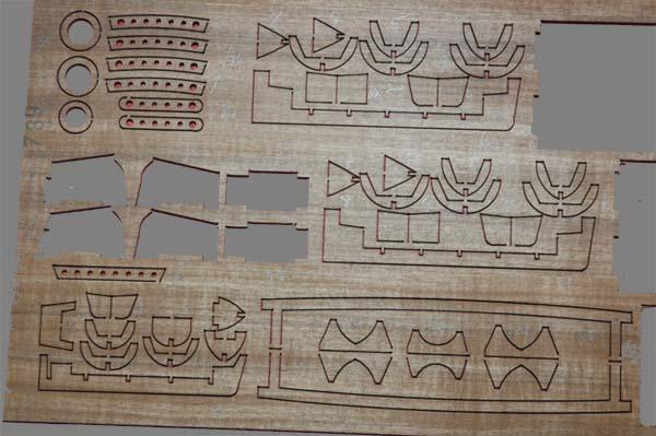
BUILDING THE KEEL AND BULKEADS The keel and bulkheads are hardwood plywood and are laser cut. I checked their mirror image and against the plans. They needed very little adjustment. The keel is provided in a single sheet, so you don't have to gule separate sections together - which is nice. The sheet that the keel was on was straight and required no straightening. As I was buying my models I came across a contraption called Fair-A-Frame, which claimed to make aligning the keel and bulkheads a simple and fool-proof procedure. This was my first build - so I bought it. - I'd give it mixed reviews. There wasn't enough clearance between the keel clamps and the bulkheads to use it for the Cutty. For the Cutty I had to build a jig using wood blocks and metal beams. I did end up using part of the Fair-A-Frame which rides perpendicular along two strips of wood which are parallel to the keel and thus when it pushes up against the bulkhead it forces the bulkhead to be 90 degrees to the keel. – It works but I don’t trust it. I think it would probably be fine for smaller models. To build the jig I used a flat board as the base and square sides. I used an artist T-square and marked the center. With the square in place and clamped to the board, I placed wooden triangle blocks with a 90 degree angle, up against the T-Square and srewed them in place. This way I knew that they were all parallel with each other and in a straight line. They were positioned so that they would be between the bulkheads. With the one side of blocks in place, I put the keel up against them and placed the other set of blocks tightly against the keel, clamping the keel between the blocks. I checked the alignment with an artist square “athwart ship” and with the T-Square on the backs of the blocks this time to check the fore to aft straightness. I then placed the Fair-A-Frame part which rides parallel to the keel on the keel and centered it. I then marked of the ends and used the T-square to align two metal beams for the part to ride on. I’ll diagram it, if anyone cares. I ended up checking everything with squares anyway, so I’m not sure how much I really used it. I was VERY concerned with making sure that the keel and bulkheads were aligned correctly. I found several articles that were written by Robert L. Evans for Ships in Scale (Upgrading the Kit Part 1, May/June 1994). Based on his suggestion, I marked parallel lines every 2mm on both the bulkheads (both sides – fore and aft) and the keel that paralleled the waterlines. This way if the lines on thebulkheads matched the keel I knew that everything was pretty close to being true. I checked the alignment by placing a square on the edges of the line markings The bulkhead and keel alignment were checked in all dimensions using artist squares (triangles). I checked to make sure that each bulkhead was aligned vertically (A), athwart ship ( and cross sectional (C and D) In C, I placed a straight metal beam across the top rails on the bulkhead and placed bubble levels on the base and the metal beam. I made sure that the base was level and then checked to make sure that the bulkheads were level. In D I also used two artist squares to make sure that the metal beam was parallel with the base as a double check. After I drove myself crazy making sure the bulkhead was aligned correctly with the dry fit I removed the bulkhead applied Elmer’s wood glue to the slots on the bulkhead and keel and replaced it. I glued the seam on each side then checked the alignment all over again. I only glued one to two bulkheads a day to make sure that everything was lined up. I worked from the stern to the bow. Rubber band clamps - awesome! So here was my first mistake. Per the instructions, I glued the deck. I should have planked it first or at least planked it before planking the bulwarks. It would have made life much easier!
- 525 replies
-
- 1
-
-
- cutty sark
- mantua
- (and 2 more)
-
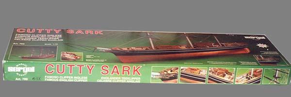
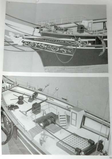
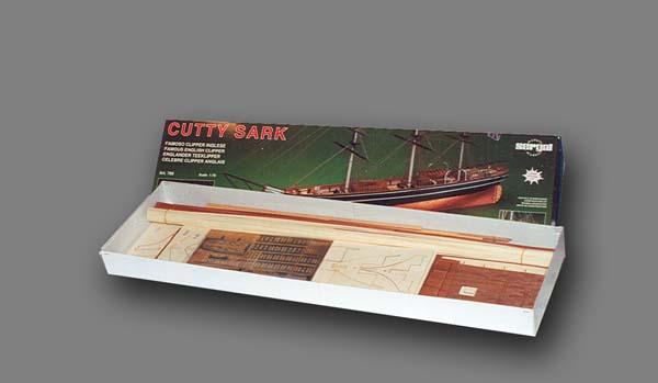
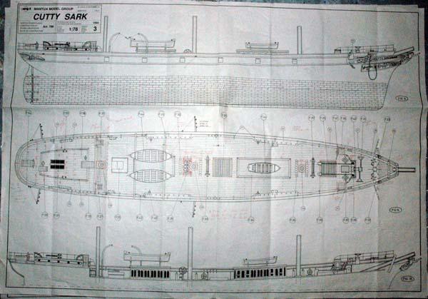
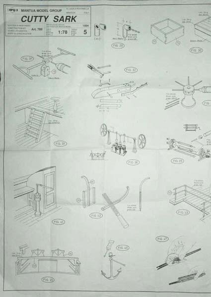
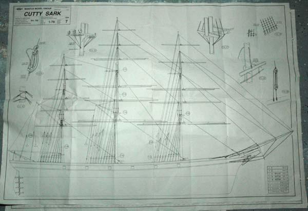
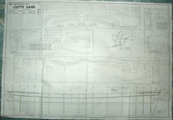
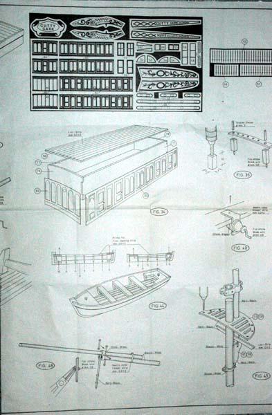
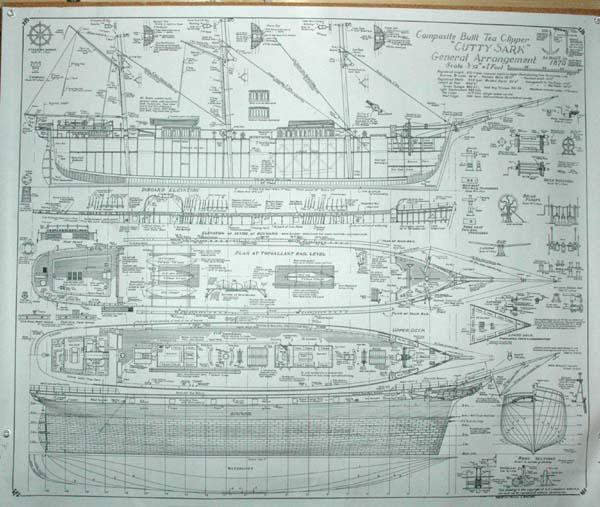
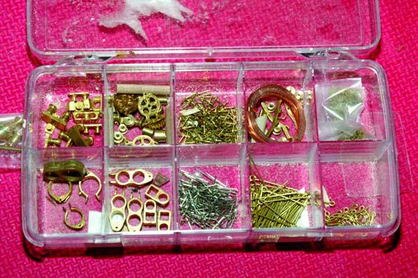
So I started building the kit per Mantua's plans. I then quickly moved over to Campbell's plans. I used Longridge as a guide, but primarily Campbell as the primary source when the two were in conflict. I ended up making much of the fittings from scratch (I'll try to include the model version along side for comparision). I also found that many fittings were not included as part of the kit, so I had to make them. Since this is my first wooden ship model, I had to learn how to make the fittings from brass and wood. Without previous experience I did the best I could. I also included details such as the interior varnished pannels on the inside of the bulwarks. The kit makes a nice model, but I wanted more accuracy and detail. We'll start with an overview of the Kit: THE KIT OVERVIEW Manufacturer: Mantua (Sergal), Italy Model: MA 789 (Art 789) Dimensions: Length 45” (1150mm) Height 26” Scale: 1:78 Purchased: 2001 Price $499-$699 USD (2008) Construction: Double Plank on Bulkhead Planking: Limewood inner, Walnut outer, Maple decking Fittings: brass, copper, bronze, copper plates, walnut dead eyes and blocks, copper sheet with ornamentation and deck siding, bronze figurehead, black and tan cotton rigging line, silk flag. Instructions: Booklet in English, Italian, French, and German (I think – if I’m wrong let me know). Four pages in each language four pages of photos with two black and white photos on each page The instructions are typical from what I've been told. Only very general instructions and not very useful. Plans: Four very large two sided sheets – Eight plans total in four languages. 1:1 sheets for the deck, side, standing, and running rigging. Other sheets detail building steps. Comments: I think that overall the kit is very nice. Mine appears to be the newer version. The fittings, especially the pumps, windlass, capstan, and figure head are very nice. The wood was in good shape. So far there seems to be enough. The kit is supplied with copper plates for the hull. I ran out. I don’t know if they didn’t supply the amount they were supposed to or if 2700 just won’t do the job. I didn’t count the plates – so I’m not sure. Either way I needed an additional 150 plates. If you need extra plates you can purchase them at Model Expo (sometimes they carry them, sometimes they don't). The 1:1 plans were surprisingly 1:1 within a tenth of a millimeter. I checked the plans with a set of calipers against the cast and etched parts. I read several complaints from modelers who had plans that were way off in dimension. These were posts from folks with the older design kits. I don’t know if I got lucky or if their printer is doing a more careful job. Either way always check your plans with a set of calipers. The newer kit has some changes from the two older versions, such as the dimensions of the booby hatch have been corrected. The hatches of the poop deck have been altered to the way the ship has been since the 1890’s. The scale of the inner bulwark stanchions have been corrected – although there are too few and they are still wood instead of metal. More Steps have been added to the ladders. One change that I don’t like is the elimination of the copper bulwarks for the exterior. An etched copper sheet is supplied with the kit that has the side detailing for the deck houses and the scroll ornamentation. The scroll ornamentation is an over scale approximation. If you want to model the ship with the teak finish on the deck houses you can purchase a wood version of the sheet at http://www.laserservices.net/wood.html. I’m modeling the ship as she was around 1872 and from what I can find she had white panels at the time so I’m using the supplied sheet. For the scroll work, I sculpted it on my own (I only did the bow, wished that I had done the stern as well). As I said overall I’ve been very happy with the kit. Recommended References: Cutty Sark Lubbock, Basil: The log of the Cutty Sark, Brown, Son, and Ferguson, Ltd, Glasglow, 1924,1974. Hume ,Cyril and Malcom C. Armstrong: The Cutty Sark and Thermopylae Era of Sail, Brown, Son, and Ferguson, Ltd, Glasglow, 1987. Longridge, C. Nepean: The Cutty Sark, The ship and Model, Argus Books, Watford, Herts, England, 1933,1975. (Comes in one or two volumes (hull and rigging), It has full plans by HaroldA. Underhill. It is a must have!!!!) Campbell, G.F. Three Sheets of Plans for the Cutty in 3/32 scale. One sheet for the hull and decking details, one sheet for standing rigging, and one for the running rigging and sail plan. All fitting detailed out. Very detailed plans. It is another must have. These are available at the cuttysark’s website for about 8 pounds. http://www.cuttysark.org.uk/index.cfm?fa=contentShop.productList&directoryId=6 Modeling (To be continued)
-
Hi, This is my first wooden ship build. I started quite a few years ago, but I'll start the log from the beginning. I'm learning as I go, so I'll let you know my mistakes as well as problems with the kit. Thanks Marc
- 525 replies
-
- 1
-
-
- cutty sark
- mantua
- (and 2 more)
-
Looks great! How did you do the copper? is it tape or separate plates. It looks really good.
-
Looks great!!
-
Looking great! By the way, your windows in the galleries look awesome.
-
Hi Patrick, I'd have four times the finsihed models that I have, if I didn't have to go back and take apart what I've already built due to some issue later on. Post the photos anyway, we can all learn from your missteps. And if you are like me, I won't learn anyway and I'll have your photos to look at and know that I'm not alone!
-
What paints and brushes are you using? The results look great. I know that the majority of the result is the painter, but I just wondering. Great job!
-
Hang in there with the move. I moved Virginia to Florida and back over two years. It was fun moving the models, especially those in progress. Working on the smaller pieces is a great way to stay active! Good luck! Also, very high tech with the candles. I can't wait to see how it looks!
-
Can't wait to see the book! It sounds like they could get quite a few pre-orders on the book. I know I'd be one.
-
Your doing a great job. The pen did a nice job on the seams.