Some Idea
-
Posts
1,159 -
Joined
-
Last visited
Content Type
Profiles
Forums
Gallery
Events
Everything posted by Some Idea
-
 Ha ha thats a far better description of it than a stove - yep its a barbie alright 🤣
 -
Thanks Dave - If you do use square brass tube in the future you can actually sharpen it to help you cut the hole too. Laziness (thats me) is the mother of all invention
-
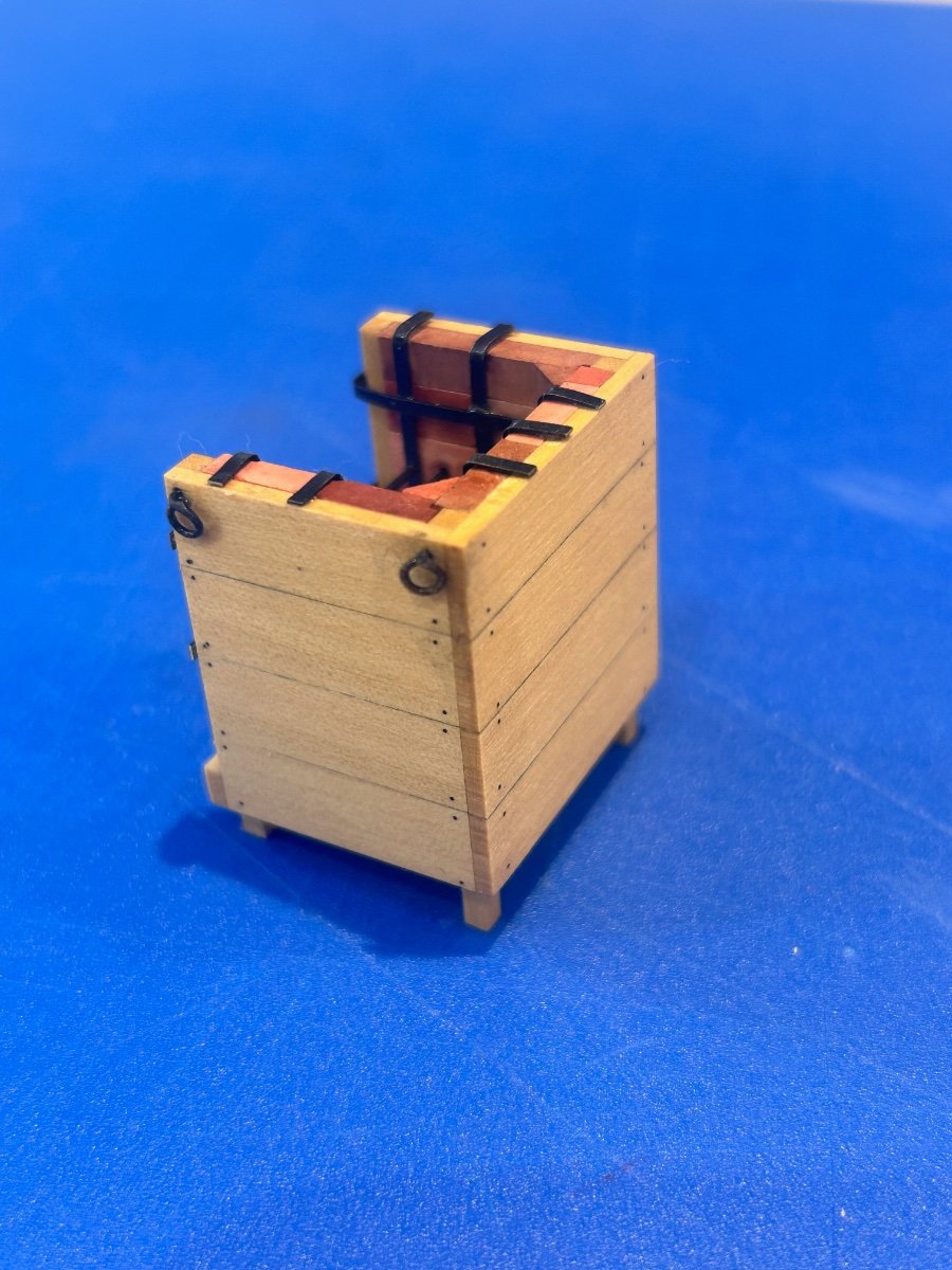
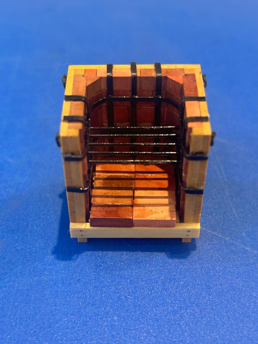
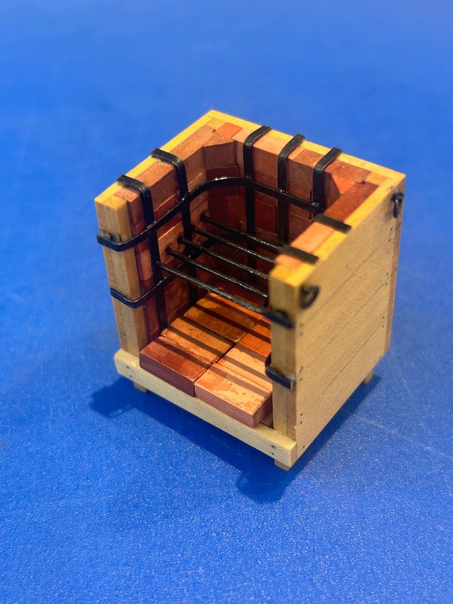
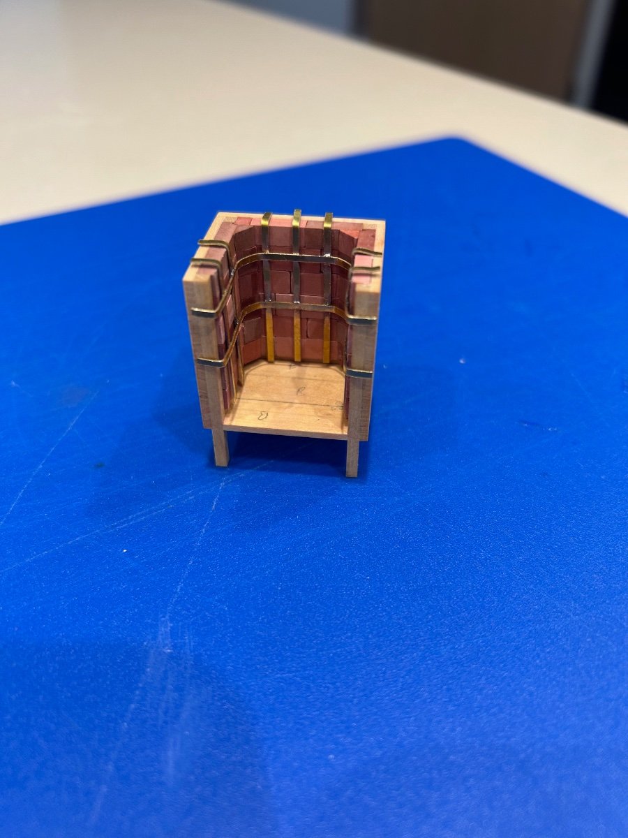
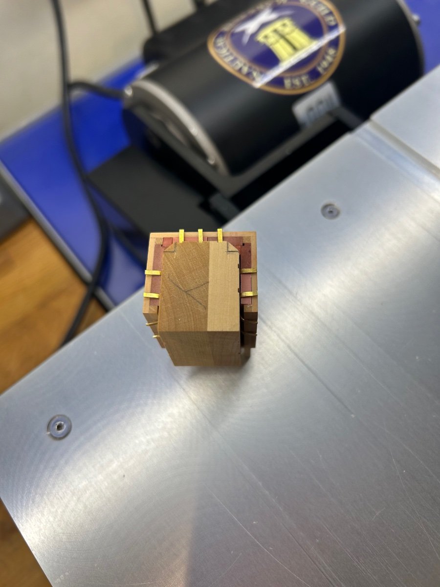
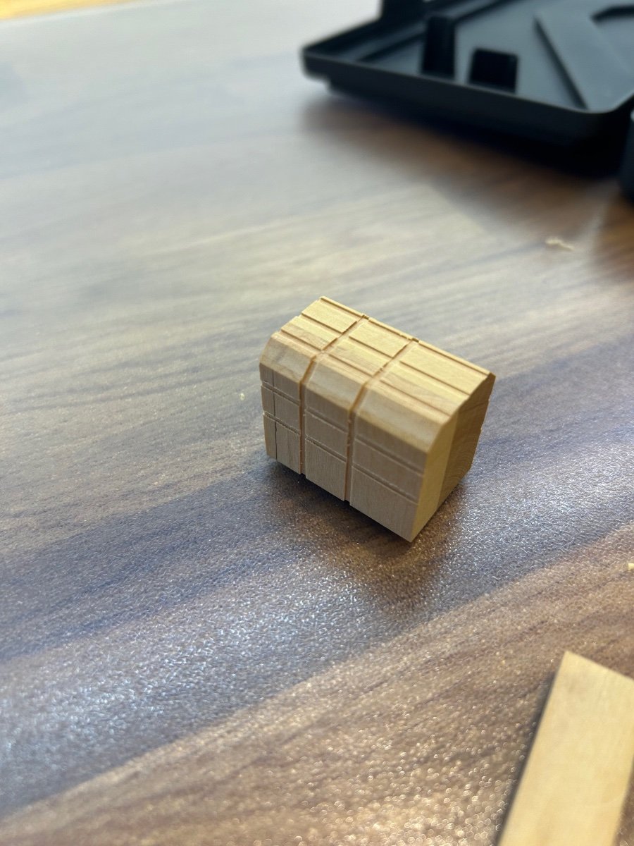
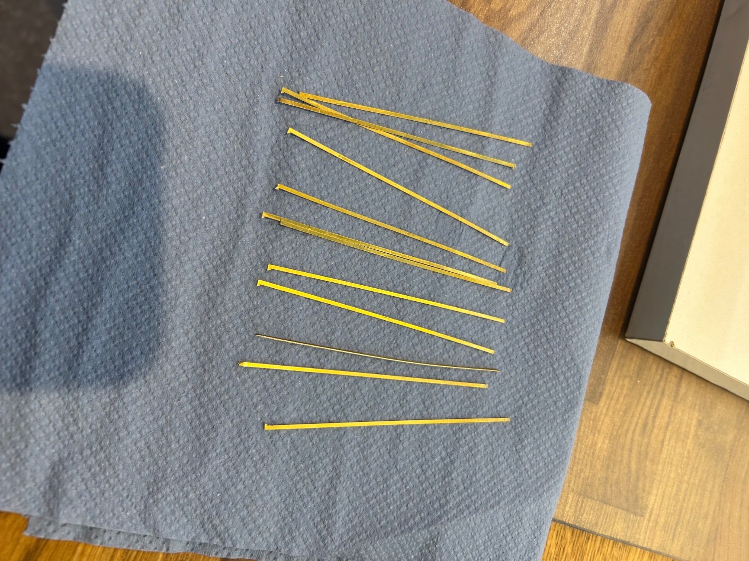
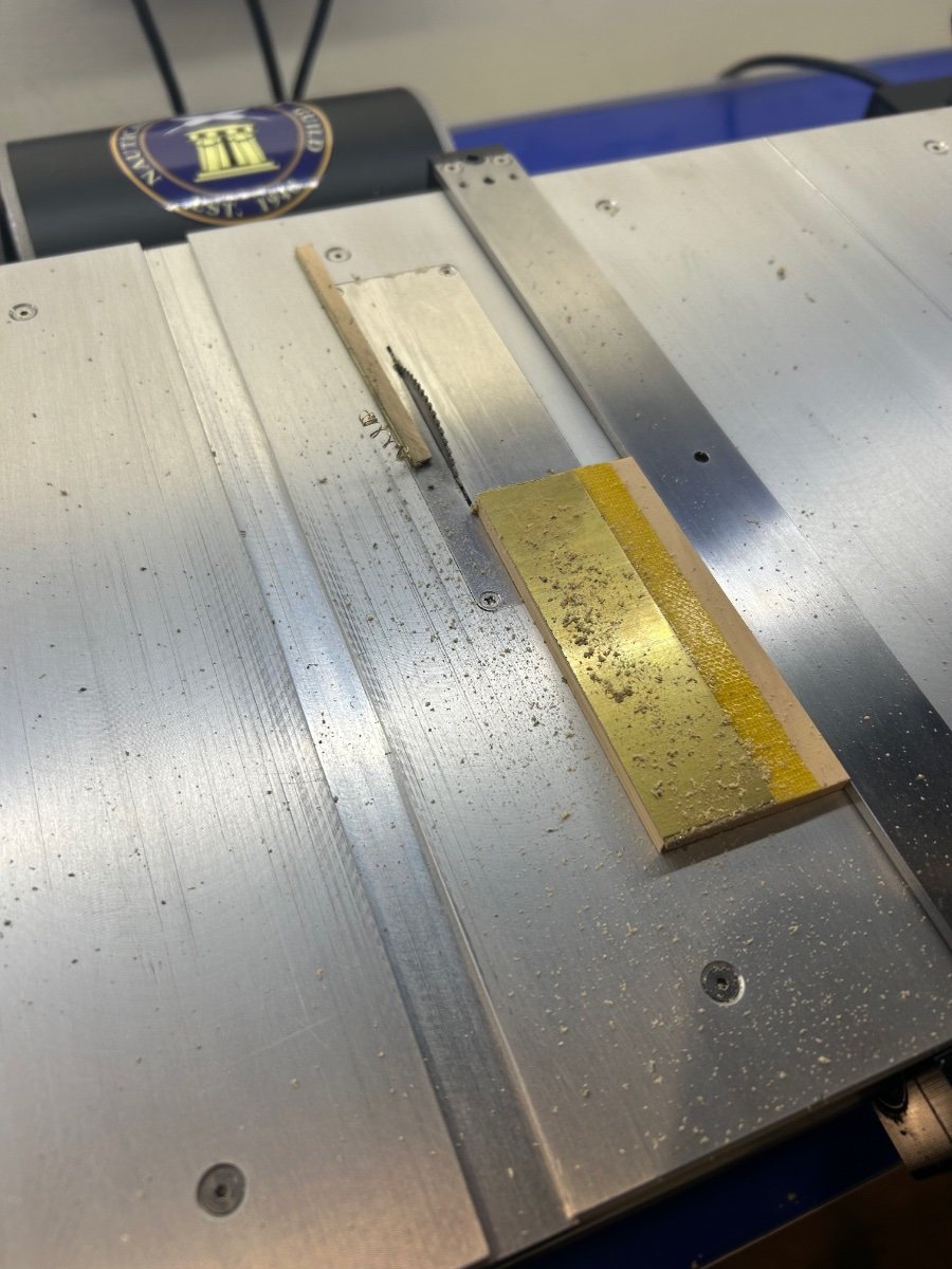
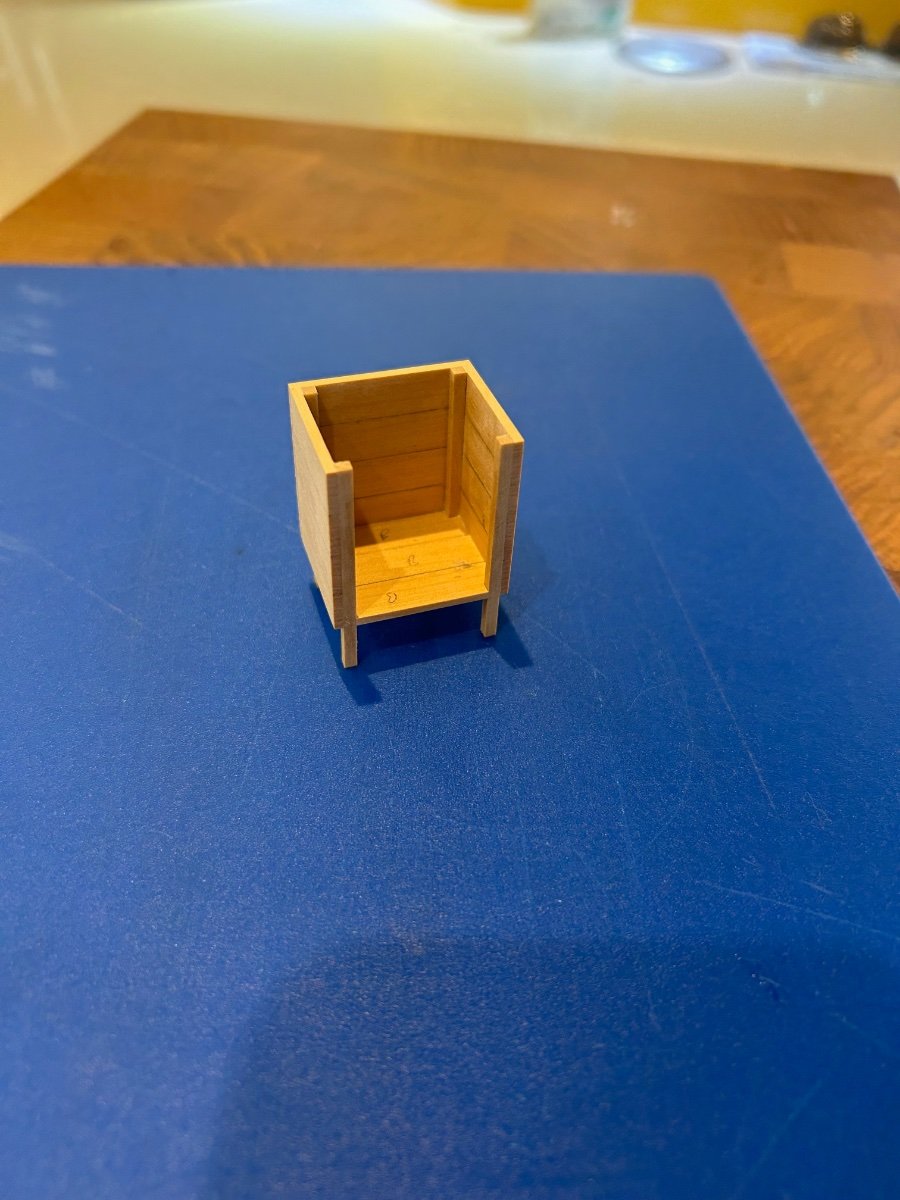
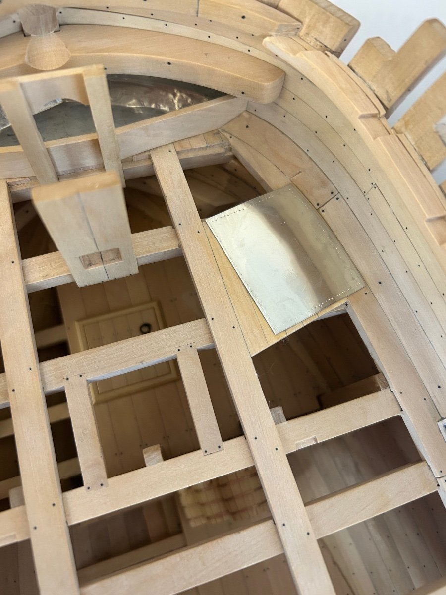
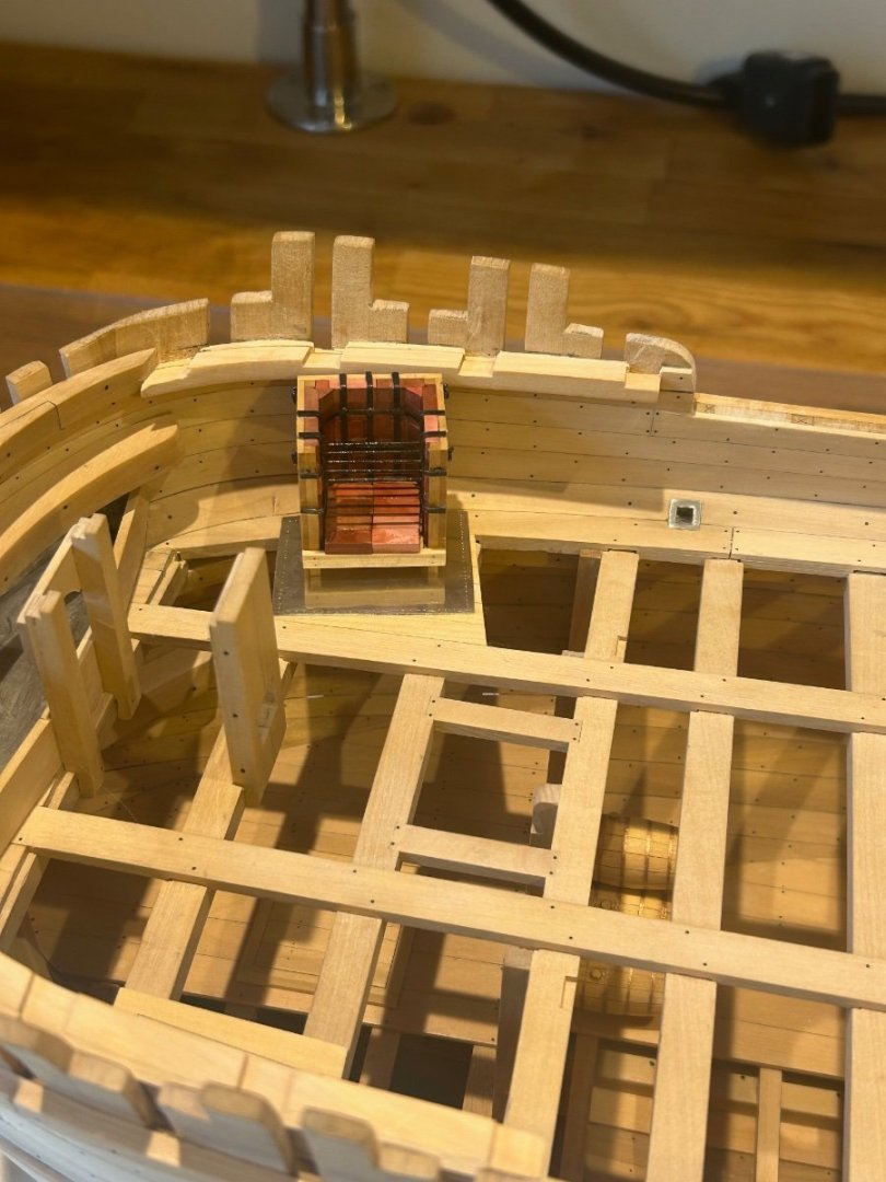
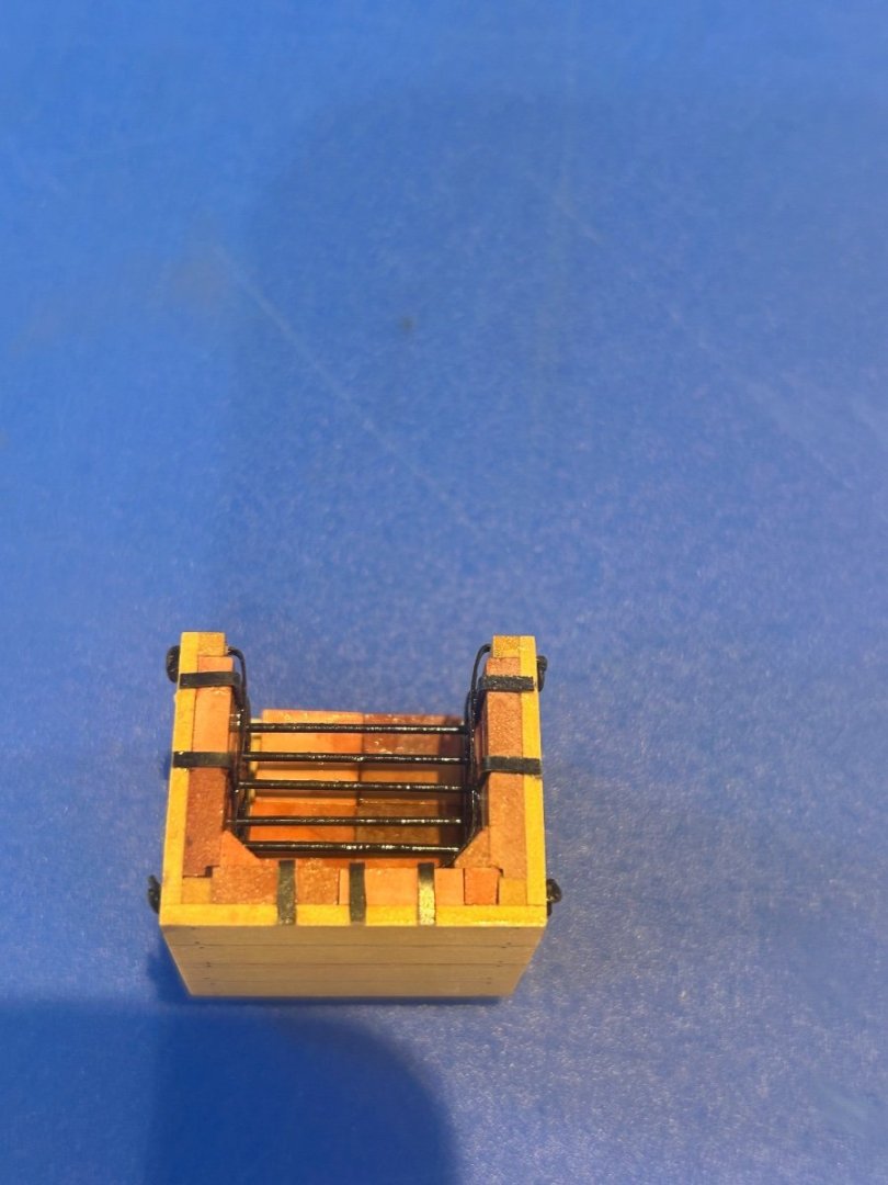
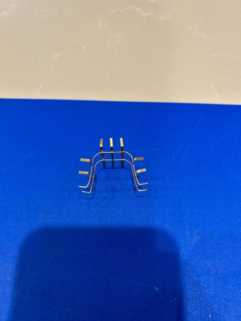
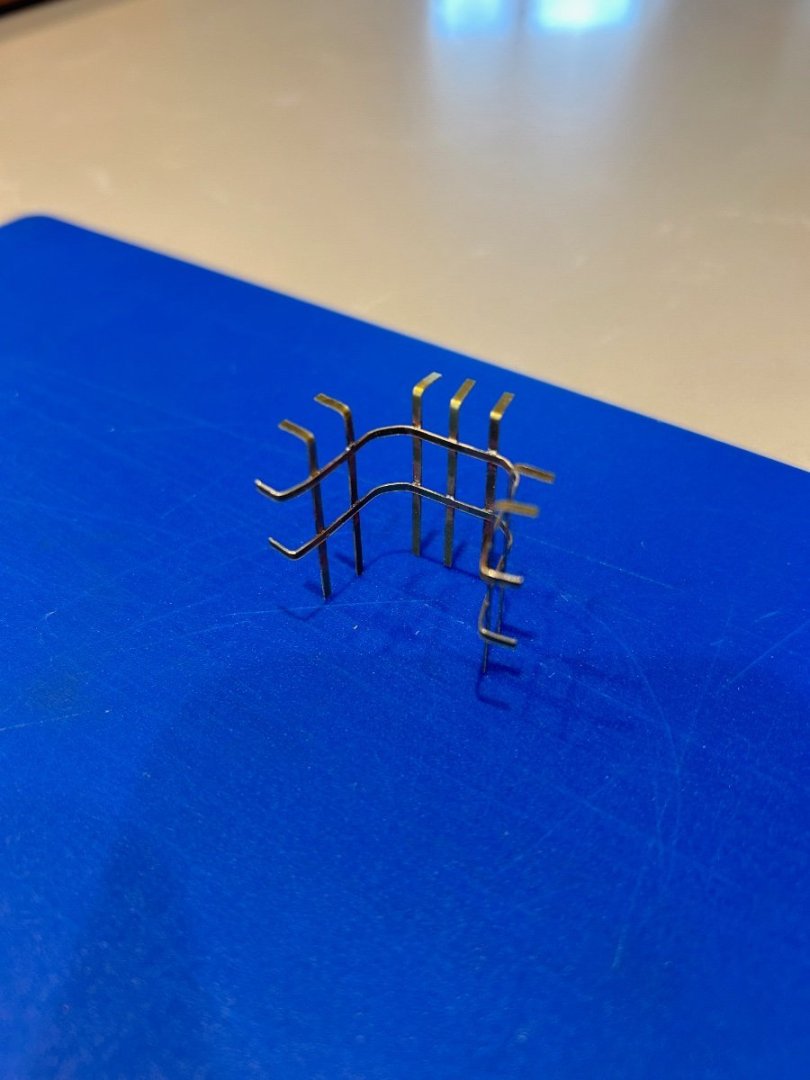
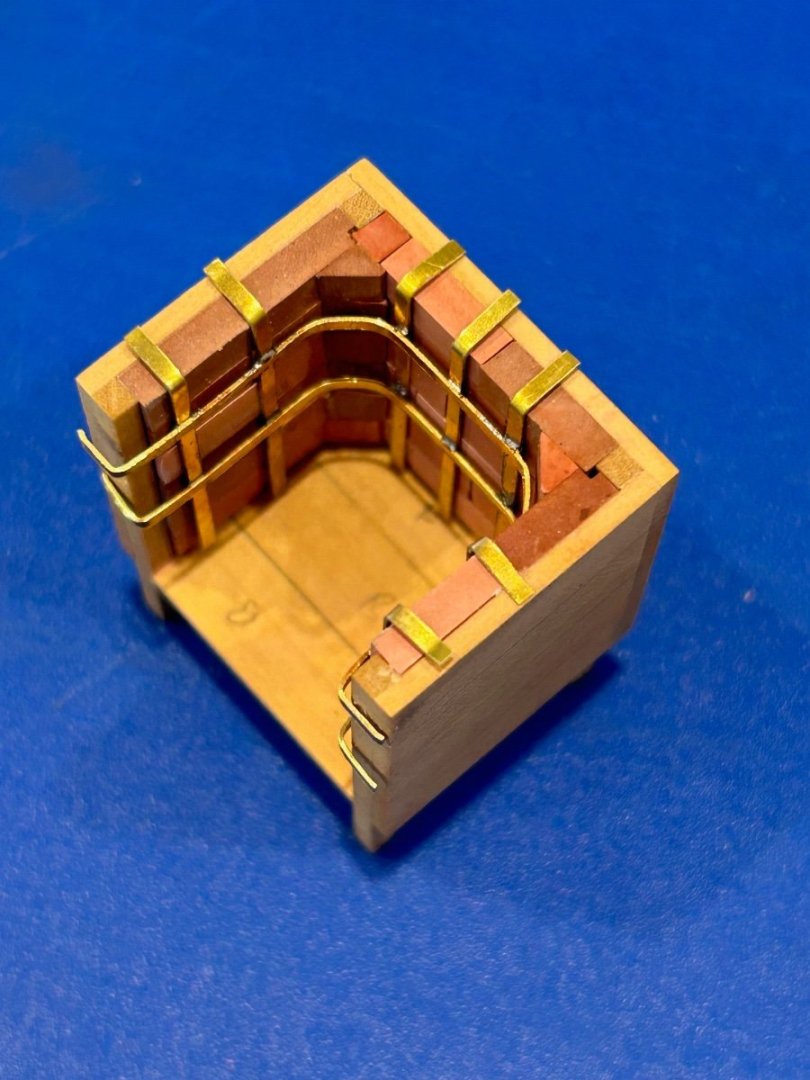
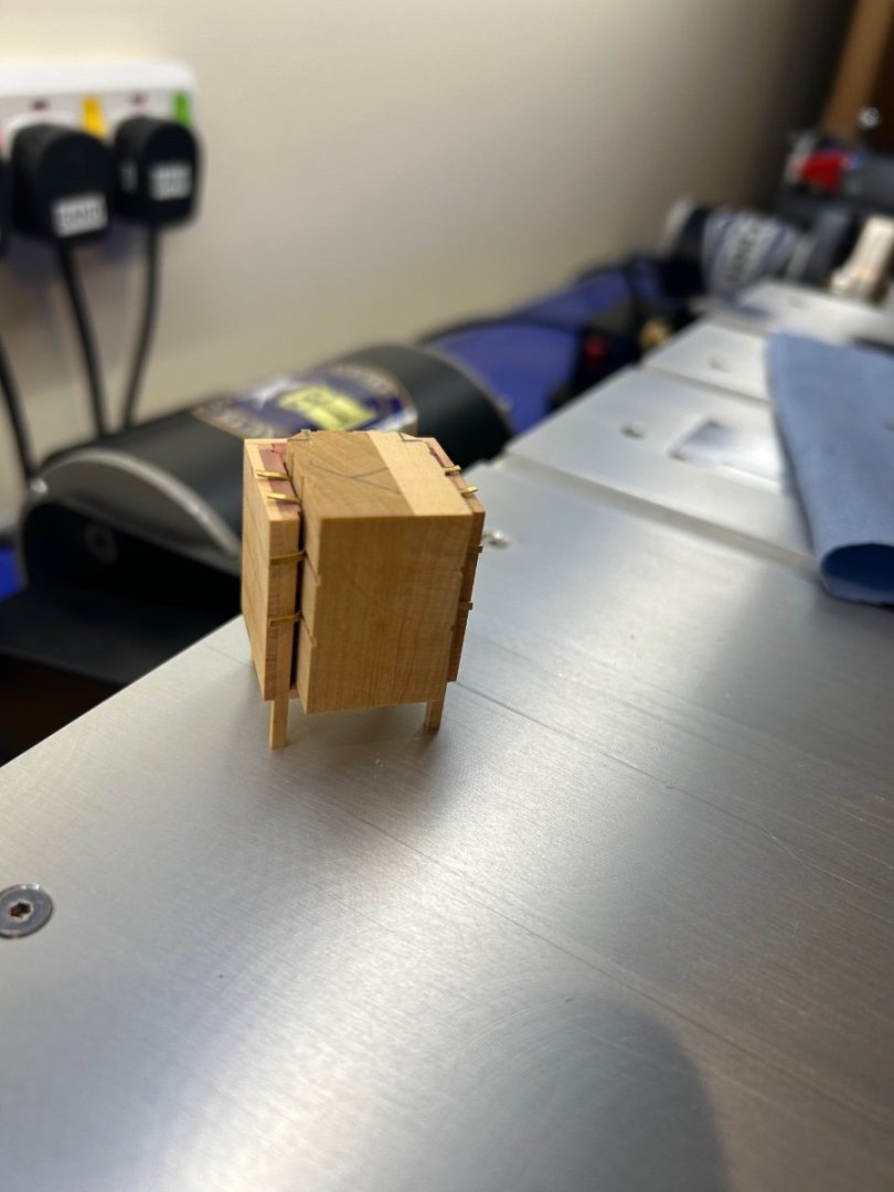
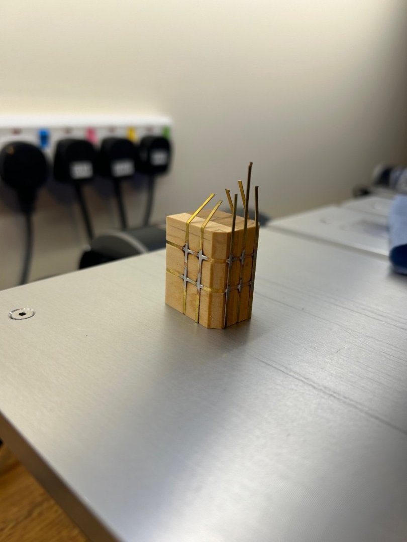
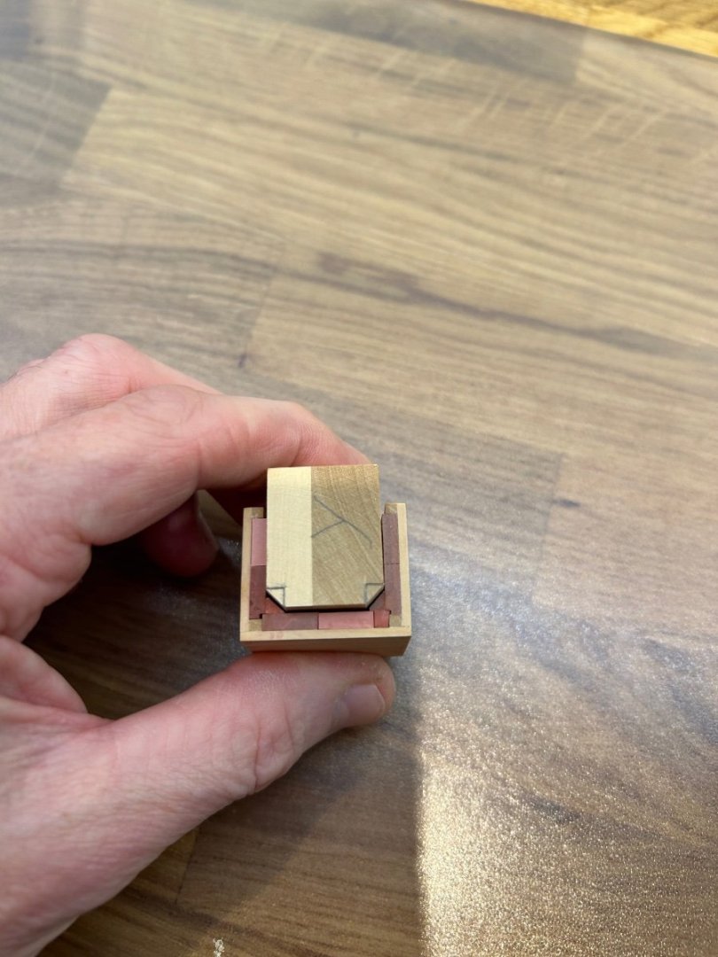
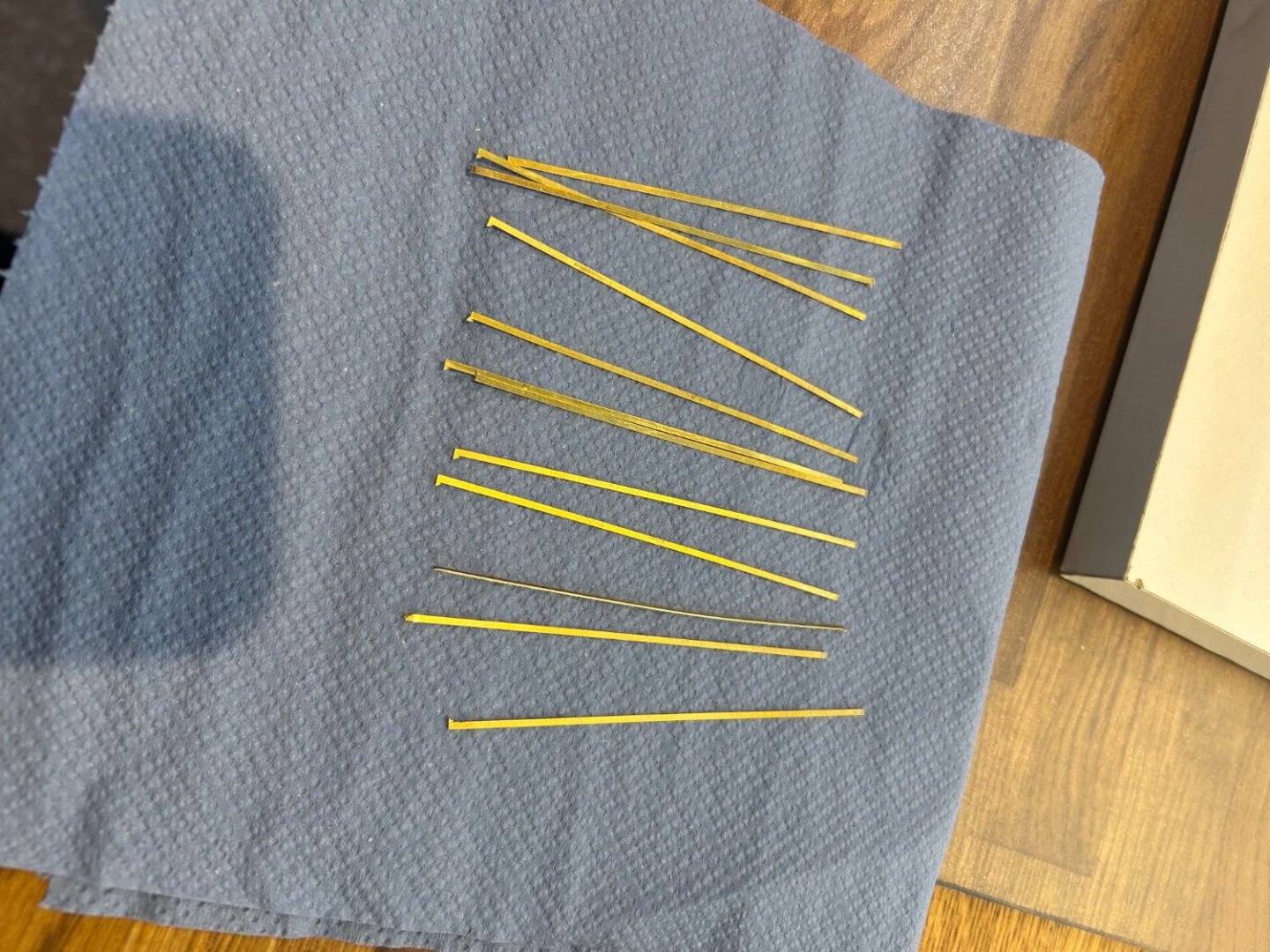
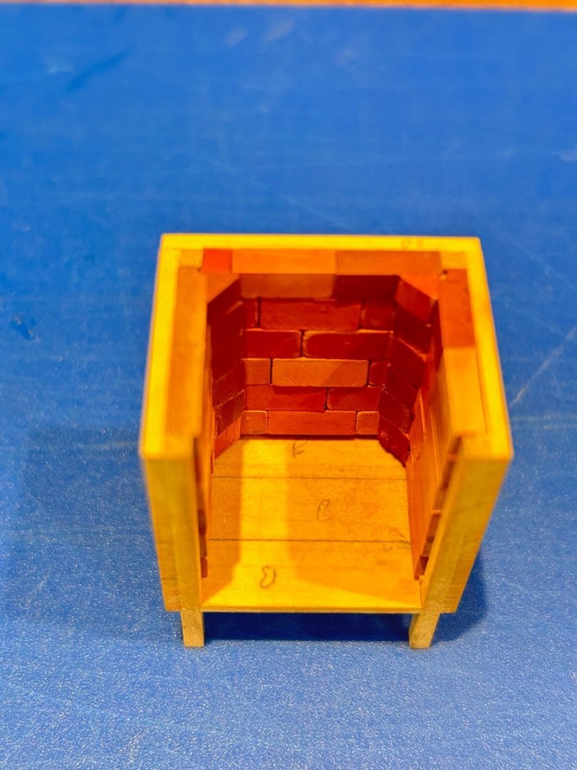
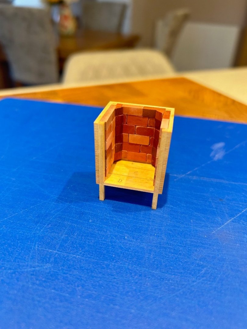
Thanks Jeremy 🙂 Right I'm back from the hospital and I've been repaired but apparently it's no work for me for a few weeks. So completely ignoring their requests I decided to get on with a bit of ship building to keep me sane 😜 Picking up where I left off my next jobs are to make the ships stove and the small office. Both of these parts require a bit of deck for a base so I did this first. I made these parts of the deck as they should be underneath them rather than just placing a bit of wood for them to stand on. The deck under the stove has a layer of metal on top I guess to keep the heat away from the wood. The stove starts with a pretty simple wooden box with 4 legs that go through the base. I then lined 3 of sides with bricks that I bought online at 1/24 scale - I never realised that building ships also involves brick laying! The only tricky part of this job was the small corner 45 degree bricks. To get the 12 that I needed cost me about 40 bricks! I never really know how much detail people want but next I needed to cut the brass strips for the iron cage that fits inside. These strips were cut from 0.25mm thick brass and are 1.2mm wide. To do this I use double sided tape to hold the brass on a sacrificial piece of wood. It's dead simple but the clean up of the saw takes about 30 minutes as the sawn tape just sticks to everything inside of it. I wanted the cage to be half decent so I opted to use a plug to try and get a good fit. It's a nice snug fit inside which does not allow for the brass cage. I then marked out and milled the cage to be made - The inside cuts are 0.5mm deep and the outside cuts are 0.25mm deep. It's not perfect but it's good enough. Next was to solder the pre-cut brass strips into the plug. This can then be pushed into place and the brass can be easily folded over the edges of the stove without loosing any of its intended shape. The result turned out quite nice Finally the brass was blackened; the bottom bricks installed; the feet cut to a 5 degree angle to suit the deck; lifting eyes made and my favourite - the grill bars were installed. I've not explained how the grill bars were fitted as this caused me some thinking as they are sunk into the bricks - so how do you think this was done?? I'm very pleased with this little stove which I guess took 10 - 12 hours to make as there are many elements to its construction. It's a bit glossy on the inside at the moment but I'll sort that out before it's finally installed. I have 2 more parts to make for it which help firmly fix it to the deck. Other than that I'll make a start on the small office next. Cheers Mark


-
I agree with barkeater the wood database is great https://www.wood-database.com/ The list that you have also gives sizes and quantity which should help you identify the different species.
-
Yep I'm the same - I have two types of knife which are the Stanley for tough work and Swann Morton scalpel blades for everything else. There's no sharpening involved so I can just get on with the job at hand.
-
Welcome to MSW Peter 👍
-
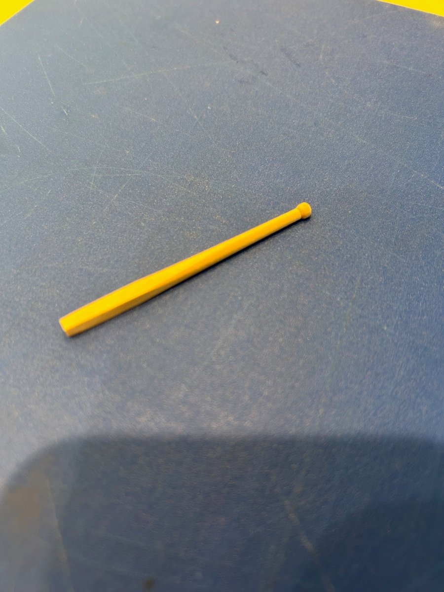
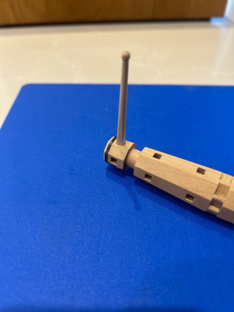
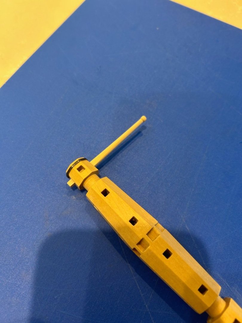
Ok last one from me! I couldn't resist making the lever for the windlass just to see how it looked. I haven't got a lathe so I winged it a bit but overall I'm happy with the result. I also like the way I can put it in any of the holes on the windlass. Sorry for the poor picture quality - Mark

-
Hi Mike - These are simply over priced 2 flute fish tail end mills that can be bought for a fraction of the price elsewhere. You are right though that they really are great for the job that we do and most importantly get the chips out quickly.
-
That is class work mate and the experience shines through
-
I agree - wow mate that is seriously impressive work and needs to be seen
-
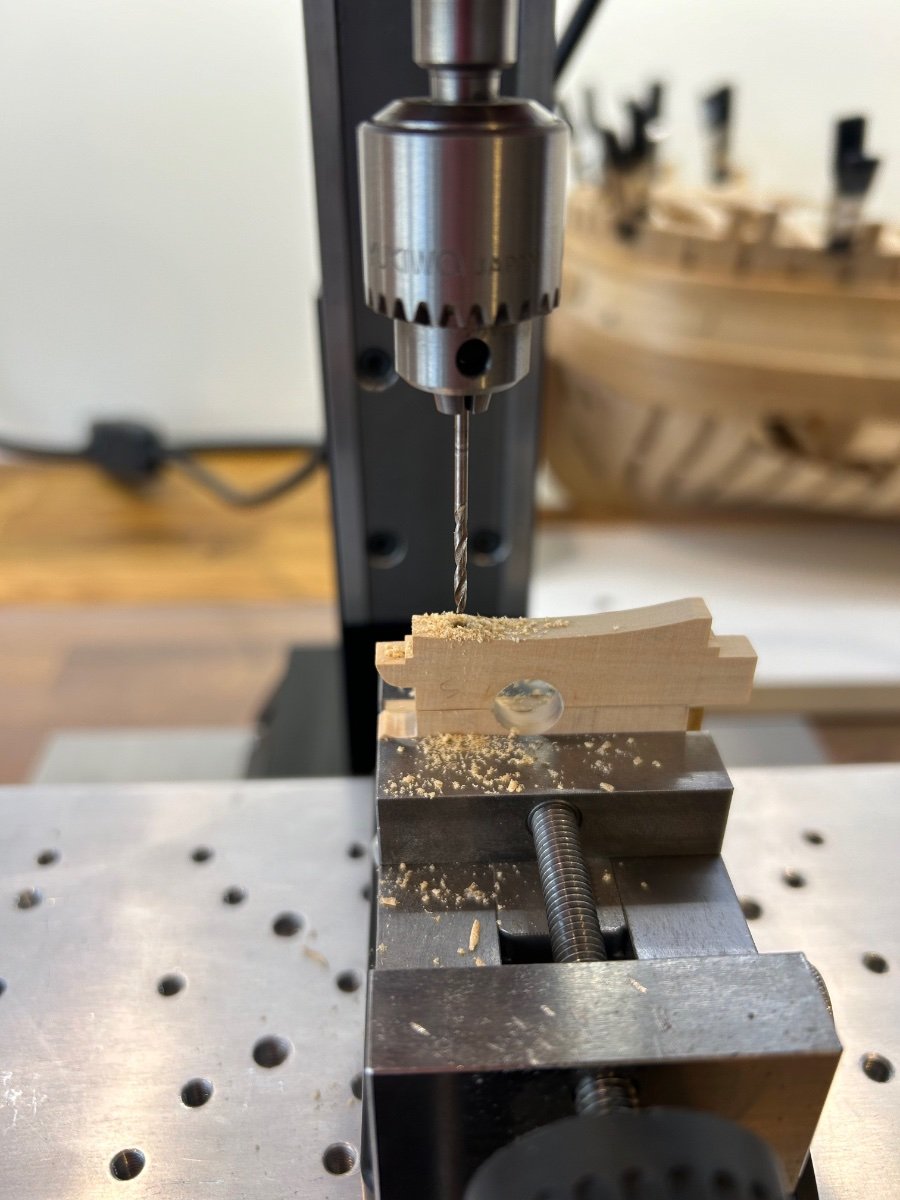
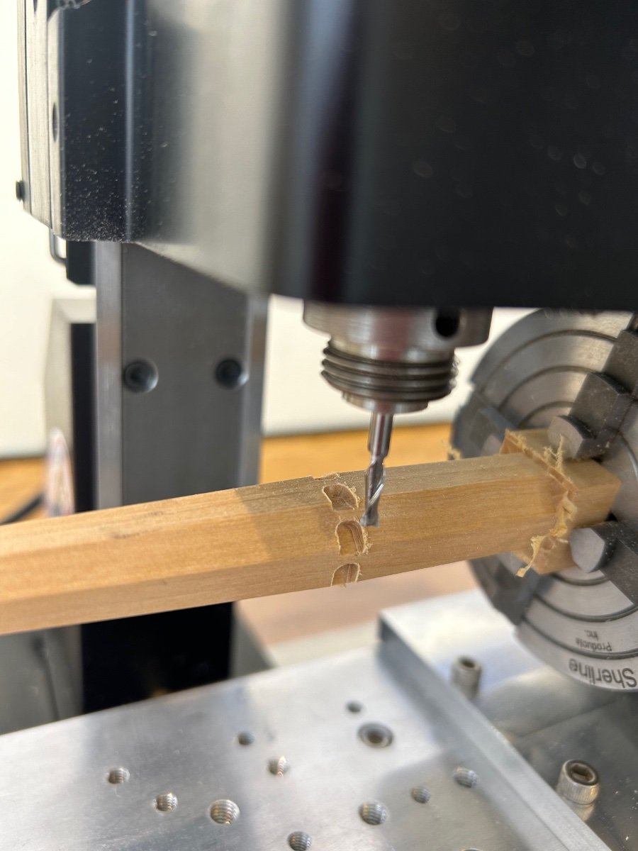
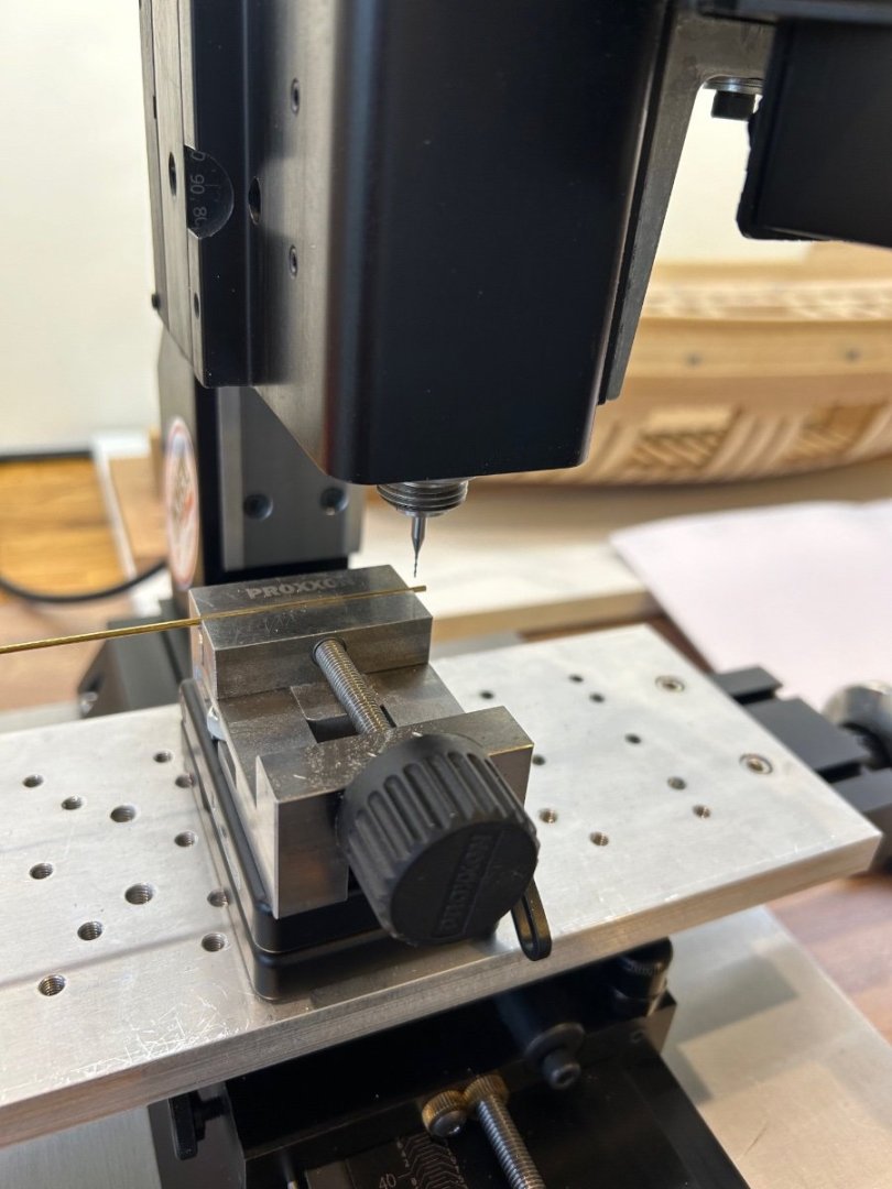
Hi Greg - thanks for the nice comment as I have always seen this part of the ship as one of its key features. Its still turns which is what I was aiming for and once the lever is in place I think it will look nicer. I did take a chance and guessed that the cheek sat on top of the planking to allow for any maintenance but I could be wrong. You are spot on about drilling holes through round stock - I would also add that you need to have it as close to the vice or even better inside the vice to reduce vibration. Because I used an end mill it did the whole job in one operation but they are extremely fragile. If I was going smaller I would put a small flat on the stock using the end mill, then use a centre drill as you have suggested and finally use a drill.
-
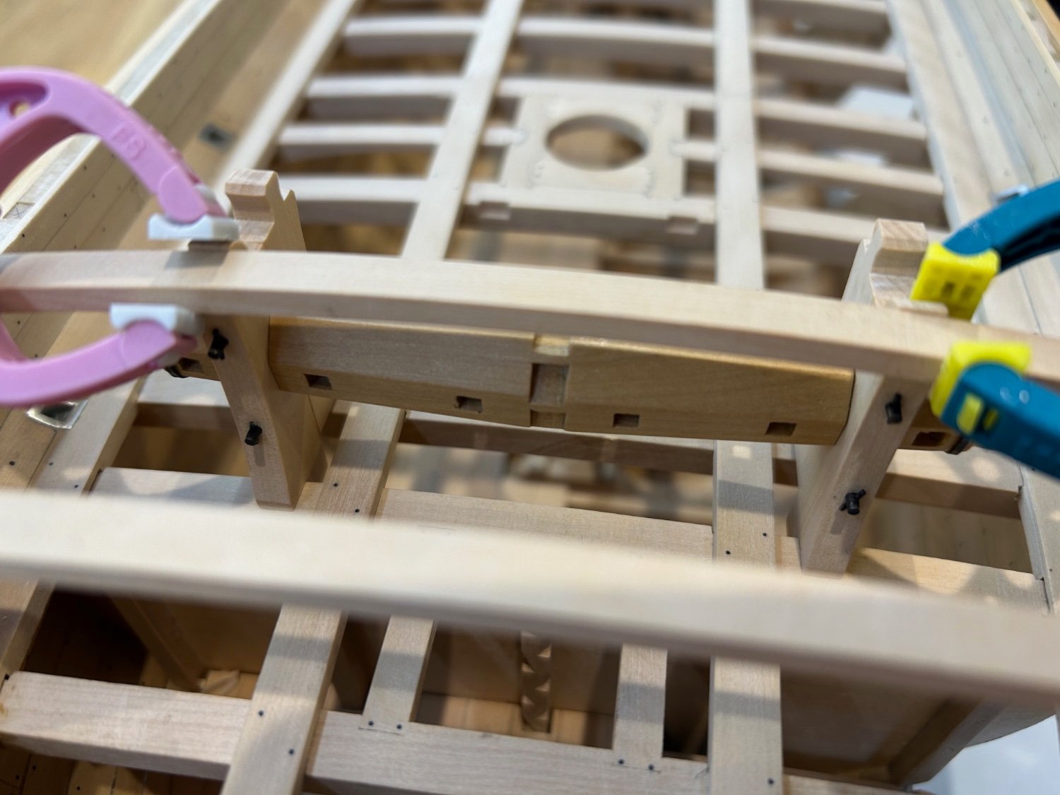
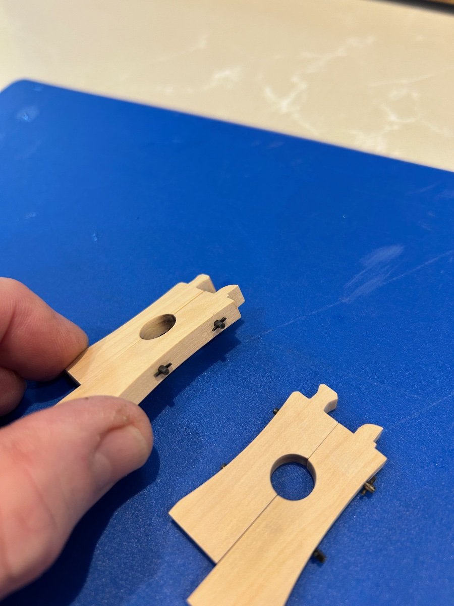
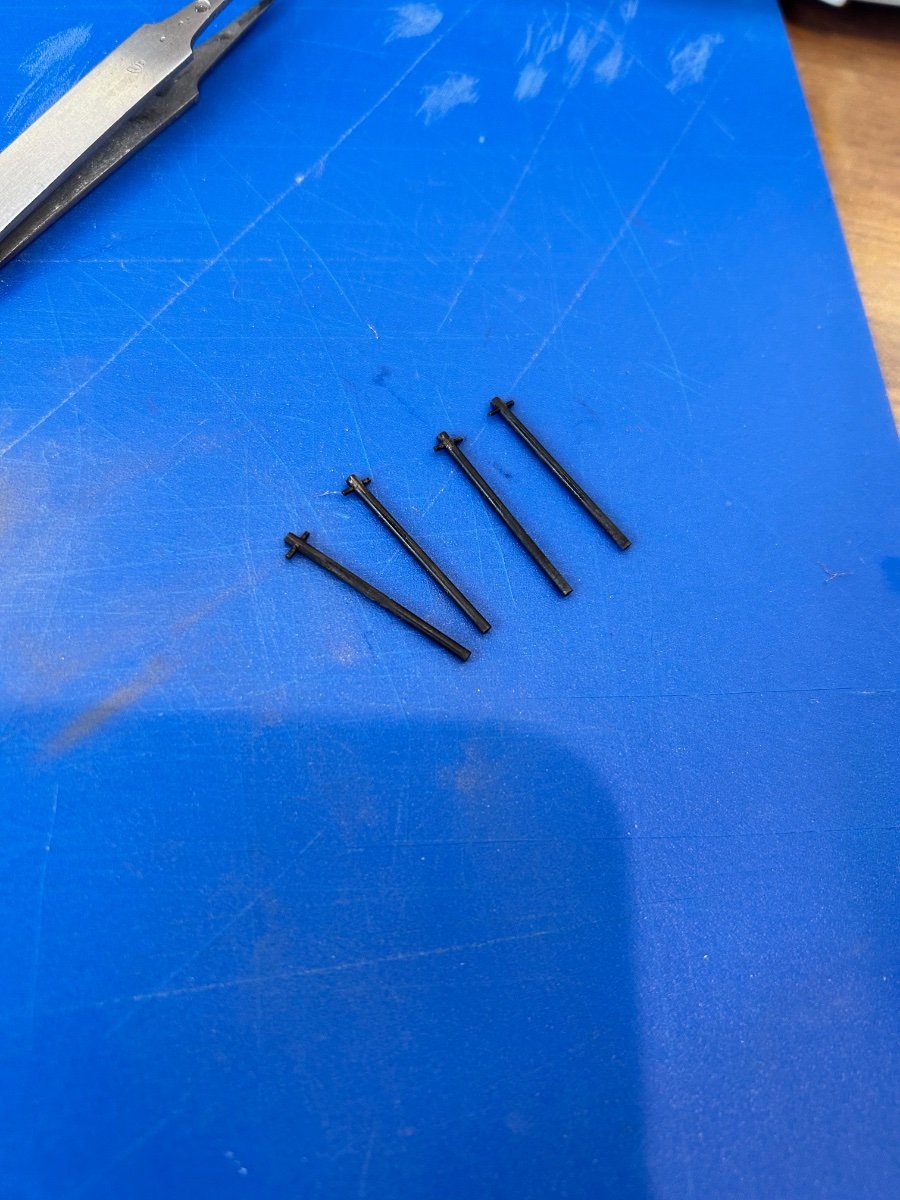
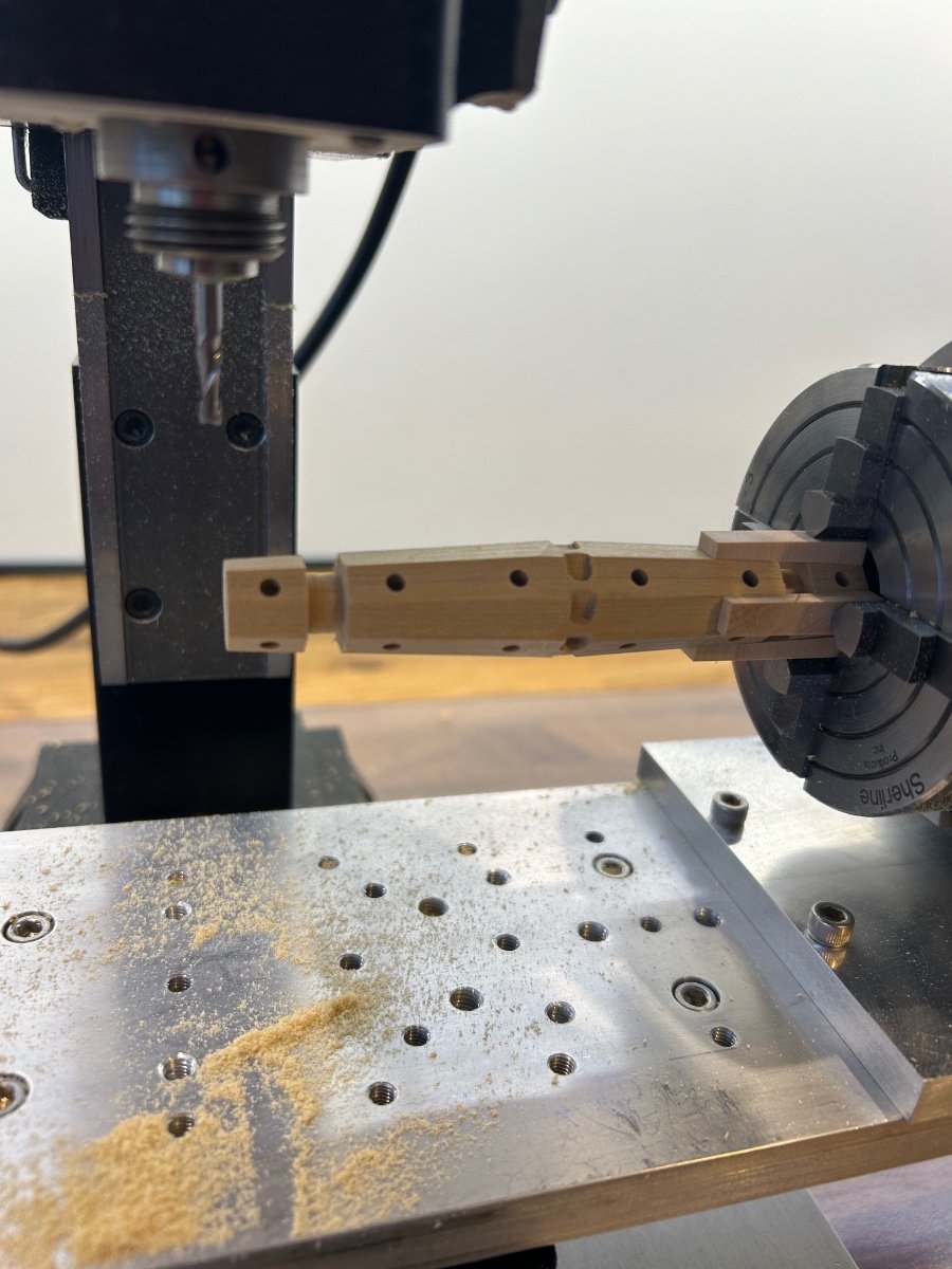
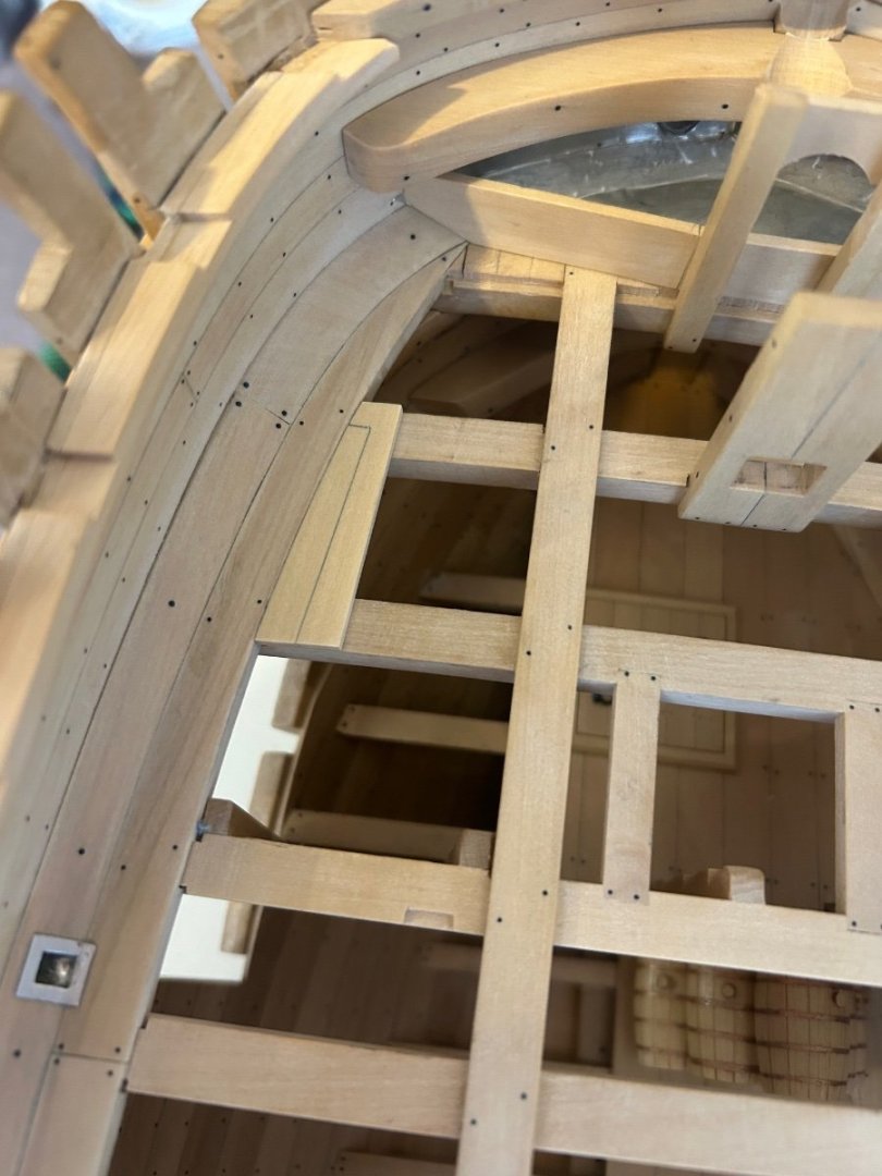
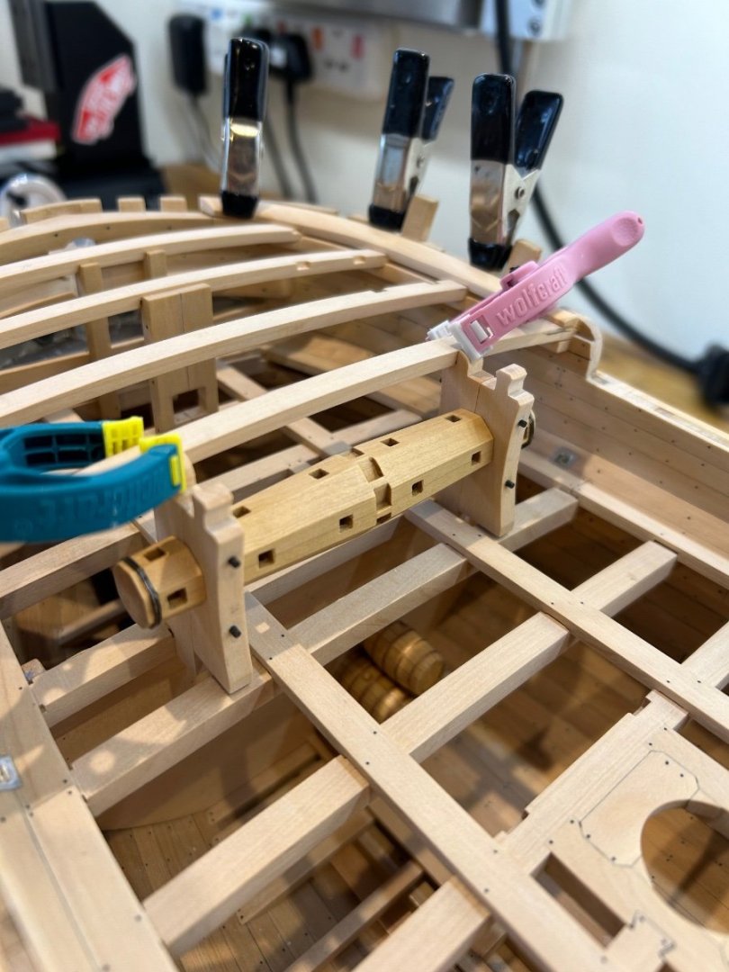
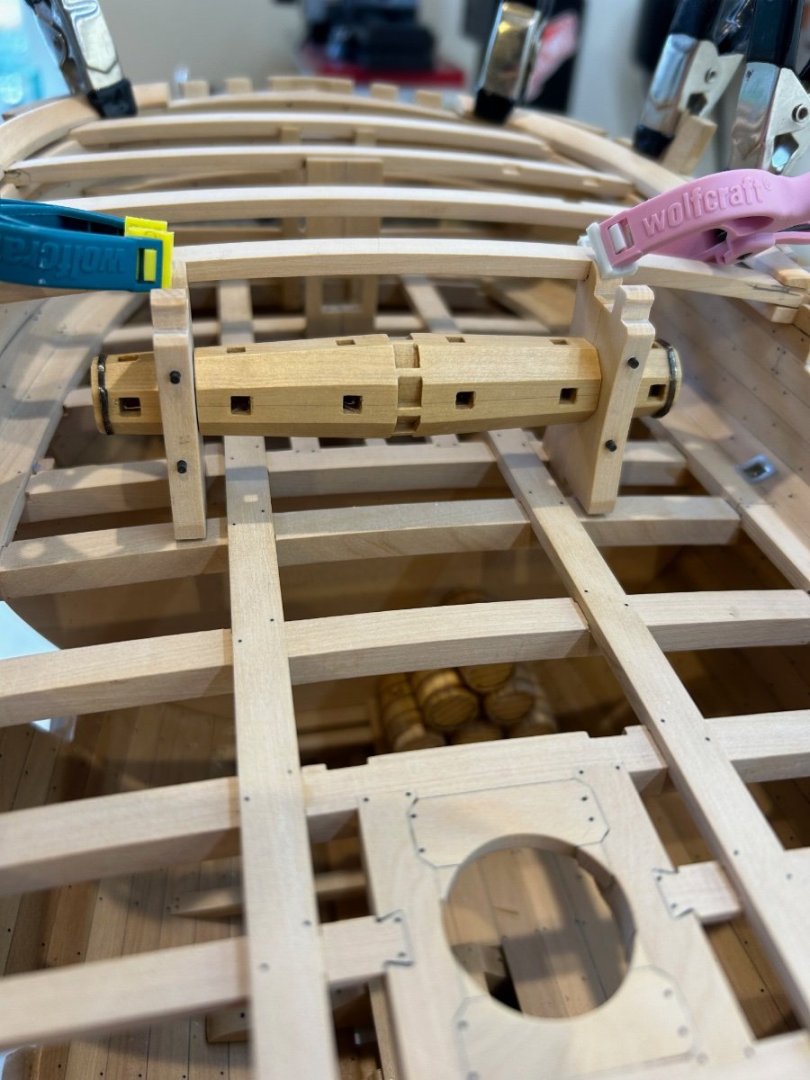
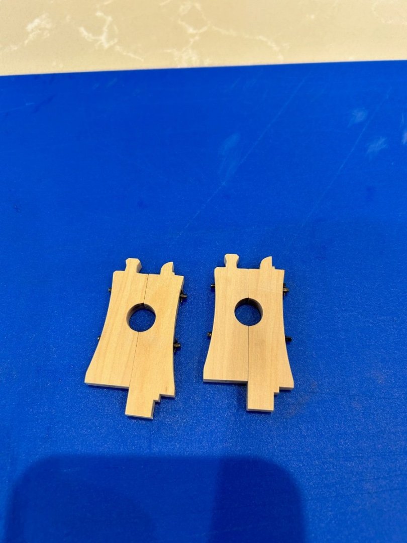
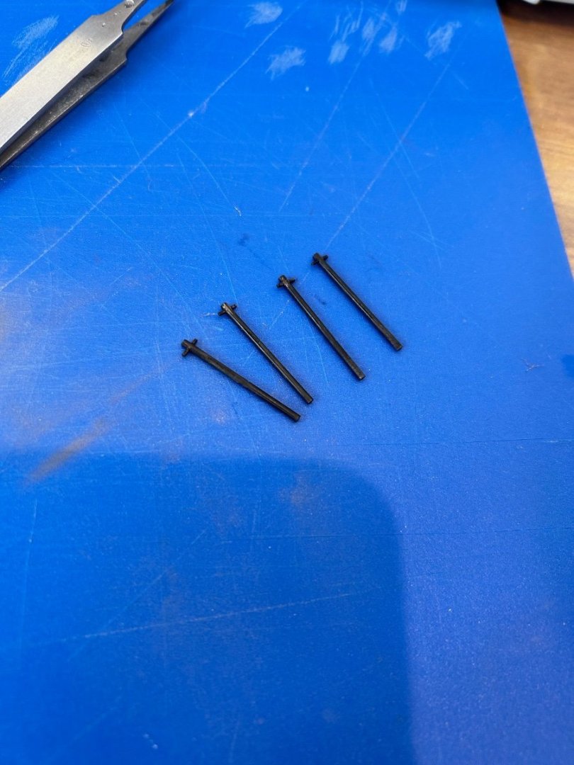
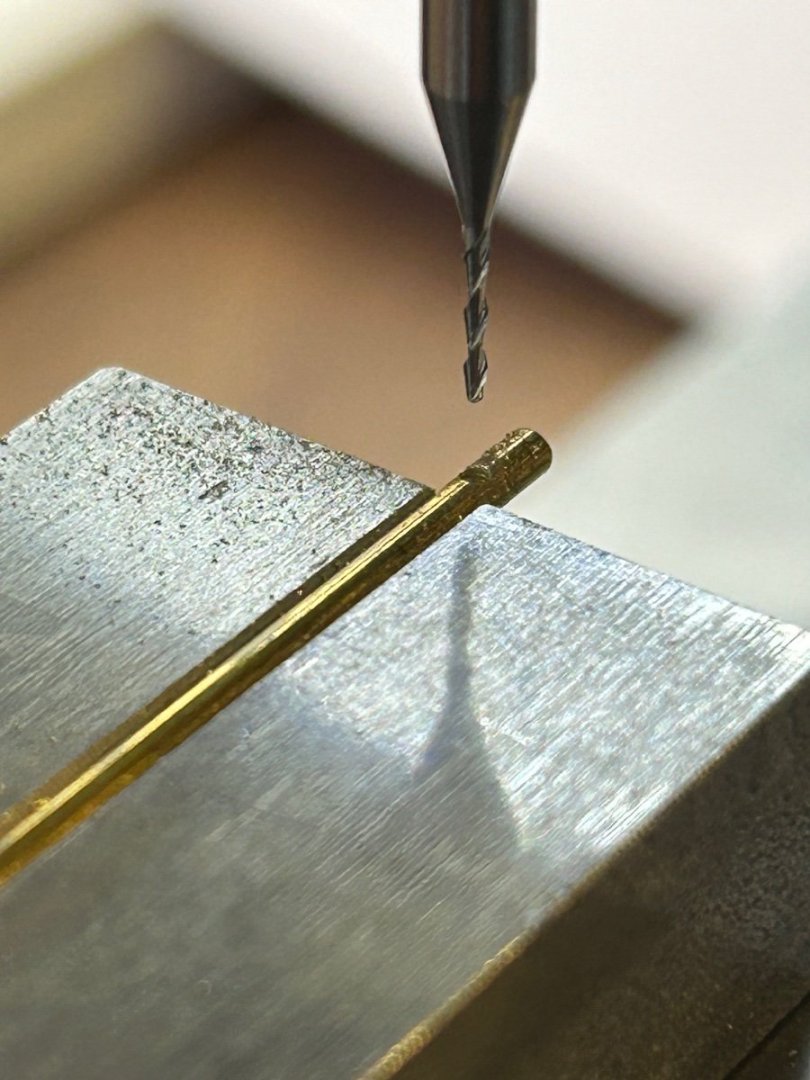
Some more work done on the windlass and this time I've made the Carrick piece (the larger part) and the cheek. But before I made them I wanted to make the big locking bolts that run completely through them. To do this I first had to drill a 0.68mm hole (the smallest end mill that I have) through a 1.5mm diameter brass rod. Here's a close up of the drilling which makes it look like I'm running a 6mm drill through a 10mm bar 😜 A bit of perspective These were the beginning of the bolts which were then cut to size and a tapered 0.8mm pin put through and soldered in place. I then chemically blacked them and here's the result. I haven't taken any pictures of the making of the Carrick piece or the cheek as it's very straight forward. I did however take one of the drilling of the holes for the bolts. I temporarily glued the two halves together and ran the drill straight through. This worked great and was very easy to do and once again a little IPA separated the parts. The finished parts with the bolts in place. Finally here are parts all dry fitted into the hull. Nothing is glued in at the minute including the beams but it all fits quite nicely. So thats it for a couple of weeks as I'm in for a quick surgery (nothing major) which they have told me will restrict my lifting and moving. As soon as I'm fit I'll be back on it. Cheers Mark


-
Hi Tobias - get a square brass tube and place it over the round hole. Give it a tap with a hammer and you get a perfect square outline to work from. After that it’s just careful use of chisels and files.
-
AON thanks for that information - even better I've just been on Amazon and got a used copy of that book for £10!
-
La Palme by Tobias - 1:36 - POF
Some Idea replied to Tobias's topic in - Build logs for subjects built 1501 - 1750
Beautiful work Tobias - your stern looks very symmetrical which is so difficult to do - just fantastic 👍 -
Thanks wefalck that’s very helpful. I have always painted brass before but the blackening process is so much easier and looks so much better too.
-
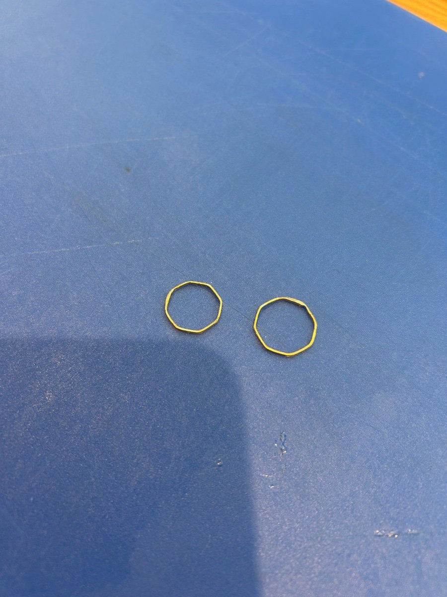
Hi - Now firstly excuse my limited knowledge on this subject as I only used brass blackener for the first time this week. I blackened 2 brass rings that were soft soldered together at their joint. I was pleasantly surprised to see that the solder had been blackened somewhat too. Would liver of sulphur do the same thing? I was expecting to have to touch the solder up with matt paint but found this unnecessary. If it does I would like to just have an experiment with some pieces at home to see which gives me the best results.
-
I have used lead shot just as you have and it works great. The only difference that I did was to line to compartment with cling film first. I then put in the lead shot and poured in the resin. Once set I could lift the set shot out in one complete lump should I ever need to do any maintenance as it never was stuck to the hull.
- 57 replies
-
- 3
-

-
- Nordkap
- Billing Boats
- (and 1 more)
-
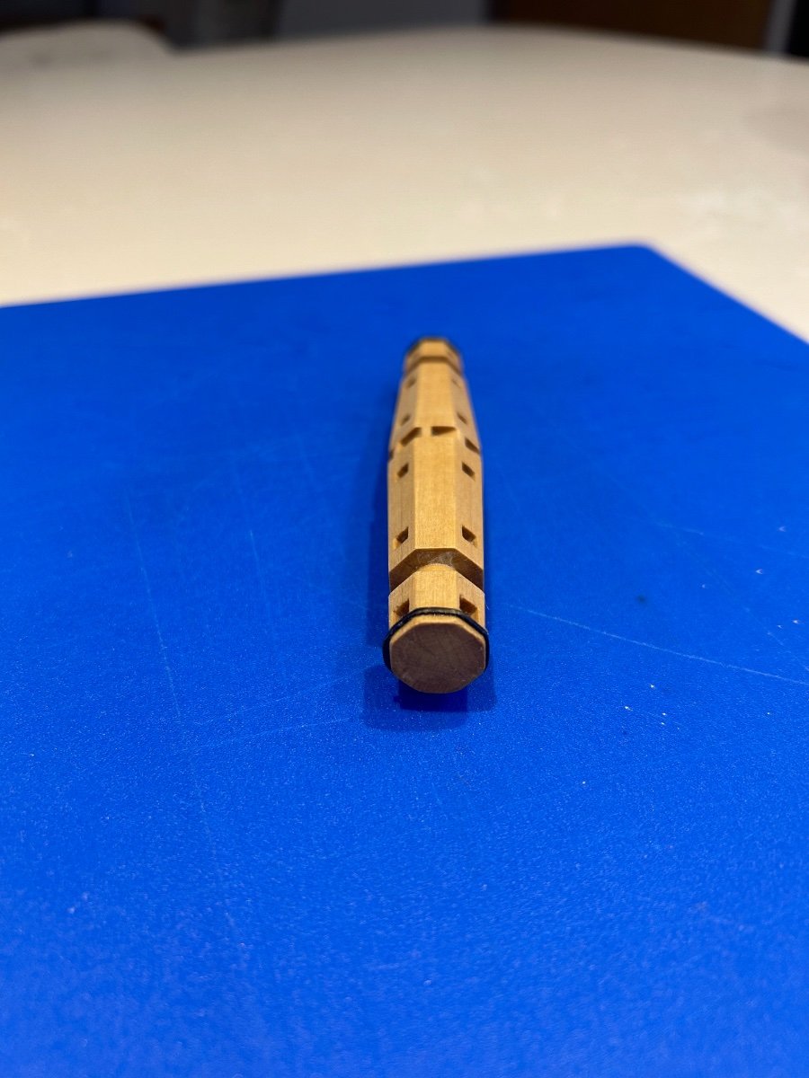
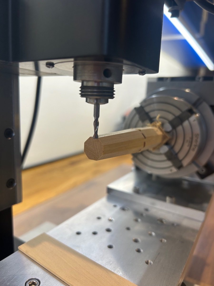
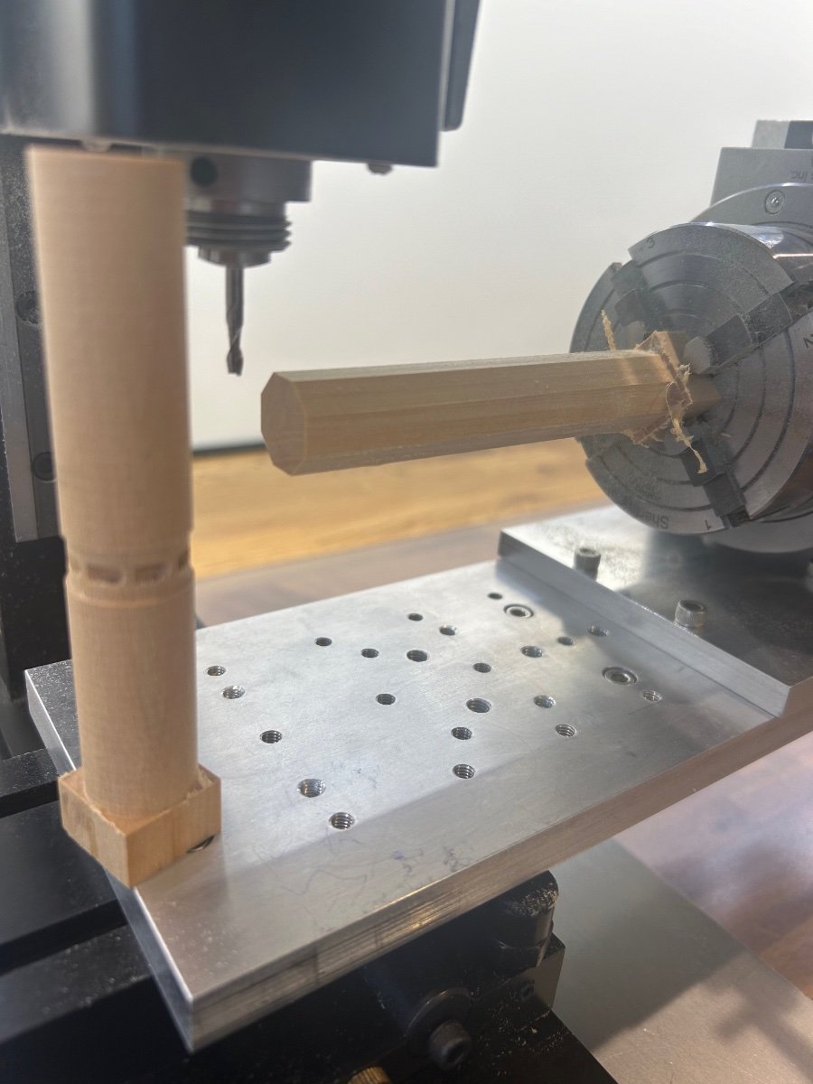
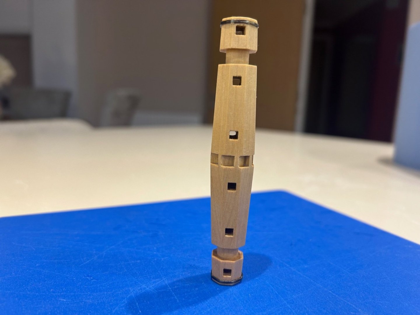
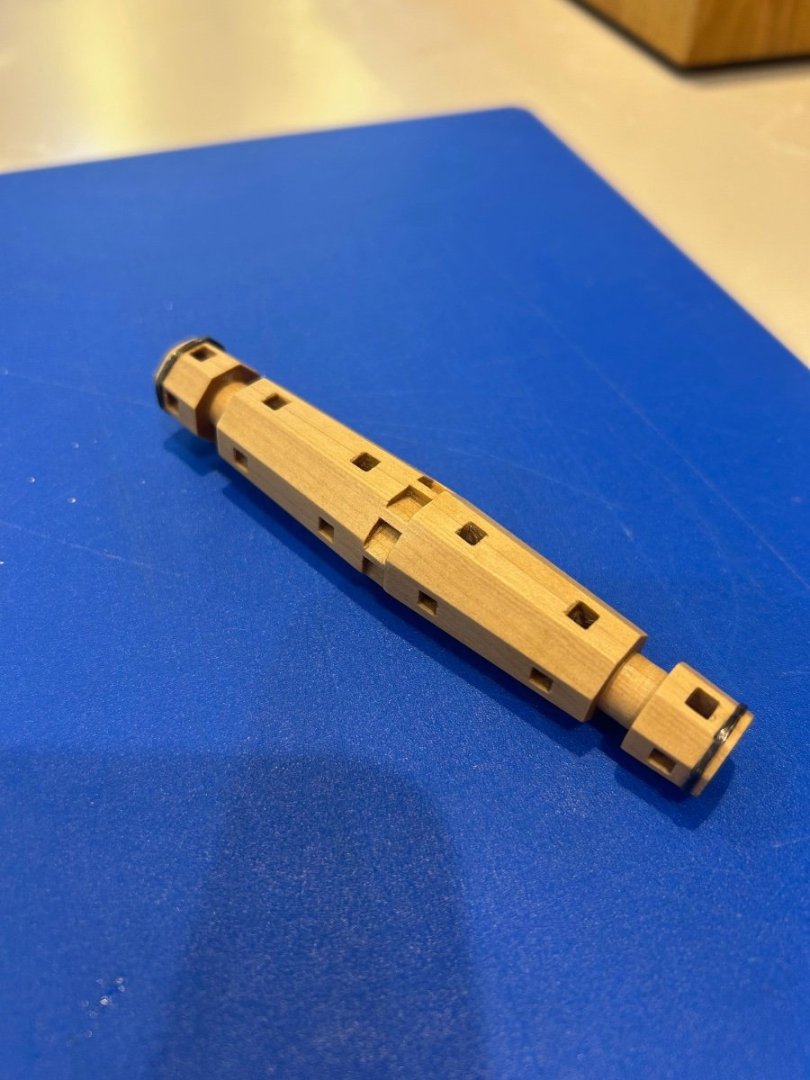
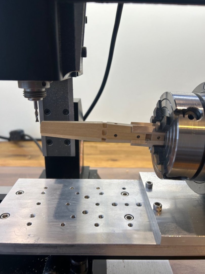
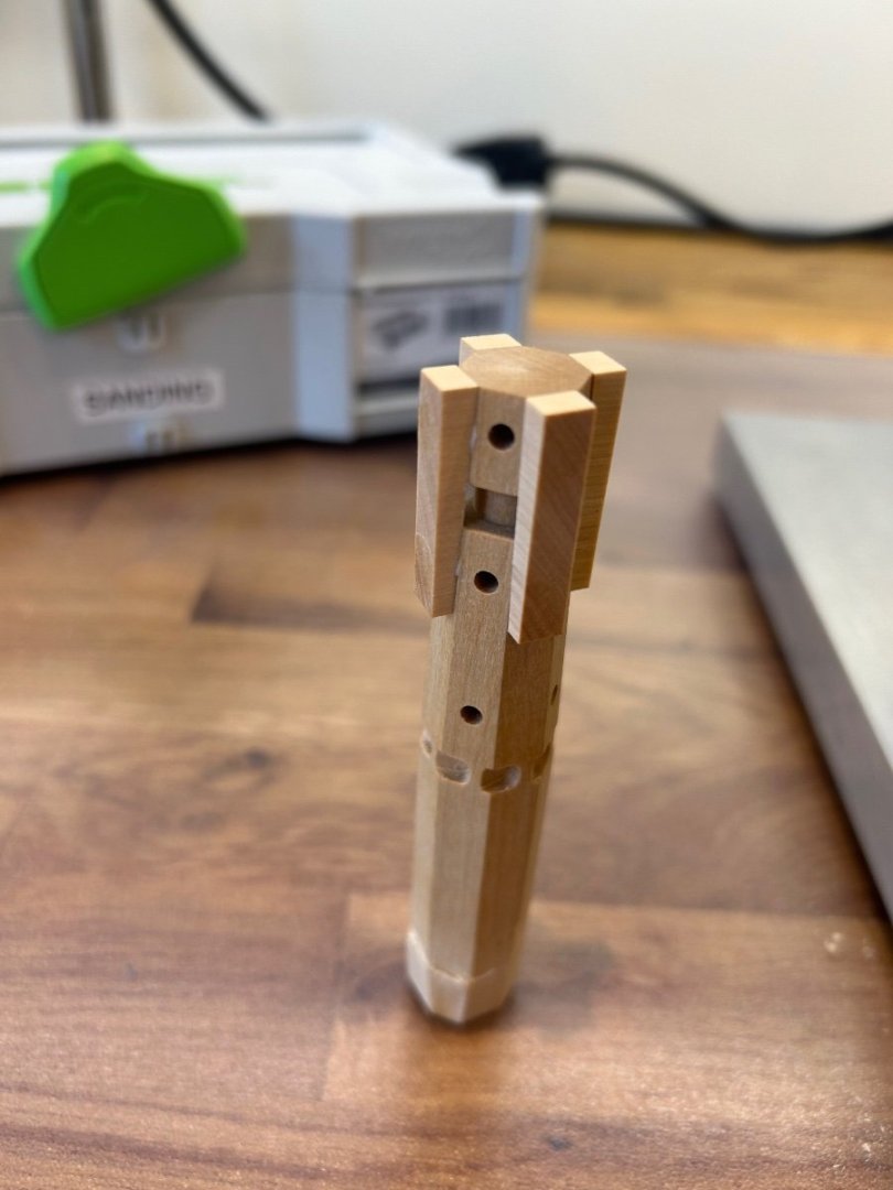
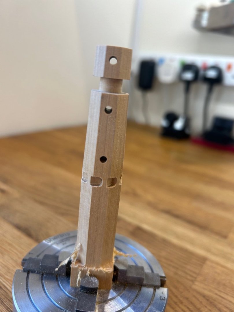
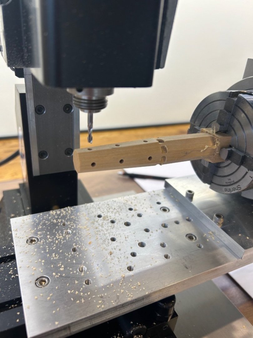
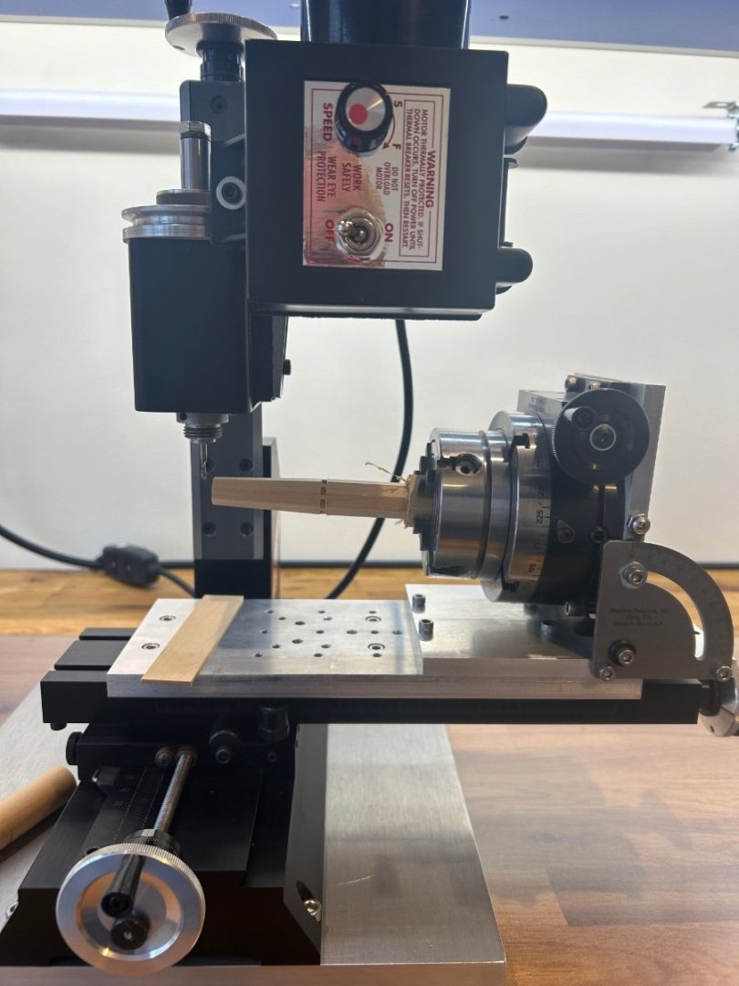
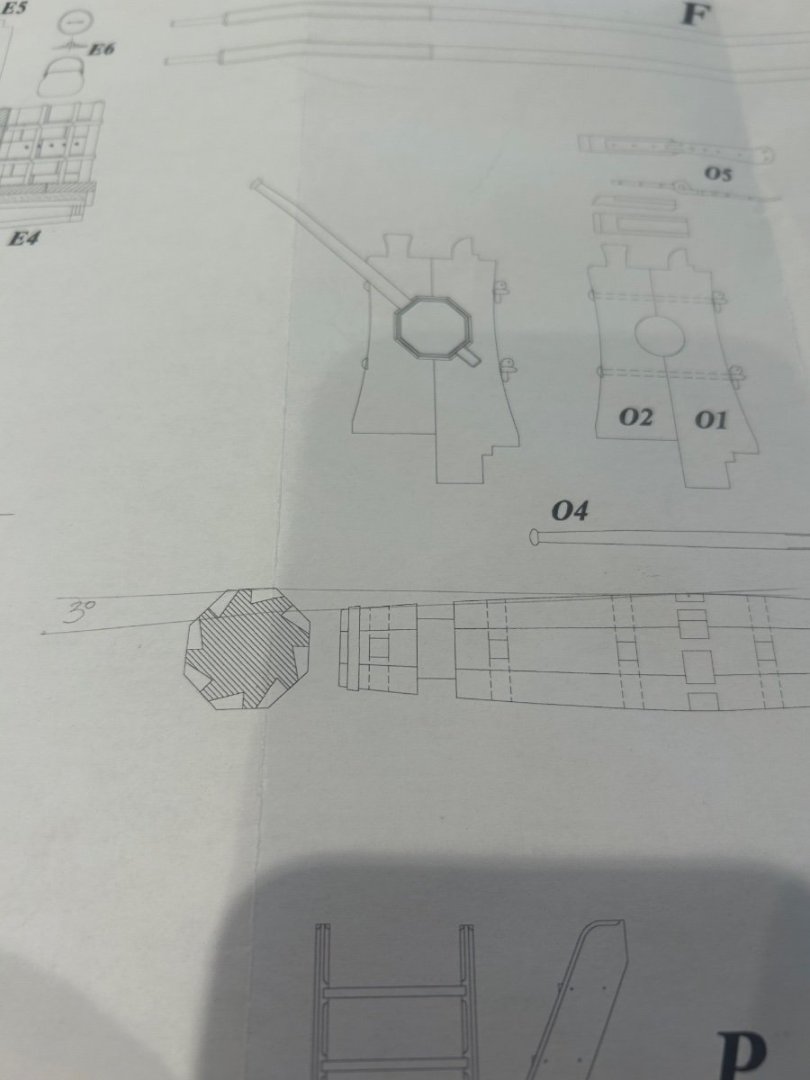
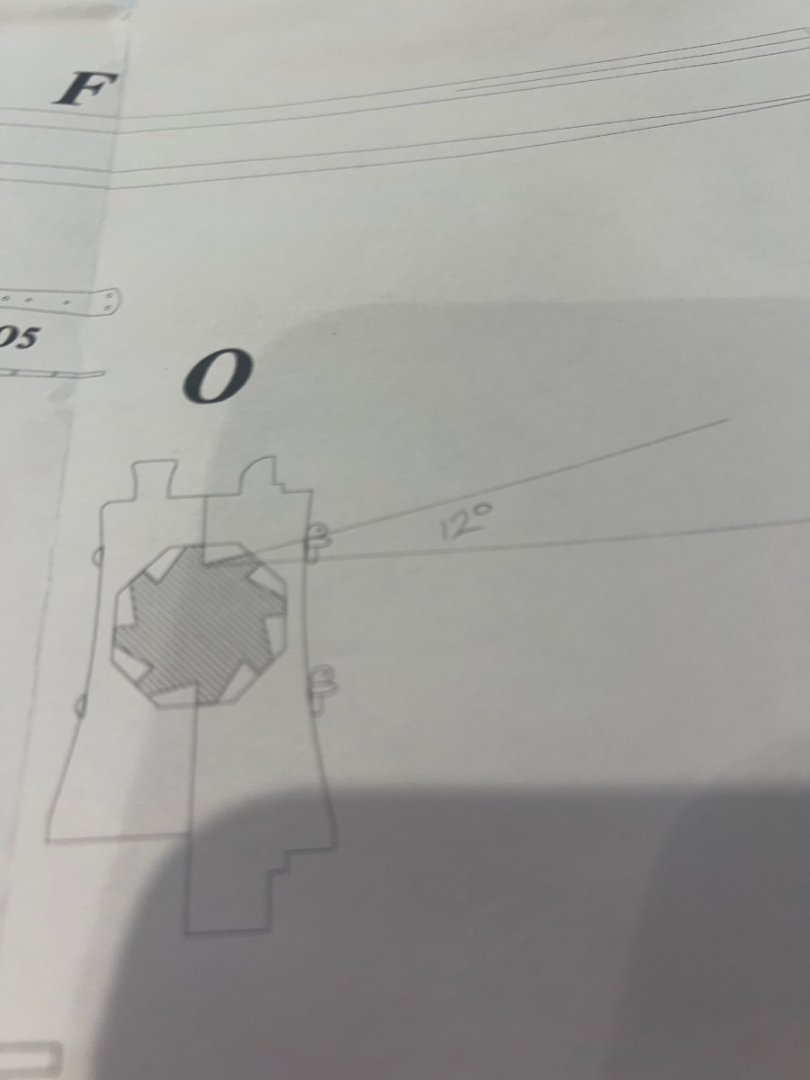
Thank you Vladimir 👍 Hi Dave thanks for your nice comments. I work to the dimensions on Gerards drawings as best I can - so if I measure a piece to be 5.8mm I try and make it that size rather than rounding up to 6mm. I have found that I get very little cumulative error by doing this BTW have a really great holiday you lucky fella 👍 Okay - the windlass 😍 what a lovely piece this is to make on this ship. Although I've not strictly adhered to Gerards drawings as it should be slightly barrel shaped I have enjoyed making this. So first of all I had a bit of play to work out the indexing on my rotary table which you can see standing on the mill slide. Once sorted I shaped a hexagonal piece which was again made by gluing two bits together. Its dimensions are just over 18mm wide it's quite a chuck of wood. Looking at the drawings there is a 3 degree angle to be cut on the length of the windlass and also the pawl cut outs are set 12 degrees back from the hexagonal facets. So I set the 3 degree angle and cut the taper and also rough cut the pawl locations. Once that was done I revised the pawl cuts and milled them to their final size. This is easy to do as long as you do not accidentally reset your mill dials. Then I drilled out the holes for the windlass lever which are set a 90 degrees to each other and go all of the way through too. I also cut the windlass bearings. So now I've ended up with a piece looking like this - Now anyone that does machining knows that my biggest problem is turning the windlass around in the chuck. I cannot grip on the tapered surface with the 4 jaw chuck. So to solve this problem I made some tapered inserts that I glued on using PVA knowing that I can remove them later using IPA. I then turned the windlass around in the chuck and repeated the same processes to the other end. Now the chances of me hitting exactly the same angle with such a Heath Robinson solution was slim. The windlass did not come out entirely symmetrical but it looks ok to me. If I made it again I expect that I would get the same result so upwards and forwards. The next stage was to make the round holes square for the lever which I intend to make later. I'm sorry but I forgot to take any pictures of this process - Its time consuming to get the square hole completely through but the end result is well worth it. Finally there are 2 iron bands that fit around each end of the windlass. These are hard to make and get a correct fit being hexagonal - my advice is just keep at it until you get it right. Due to my taper/angle discrepancy the ends of my windlass differ by 1mm so each one had to be custom made. So here's the final result all cleaned up with blackened iron bands - I've never used brass black before but its very easy to use and the results are lovely. So next I need to make the windlass supports - Thanks everyone for the likes and support with my build Mark


-
That really looks like a great job - as for the later frames being in line and perpendicular I agree with druxey you need a datum on the base of your building board or higher up. This will ensure that the frames are in the correct position. I have found that measuring constantly keeps things just about right. Great build 👍
- 99 replies
-
- 3
-
-
- ancre
- La Mahonesa
- (and 1 more)
-
Hi mate I feel your pain 👍. I ended up making mine twice as getting the transom fillers to fit the fashion pieces is tricky. In the end I glued the transom pieces to the stern post. This kept them still and in alignment which allowed me to file a nice straight angled edge between them and only then did they sit nicely on the fashion pieces. Keep going and you’ll get there 👍👍
- 99 replies
-
- 3
-
-
- ancre
- La Mahonesa
- (and 1 more)
-
Hi Here's one that goes from 4mm - 10mm square https://www.cooksongold.com/Jewellery-Tools/Durston-Square-Plain-Triblet-4-10mm-Hardened-Steel-prcode-999-7227&query=square mandrel&channel=uk Mark
-
In the UK Lidl or Aldi supermarkets sell a Proxxon copy under the label of Parkside. They are a very close copy and about 1/3 of the price.
-
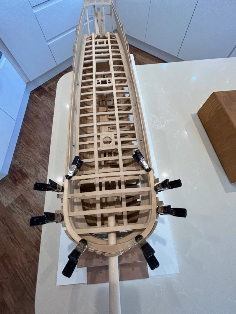
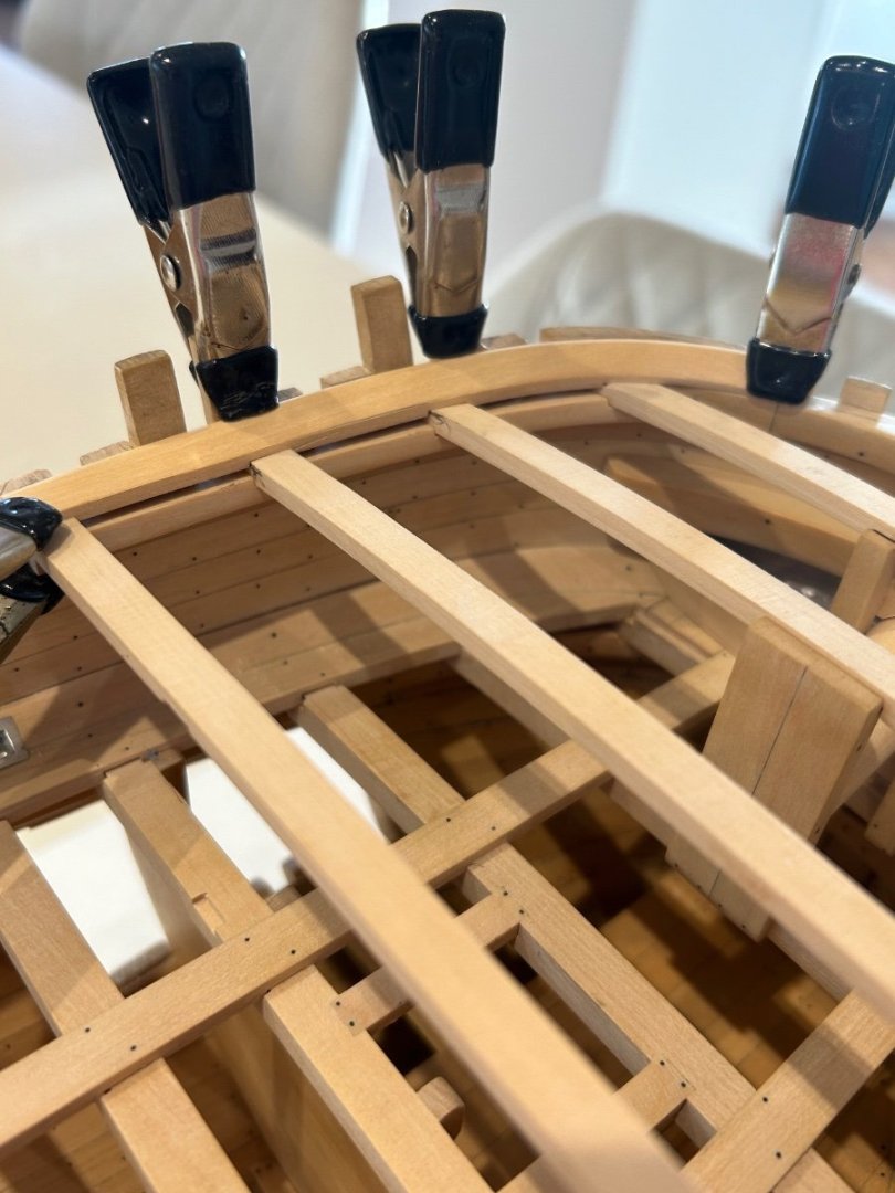
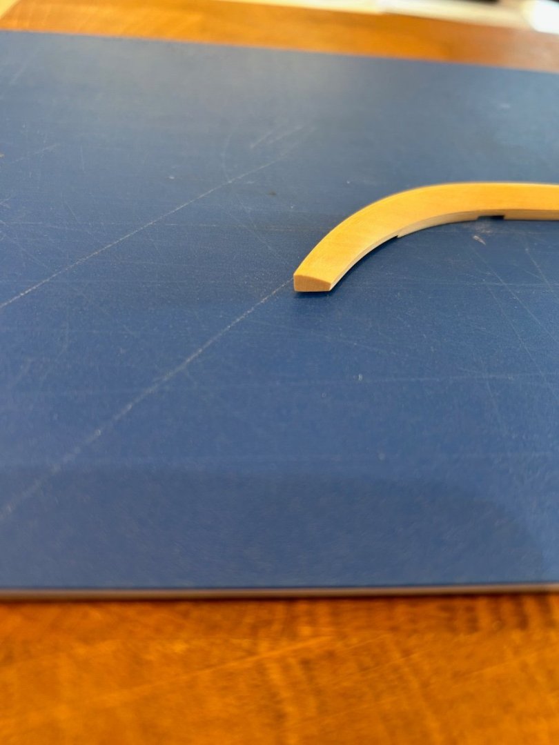
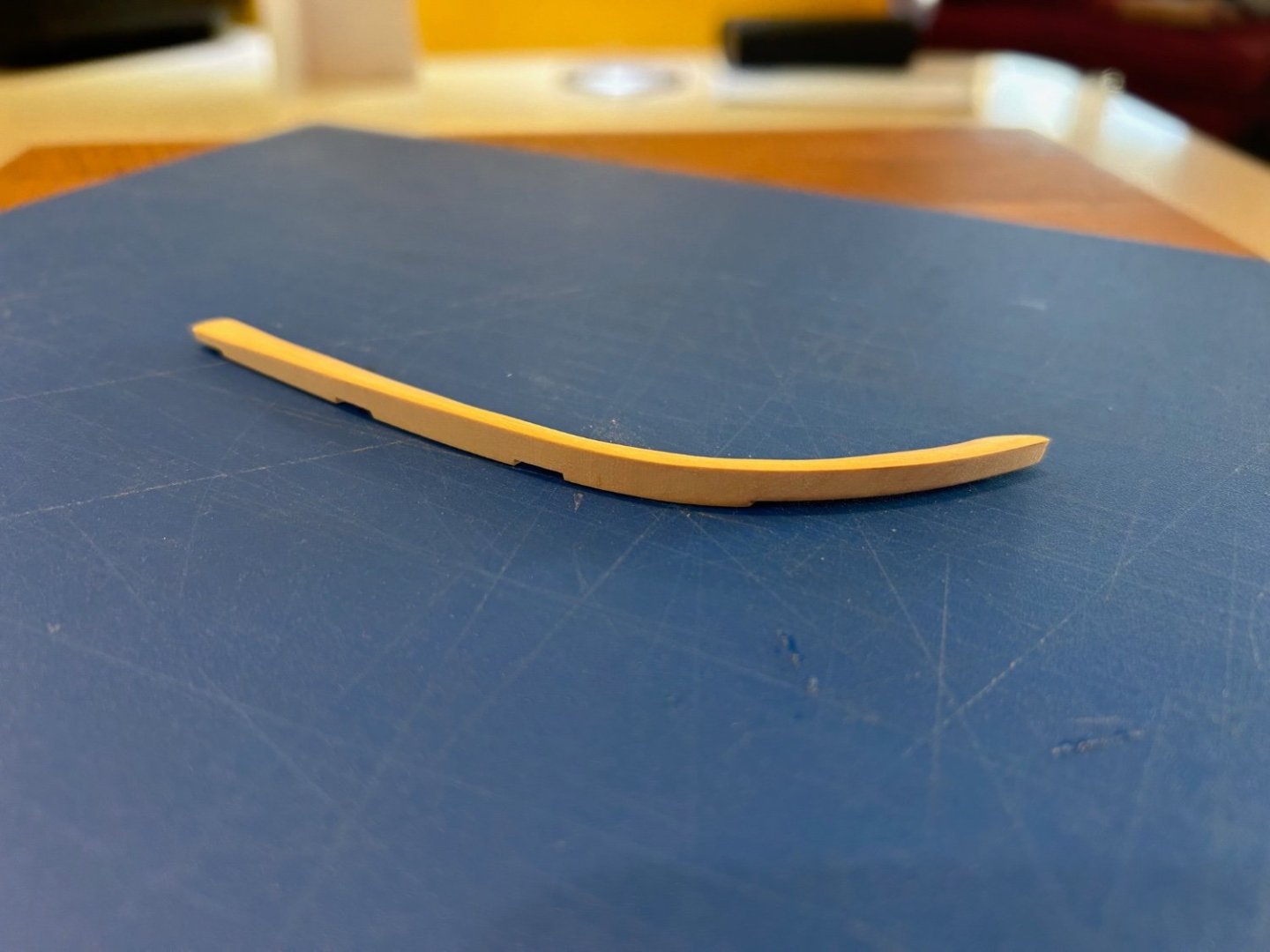
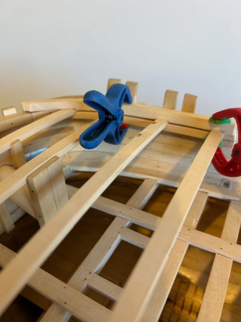
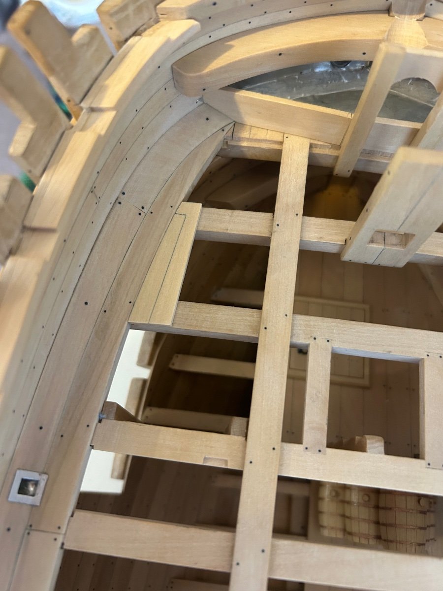
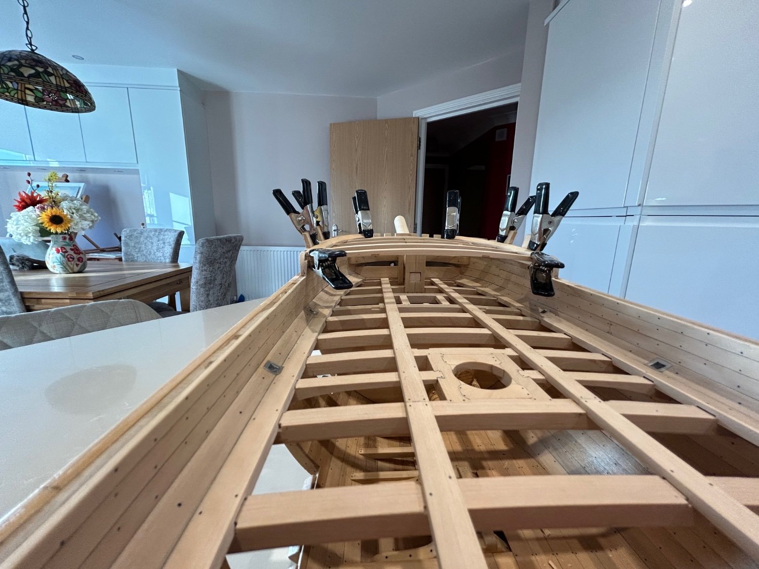
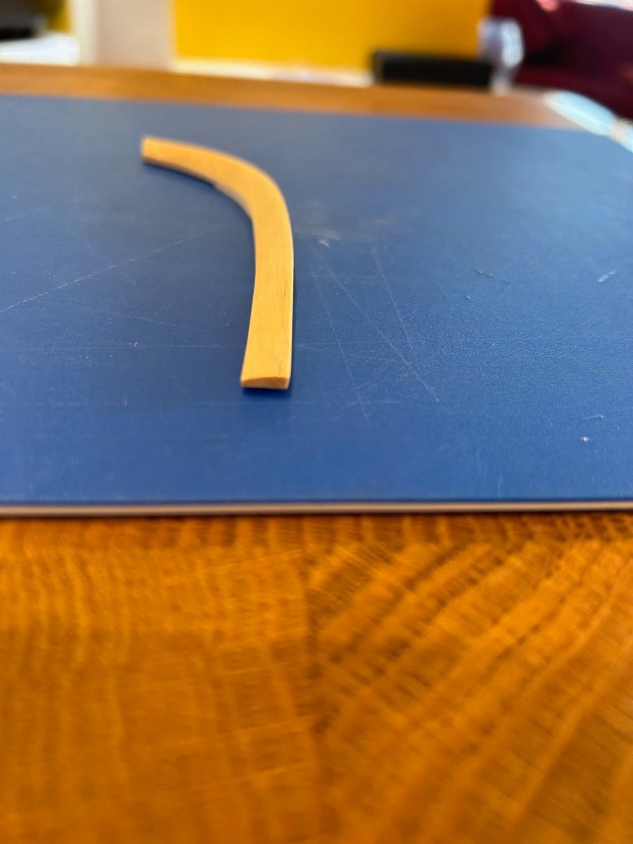
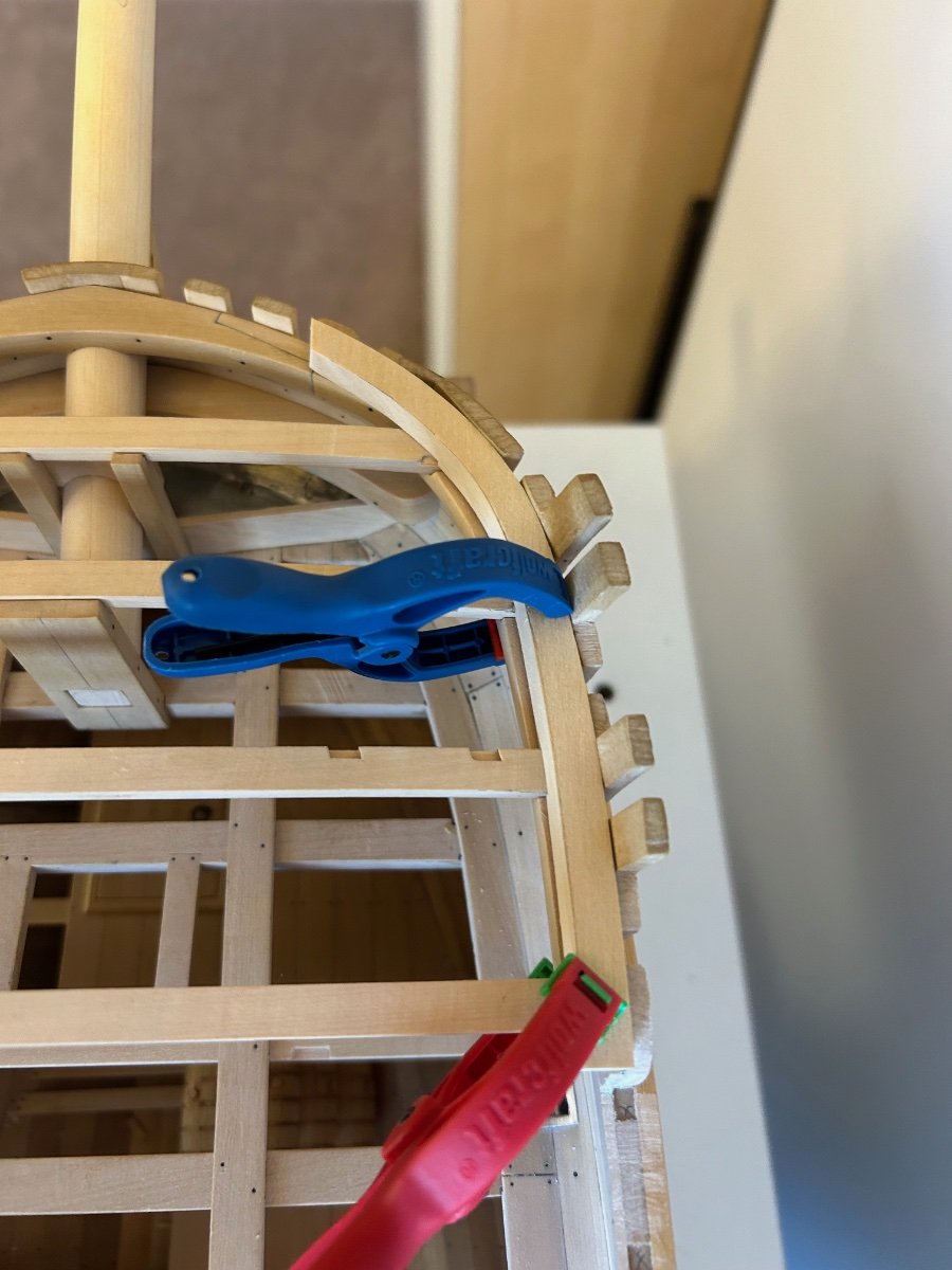
More done this time it's the forecastle deck waterways. As with the main deck these are tricky to make and get a good fit. Here I'm just pretty much roughing out the shape to get a good fit on the hull and beams. I learn't from last time to leave loads of extra material on until the final shaping. This is what the final piece looks like - It varies in thickness, angle and profile. I haven't put any of the making pictures up as its a replica of the process that I followed before. Just dry clamped in place to check that all is ok. It's all still a bit scruffy and needs cleaning up and pencil marks removed but on the whole they fit nicely and now I know that everything lines up. So I can now put these parts away until later as I want to make the windlass, stove and office that sit between these decks. Once they are made and installed I'll finally fit all of these pieces too. Mark