No Idea
-
Posts
1,036 -
Joined
-
Last visited
Content Type
Profiles
Forums
Gallery
Events
Everything posted by No Idea
-
 I echo what Mark has said above but I do mine very slightly differently. I mix very fine sawdust that I make with a Dremel sanding drum into the PVA and use as much sawdust as possible. It kind of turns into a very thick putty that I then push into the gap with a very flexible knife. Its exactly the same thing but it just has a greater content of wood which I would guess at 75% wood - 25% PVA. It does however make it quite hard to sand down as its very tough but the results are pretty good.
 -
I've not seen this kit before but it looks very interesting and I like the way the frames are nice and chunky. That will give you plenty to go at when you do start fairing them. Good luck with your build and I'll be following along too.
-
Hang on I’m English maybe I could end them at the…….oh no maybe not just wishful thinking on my part 😂😂
-
giampeiroricci - thanks mate 👍 Tonphil1960 - building in 1/4 scale is nice but it also means that you have to manipulate 1/4 scale sections of wood. I’ve found this very difficult at times and sometimes think that the smaller scale may have been a better option. It just throws up challenges that I have to find solutions for such as the plank lamination in the post above.
-
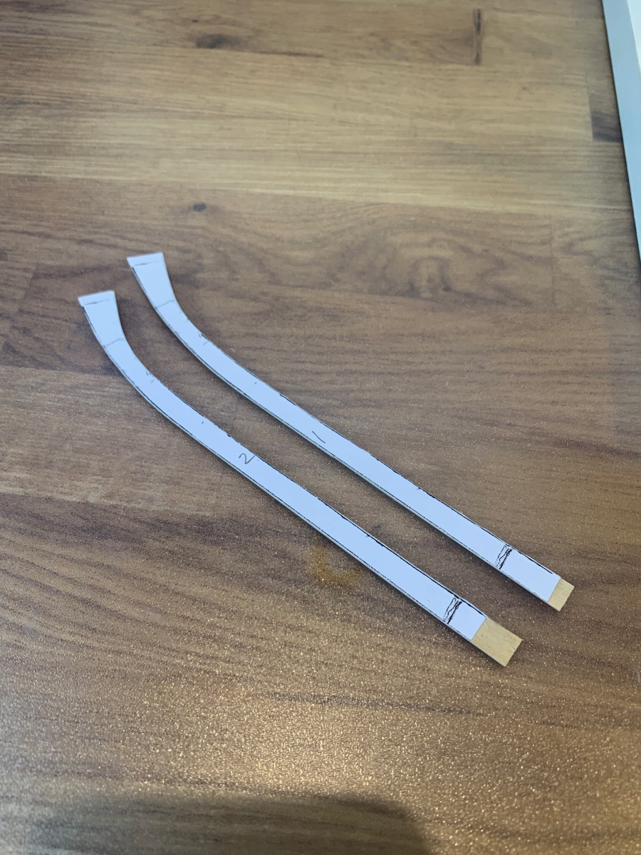
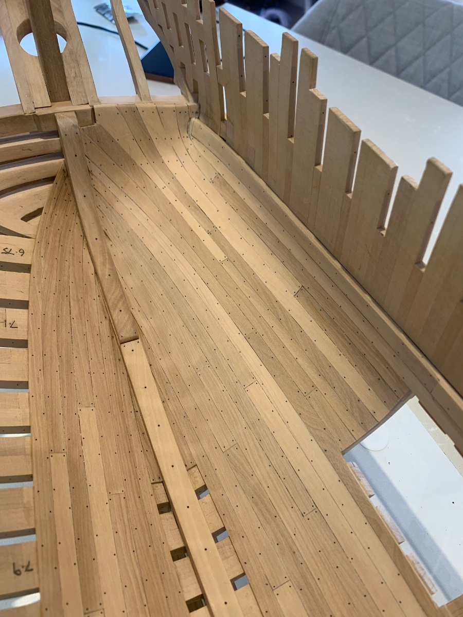
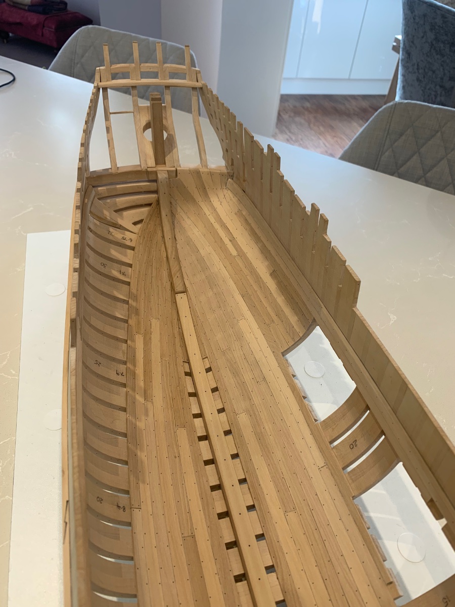
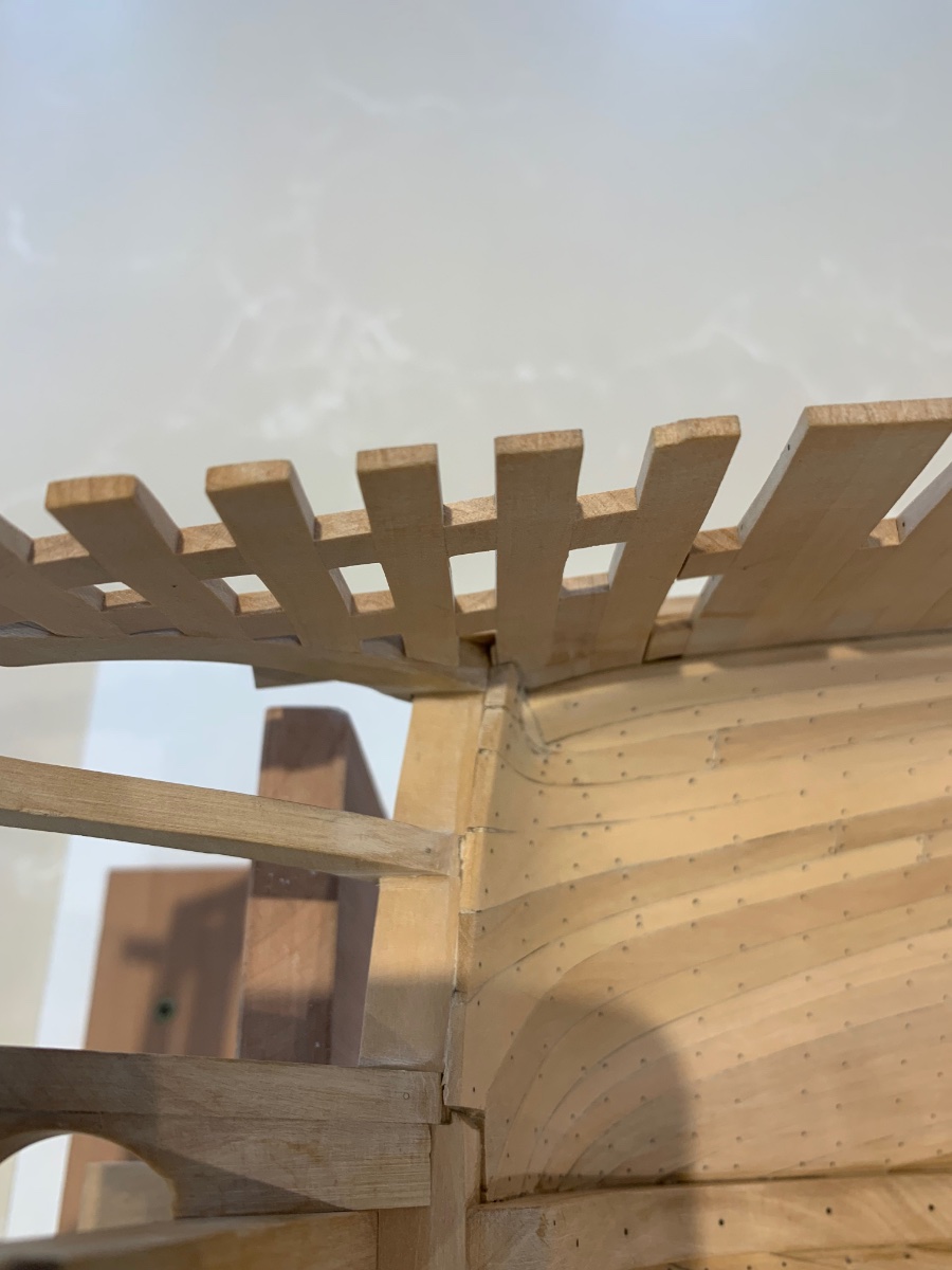
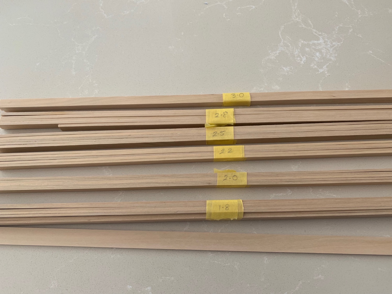
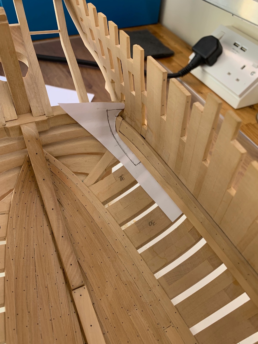
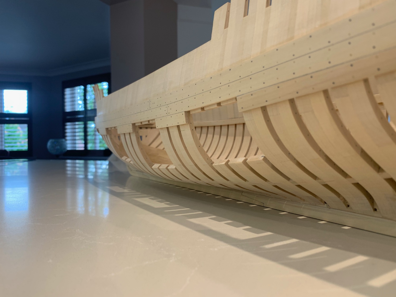
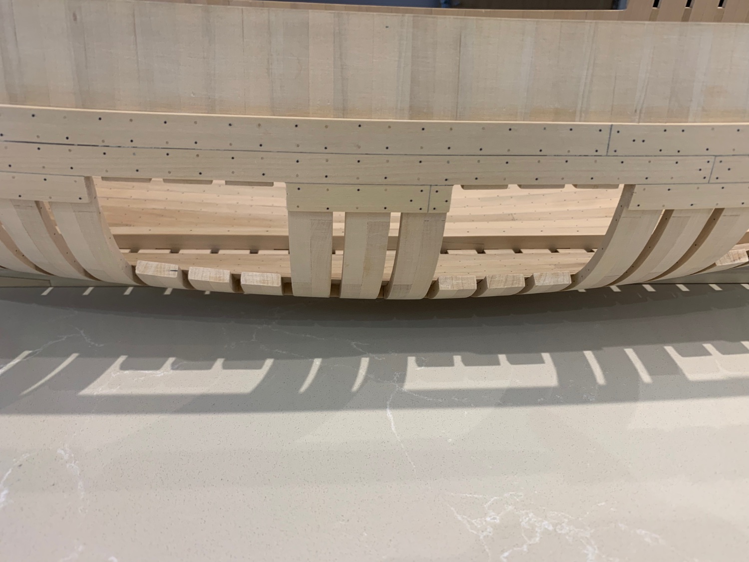
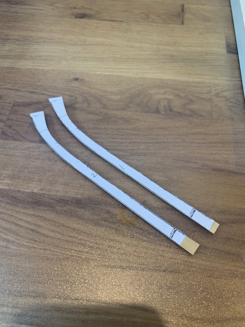
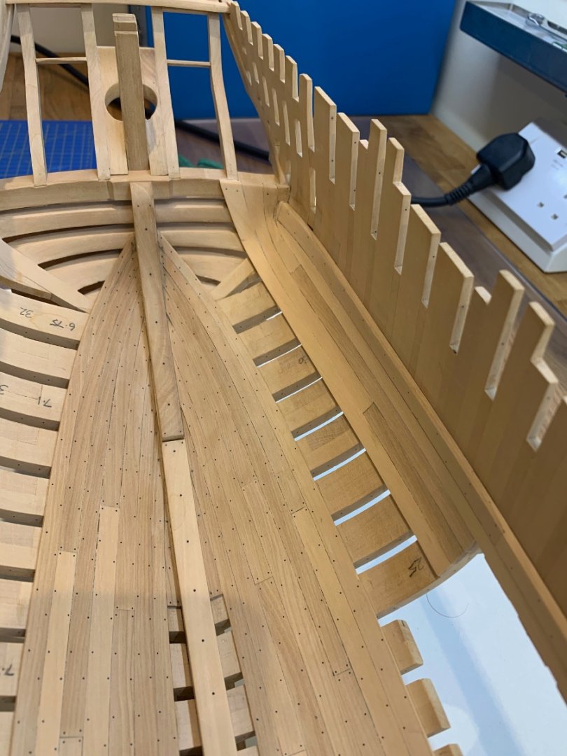
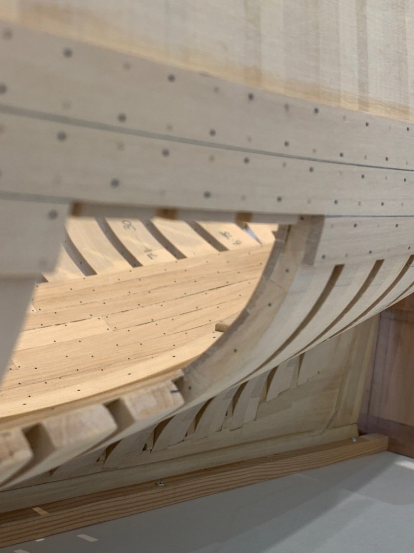
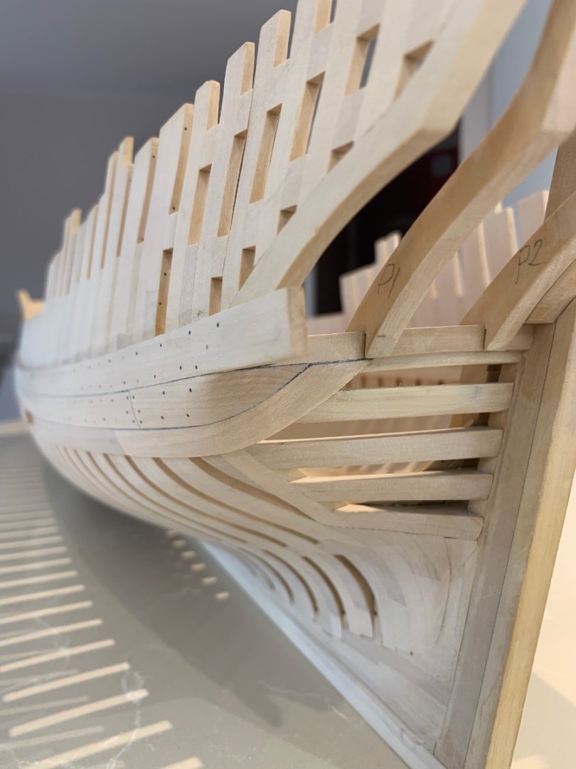
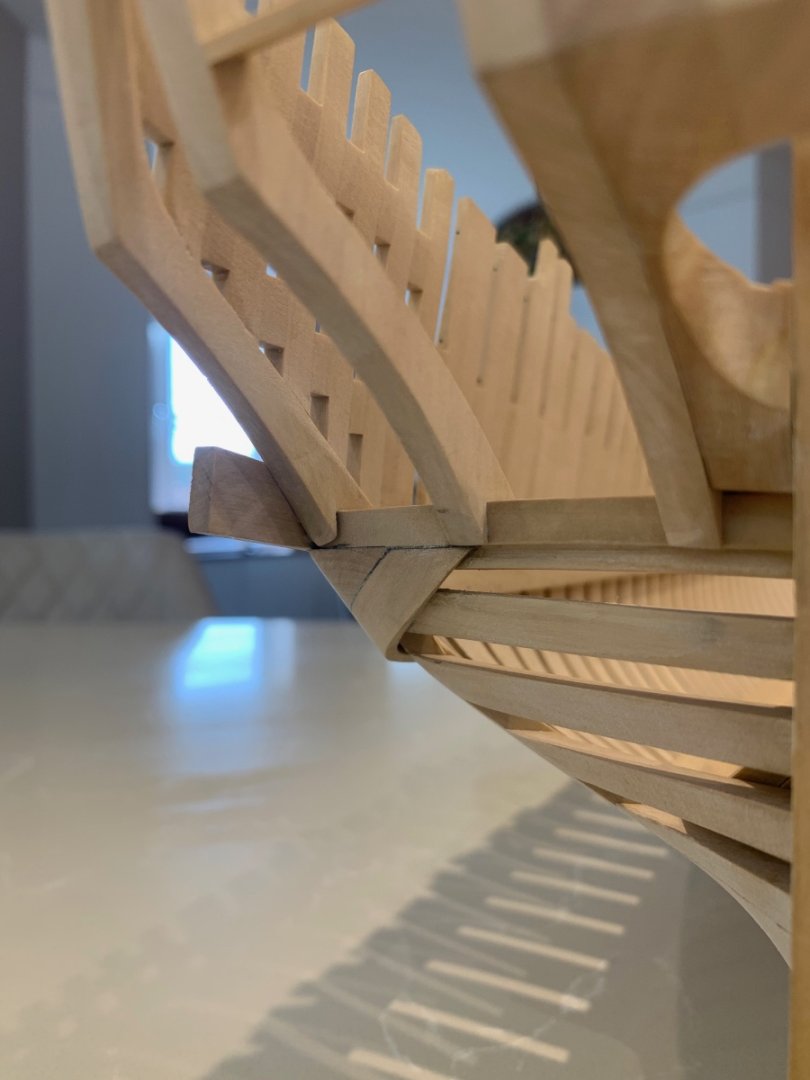
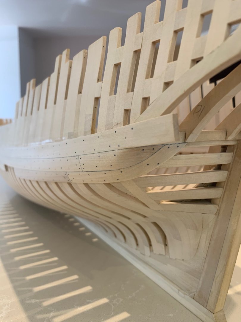
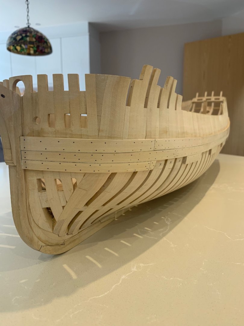
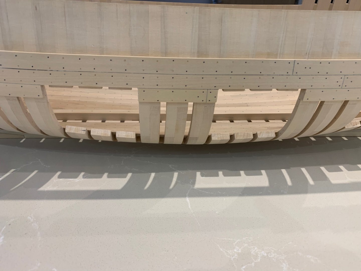
At last I have an update on my build! Thanks for all of the advice given as getting this right has proven to be quite a challenge for me. Firstly I tried carving a plank and it did not go too well and I find that using this method wastes quite a lot of wood. So in the end I used lamination to get around the tightest bends but I also had to spile the planks too. The first 3 strakes underneath the deck clamp had to be made this way before I could revert to solid wood. This plank was made up of 3 layers to get to the correct thickness of 2.8mm The next two planks were made up of 2 layers of lamination the first being 2.5mm thick and the second 2.8mm Now this is my first attempt at ceiling planking and I soon realised that I had made an error earlier in the build. The first lot of planks that I had placed coming away from the keelson had been tapered too much towards the stern. They did not go far enough up the sternson which meant that with my remaining planks I really had to make up some space between them and the new planking on the transom. I had a choice I could either fit a stealer to bridge the gap or exaggerate the flair of the planks on the transom. I decided on the latter and here's the result. Its been a really good learning curve for me and whilst the planking is hardly uniform it is very tight on the frames and transom. Next time I will look at this planking from a completely different angle and get it far more pleasing to the eye. I now need to replicate my mistakes on the starboard side so that it looks symmetrical but I think this will be ok for me to do. Lastly a couple of pictures hopefully showing the planking thickness decreasing from 3mm to 1.8mm as it moves down the frames and across the transom. Cheers Mark


-
The attention to detail is mind-blowing and the production of parts is so precise. Keep the updates coming mate 😎
- 2,623 replies
-
- 5
-

-

-
- heller
- soleil royal
- (and 9 more)
-
I know that others have said it but - wow that is incredible! If the background was removed from the photo I would say it's the real thing.
-
Tilting mount for Proxxon Vise for MF70
No Idea replied to ChrisLBren's topic in Modeling tools and Workshop Equipment
wefalck thats a really nice solution too thanks for sharing mate! -
Tilting mount for Proxxon Vise for MF70
No Idea replied to ChrisLBren's topic in Modeling tools and Workshop Equipment
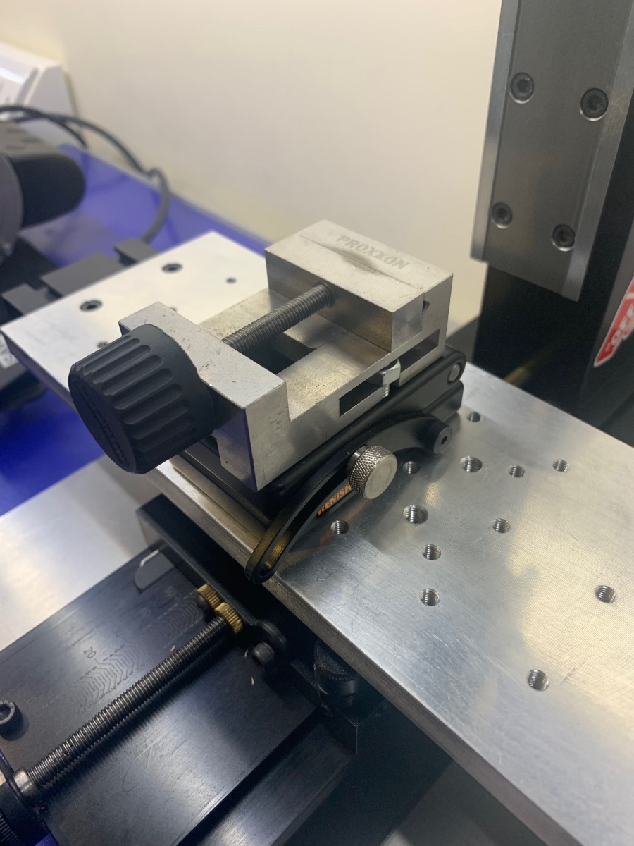
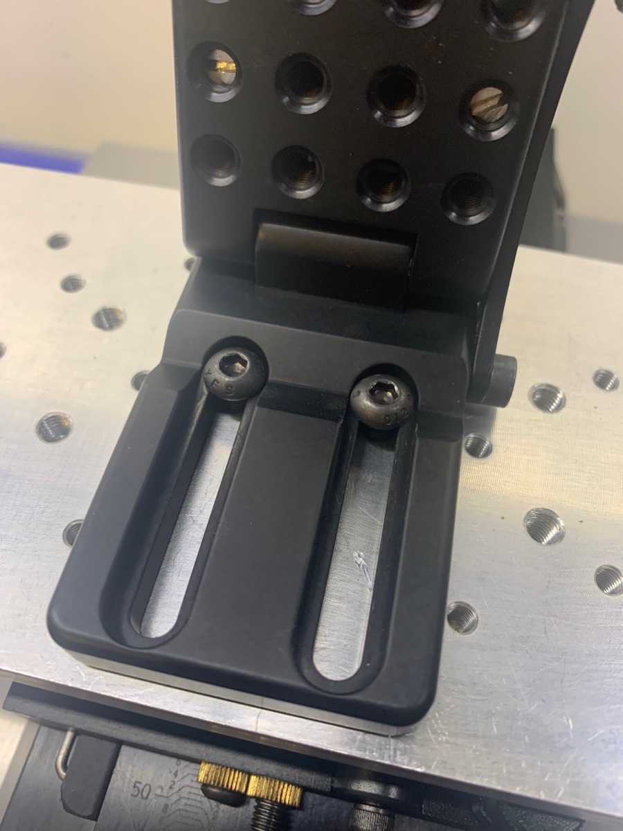
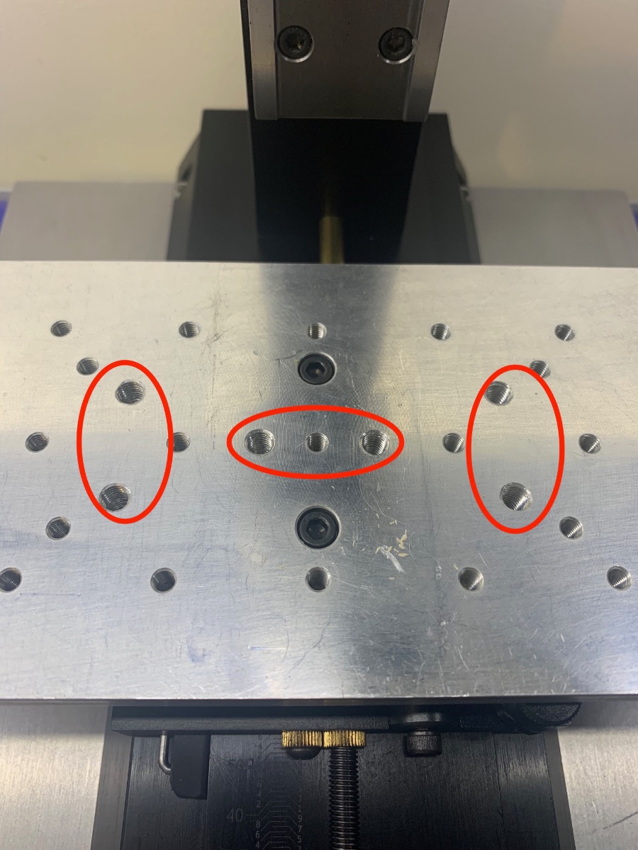
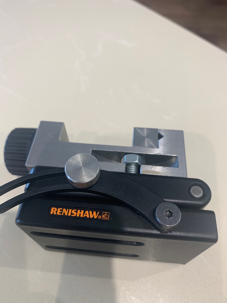
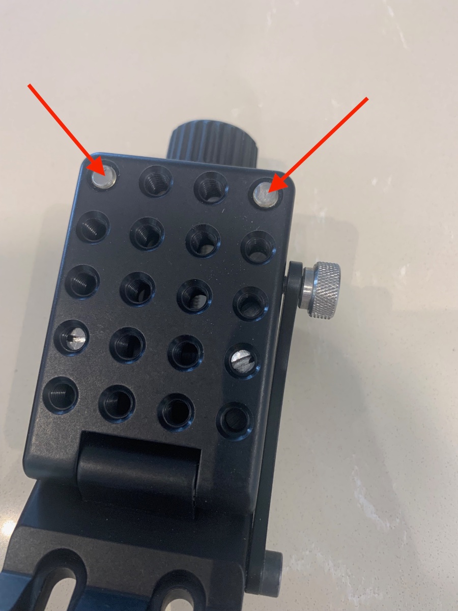
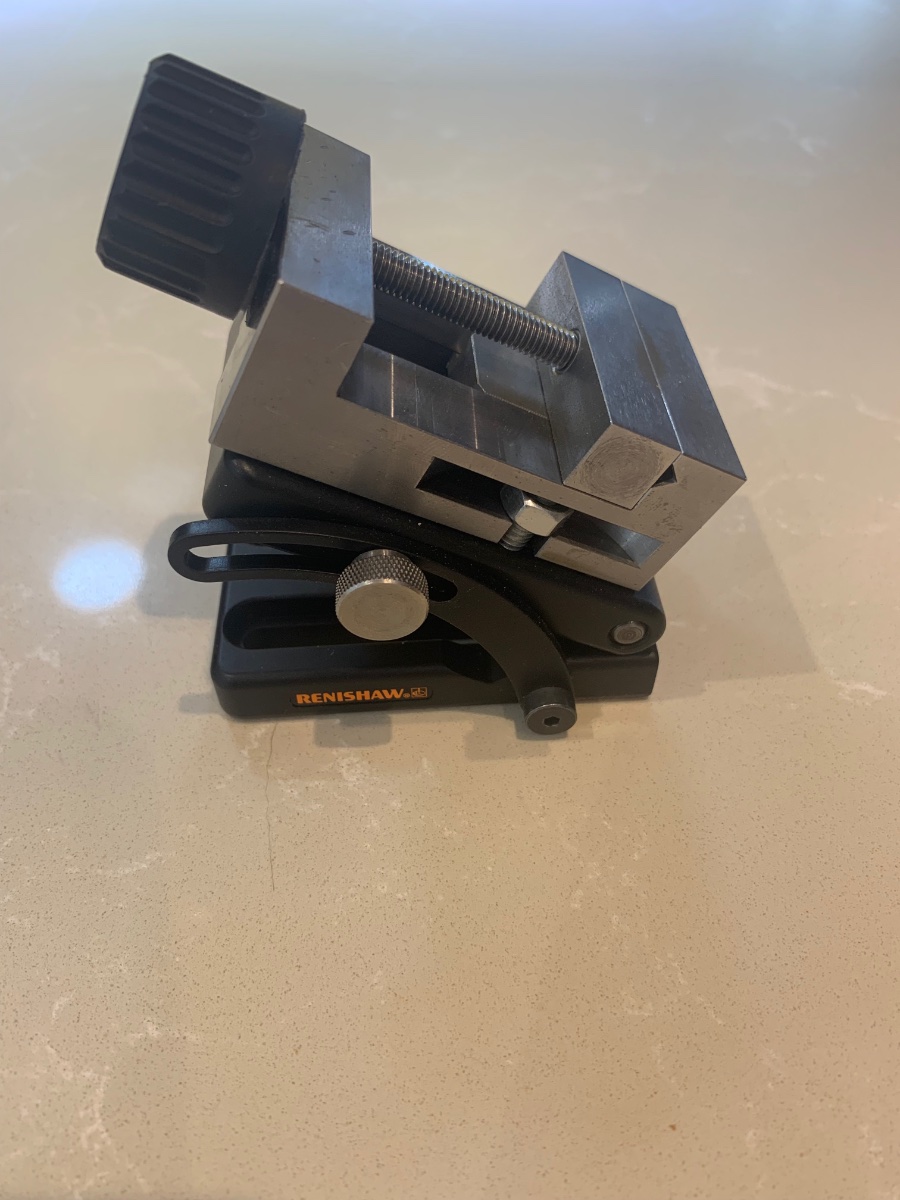
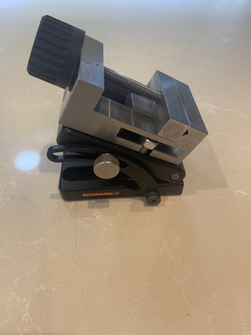
Hi I'll chime in here as I've got one and can probably help. This is what the part looks like when attached to a Proxxon vice - its very small and this is the 6mm version of the tool. This part is designed for the scientific industry for checking accuracy etc. It's strong enough to hold wood securely but I have no experience of machining metal using this part. My thoughts are though that I probably wouldn't do this - I'll just stick to wood. When its closed shut the two mating surfaces are not quite parallel and I solved this by placing 2 - 6mm studs in the holes shown and then adjusted them until the 2 faces were exactly parallel. They are simply held in place with a medium thread locker. This means that I don't have to worry about any adjustment once closed and I haven't taken the vice off of the angle plate since fitting. The 2 lower studs with the slots in secure the vice to the plate. Here's mine attached to the tooling plate on my Sherline mill Its held down by 2 - 6mm bolts that are supplied with the vice. I drilled some extra holes into the tooling plate and tapped them out. These really make switching the vice around very easy. This can easily be fitted to a Proxxon MF70 mill but remember that you already have less head high between the table and cutter so you will loose another 25.50mm between these 2 points. This is not an issue on the Sherline as it has a much taller head height. Renishaw do not keep these parts in stock so if you do order one you will probably have to wait a few weeks for delivery. Its worth giving them a call to see what they can do. I hope this helps - Mark


-
Thanks all - The issue I'm having is getting the plank bent without it cracking or snapping. I've made this plank several times out of a wider piece of wood and thats not been my issue. All of the above advice is absolutely spot on - I've even tried soaking a piece for an entire week but the bend is so tight at this point it cracked on the bend as well. The plank at this point is 2.8mm thick so its a fair piece of wood to bend and I've made sure that at the bending point the grain is running correctly towards the transom. I guess this is why I've reached the conclusion that this particular plank needs to be carved to shape. I'll keep at it until I get a working solution
-
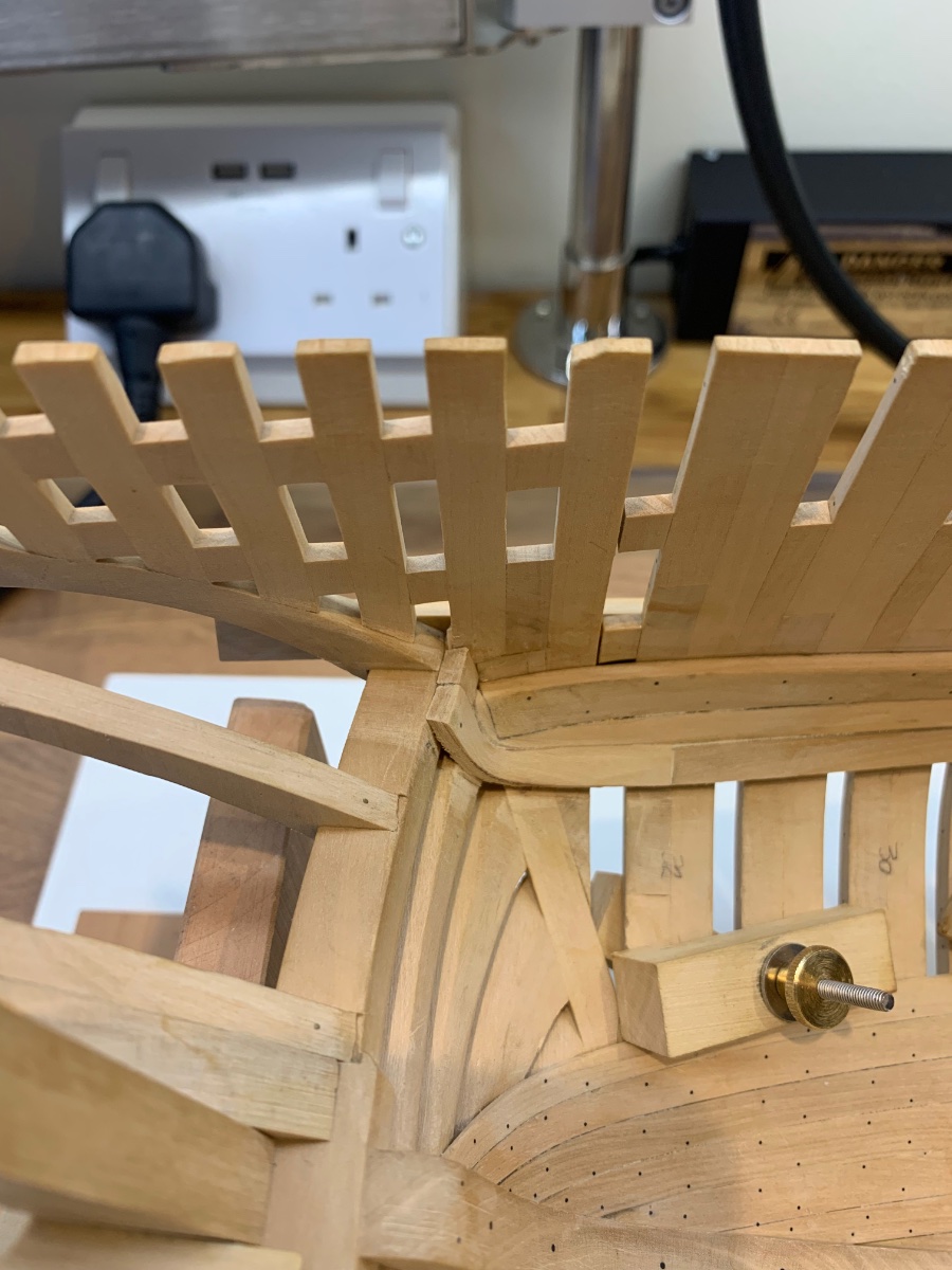
Hi All Well I'm well and truly stuck on this build at the moment. I think all builders have a particular part of a build that they find difficult and mine is definitely the ceiling planking. I'm trying to make the transition from the side planking to the planks that run up the transom. The bend is so tight I'm finding it difficult to find a solution. So far I've tried soaking planks and then loads of heat but no matter what the plank ended up splitting. I've tried spiling before soaking the plank to reduce the amount of bending and again the plank ended up splitting. I think I've spent a good couple of weeks on this now and I'm no further forward with a solution. Its only this corner that causing the problem and I can see that once solved the rest will follow quite easily. I could bodge it up but I'm not going too - so how to solve this problem??? I believe now that this particular plank requires carving just like the one on the outside of the transom. I'm going to give it a go but the shape is going to be very hard to replicate. Funnily enough my wife has suggested modelling clay to see the shape in 3D and you know what I think she may be right. So why my post - for first time scratch builders like me - don't give up! Carry on and find a solution even when you think its got you beat!! I don't have a solution yet but I will at some point. On the positive side all of the planks are cut at the correct thickness Also my template making is so much better too And my desire to get completed is under control - well sort of 😜 Anyway I'm still at it and I will get this sorted. Thanks for being part of my learning Cheers Mark


-
This is not my sale and I have nothing to do with the sale either. However I don’t see these very often but here’s one for sale if any of the UK builders want one. I just happened upon it. https://www.ebay.co.uk/itm/295237997664?mkcid=16&mkevt=1&mkrid=711-127632-2357-0&ssspo=k809bnrjt7-&sssrc=2349624&ssuid=ygWIHLd-RE2&var=&widget_ver=artemis&media=COPY Mods I don’t know if this is in the correct place or even allowed. I’ll leave it with you to decide. Cheers Mark
-
Ultimation Model Slicer Anyone?
No Idea replied to Bill Jackson's topic in Modeling tools and Workshop Equipment
It looks like a nice tool - however this falls into the "Not really needed modelling tools" category for me. There are so many expensive modelling tools that just don't make the grade. As has been said there are so many ways to make this type of cut and basically its a levered razor blade. It costs $175 ........wow..........add $300 and you can buy a Byrnes table saw. Its 3 times the price and 100 times the tool. -
Hi Gary - you are spot on there mate my mistake. I guess I was just showing the attachment but gave no thought about what was actually on offer!! The 90 degree attachment that Foredom sell is as you have shown and yes you do need a H30 hand piece to attach it too.
-
It is possible to buy 90 degree hand pieces that fit straight onto a Foredom motor..............I'll let you see the price!! I wouldn't pay this and I don't mind paying for top tools but this is well over the top in my opinion. https://moleroda.com/product/foredom-handpieces/?attribute_handpiece-type=35RAA+Right+Angle+Handpiece+3mm+Collet&gclid=EAIaIQobChMIwaHHrYSh-gIVZoBQBh2jeQ2fEAQYASABEgLJPfD_BwE However Foredom do make an attachment that fits onto the H30 hand piece but its quite bulky https://www.foredom.net/product/a-69224-right-angle-attachment/
-
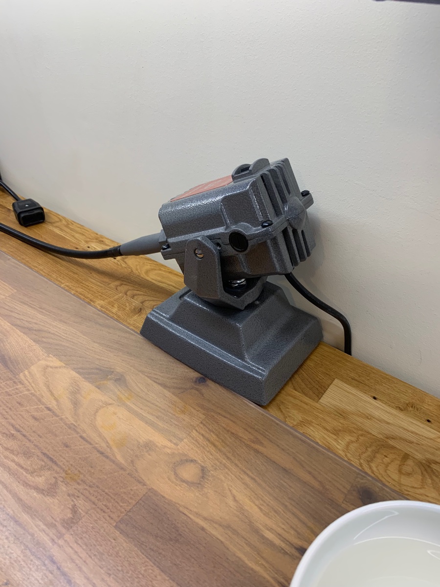
Great advice there from Jaager but I'll add a little if I may. The TX which is a fantastic motor is only available in 115V so it cannot be used in the UK without a transformer. The SR may seem the cheaper option but for ship building I have never been able to stall the motor on mine as the torque is over and above what I need. I have also found that I do not need to awl to make starter holes. The reason being is because I can put the drill bit where it needs to be and start the drill at such low RPM using the foot pedal that the bit just does not drift. This is the best thing about the foot pedal - the starting RPM is governed by the user and not the tool. As for the router made by Stewmac - goodness me how nice does that tool look!!! I've had this on my radar for quite some time but it will have to wait.
-
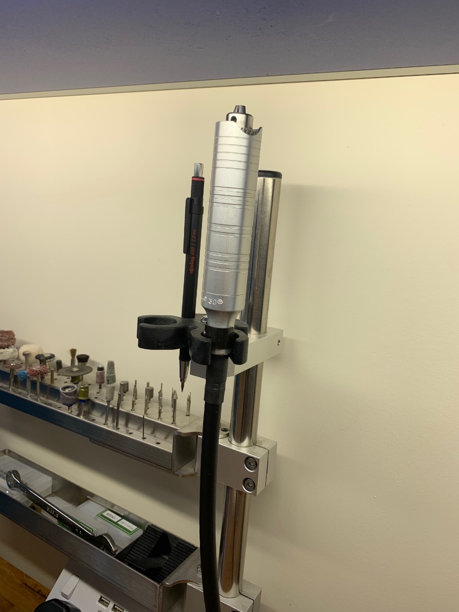
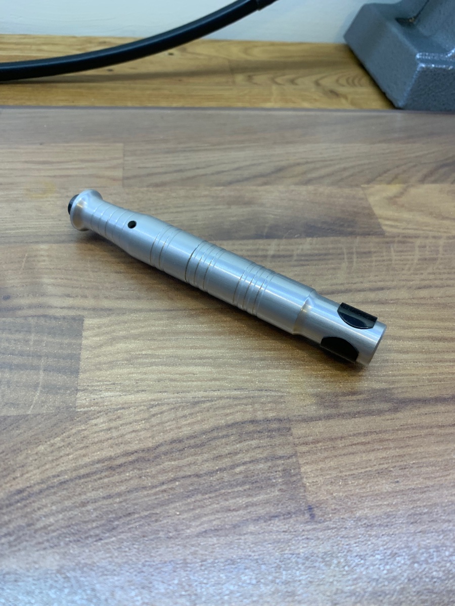
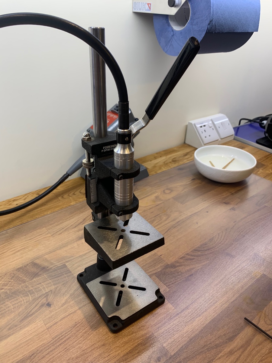
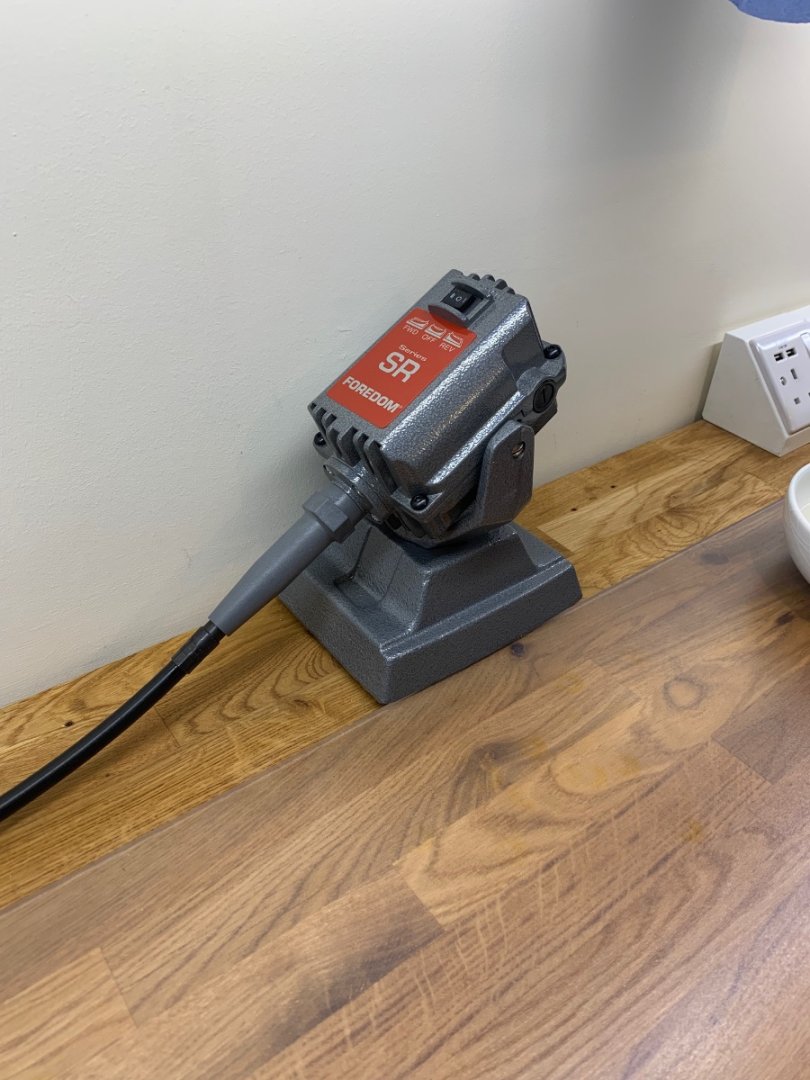
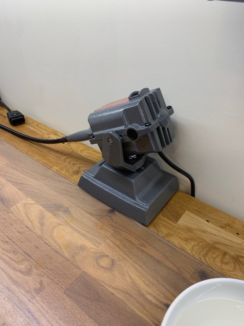
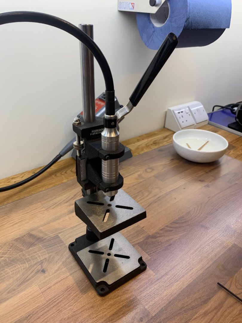
Hi Kevin I've been using a Foredom tool for quite a while now and its not comparable to any high speed drill. The torque and slow speeds just give you the accuracy and control that you want. So what have learn't from my ownership? Firstly I no longer hang my Foredom motor up like jewellers do. It's far too restricting and I've swapped to a desk mounted base as I can literally put this anywhere that I want. I have found this to be a much better solution and I would recommend the SR motor with a foot pedal control with a key drive shaft. Next the main hand piece is a H30 which takes drills up to 4.0mm and will just about do 95% of all of your tasks. Foredom also make a beautiful drill press that the H30 slides straight into and does a fantastic job. I also have another hand piece which is the H28. Its about half of the diameter of the H30 and its much smaller to hold in your hand. Foredom make some really nice micro chucks that fit nicely into the supplied collet with this hand piece. I hope this has been some help - Oh also buy from a registered Foredom dealer as there are so many rip offs out there that are not as good as the real thing Cheers Mark


-
I find your work so inspiring mate. That light is on another level it must have taken you hours to complete but what a beautiful result.
-
Incredible work on the gratings - the more you look at them the more the small details are revealed.
-
That’s wonderful work 👍👍
-
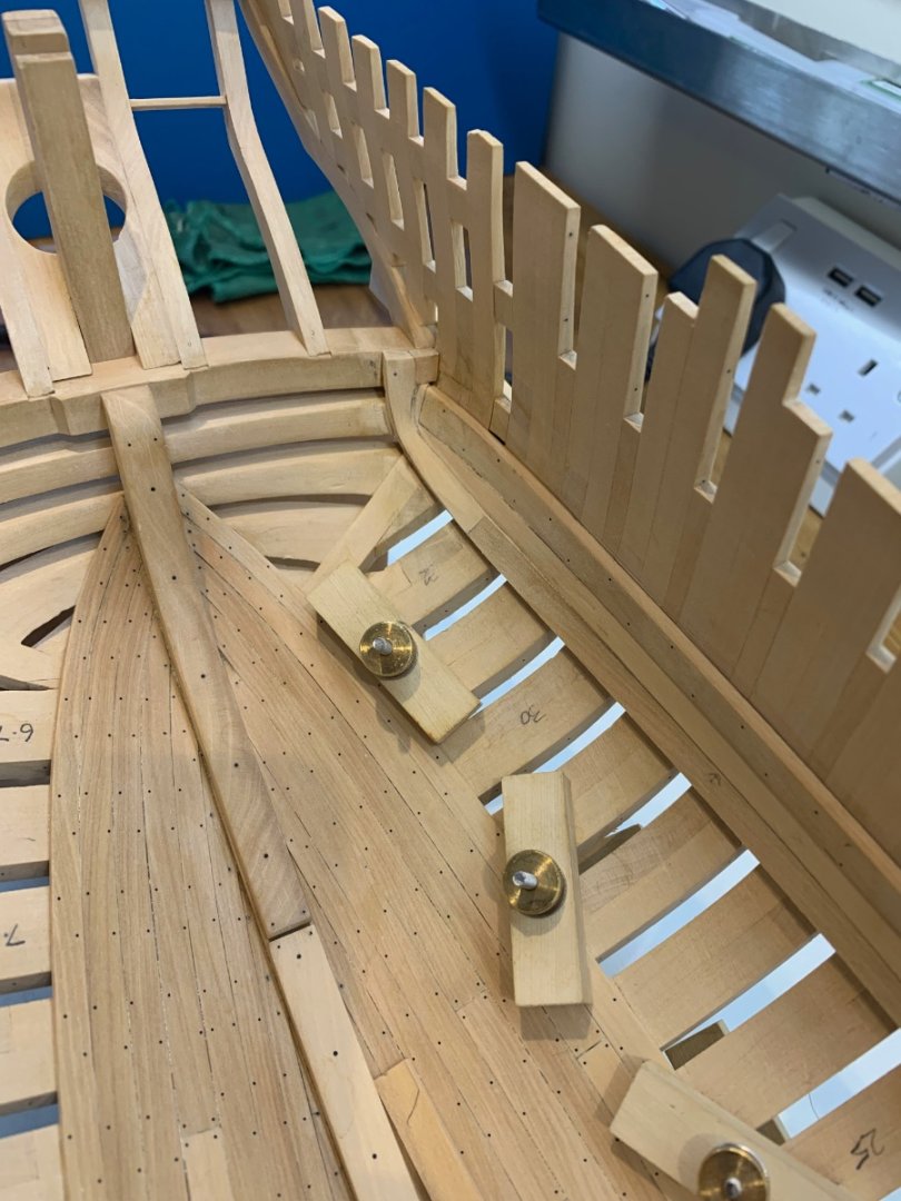
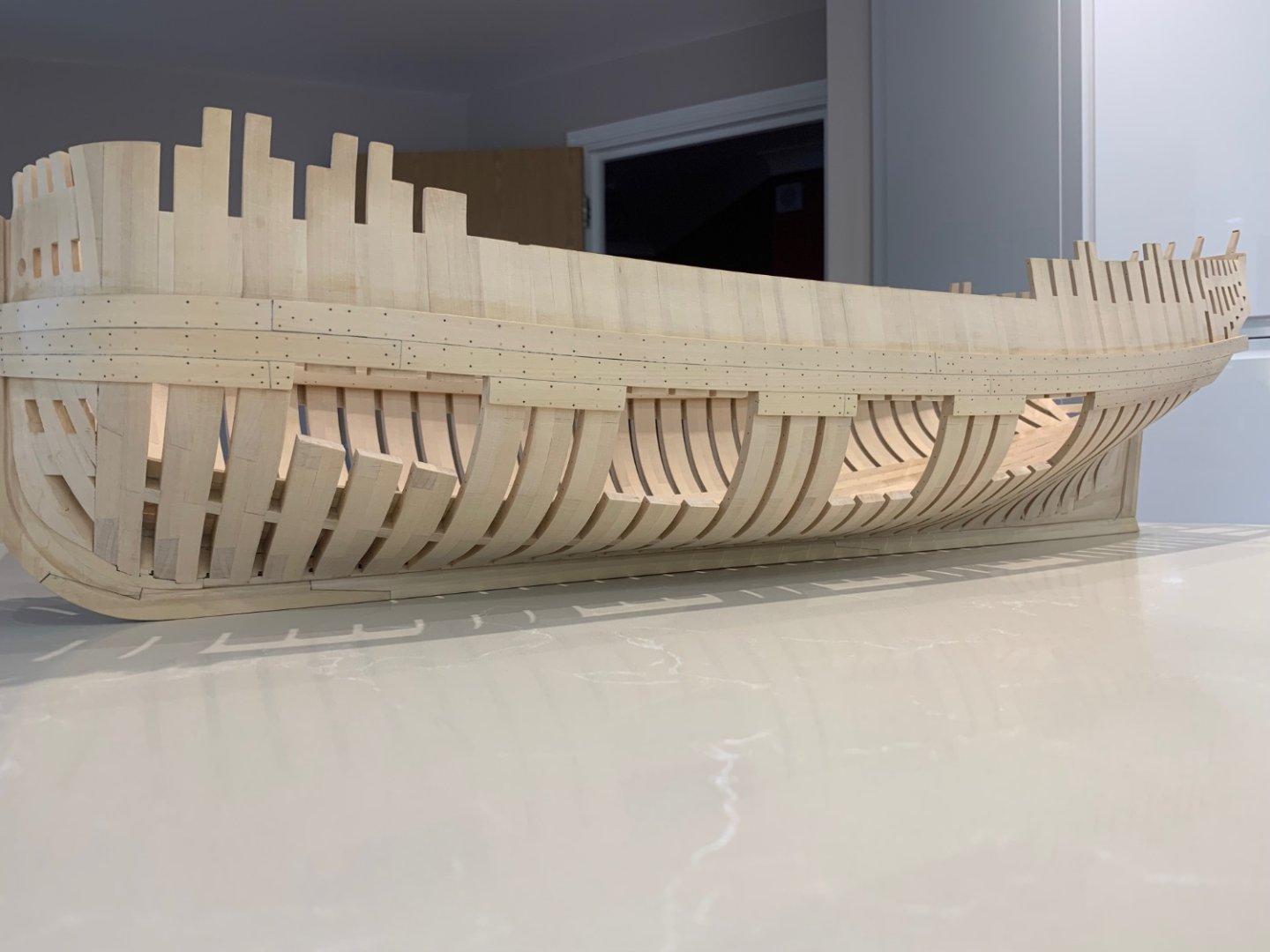
Hi all - Some more done on Le Rochefort and thanks for all of the nice comments and likes. I fitted the next plank down on the port side to frame the cut outs. It was a bit tricky getting it around the stern as this plank is still 3mm x 10mm and its a very tight bend. It also has to fit into the rabbet but I'm really pleased the way its turned out. The bow was a lot easier to fit and I also placed the iron and wood nails as before Next I marked out the cut outs on the port side - Don't laugh but I've been putting cutting them out for nearly two weeks as I just couldn't do it!! Anyway I've done it now so no going back. The reason for the small opening at the bow is because there is a small deck on the inside and the beams need somewhere to sit on the frames. So the next job is to finish the ceiling which is going to take me a while as I need to plan it out first. As soon as I have something to post I'll get it on here. Cheers Mark

-
Wow your work is exceptional!!! I'll be following your build too.
-
Just my thoughts on this and I'm new to building frames too................. Firstly accuracy is the most important thing as cumulative errors make such an impact over the entire hull. So as suggested you need some digital callipers to make your measurements exact. Secondly use a hardwood such as Costello or Pear wood as it's easier to be accurate as it holds an edge. I didn't really understand this until I used it. Thirdly the bevels that are marked on the drawings show the exact final shape and it's easy to just shape the frames to these lines......however the chances of anyone lining up 50+ frames to the exact alignment are slim. So use them as a guide and leave some on for final shaping. Forth - I use permagrit tools for rough shaping too and have found them to be excellent for this job. But they do leave deep score so again leave something to work with to make your frames look pretty. Now that I've had a go I prefer using spoke shaves. Finally - building a Pegasus as a first plank on frame build. That is one hell of an ask as it's going to be an epic build which will take years. I've started much smaller and I'm happy with the challenges my little POF build is throwing at me. Good luck and please keep us updated as I'm in on your build 😀
-
Jim Byrnes Thickness Sander Operation Tips
No Idea replied to ChrisLBren's topic in Modeling tools and Workshop Equipment
Just seen this thread and I used to have the same problem when I first got my thickness sander. A few years later and I now know that it was just the way I was using it and not being familiar with its use. So here's what I do - As soon as the wood being fed through pops out on the machined side I put my thumb on it to keep it tight to the feed table. The reason I used to get dips was because I allowed the wood to raise slightly off of the bed. I feed through by hand using a constant pressure on the sanding drum and let the drum do the work. I only use a feed through stick at the very last moment - I also use the widest stick that I have to keep the piece square to the sanding drum. Also a 24" piece creates a lot of weight at the end of the sanding run as so much of it is unsupported once machined. Just use loads of thumb pressure to keep it all flat and you will get the piece that you need. Also as wood tends to cup - swap the plank around end to end and and turn it over often. I have found that this method gives me the precise results that I want time after time. I have removed 3mm in thickness with no issues at all except for the painful loss of so much great wood to saw dust!!!