.jpg.f26acc9a74319261612561bfa7da1303.jpg)
vaddoc
-
Posts
1,600 -
Joined
-
Last visited
Content Type
Profiles
Forums
Gallery
Events
Everything posted by vaddoc
-
.thumb.jpg.6fd4c1b78768bb3efd745ab810936005.jpg) My condolences Brian. I hope things get better with time. You are doing a fantastic work, I am sorry I do not have the time to visit as often as I would like to. Now, I had not realised that the armour plating was actually railroad tracks. The weight must have been very considerable and it is impressive that it is all secured essentially on a wooden frame. I also find very interesting that despite all the armour and guns those boats were still ramming each other. Your paddle wheel is truly very impressive, well actually the whole model is wonderful. The red oxide paint is very nice. Regards Vaddoc
My condolences Brian. I hope things get better with time. You are doing a fantastic work, I am sorry I do not have the time to visit as often as I would like to. Now, I had not realised that the armour plating was actually railroad tracks. The weight must have been very considerable and it is impressive that it is all secured essentially on a wooden frame. I also find very interesting that despite all the armour and guns those boats were still ramming each other. Your paddle wheel is truly very impressive, well actually the whole model is wonderful. The red oxide paint is very nice. Regards Vaddoc -
Great progress GL, you ve done a ton of work! This is a very nice and different approach, your choice of wood is also interesting. I ve never used ebony but I have used mahogany. Beautiful but difficult wood to work with and after a few (10) years of exposure to light, the colour has changed from red to brown. I am really very interested to see how your planking will come out and what challenges may appear, also how much spilling your hull will need. How long is the hull and how thick your planks? Regards Vaddoc
- 153 replies
-
- 2
-

-
- Ancre
- Bruno Orsel
- (and 2 more)
-
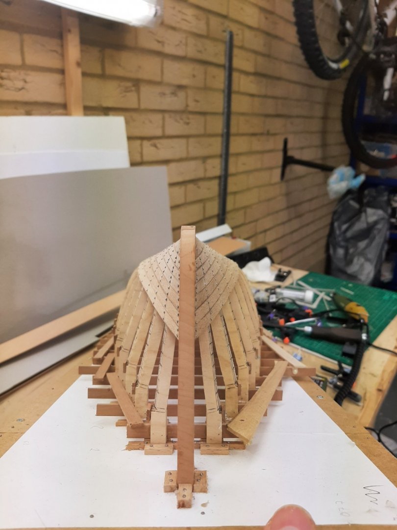
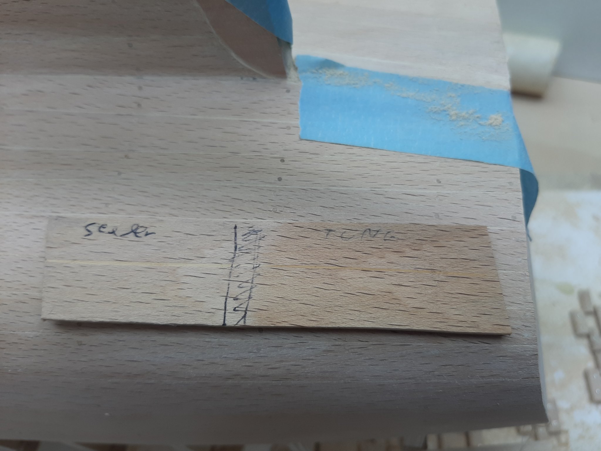
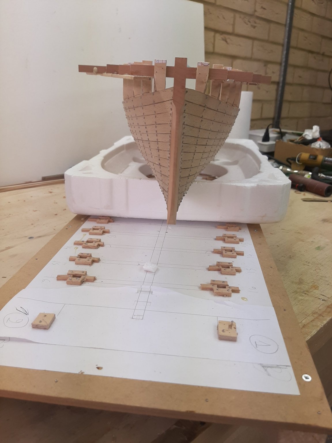
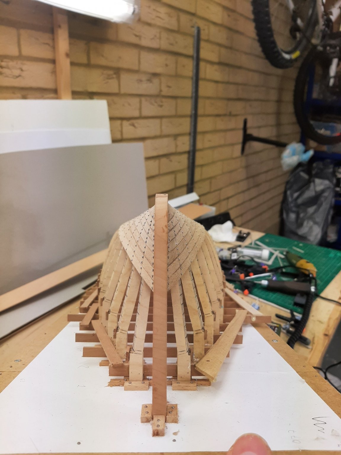
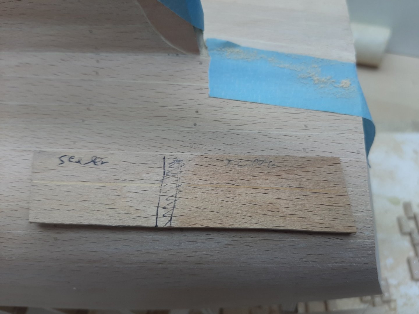
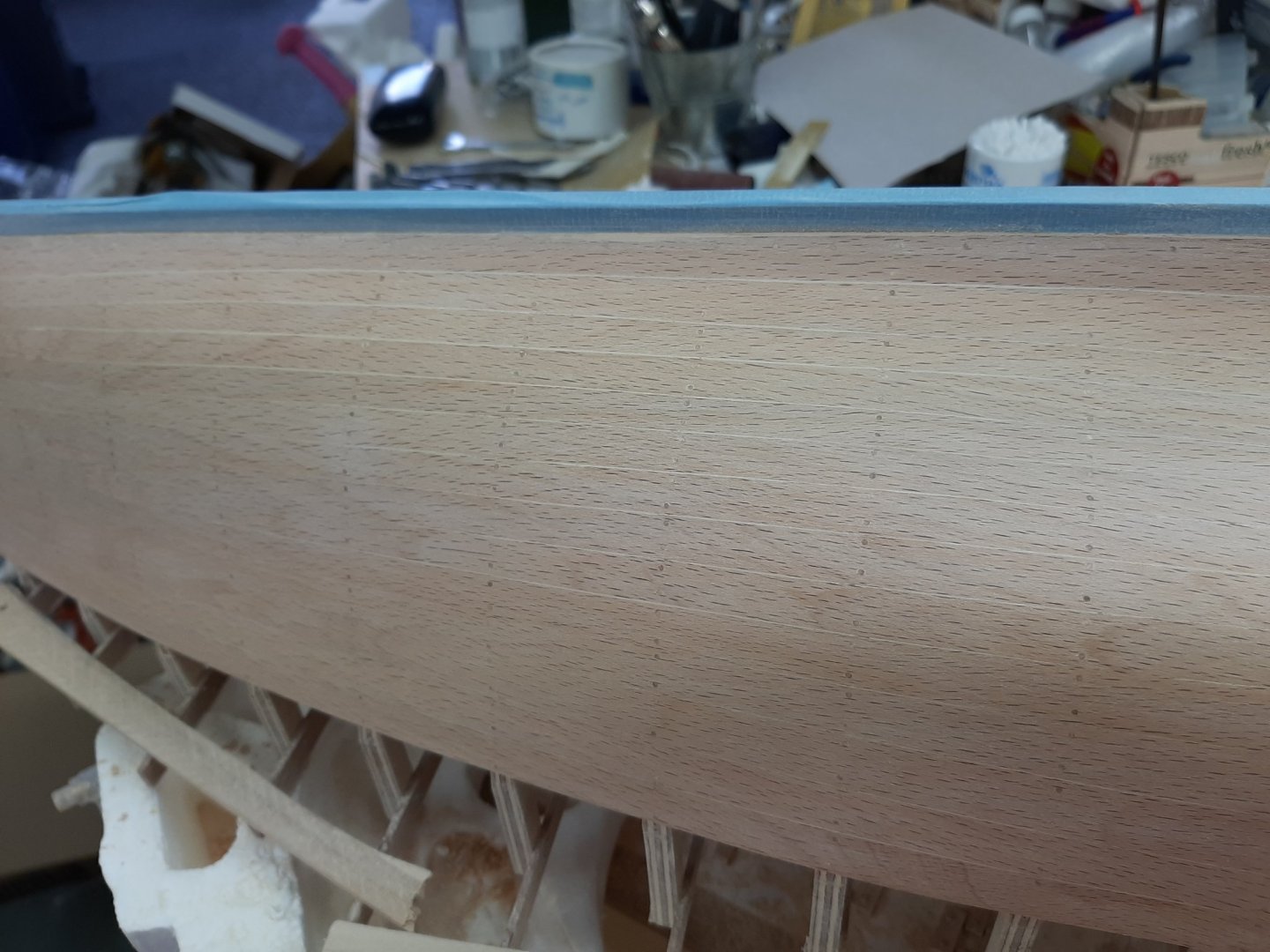
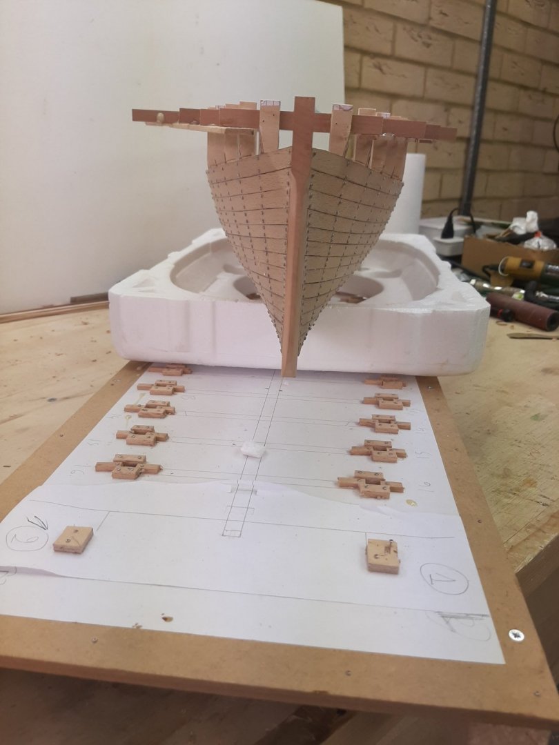
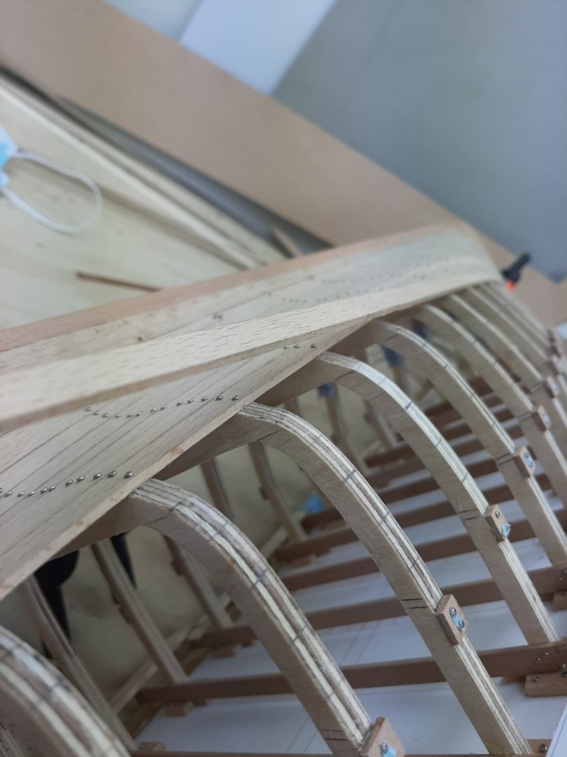
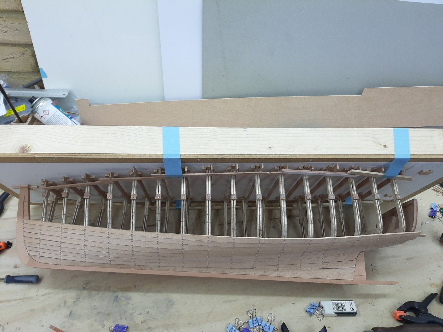
Dear all Many thanks for your likes! GL, after some encouraging testing yesterday, I think I will. Thanks Nils! I ve followed some of your work, really happy you visited! You know something Bedford, I would just come running. Thanks Mark, I am following your half model with great interest. Thanks Michael! The planking is only sanded to 80 grit, there is a lot more sanding to do and many imperfections to fix. Now, these are not moulds, these are the actual frames. The plans call for steam bend ribs but I wanted to use frames-actually, I think Chapelle does mention they can be used. As I have very little time for modelling I had accepted to cut a few corners. So I used less frames than I should probably have used (this worked fine) and used cheap plywood for the frames (this did not work fine). However, the interior will be completely planked and floored so the frames will not be visible. After I bring this hull to a reasonable state, I will probably stop and start the lapstrake planking of the Yawl. This will be a much more difficult undertaking Now, back to the boat, I did a bit of testing to see how Beech and filler react to things. In the next photo, the left side of the test piece has two coats of water based sanding sealer, the left a coat of Tung oil and both are smoothed with steel wool. Photos are very unforgiving but in reality, the filler on the Tung side is almost invisible. I am concerned though that the beech itself will have a blotchy look after Tung oil. I have a few failed planks left so I will oil them and see how long pieces will look. Vaddoc
-
I think I ll contribute my 2 c I tried the PVA-wood dust mix but couldn't make it work. Too dry, too crumbly, did not sand nicely. I much prefer purpose made fillers. I tried mixing Elemers filler with wood dust. Did not work. In my current hull I used Beech and I tried Osmo filler that comes in various wood colours. Very nice to use, only issue it dries really fast. Yesterday, I did a bit of testing, This piece of wood has a groove filled with filler. The left side has 2 coats of a water based sanding sealer. The right side has pure Tung oil on. Both were smoothed with steel wool. On the Tung oil side, the filler is barely visible on the non-forgiving photo but it is completely invisible actually looking at it.

-
Beautiful David, regrettably I missed most of the journey so far. It is amazing how clean and tight the boat looks. Why is the rabet at the stem continuing above the sheer? Edit: just looked at the actual boat, there is more wood to be added.
- 433 replies
-
- 3
-
-
- open boat
- small boat
- (and 1 more)
-
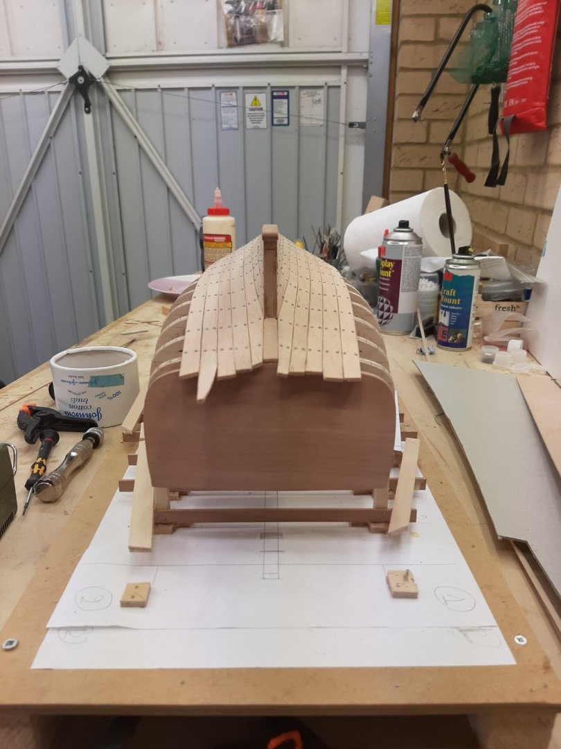
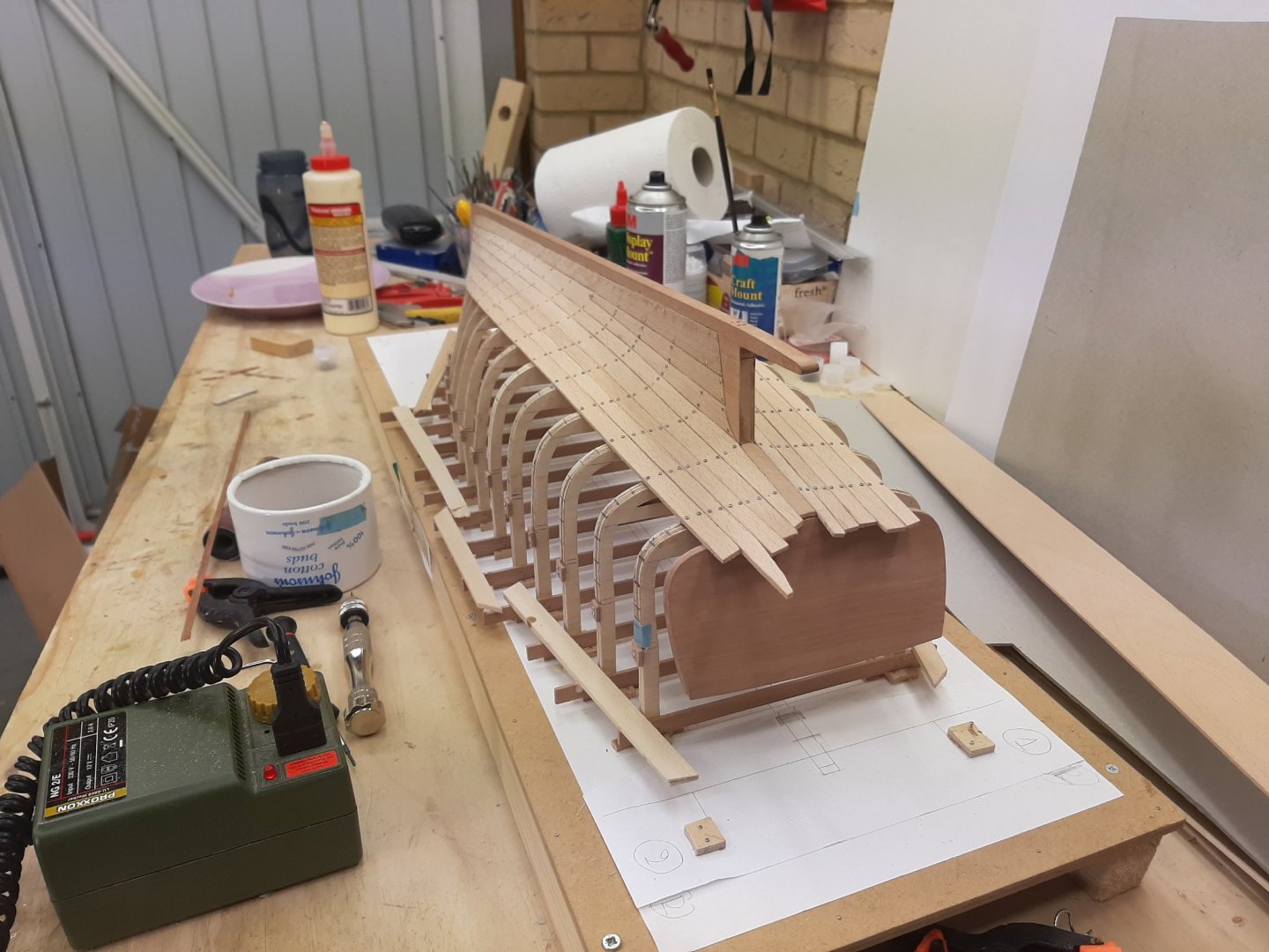
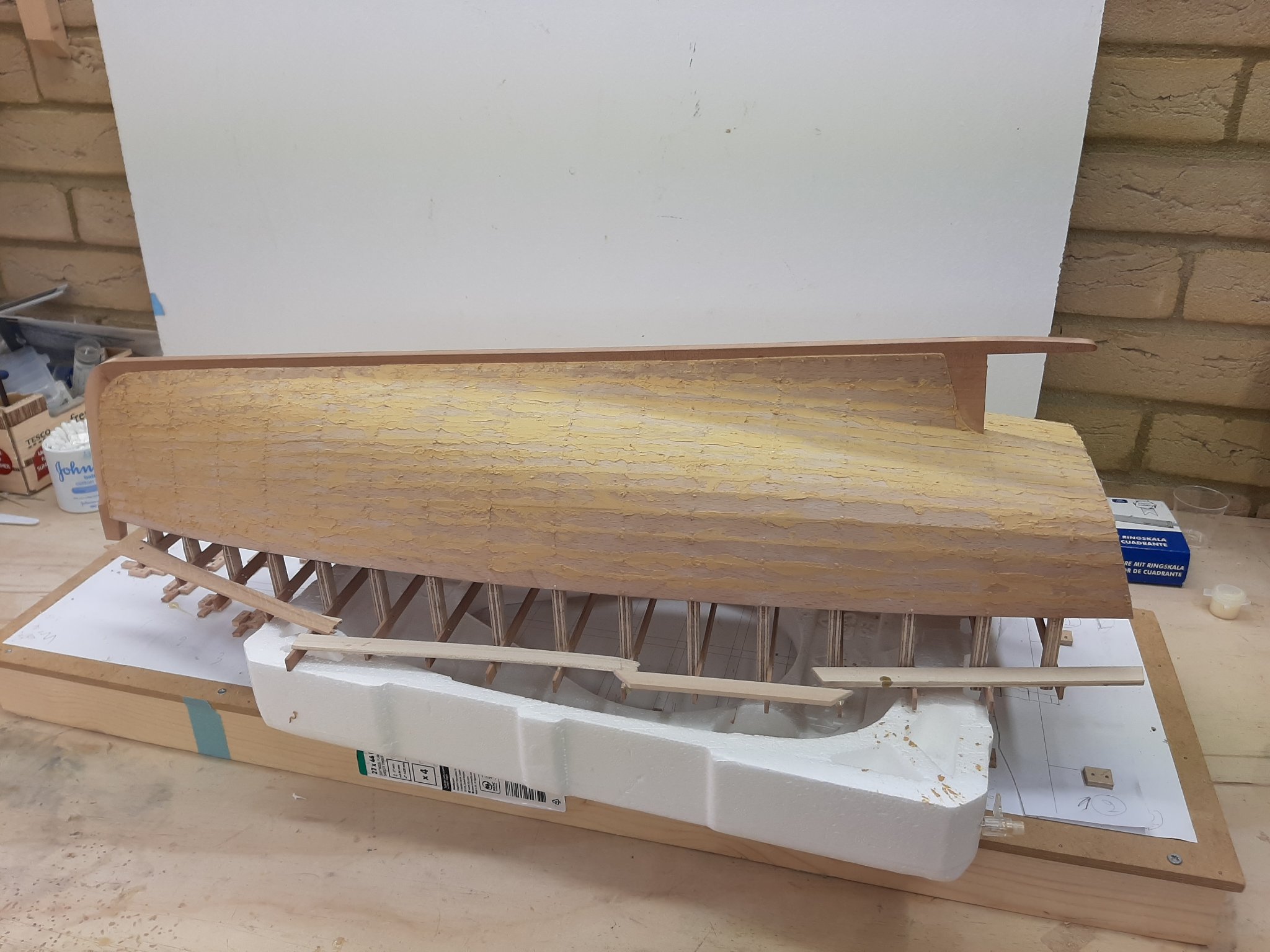
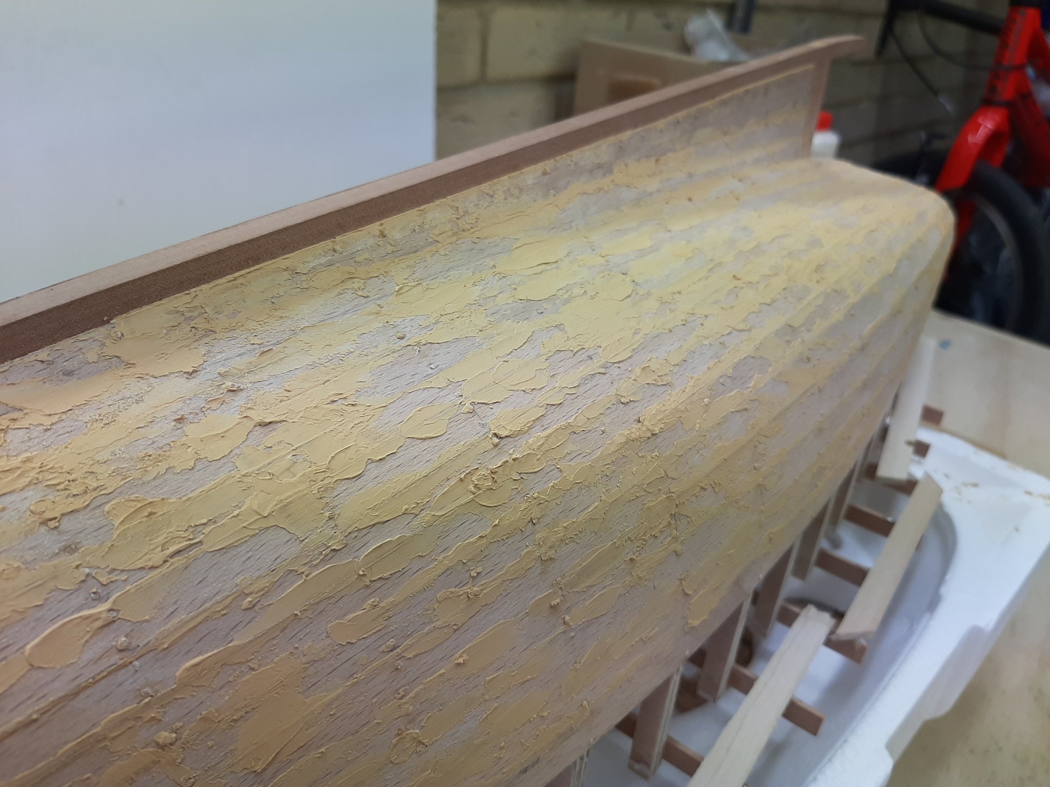
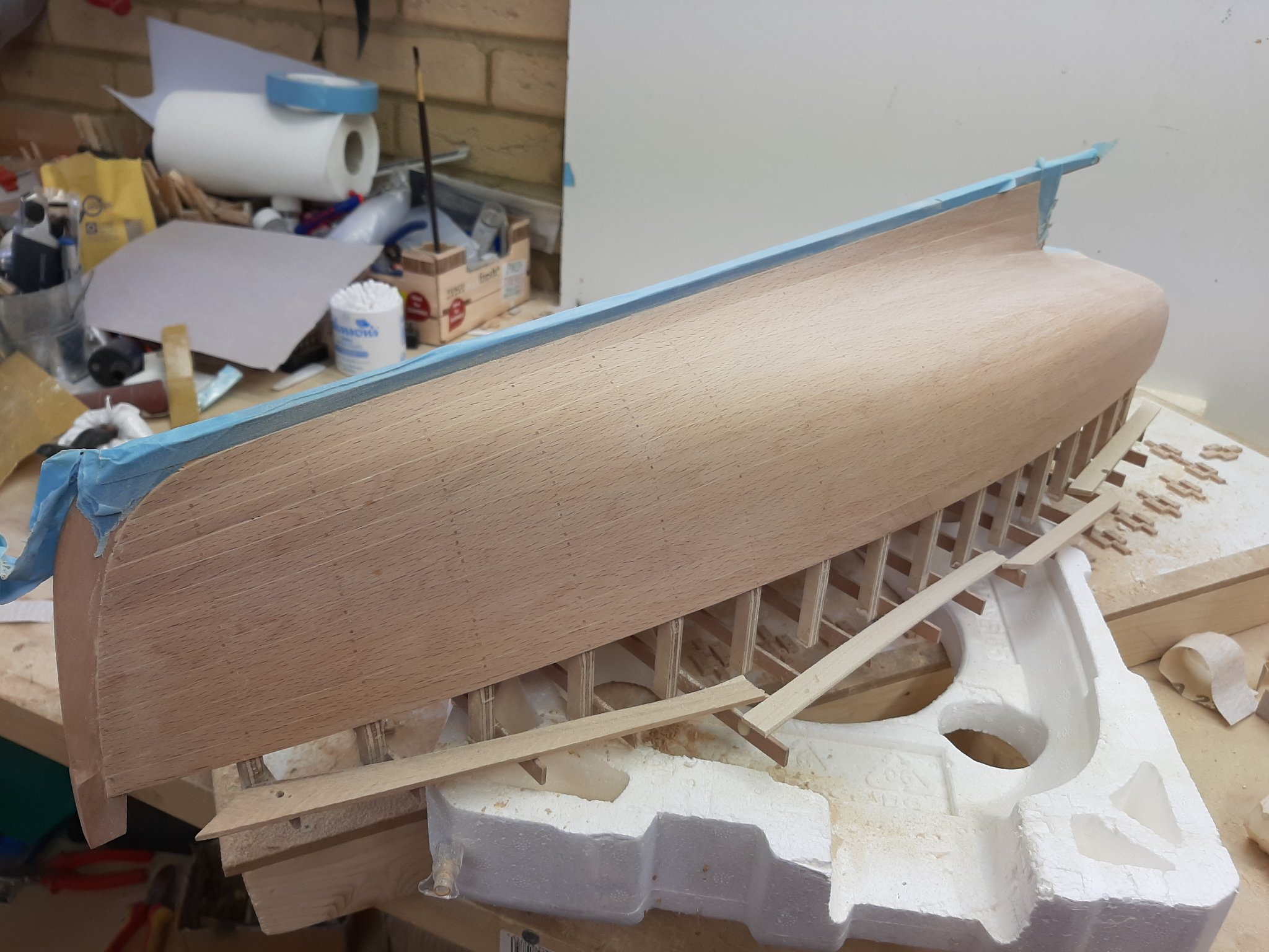
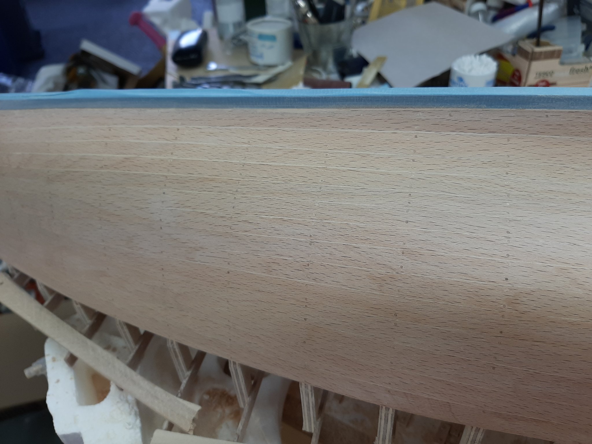
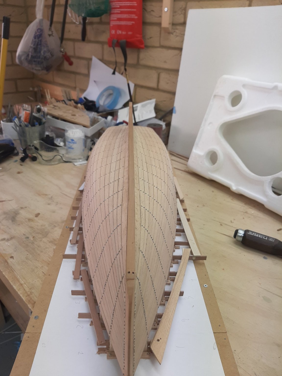
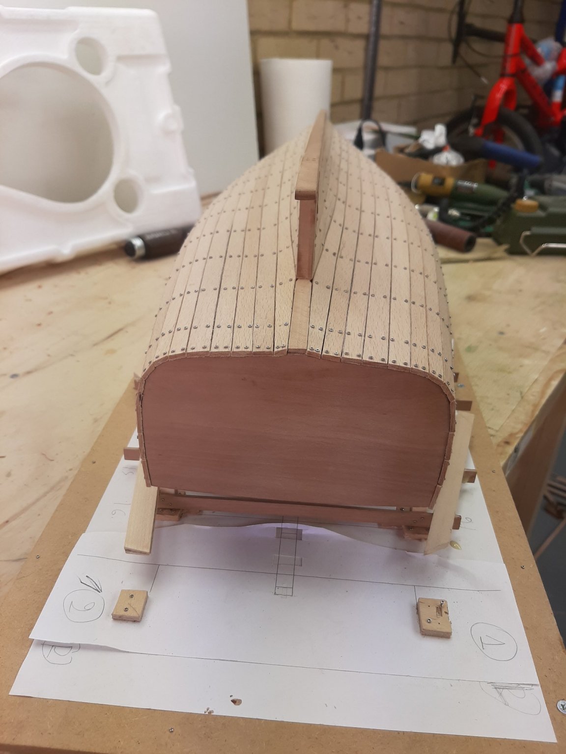
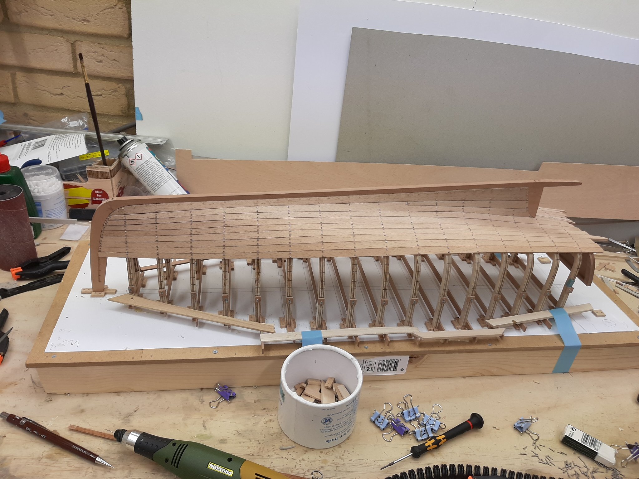
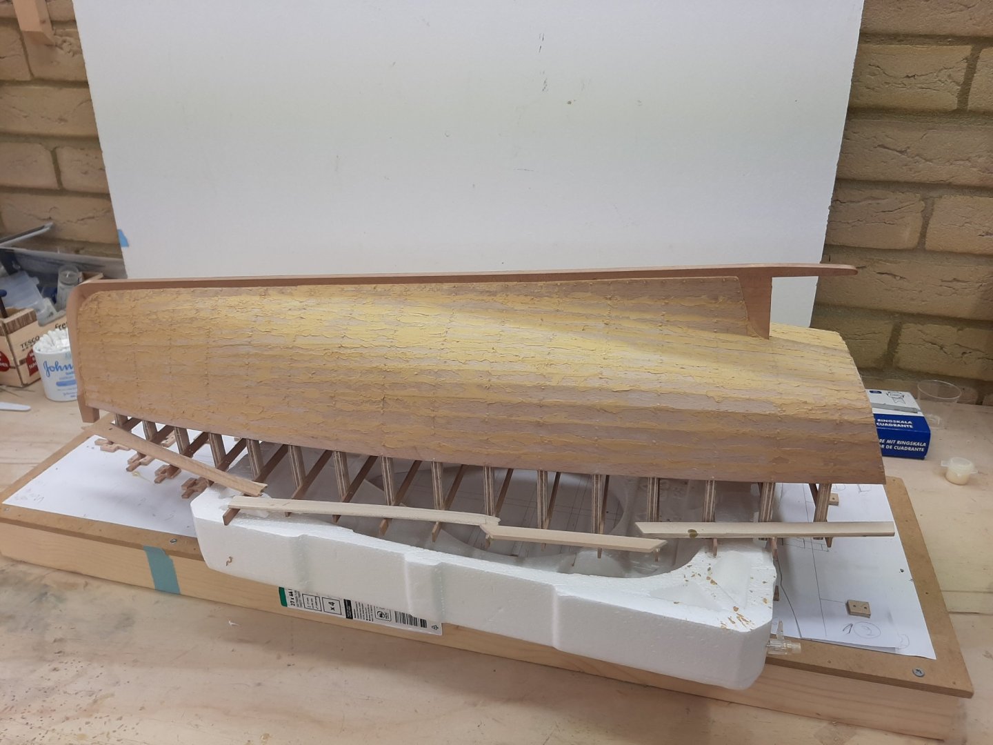
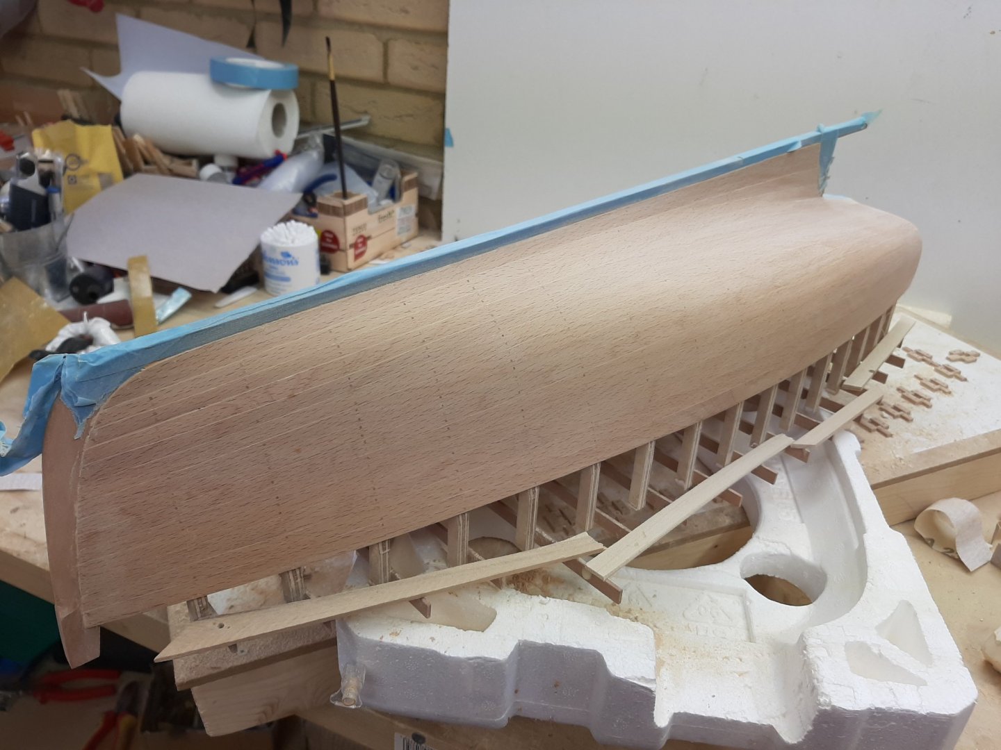
Dear all Thank you for your good words and encouragement. I apologise for taking so long to reply, I simply have had no free time at all. At this time I 'd like to clear a misunderstanding: The Admiral does not have a strong opinion whether the hull should be painted or not. But if it does get painted, she has dictated the colours. So our options are still open! Back to the boat: I replaced all the screws with wooden nails dipped in PVA. It was a good time for this repetitive task, as I was able to work in the house and did not matter how tired I was. I forgot to take pictures though. Then, I filled all the gaps with filler. The larger gaps were also filled from the inside. This time I used Osmo filler, beech colour. I had not used it before. It is ok, it sands fine but it dries incredibly fast. So the hull looked something like this: I only found time to go back to the boat today. So, I started sanding the hull. I used 120 grit initially but then went to 80 grit. After the bulk of the filler was removed, I used carpet knife blades to scrape the excess wood. It went largely ok. Some edges need a bit more attention and lots more sanding with finer grits is needed but it is getting there. The bow needs definitely more work. The gaps do not look too bad and the colour of the filler I suspect will change after the sealer is applied. I may experiment with Tung oil although I seem to remember that Beech does not like oils much. As sanding progresses, a few more gaps will appear that will need filling. Also, before I started sanding I noticed a screw hole I had forgotten to nail. I need to locate it again and put a nail in. Regards Vaddoc


-
Decoart water based sanding sealer. Humbrol spray primer, grey, red, sometimes white. Valejo acrylics, humbrol enamels (very rarely now). Daler-Rowney System 3 brushes. Consistent very good results. With enamels, I use low odour mineral spirits. With Valejo acrylics, only their medium-different for hand painting and spray. For filler, Elmer's colour changing filler.
-
Looking good Hakan! I also think the contrast looks good, maybe a coat of pure Tung oil will blend the two nicely-depends how the wood will react.
-
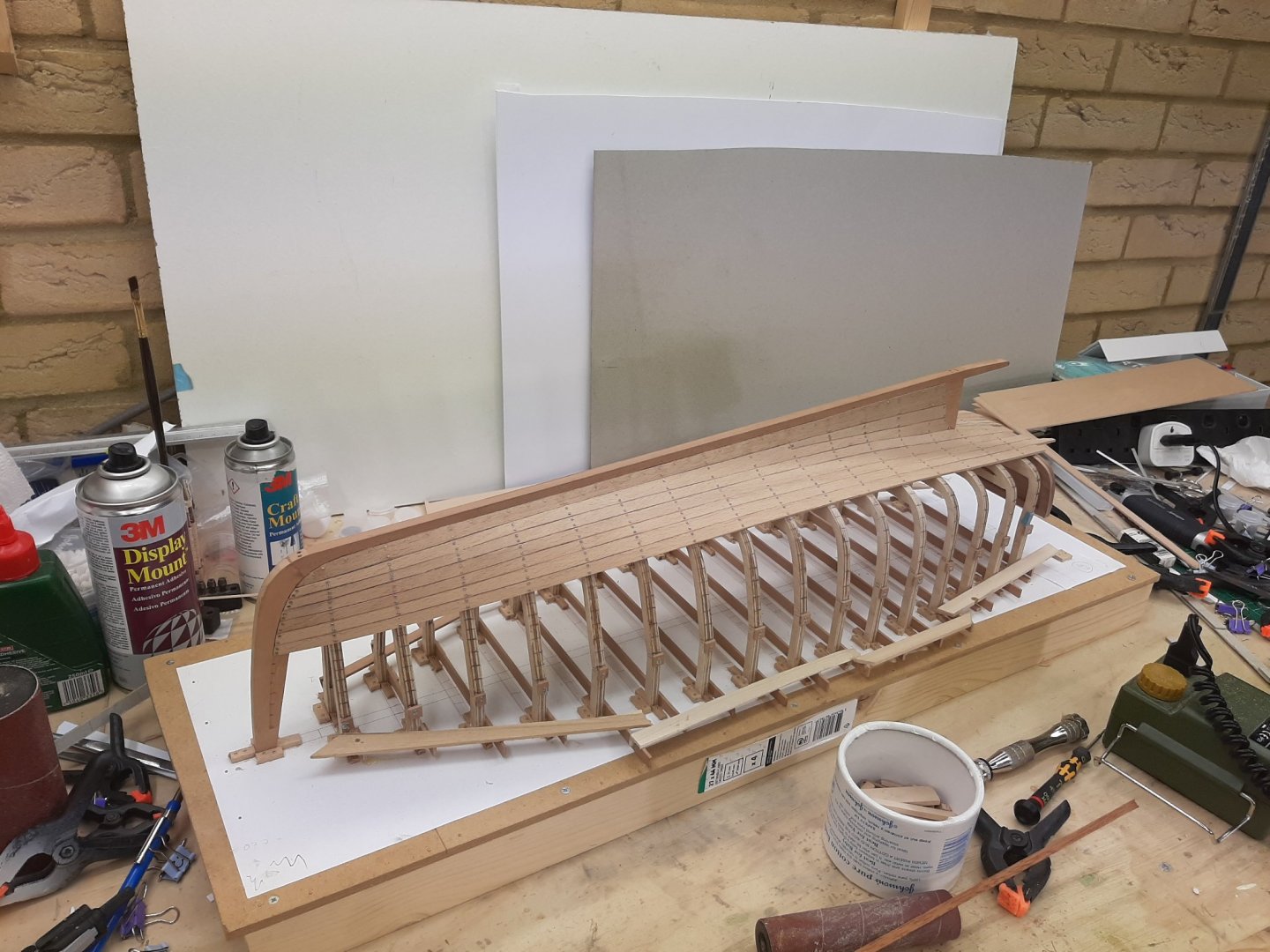
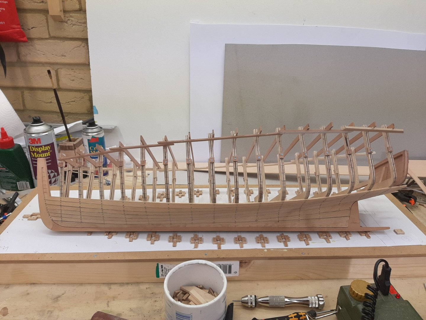
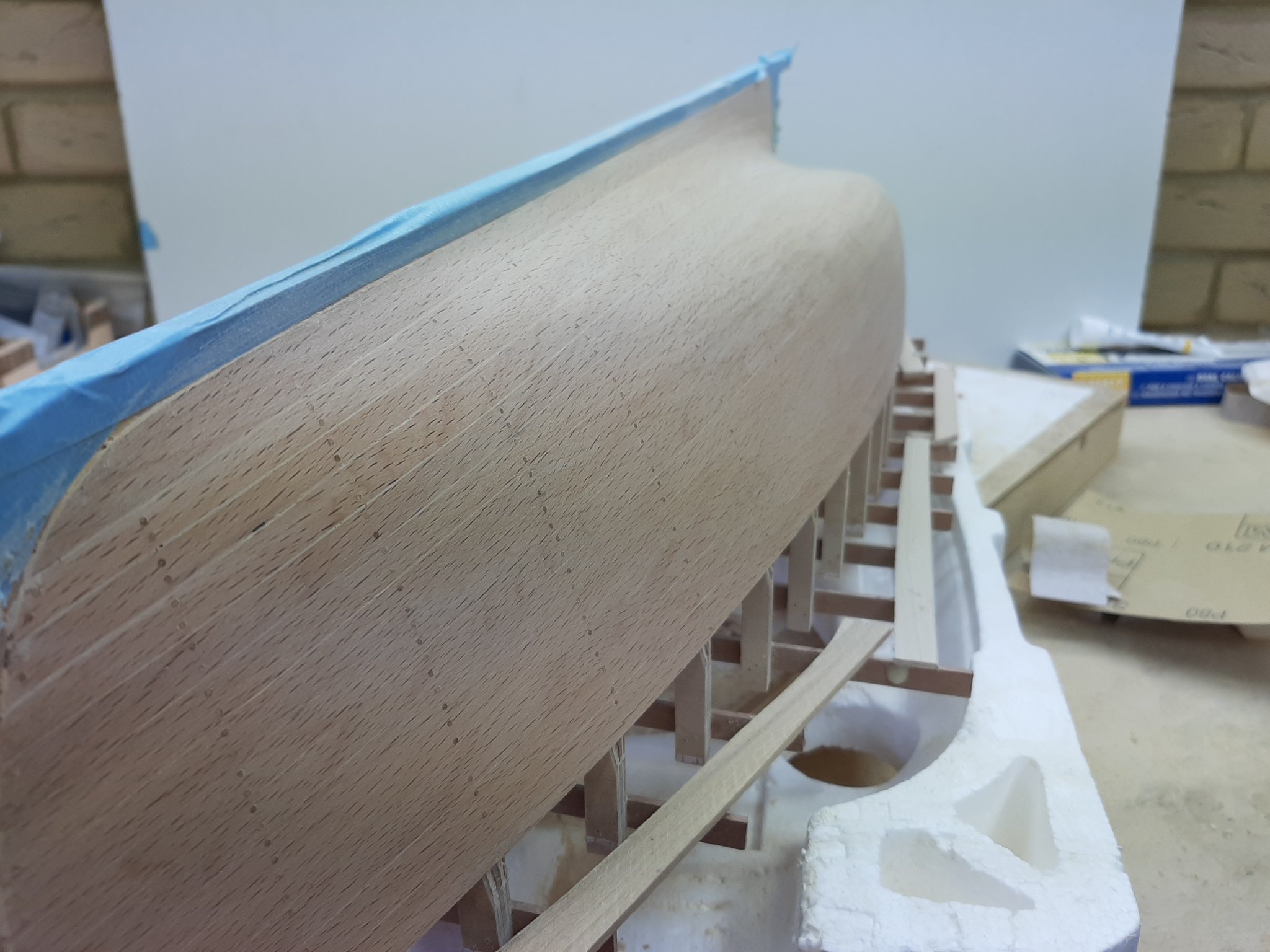
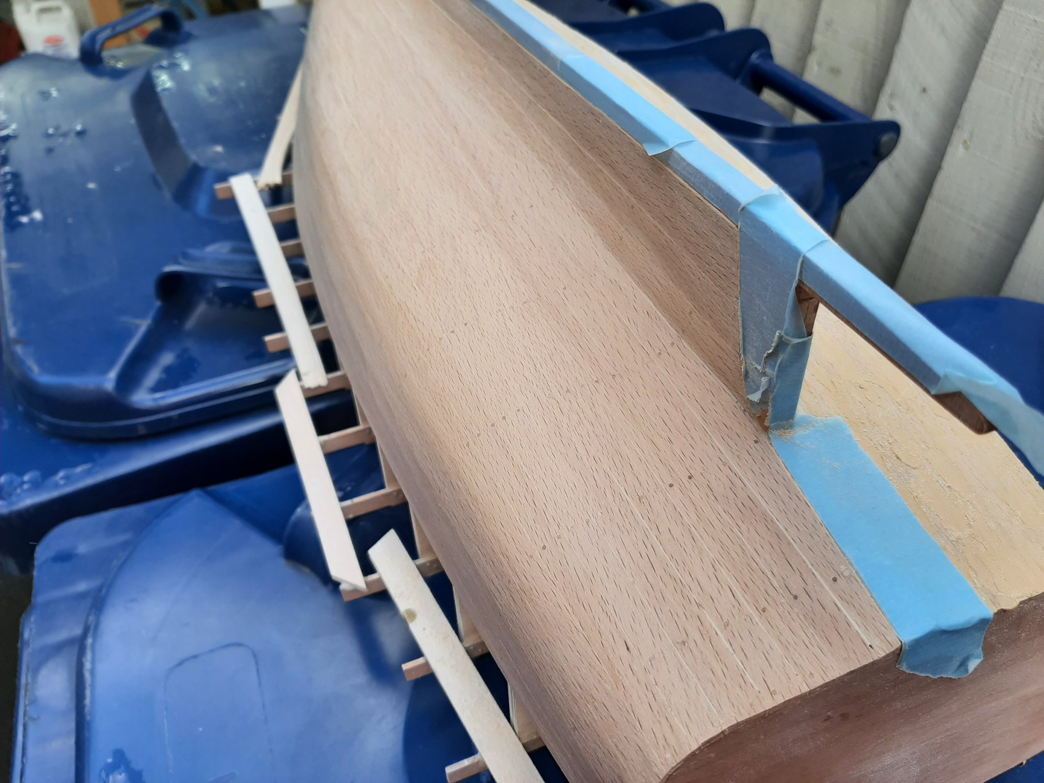
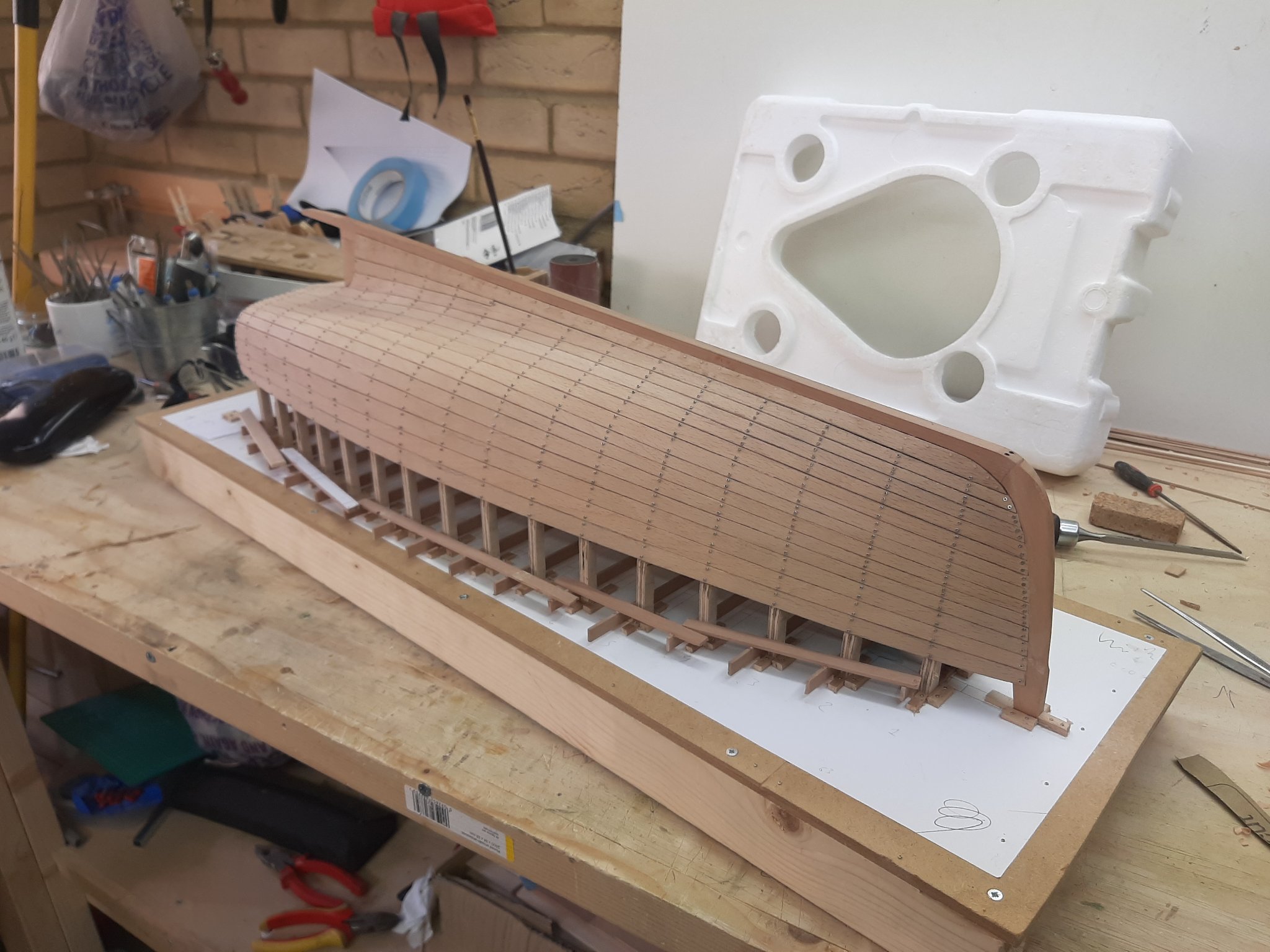
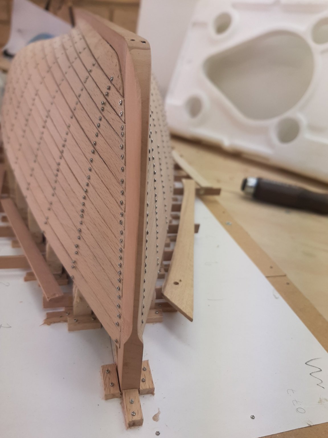
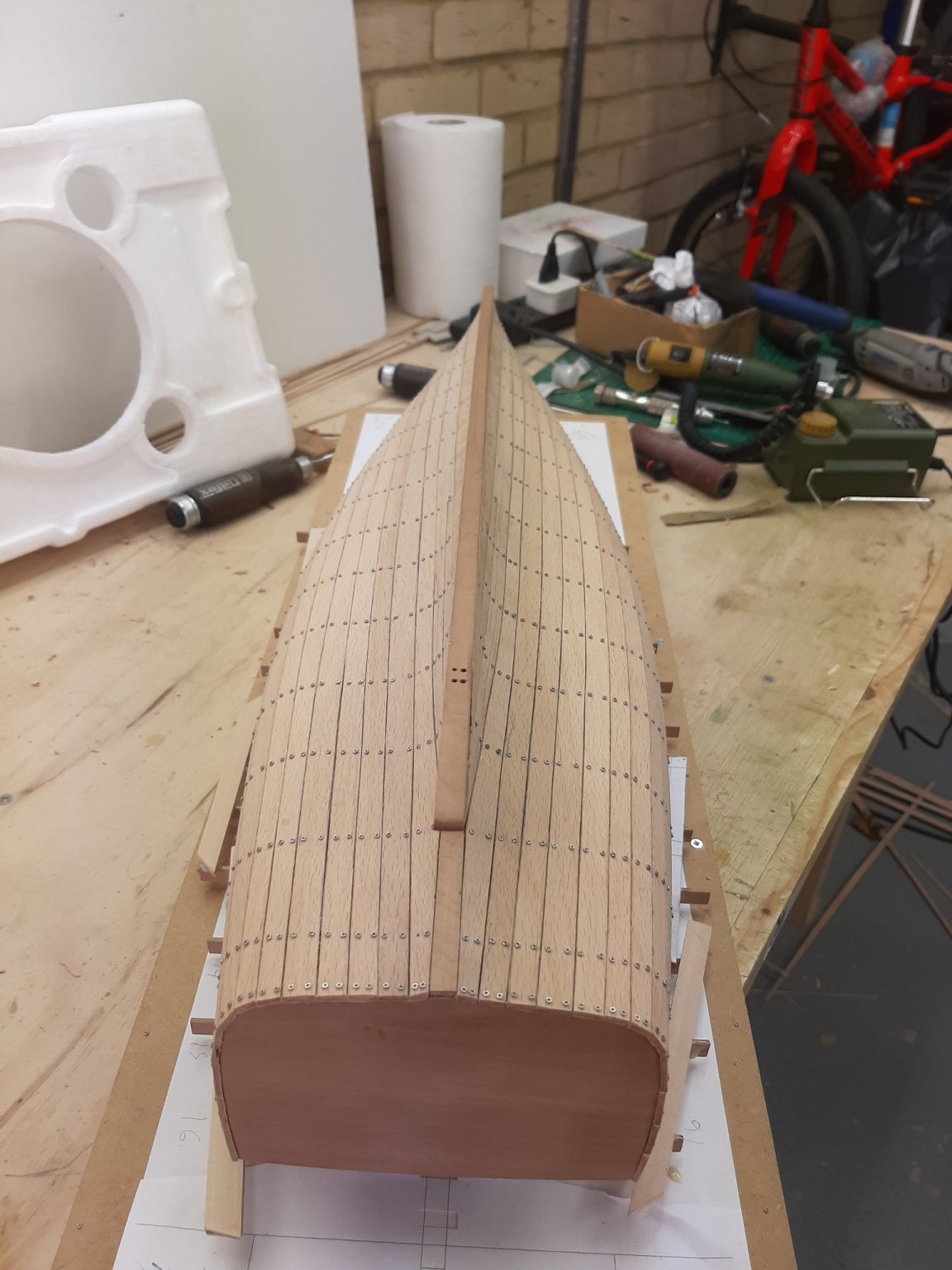
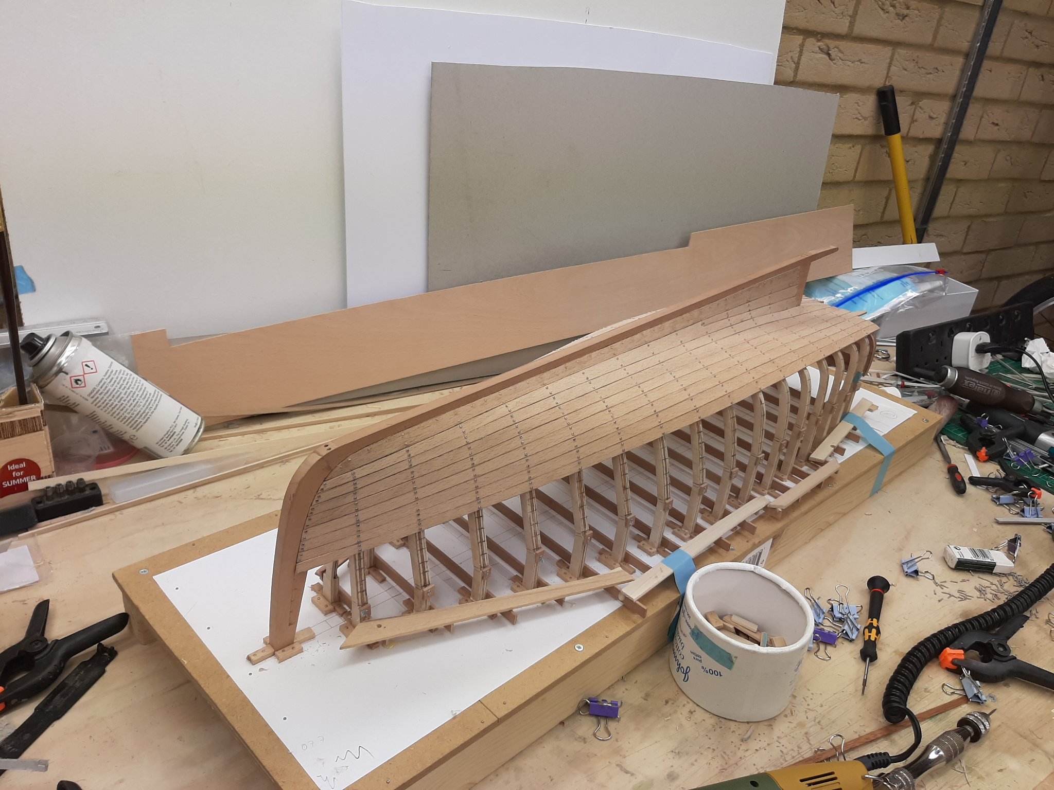
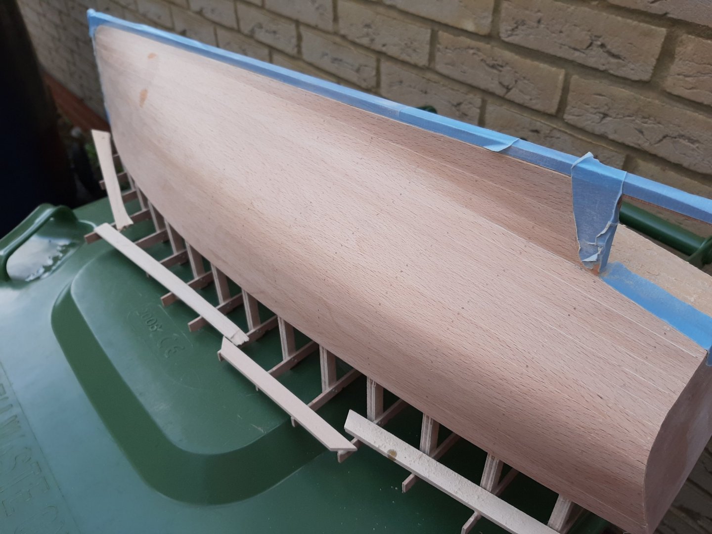
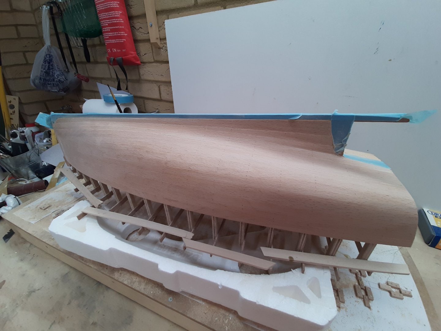
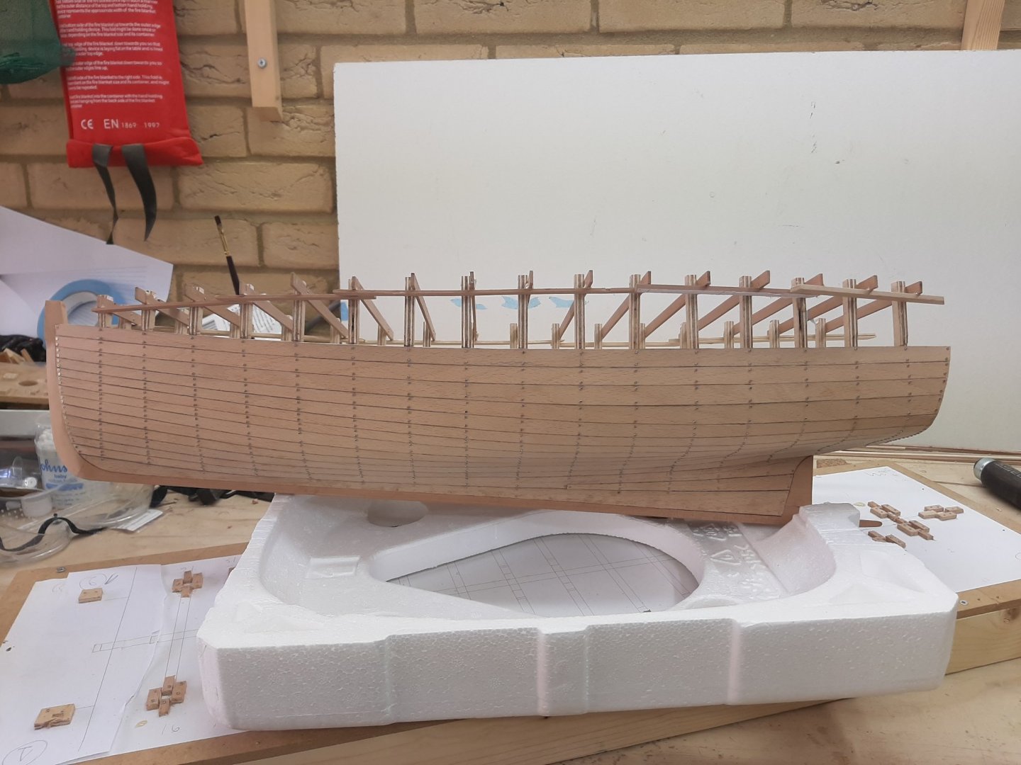
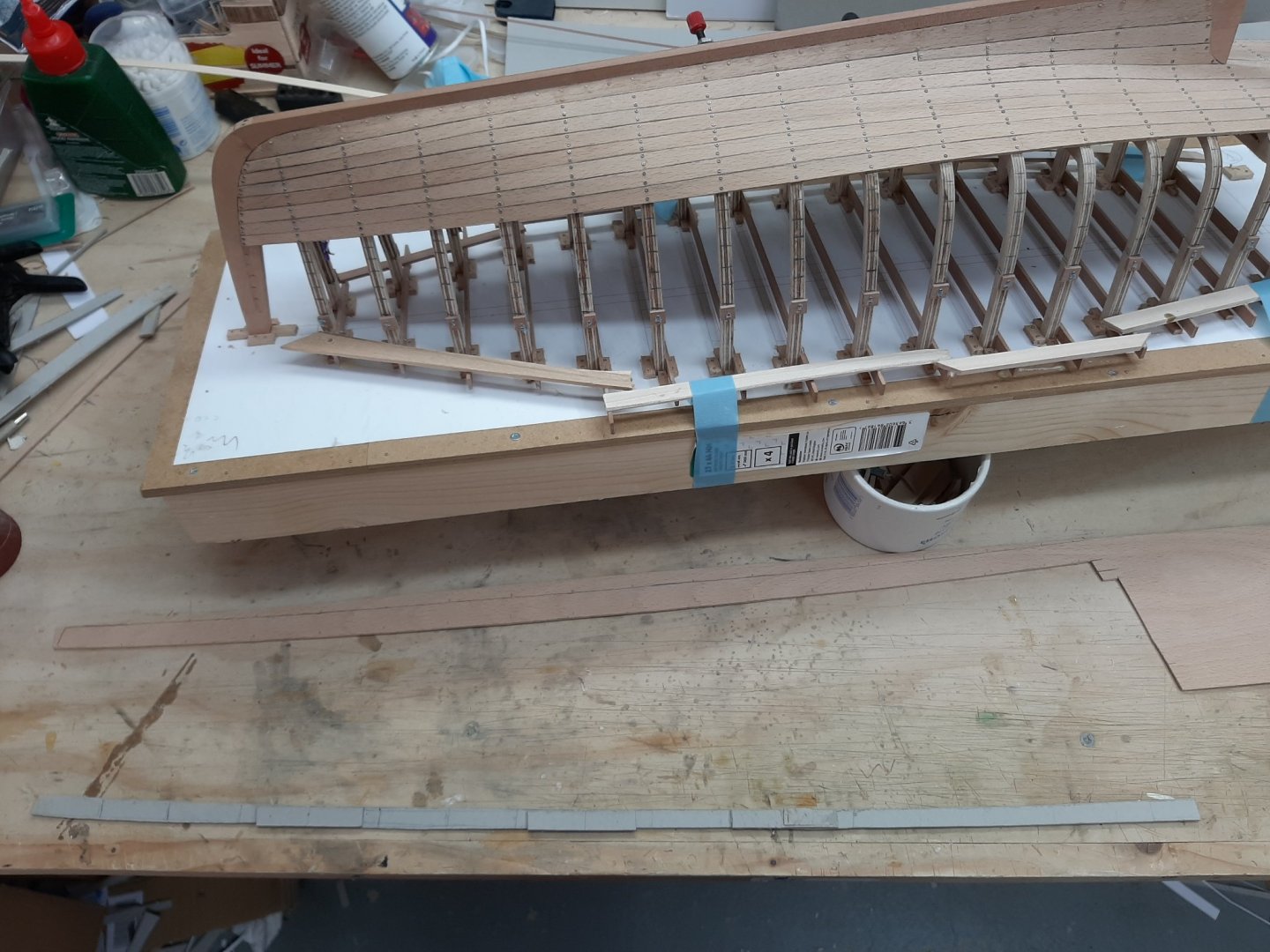
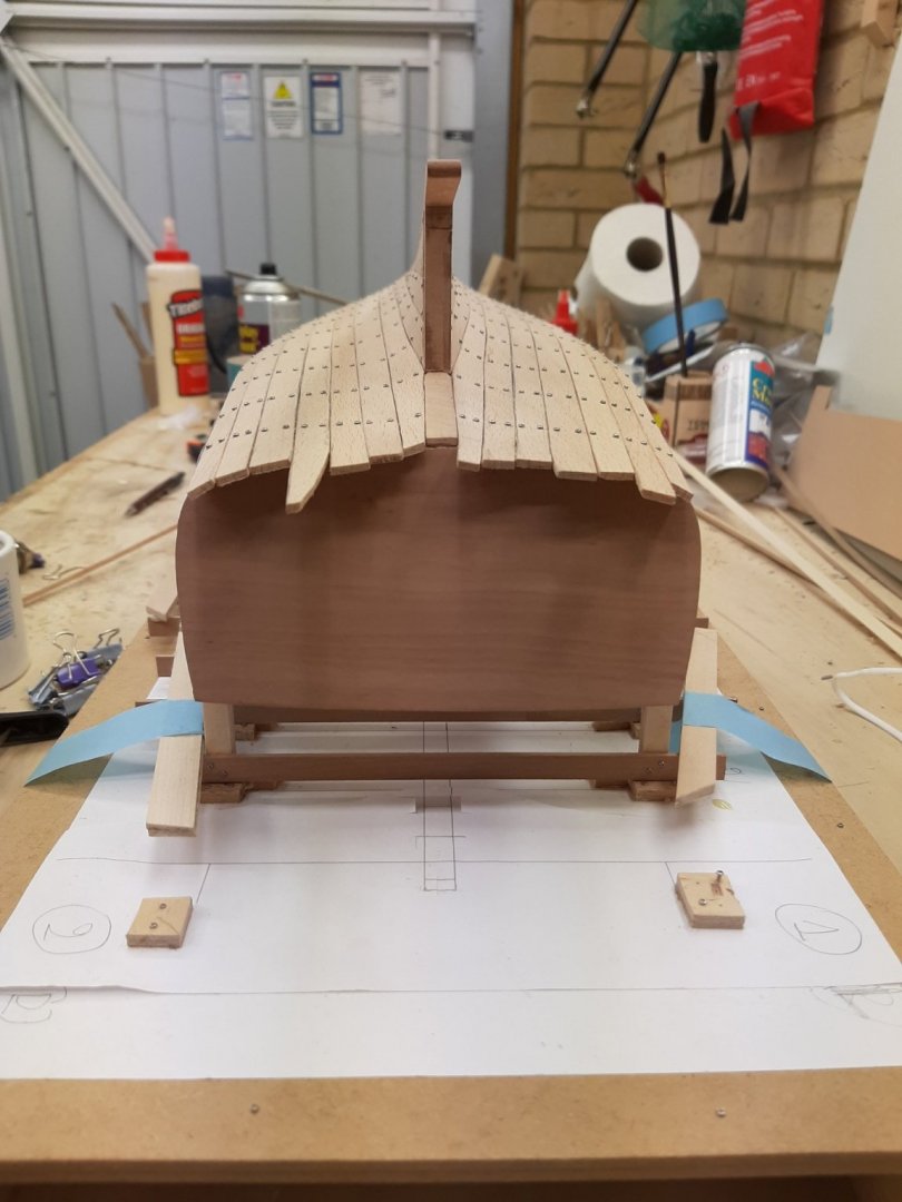
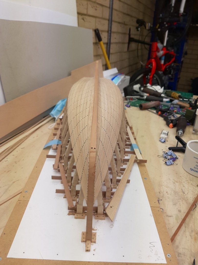
Dear all Planking is finished! I also trimmed the planks at the transom and shaped the stem. John and Bob and to all that hit the like button, many thanks! Keith, whole heartedly recommended. Thanks Michael, following your post I did quite a bit of internet search. I think it really would be very nice to have a model of the Universal 4 in the engine bay. I am not sure though I can pull this off! We ll see! No idea, thanks for the good wards and indeed, you are spot on right. More in the post bellow My dear Patrick! So nice to have you back! Now, I am generally happy with my planking planning. If I was to do it again, I may have used a second stealer or have used an extra plank at the curve of the hull. But overall it is a feasible planking. None of the planks had an impossible curve and the planks blanks were no bigger than 20-25 cm wide, though the sheer plank I think was 70 cm long! My frames were very wrong. Especially the two aft frames were completely wrong and even mispositioned. I had to sim one side and chisel away on the opposite, essentially fairing as I went along. Now you might ask if I had done any fairing before planking, the answer is none whatsoever. I relied on the CAD drawings, on which I did not spend much time and then used plywood which was bending when cutting the patterns. Still, the wood showed me the correct shape and thankfully, my transom placement proved very accurate. My first planks were poorly made. As I was getting into rhythm, the planks improved considerably. I tried to remake the first 2 planks but it was very difficult-I gave up. I regret using a knife to cut the planks instead of sanding them into shape. This caused poor fitting with one another. Also, I regret I did not bevel the first 4 planks where there is the hollow at the stern. These gaps bother me a lot and will get worse with sanding, I hope filler will do the job. Planking the contralateral side created problems due to the wrong frames and some of the planks could have had a more elegant run. I really should have used the disc sander instead of a knife However, I started this boat with the intention of cutting some corners to speed things up and cut costs. I still think it will work! Next, to replace the 850 screws with wood nails and fill and sand the hull. Will I paint it? It depends. If it looks half decent, I ll leave it. If it looks awful, paint will hide all sins! I suspect I ll end up painting it. The Admiral wants red or green bottom with Ivory upper. Regards Vaddoc


-
Retired and ready to build my first model!
vaddoc replied to lraymo's topic in New member Introductions
Welcome and do not worry. Everything eventually falls into place! -
Making Knees
vaddoc replied to Don Case's topic in Building, Framing, Planking and plating a ships hull and deck
From my experience: For dense woods like pear, going a bit across the grain makes no difference, for the loads they ll carry on the model they will be fine. You can laminate two thinner sheets of wood with the grain at 90 degrees so that you can cut in any direction but do not use PVA, the whole sheets will twist horribly due to the water in the glue-use epoxy. Or you can laminate half circles with 0.5 mm strips using epoxy to cut the knees but it is labour intensive, messy and the laminate will be very hard to cut and sand. -
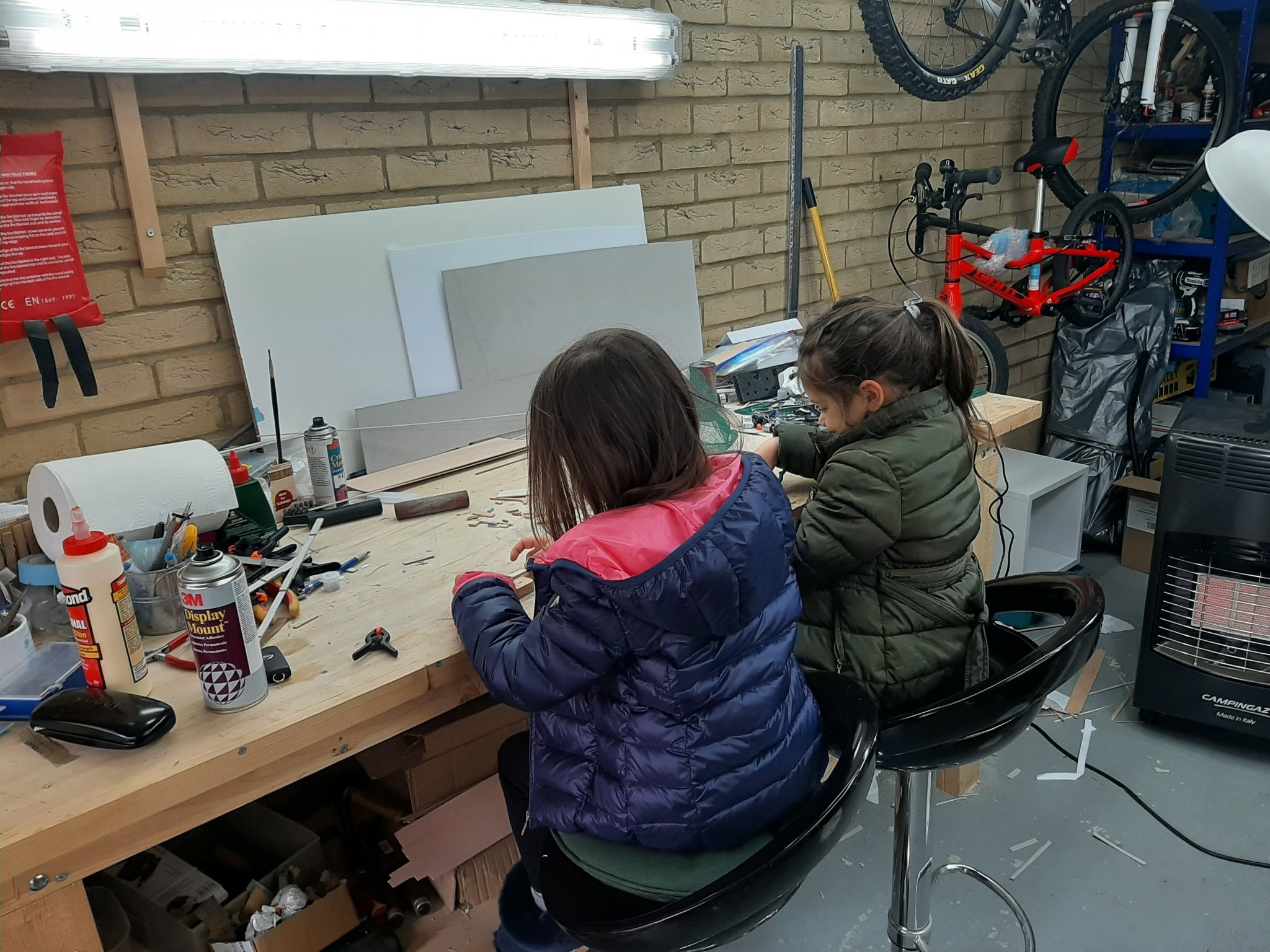
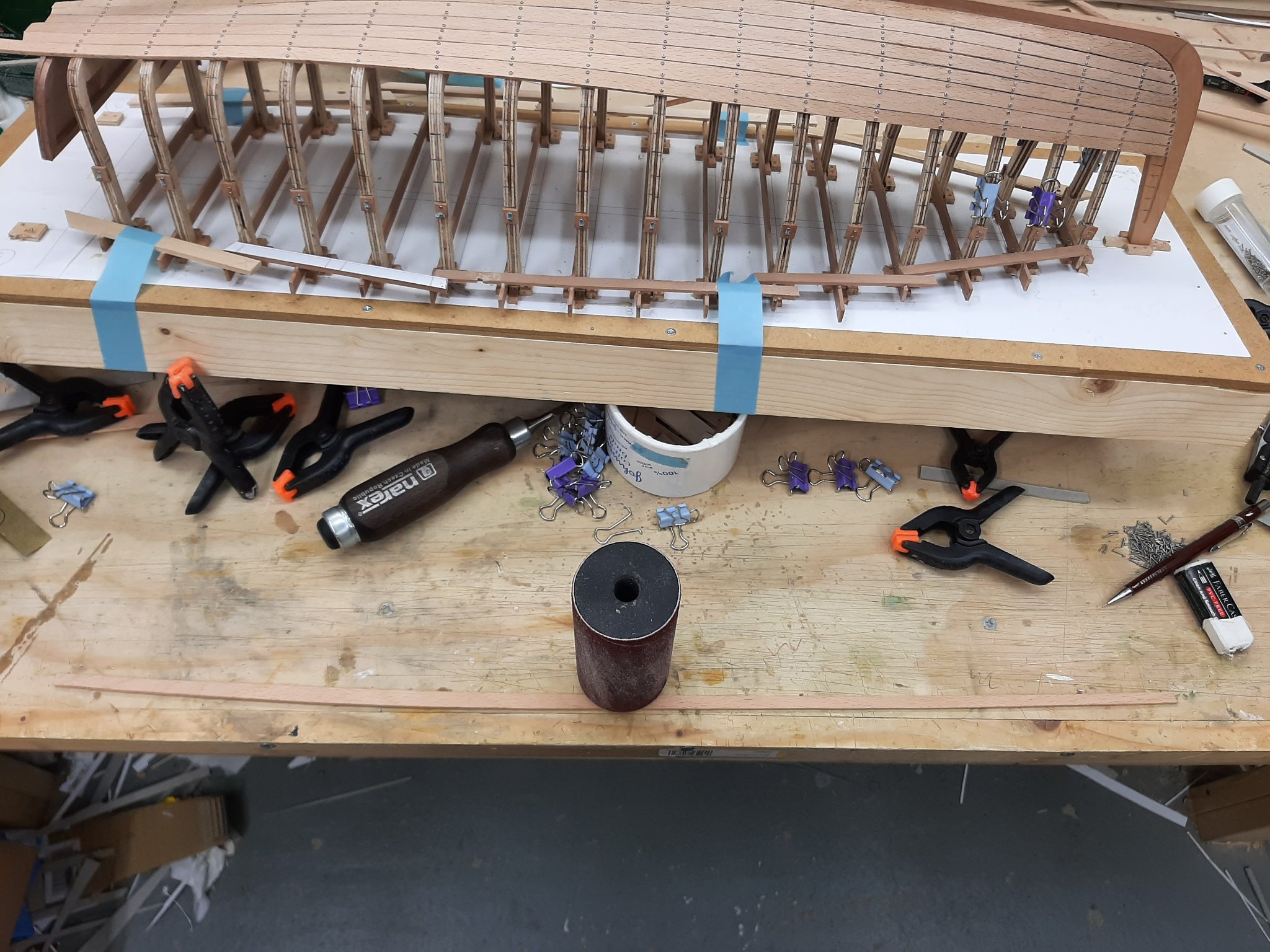
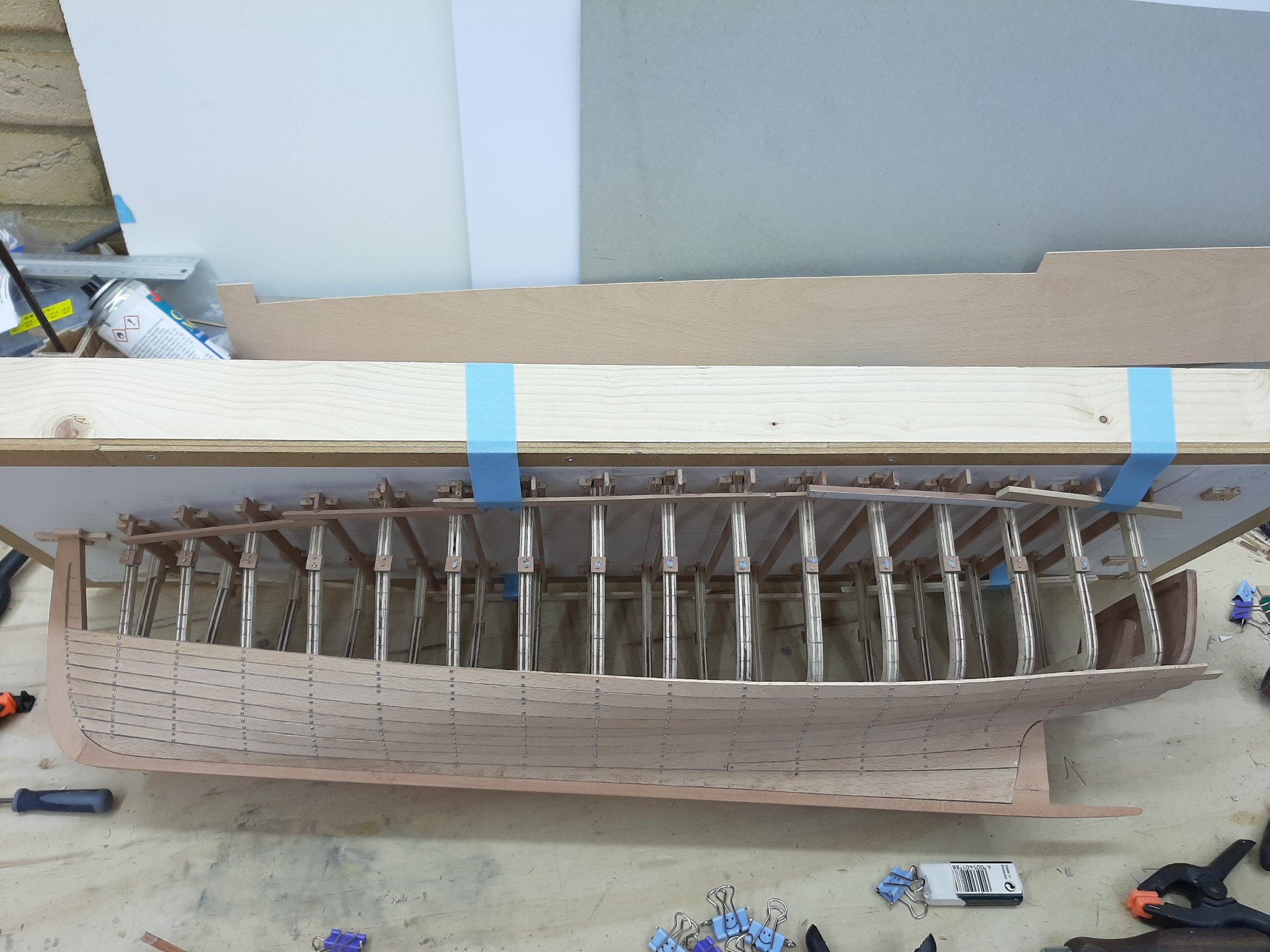
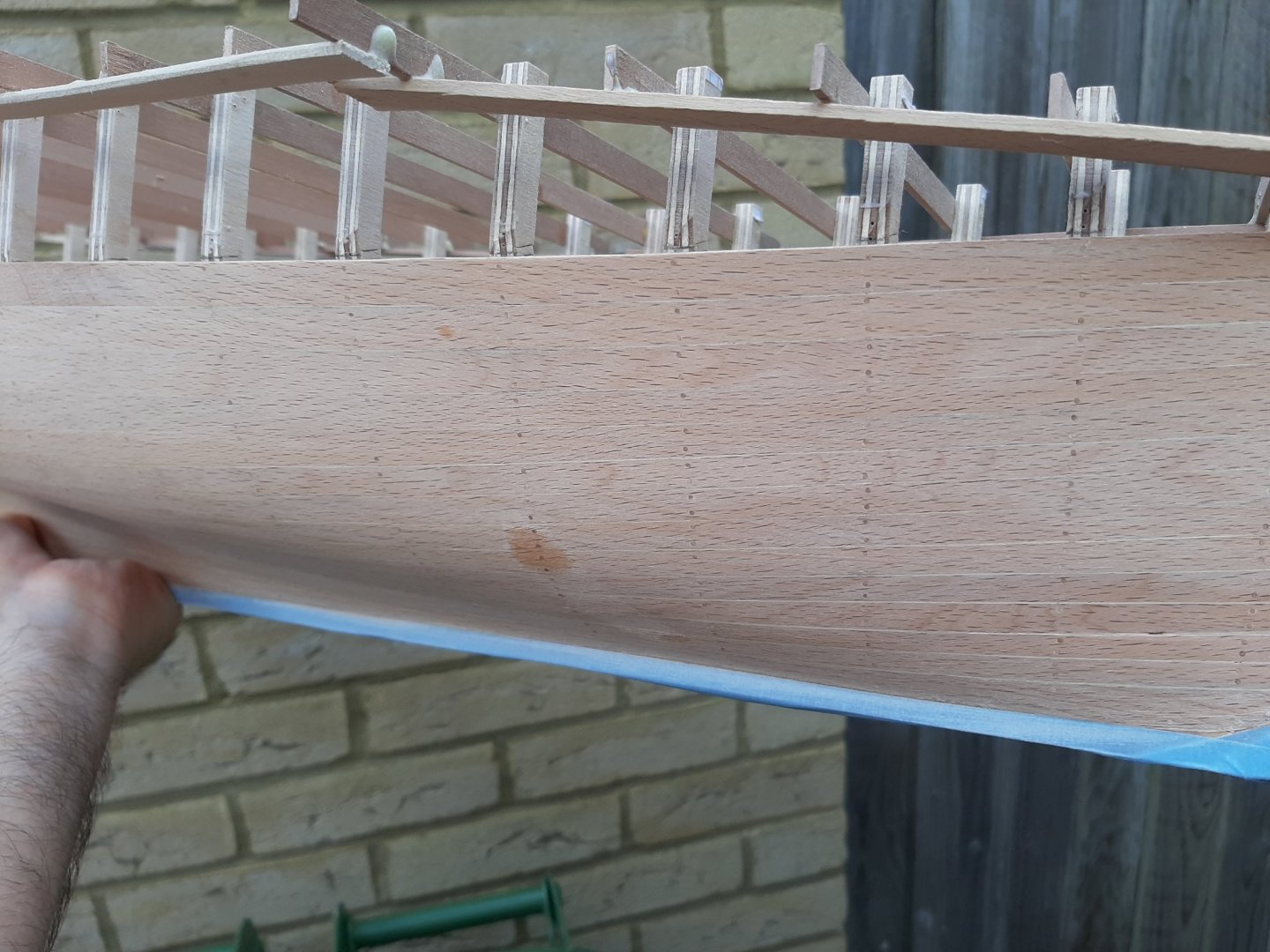
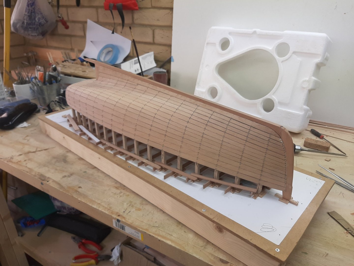
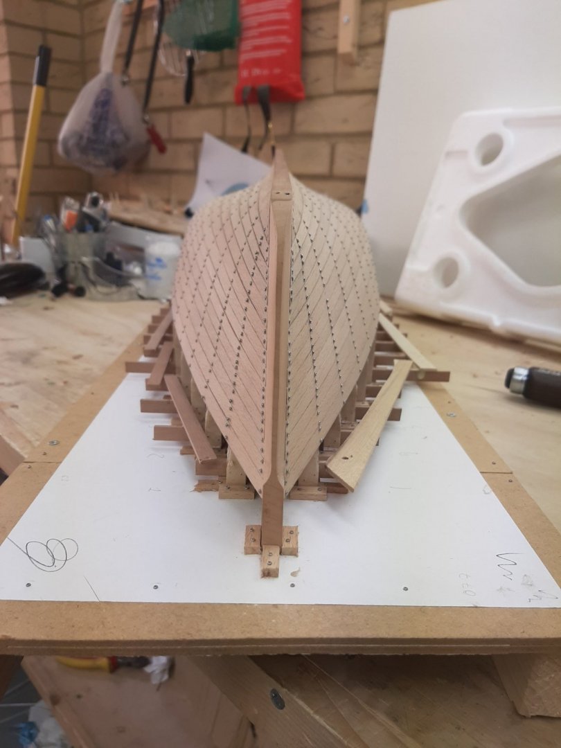
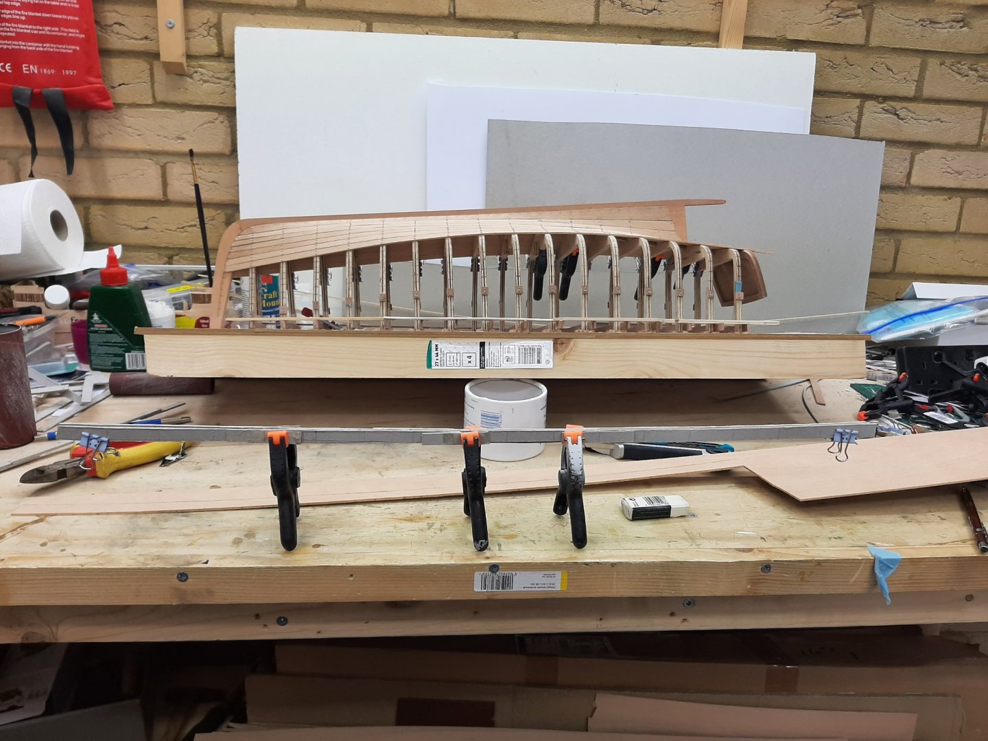
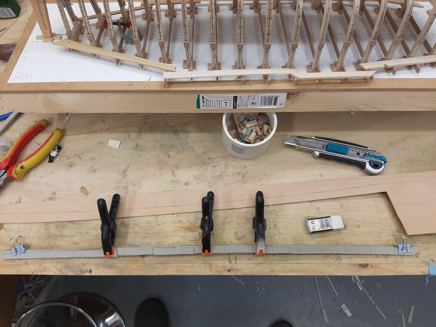
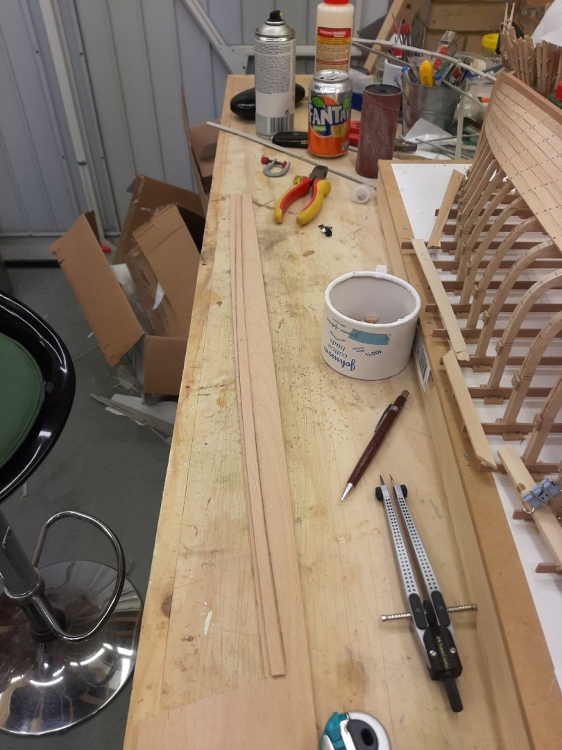
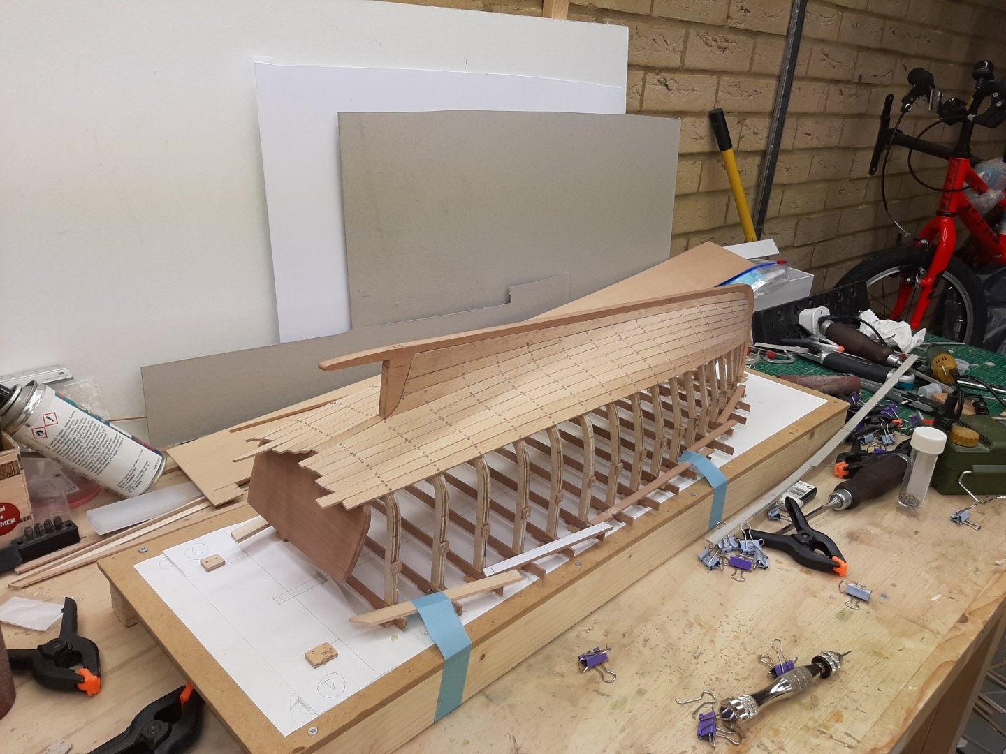
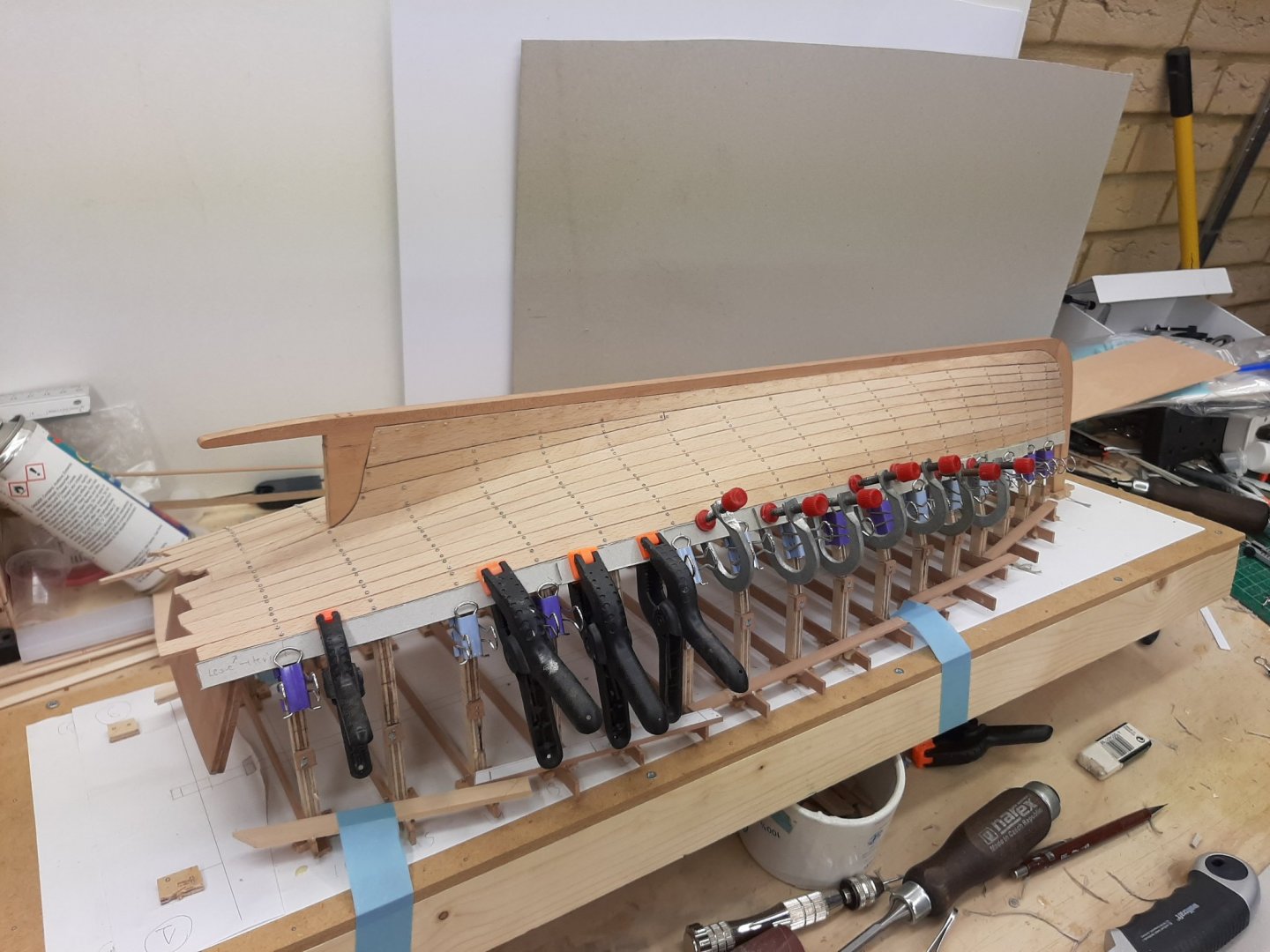
But Hakan, haven't you noticed, I only chose the best angles to get pictures! 🙂 Many thanks. Thanks Gary. Now this boat would be ideal to try weathering for the first time wouldn't you agree? And I know just the log to follow. Something to think about... Thanks to all for your likes! Time for an update on the boat. But before that, just to mention I did put a few batens on the Yawl. Oh dear...it will be a difficult planking job with lots of steaming! Also, I think I should reveal my secret on planking. I have 2 little elves helping me! So, I started work on plank No 8. At this point, the planks on both sides are almost identical, this is a good sign. These are the patterns from both sides clamped together. The previous planks were actually the most curved, the planks now are becoming straighter. I am happy with the initial planning. And these are the two No 8 planks one on top of the other-almost identical. So then I moved on to No 9. Again, the spilling is not unreasonable. However, this is a tricky plank to fit. There is much less of a twist so it is easier to make the pattern but this plank goes on the most curved part of the hull. The planks will not sit unless their edge is pretty bevelled but also their underside hollowed. I am ashamed to admit I found easier to just chisel the frames flat! The next photo shows how thick the planks are. Both planks went in quite easily. Two of the aft frames are very wrong and need shimming and a few others had the wrong bevel. It is pretty easy to tell actually, the planks at 2 mm are very thick and immediately show the problem areas. A few pictures of the planking so far. They are taken from quite far due to the size of the boat. And on to the next. I have been reusing pieces of the previous cardboard templates and with the plank twist getting less, the process is speeding up. The planks though are getting pretty long, I guess this one is around 65 cm long Regards Vaddoc


-
GL, the differences between the frames as given and the lofted ones are pretty dramatic. Now, this is why we loft before building but with the accuracy in CAD era, everyone's lofting should not be that far apart. Strange.
- 153 replies
-
- 2
-
-
- Ancre
- Bruno Orsel
- (and 2 more)
-
We really need you fingers Michael, not your files! This is looking proper Moab. Congratulations! The wood jig is a good method.
-
Indeed Roger. This actually was what the Mediterranean shipwrights were also doing. I have no expertise or knowledge in this matter but what I meant was that, after the frames were produced, whether perpendicular to the keel or waterline or other, these angles still had to be maintained building the boat so the shipwrights would have to know beforehand how the boat would lay for building and how it would go in the water. I assume that those very heavy frames would make sense to keep vertical and not at an angle where they would need pretty substantial support.
-
I would think: The construction should follow the plans. If a frame is meant to be perpendicular to the keel. it must be placed as such. Even a few degrees off in a long frame will lead to problems. The shipwrights would need to think of a way to get the ship to water but keeping the frames as per plans-perpendicular to the keel. EDIT: or perpendicular to the waterline like my current boat that has a sloping keel or whatever the plans show
-
Brian, wonderful work! Certainly inspiring and is great fun following your log. I ve never used or even touched styrene but seems a very versatile material. Really, your boat looks seriously good.
-
GL, I tried to find some info on silk sails but couldn't. Do they make such a difference in performance?
- 153 replies
-
- 1
-
-
- Ancre
- Bruno Orsel
- (and 2 more)
-
Not too late I hope GL, this is a nice boat! Your sanding bow and method is a great idea, I should have seen this earlier before I make such mess of my frames. I am curious to see how you will laminate the frames. I would think that it would be easier to laminate and then sand the bevels. Also, are you going to use PVA or epoxy? My attempts laminating with PVA faired poorly, the laminate was just not stiff enough.
- 153 replies
-
- 2
-
-
- Ancre
- Bruno Orsel
- (and 2 more)
-
Valeriy I am late to the party but I just read all 17 pages of your log, to catch up. Truly exceptional work. Too much to take in! The precision of your work is mind blowing.
-
Moab, I share your problem. Essentially, how to work metal without proper metal working tools, that is a lathe and all the needed accessories and skills. I honestly think it cant be done. I tried also using the Dremel, files and sand paper to shape brass and copper. Failed miserably and burned my fingers. Maybe use another material and use metal paints?
-
Now Michael, how about that Skipjack and its lovely engine and gearbox, this is certainly on hiatus. The boats will not build themselves you know. The barbarians at the gates...😁
-
Thanks Flying Fish! Yes, the width of the planks over the most curved parts will be (hopefully) 8 mm which I think should be fine. The planks will need to be heavily bevelled though.
-
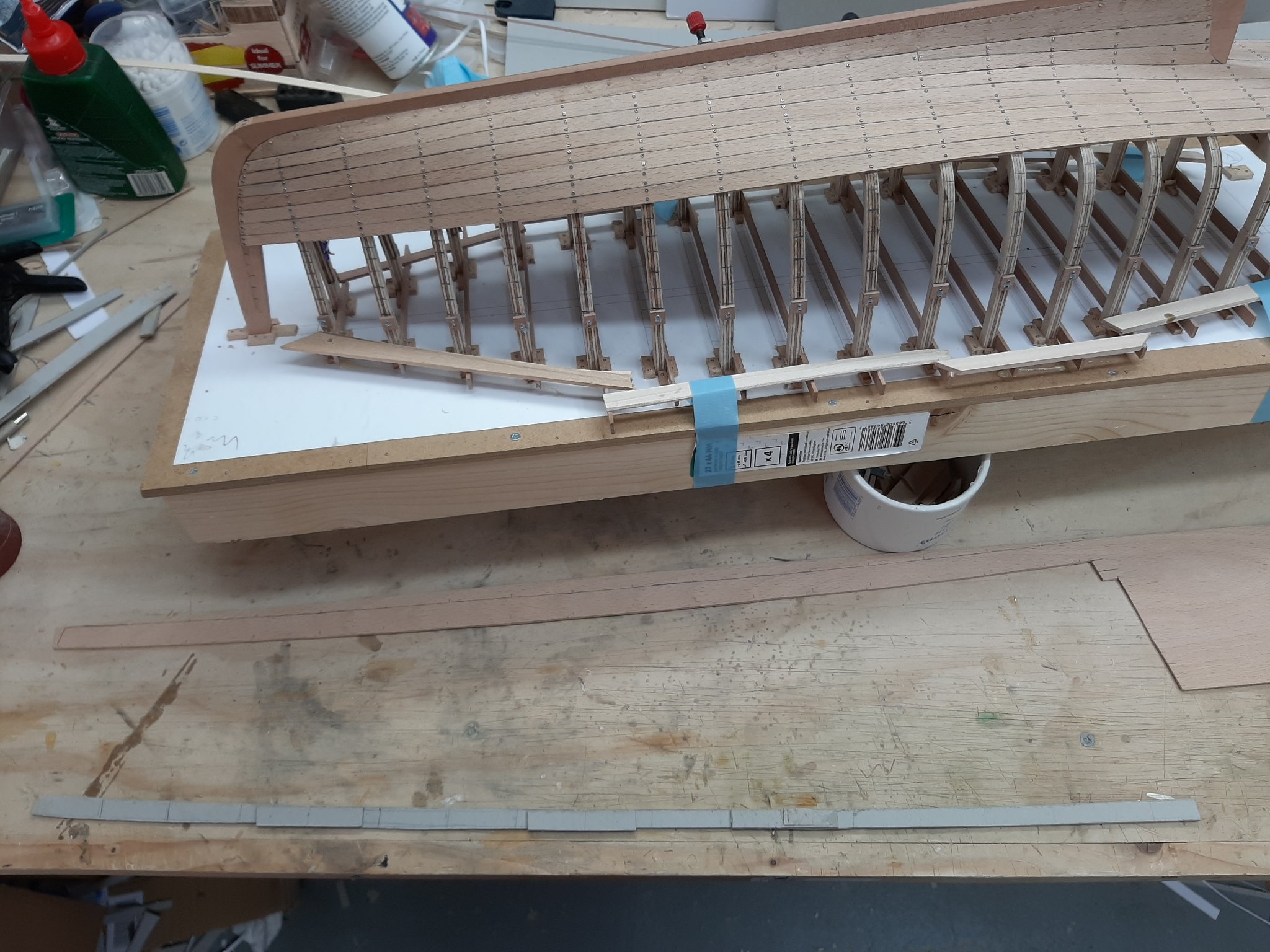
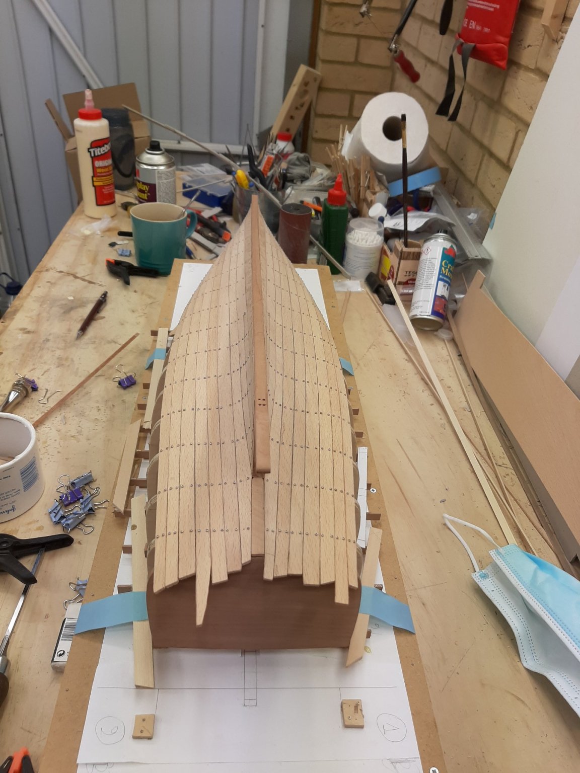
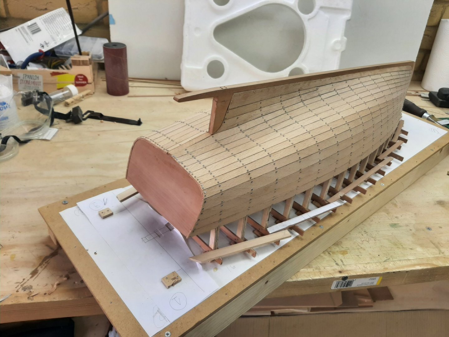
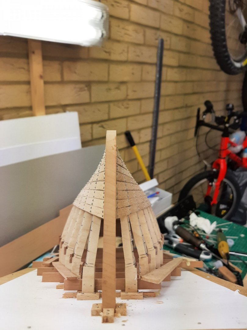
I thought I d just post a few more pictures. Half way through the outer planking!