HOLIDAY DONATION DRIVE - SUPPORT MSW - DO YOUR PART TO KEEP THIS GREAT FORUM GOING! (Only 13 donations so far - C'mon guys!)
×


robdurant
-
Posts
842 -
Joined
-
Last visited
Content Type
Profiles
Forums
Gallery
Events
Everything posted by robdurant
-
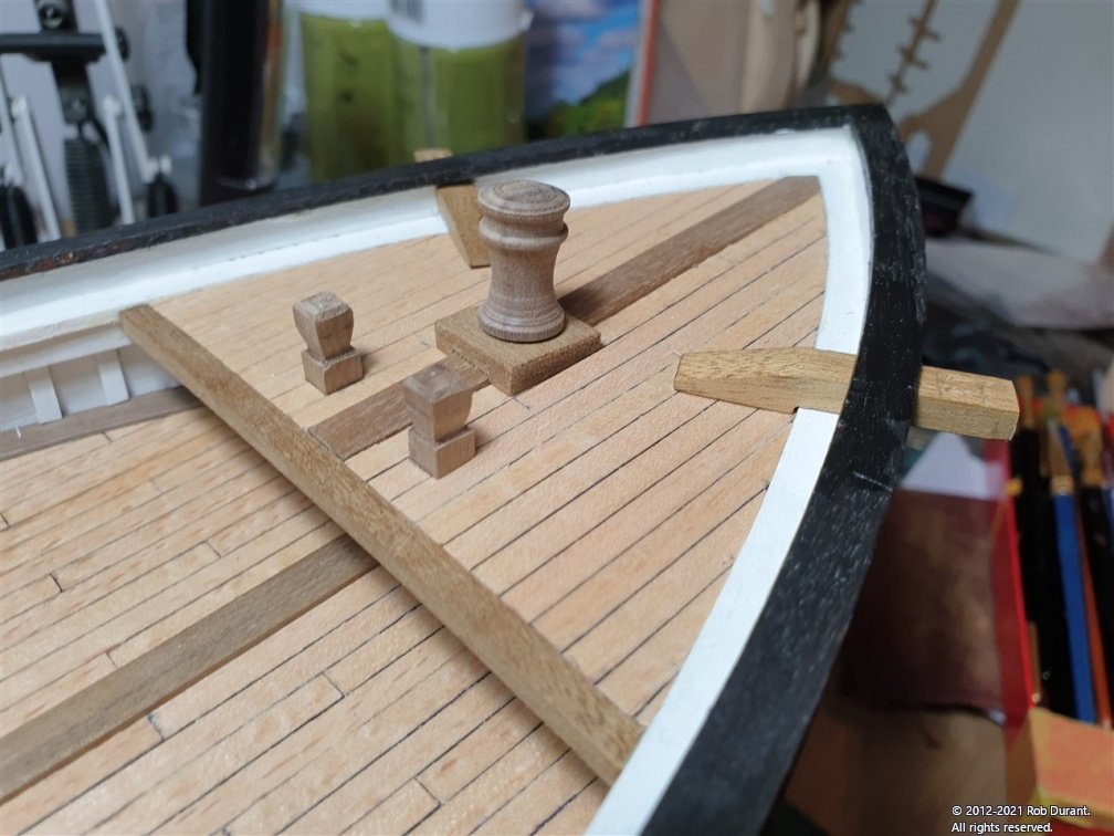
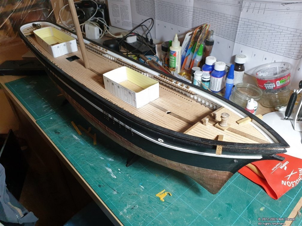
 Hi all, A very quick update... I turned the capstan on the lathe this evening from 12mm walnut. I left a small peg on the bottom to sit in a hole drilled in the platform. The result... And an overview of the deck of Stefano as she stands...
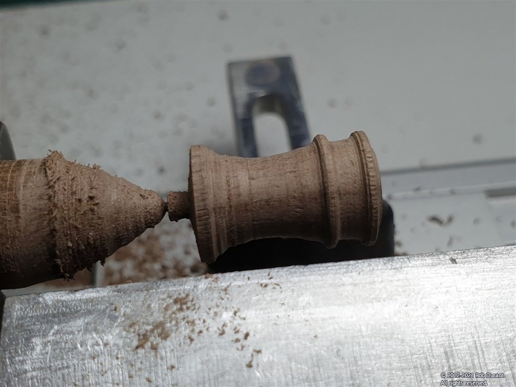
- 286 replies
-
- 11
-

-

-
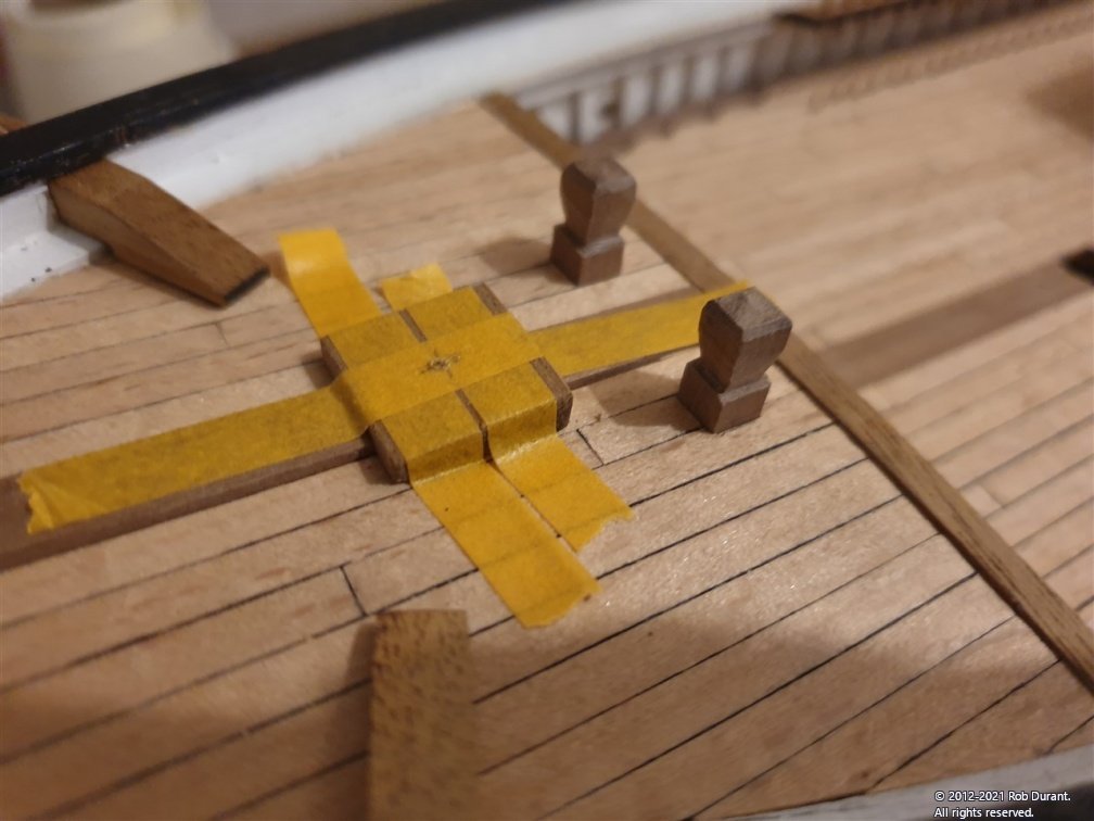
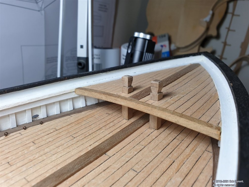
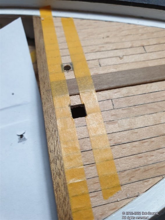
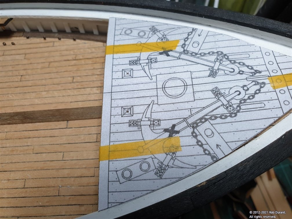
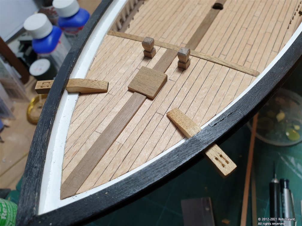
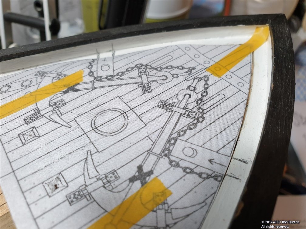
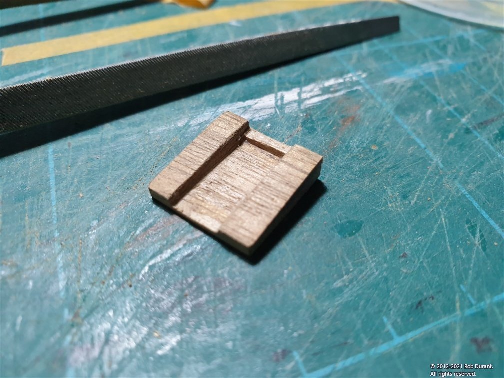
Okay - full disclosure. I've messed up the order of things, and it's entirely my fault and not the kit's! The kit specifically says: Don't stick the fore deck down at this point. It'll make it very hard to install the stays that are mounted beneath this deck. Hmm... somewhere I got over-excited and just went ahead. Anyway, I'm confident I can find other ways to achieve what I need to do when the time comes, but if you're following along and thinking of building this kit, I would STRONGLY recommend that you follow what the kit instructions say, and hold off gluing the fore deck down! Anyway - with that said, I tried removing the deck and it was so well stuck down I was only going to destroy work I was really really pleased with, so we're moving on. The bitts that pass through the foredeck were installed first. These are made out of 5mm square section walnut. I used a printed out scan of the bow area of P9 on plan 1 to make sure these were put in the right place, and the holes were first drilled out, then opened up to fit the bitts with a file. The next step was the anchor davits, which are 6mm laser-cut parts. They pass through the bulwark above the main rail and below the top rail. This again requires careful marking out, drilling and filing, whilst trying to protect the rails. Marking out the positions of the holes... (yes, it looks a lot like the photo above, but if you look closely there are pencil markings where the boat davits go, now... 😆 ) Cutting out the holes... The end result... Finally, I made up the capstan base. This is a 4mm walnut part, which needs to be sanded so that the top surface is horizontal despite the rise of the deck towards the bow. It also needs to have the slot filed into it for the king plank. I over filed this and had to add walnut back in to make it fit nicely. The next step will be to add a variety of turned parts from dowel (the davit bitts, capstan, compass and an attempt at the balustrades for the railings. I have a small lathe so this should be simple enough, although as I think I've said before I'm a little nervous about trying to consistently turn out the railing uprights. Also, I need to add the metal work for the anchor davits. I've paused because I couldn't decide whether I would leave the davits natural, or paint them. I'm erring towards leaving them natural. The alternative is to paint them white to match the upright between the rails. All thoughts welcome! Take care Rob
-
She's looking very smart. Thanks for posting the progress. That yard looks very neat with its various cross sections (circular and octagonal) along its length.
-
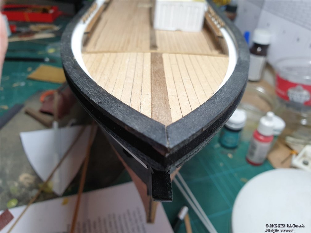
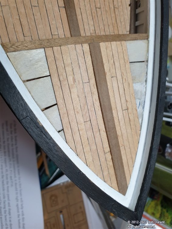
Hi all, The foredeck is in place and planked. I made the planks shorter lengths as per the main deck for the first three rows on each side of the king plank. Beyond that the planks seemed a realistic length to be full runs. And the finished article... The angle of the photo makes it look like the kingplank isn't quite lined up, but in fact it's spot on Happy building Rob
- 286 replies
-
- 11
-
-
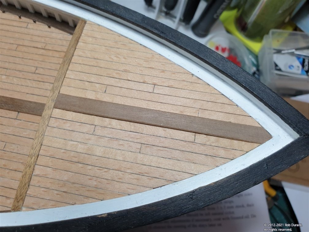
Thanks Bob for your kind words. A little more progress. I added a couple of "shelves" out of 1.5mm square walnut to provide a little more support for the edges of the foredeck aft of the forward bulkhead. Then I checked the plans to make sure there's nothing under the foredeck that needed sorting before I fixed it in place (there wasn't anything I spotted on plan 3.) I glued the king plank onto the foredeck, sanded it so it was thinner and merged more nicely into the rail at the bow and the support at the aft end of the foredeck, and glued the foredeck in place, clamping it to make sure the edges glued down well. And here's a photo of the progress from a few angles... A little touching up of the white rail paint will be required, and then the fore deck will be planked. Happy building, all Rob
-
Hi Jason. It came that way and it really does give plenty of flex to the part to let in bend in two directions.
-
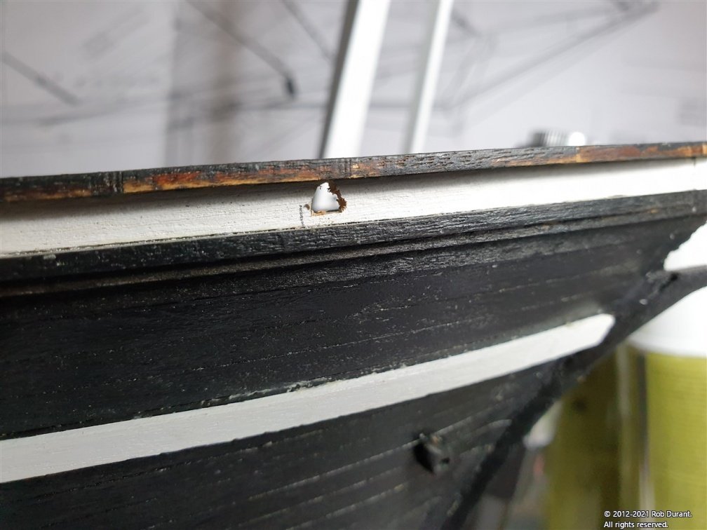
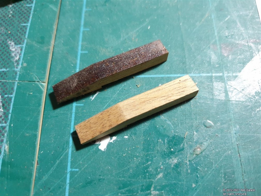
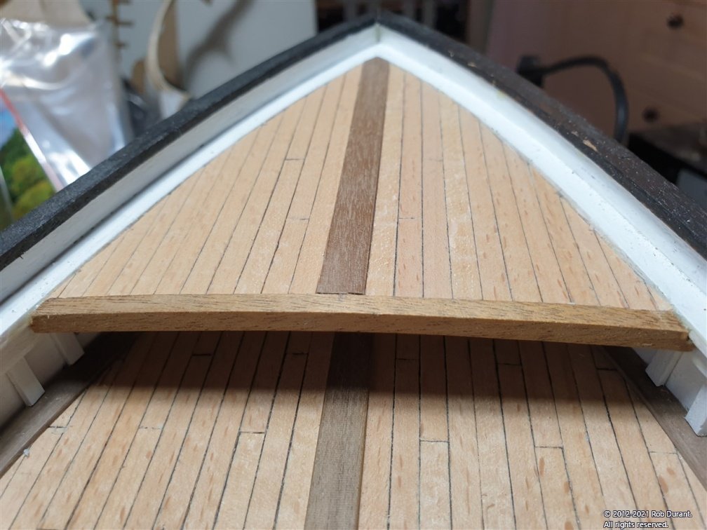
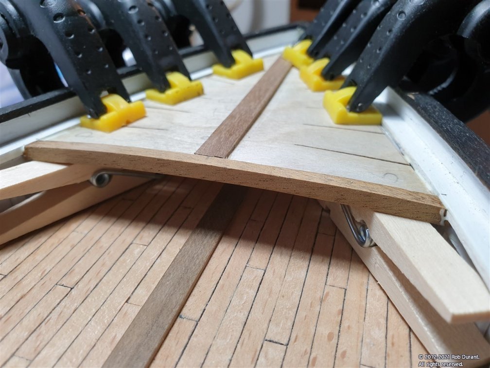
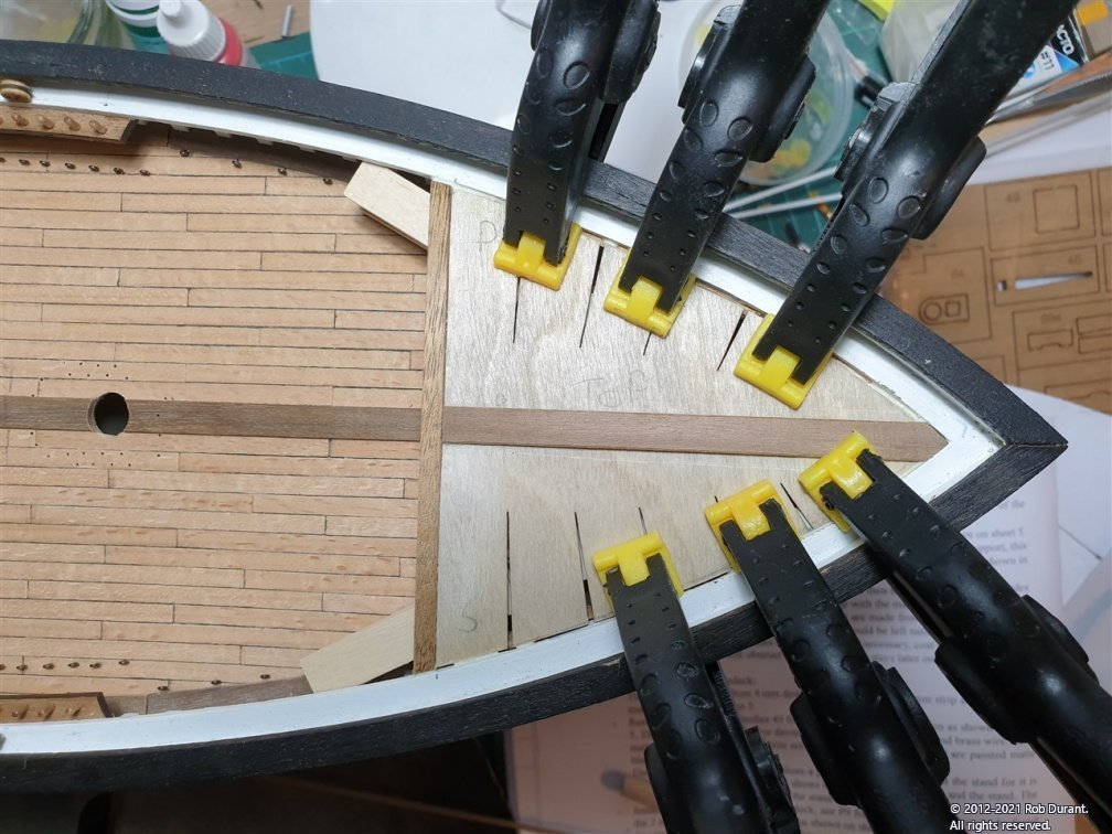
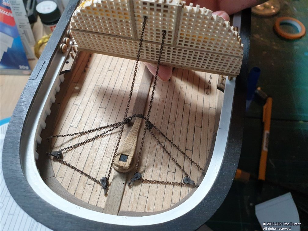
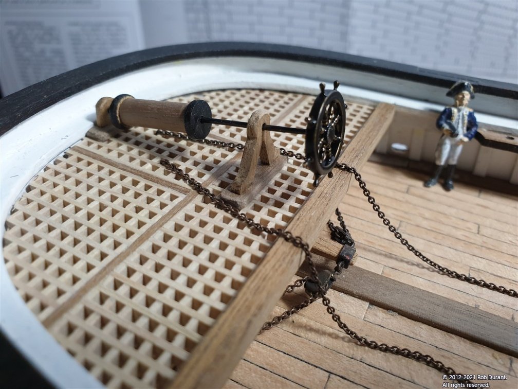
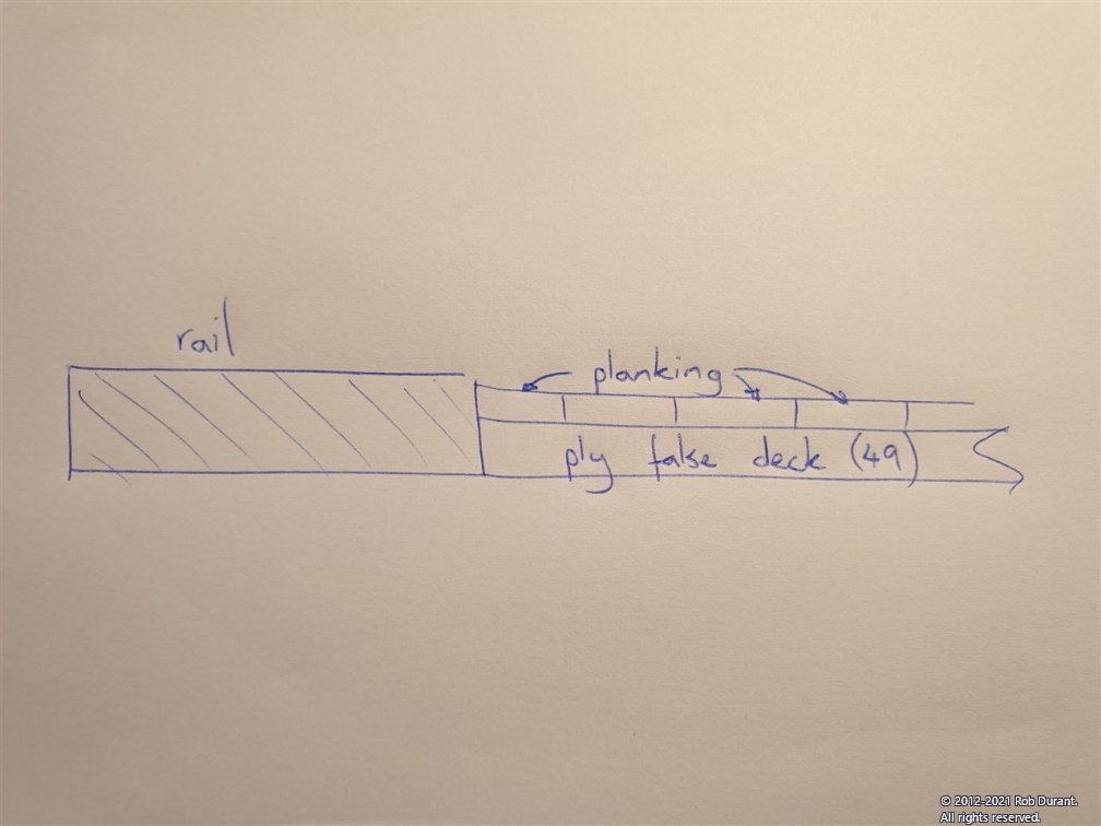
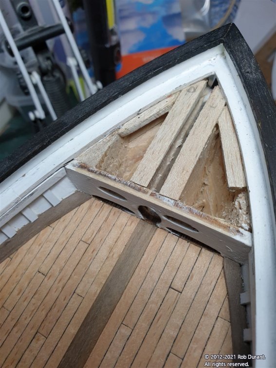
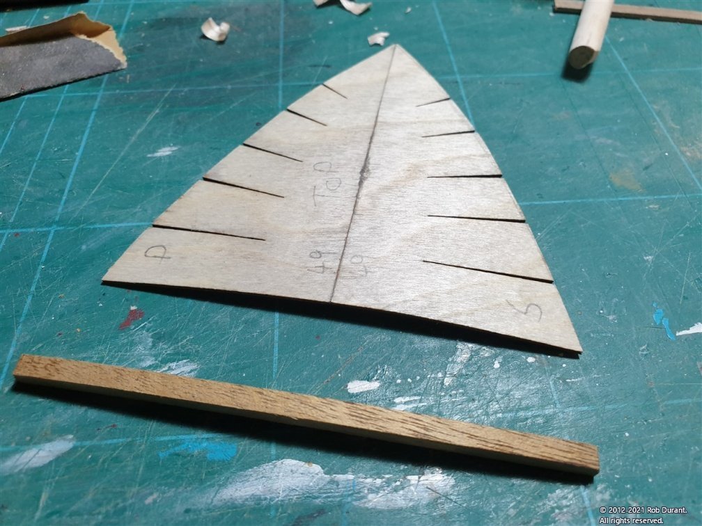
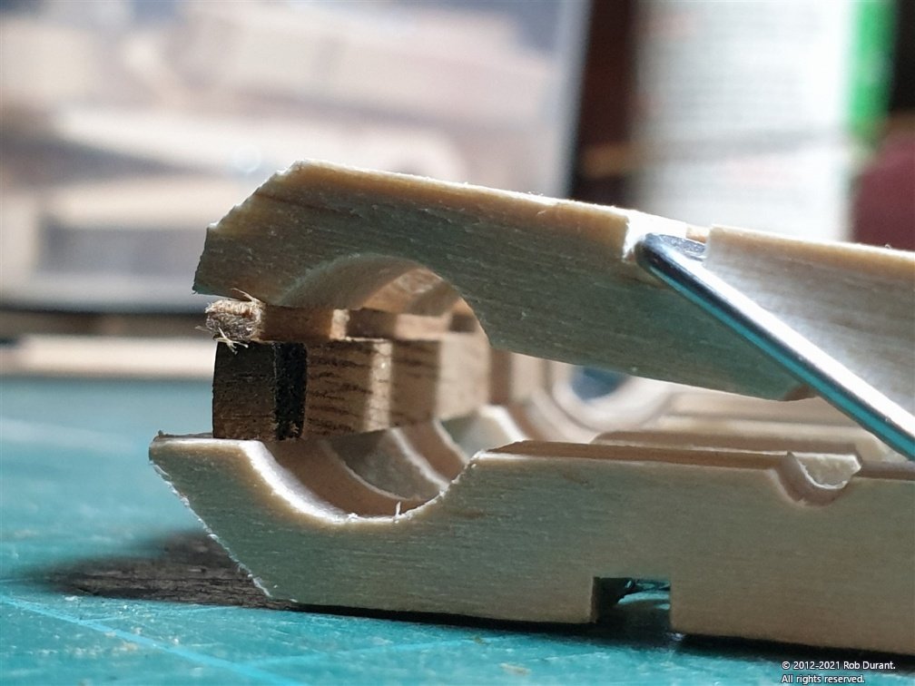
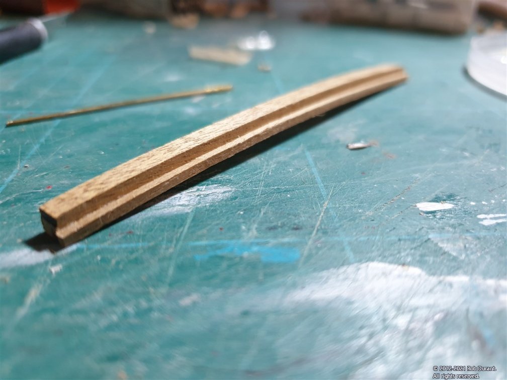
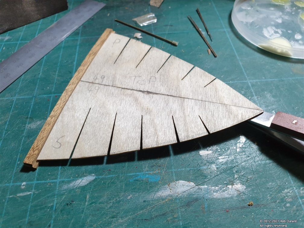
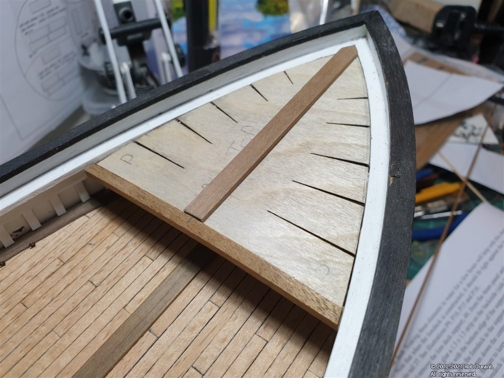
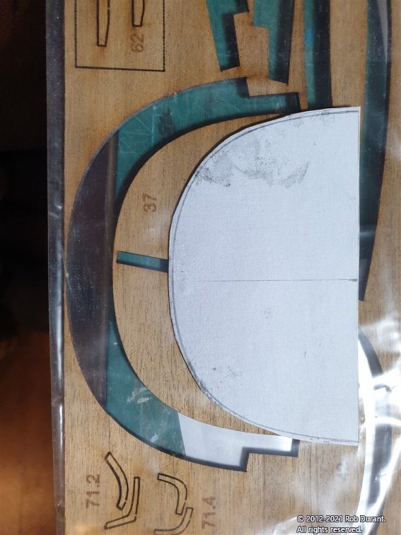
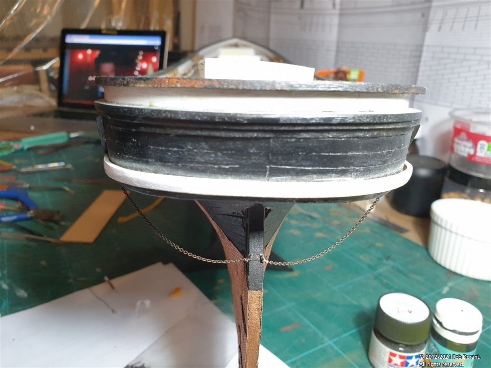
Thank you Keith, and thank you everyone for the likes. A little update on the aft steering platform, and then onto the foredeck. First, I added some small supports to the uprights to make them look a bit more like they belonged. These were made out of 2x4mm walnut, and you can see them in the third and fourth photos below. They're glued in place on the platform, which made assembling everything else considerably easier. Then, having added pins to position the steering platform at the rear, and having painted the steering components, I threaded the chains through the grating, and I've wrapped it round the drum. I'm not sure about the black ship's wheel yet... I'll see if it grows on me. Next I focussed on the fore deck. This is section 49 of the instructions. It composes a ply false foredeck in two halves with cutouts to allow it to flex, and a 4mm walnut beam that supports the aft end of the foredeck. The instructions say that the foredeck will need to be soaked for hours in order to shape it, however the shaping is, in fact quite slight. I stuck the ply foredeck together with superglue, put water on it, and used my violin rib bender at 230 Centigrade to give it some shape. Once the curve was in, it needs to bend upwards. It will glue neatly in place, but needs supports round the edges, otherwise, it won't make a secure base for the planking. I've begun adding those supports using balsa, and so far it's looking okay. I got confused here, initially. The instructions say that the foredeck should meet the bottom edge of the bulwark rail. It wasn't entirely clear what that meant... Here's a picture that hopefully will explain it better than words... Before I worked that out, I thought the ply false deck needed to go under the rail - and spent quite a while getting rid of the balsa support I had in the bow area down to that level. Then I realised how silly that would look, and spent a while putting it back! 🙄 The supports currently look like this. The foredeck, once bent looks like this... It's not a major bend, but getting the bend even across the gap took a bit more patience. Even pressure across the join whilst it was steam bent was important. The 4mm walnut part has a 1.5mm strip glued to it. This was done by gently bending the 1.5mm strip then clamping until the glue set. It was left overlength, then trimmed once the glue was dry. The support is too long to fit - or at least it was on my model - but rather than trim it separate to the ply false deck, I glued them together first. Before I could do that, I had to trim the aft edge of the false deck as it had curved edge. I still haven't worked out why, but there we go. It was carefully trimmed with a steel straight edge and a sharp xacto knife, then glued to the support. Now the task of fitting the support to the model could begin. In honesty, I trimmed it a little short, but nothing major. It just isn't quite as neat a push fit as I like to aim for. I've cut the king plank, but I won't fit that until I've got the false deck firmly in place. Before I do that I need to return to the plans and carefully make sure I'm not losing access to something I need to get to. It would be frustrating and invasive to have to remove this platform to regain access down the line! The instructions do say to fix the platform in place, but I have an irksome memory that I may have neglected to put some eyelets on the deck earlier on in the instructions. Anyway - here is how it looks dry-fitted at present. (nb: the false deck is sitting a bit proud at the bow, but it does sit lower when I push it down. Also, the king plank hasn't been finally shaped yet, and will be sanded thinner to merge with the deck support beam and to be thinner at the bow end.) Happy building to you all. Hope this helps someone following on. Rob
- 286 replies
-
- 11
-
-
You're most welcome Glad it's proving helpful.
-
You've done a beautiful job with that deck planking Jason. Really glad to hear none of your models suffered with the water ingress.
-
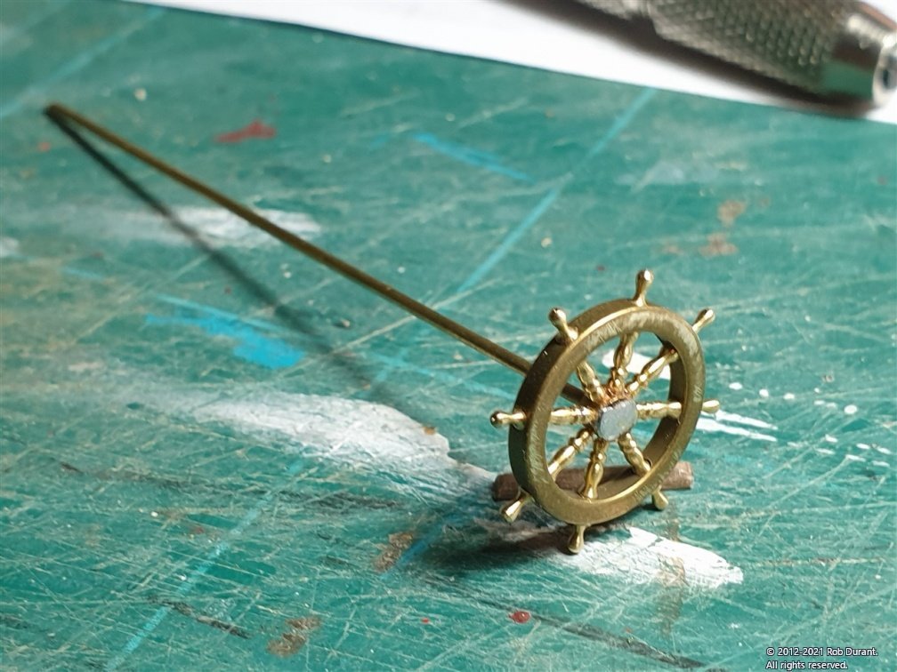
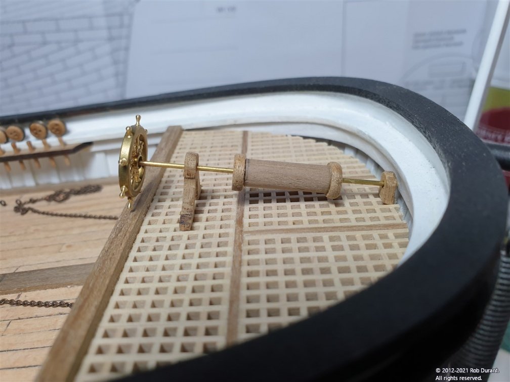
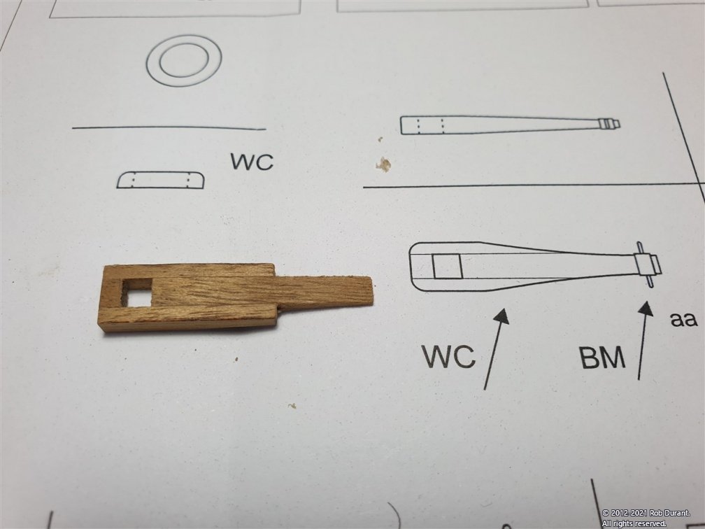
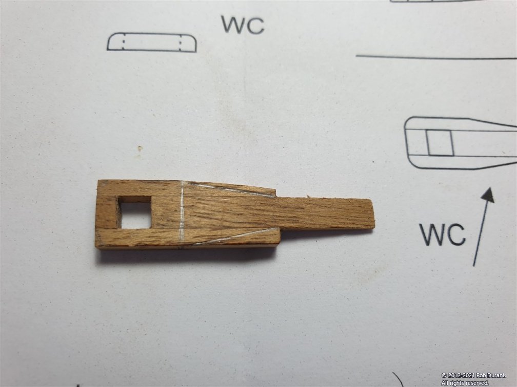
The next task was to take a look at the ship's wheel arrangement. I had already bought a replacement 18mm wheel, which was the perfect size. However, it needs a long rod coming out of the back, and the one provided is 1cm or so. Initially I thought I might simply solder a longer length onto it, but it is vulnerable, simply sticking out, and the joint was hopeless. Instead, I realised I could simply take the existing rod off, and replace it with a 1mm brass rod cut to the right length, soldered into place. The walnut parts (parts 47, shown on Plan 5 in the kit) were cut out of the walnut sheet. Initially I managed to snap the post that holds the rod up, and wondered whether it would simply disintegrate when cleaning off the laser char, but it actually proved to be more robust than I expected. This section of the build was yet another head scratcher. It shows a 6mm dowel with a hold drilled through the middle. Seemingly simple enough, but I don't possess a large lathe or a pillar drill, and my efforts to drill a 1mm hole through a dowel have been shaky at best! Anyway, eventually I bit the bullet and tried with my proxxon lathe. As predicted the drill wandered, and what was a central hole at the entry point was at least 2mm off by the time it came out the other end of the 16mm long dowel. Undeterred I enlarged the hole so that the 1mm rod could pass through straight, and used the end parts provided (which were turned in my drill to remove the char) to line up the rod when glued on. All in all, it was alright, but it's all left to the build to work out. It looks okay - as shown dry-fitted below, but I think I may try and tidy these bits up a bit and make them look a little smarter before they're glued in place. I think I may also add some planks to show where the parts are mounted on the grating before fitting them finally... they look a bit flimsy just placed on the grating. All comments and thoughts welcome! That's it for this evening. Happy building, all, and a happy new year if I don't catch you before then! Rob
-
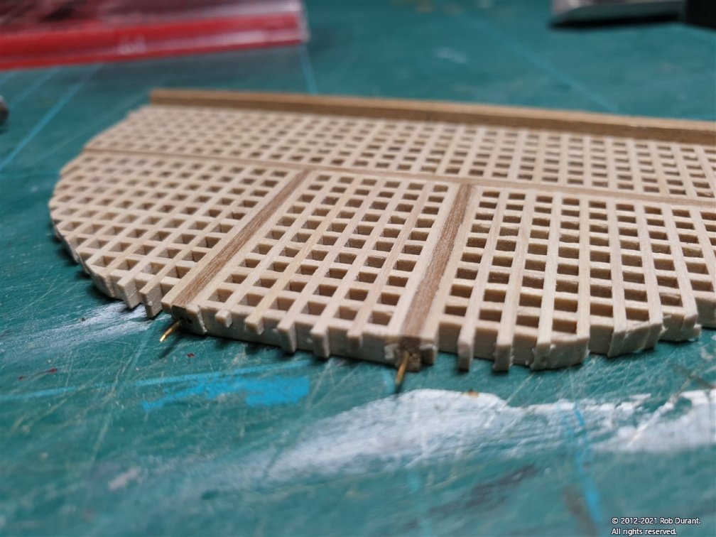
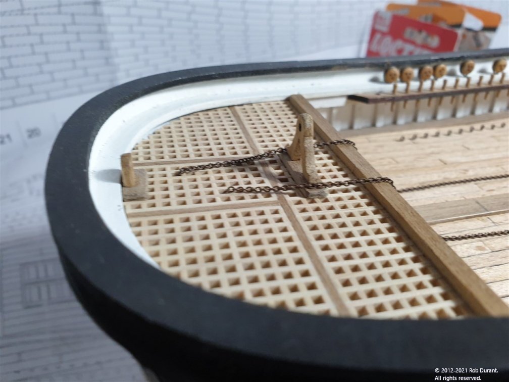
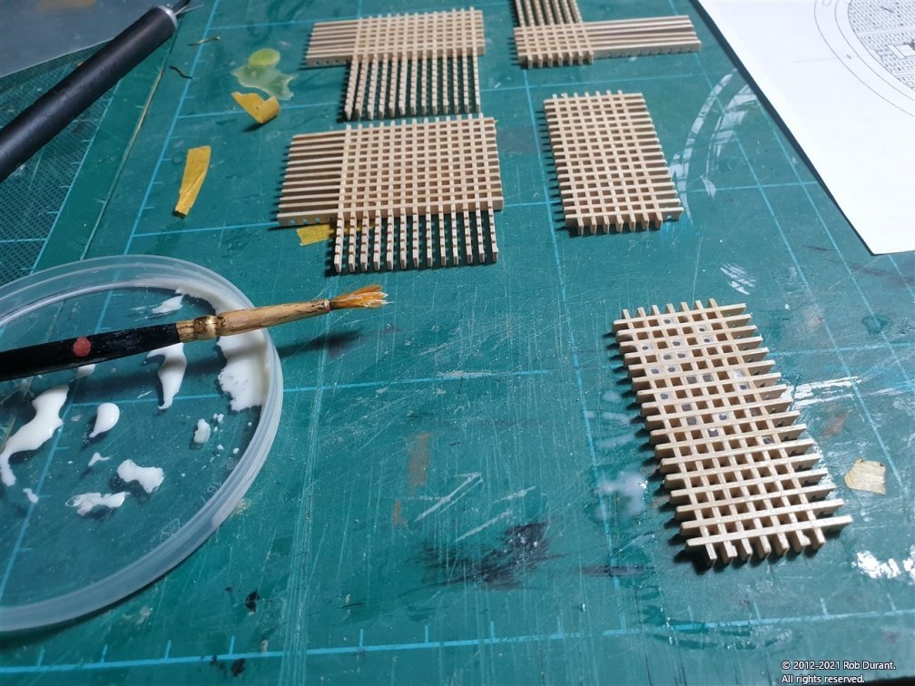
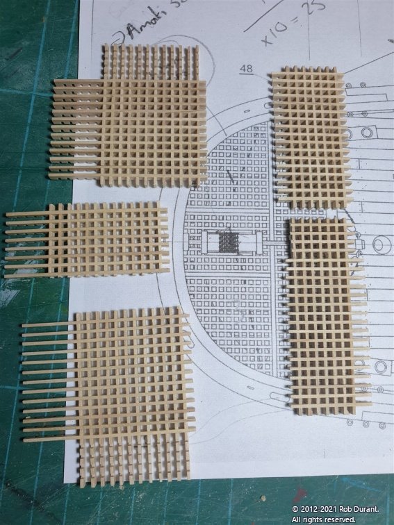
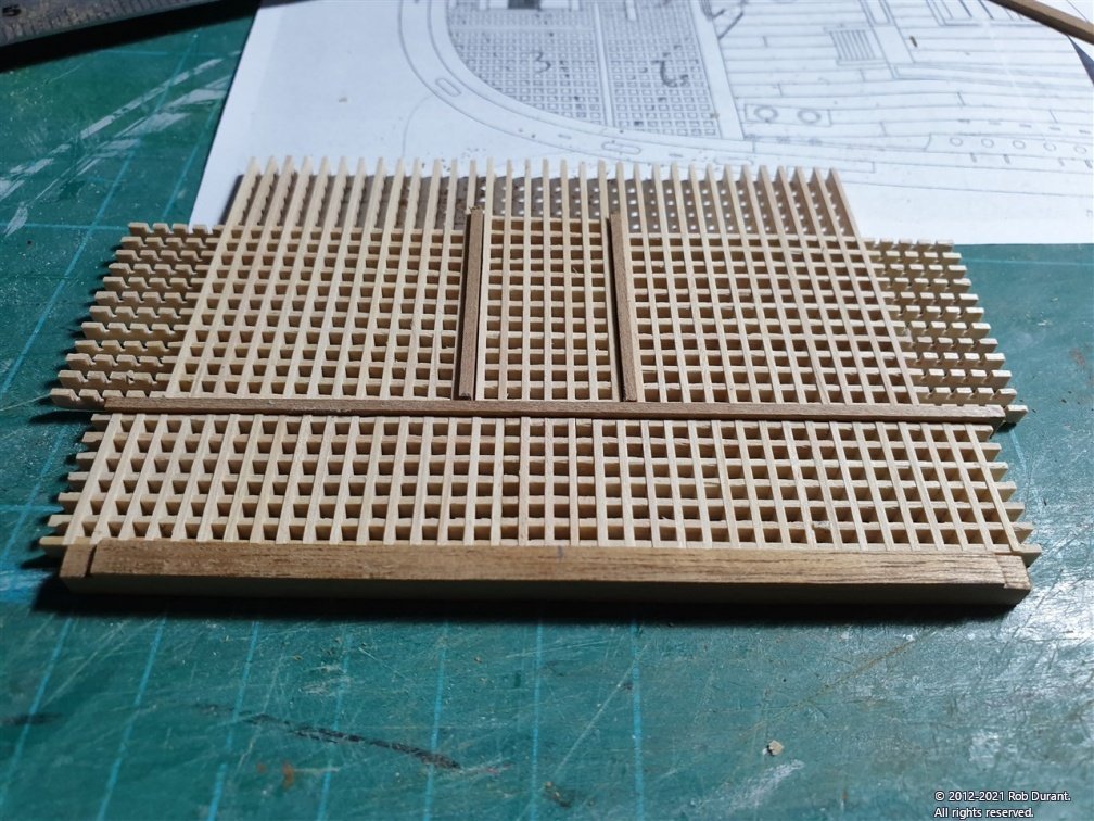
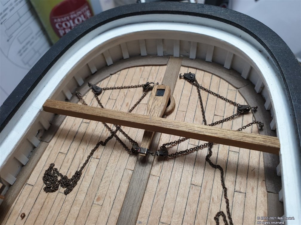
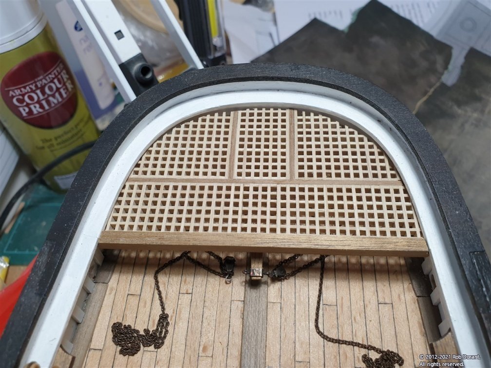
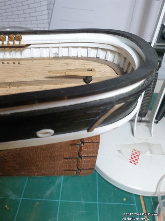
Thank you all for the likes. Hope you've had a great Christmas! I've been working on the gratings at the stern for Stefano. These are made from grating strips provided in the kit, which are put together loose, then brushed over with diluted carpenter's glue (Aliphatic resin / yellow glue is a souped up version of PVA glue). The sections of gratings (as shown in P9, P10 on the plans) are too large to be accommodated by one length of grating strips, so these must be carefully cut and joined together. I worked out a scheme as shown below... The sections were outlined with 4x2mm walnut, giving an outline as follows. This assembly is upside down (i.e. the solid lines in the gratings will face fore and aft on the up-side, as per gratings on an 18th C ship.) Assembling it this way also means that the flat side is up, although I later sanded these walnut strips flush on the under side as well. This is dry fitted... DON'T glue part 48 (at the front on the picture below) on yet... it will be glued so that it's flush with the bottom of the gratings, not the top, as the top of the grating will end up level with the bottom of the rail, and part 48 will be level with the TOP of the rail. The beam at the front is a 4mm walnut laser cut kit part no. 48, which has been carefully fitted to sit underneath the main bulwark rail so that the top is flush with the rail. This involved enlarging the notches, and setting the width. The assembled gratings sit in the area to the stern of part 48 (in the photo above) and cover over the tiller and chain arrangement. As far as I can tell they will sit just under the bulwark rail so that it looks tidy (there's no way you could get the gratings to look tidy if they butted up against this rail without a lot of extra work to create some walnut trim that fitted this shape, so this is the trade-off! To trim the parts, I made a template out of card using shape left in the laser cut sheet from the main rail part as the template. (nb: it's the lower rail, not the upper!) Then it was a task of gently cutting out the gratings to shape... tedious and easy to break them, but I got there eventually. Lots of test-fitting was called for. Here it is dry-fitted. I won't stick it in yet. Not least, because as I put this together, I accidentally knocked one of the blocks for the tiller chain below off it's hook, and had I glued this platform in place, I wouldn't have had any access to fix it... so I want to make that a little more idiot-proof before I lose access permanently! In fact, you can see it in the photo below. Right - there's more, but I'll put that in a second post.
-
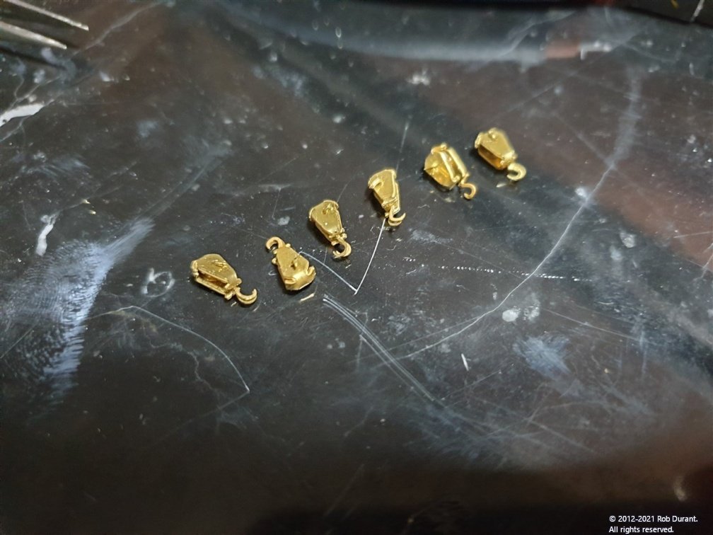
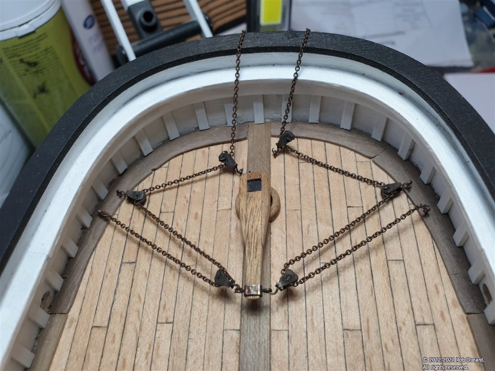
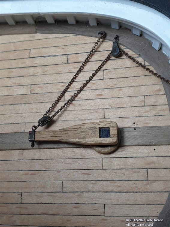
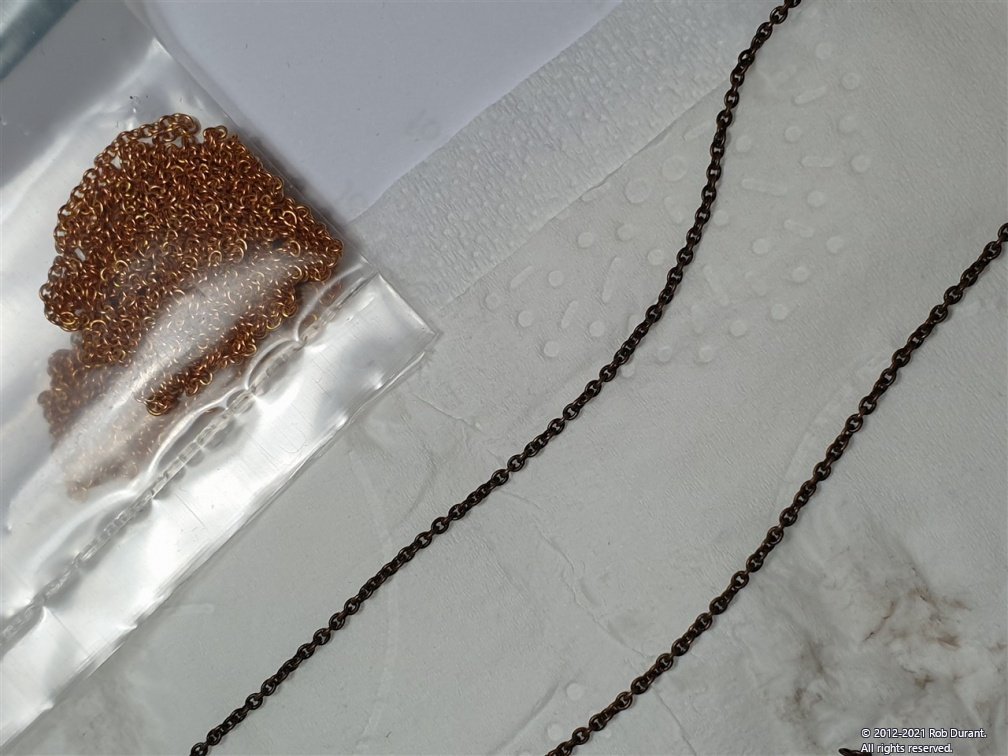
Thank you Jason. Yes, I think it's a mix of instructions that are often quite succinct, and a large quantity of plans that I'm only now beginning to really get my head around, and some simplified items. For example the posts for the balustrade round the rear superstructure are entirely missing from the fittings. They'd be something of a pickle to turn on a small lathe so that they each looked the same. Anyway - that's a challenge for another day. Here is a little more progress on the chain arrangement for the steering. The blocks were completed and blackened, then the 1mm blackened chain (the same chain that's used for the rudder chains underneath the transom) was linked to the first blackened eyelet, and threaded through the blocks for each side. The plans provide good detail for this arrangement. The sides are done individually, because the chain will need to pass through the grating that will go above this setup, and then round the drum behind the ship's wheel. The instructions helpfully remind you to leave some slack for just that purpose. I erred on the side of caution to make sure I wasn't under when the time came to link it all up. Some pictures of my progress... For a first attempt at these photoetch blocks I'm quite pleased, I have to say. They are fiddly and time-consuming, but it's nice to have metal pulley blocks where they would have been metal on the ship. Thanks for all the likes, and apologies that progress is slow, but real life rightly takes priority, and the Barque is, thankfully, patient If I don't post again before then, every blessing to you all this Christmas! Rob
-
You're a braver man than I, David. Those scuppers look like you've got their position perfectly. Did you drill straight through from the outside? Glad to hear you managed to find the solution for the level of the wales and how it all fits together at the prow, too! She's looking very smart indeed.
- 310 replies
-
- 4
-
-
- Diana
- Caldercraft
- (and 1 more)
-
Absolutely stunning - really fascinating to see the two side by side.
- 1,090 replies
-
- 5
-
-

-
- showcase models
- vendetta
- (and 2 more)
-
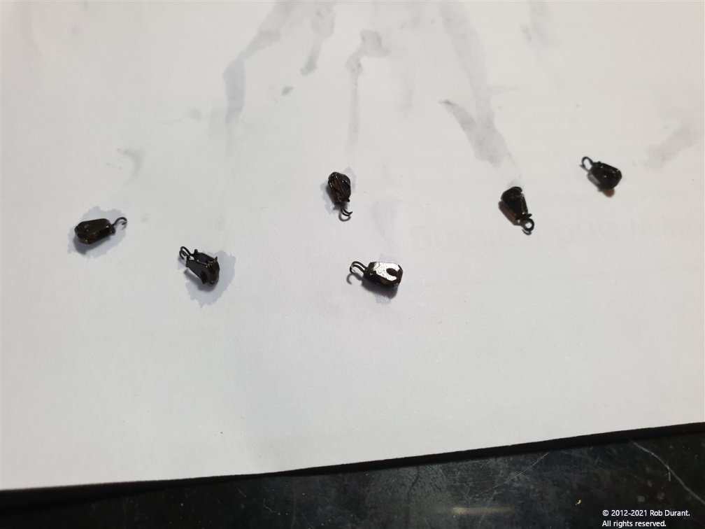
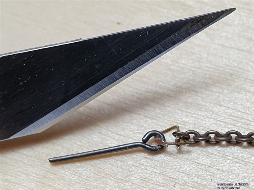
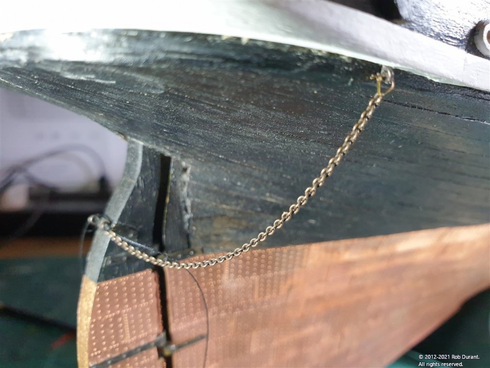
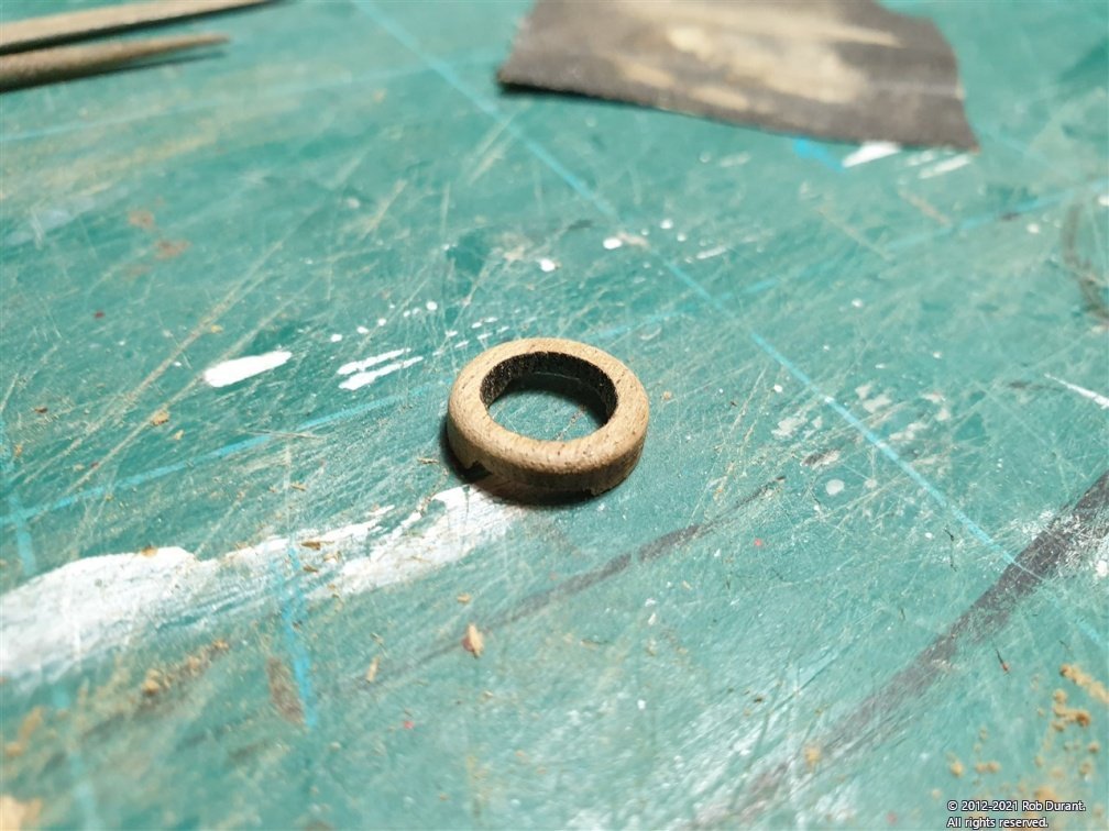
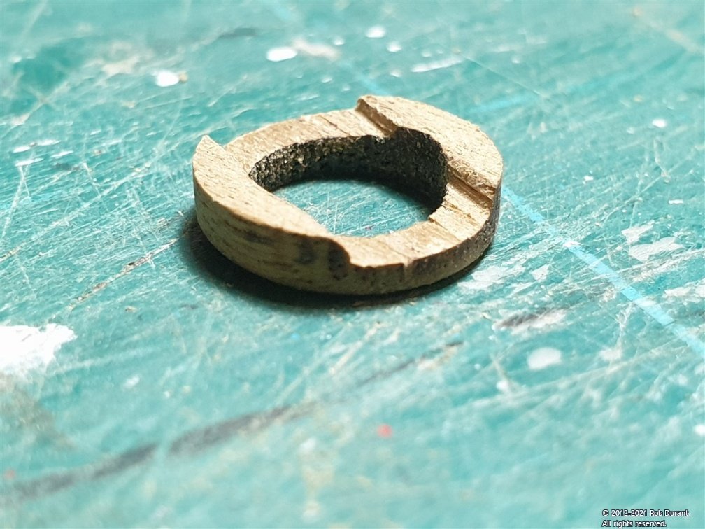
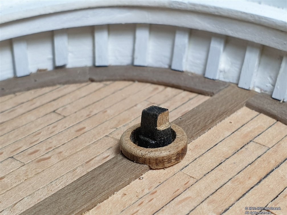
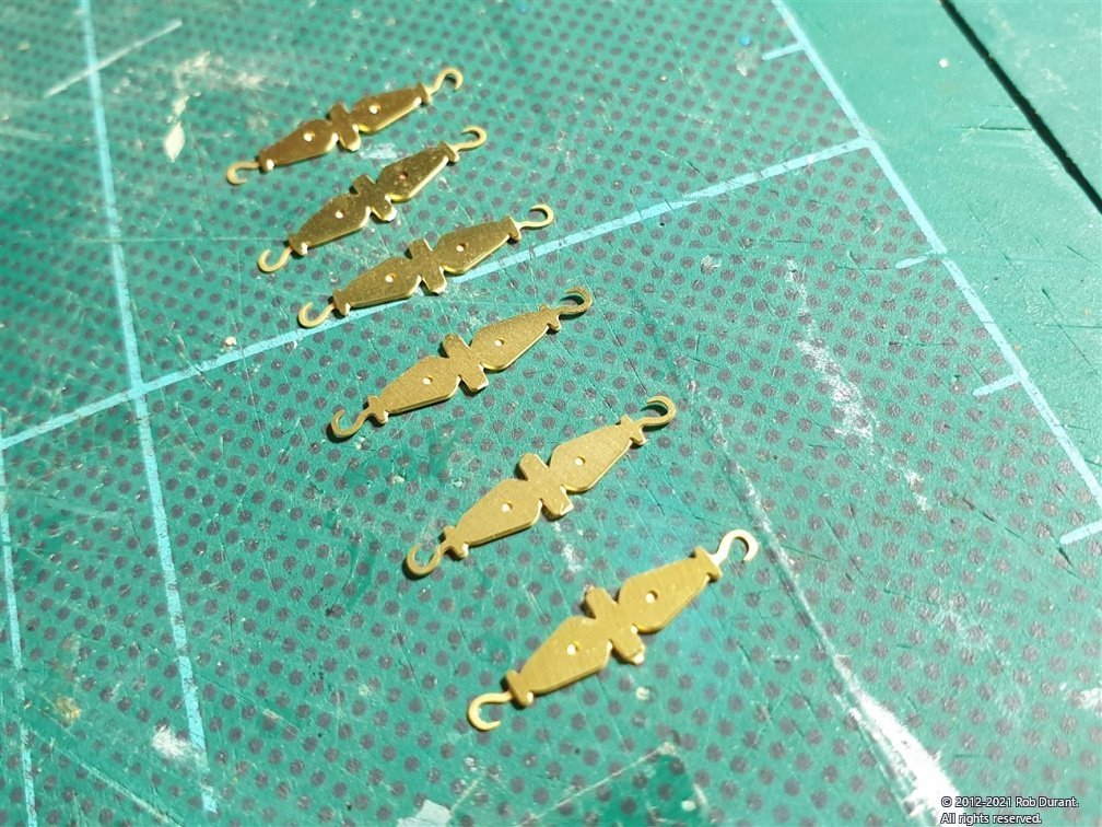
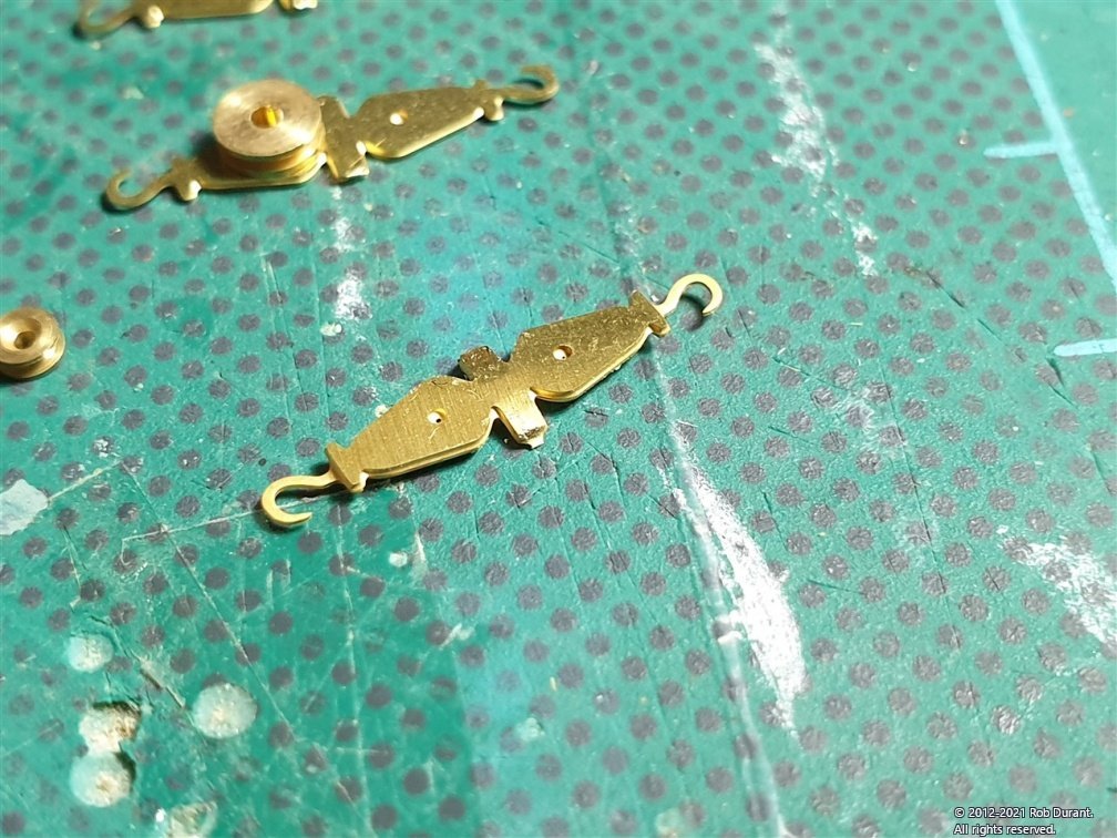
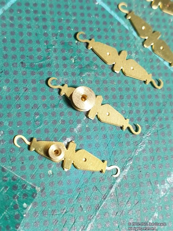
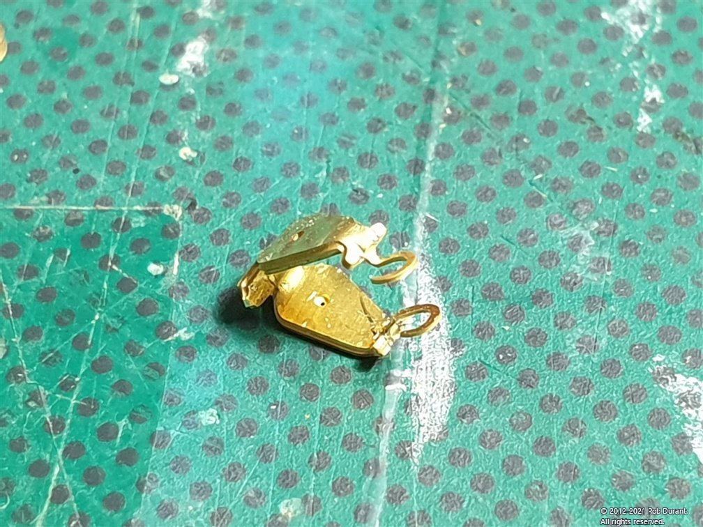
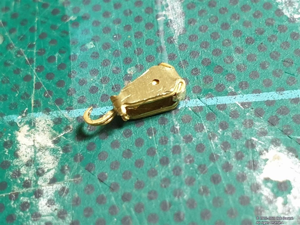
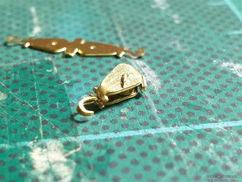
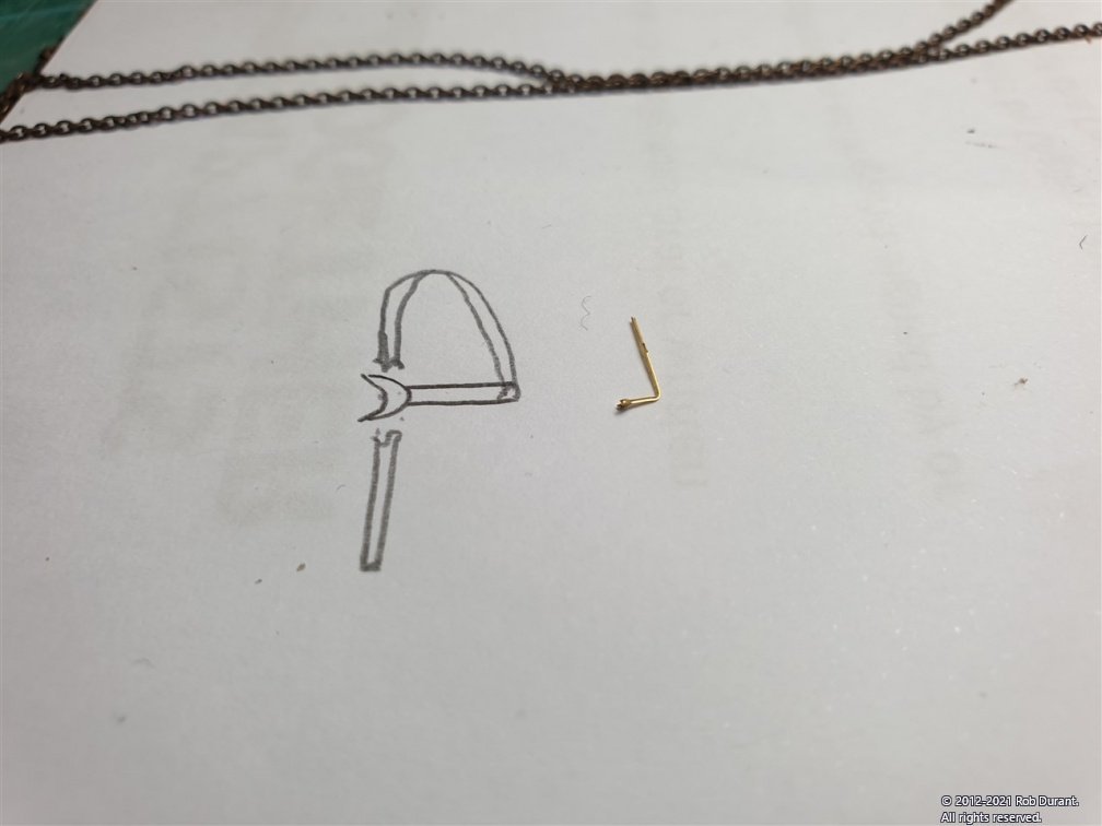
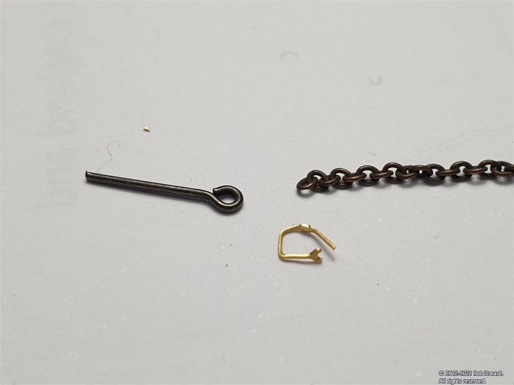
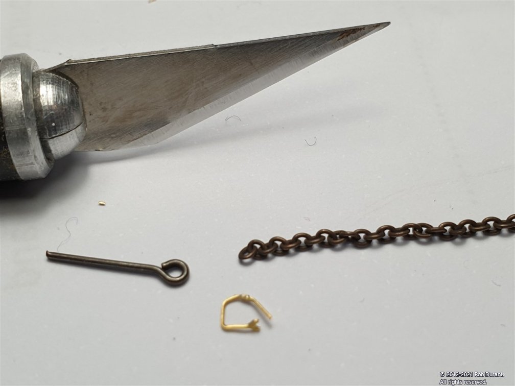
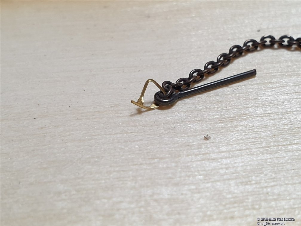
I've done a little work to add the rudder retaining chains, and the rosette round the rudder post on the deck. Rudder chains: Here is the soldered clasp at the end of the chain that will go into the hull against an X-acto #11 blade... The chain was cut to length (using eyeball 1.0), and allowing for a little droop, and tied off to the spectacle plate... The end result was as shown below... Rosette round rudder plate: (part 46 on the 3mm walnut sheet, as I remember). This is a very square part, due to the laser cutting, and I wanted to round it off to make it look a bit smarter... This was done by putting the part onto the end of a dowel that fitted the internal diameter... (masking tape was used to take up a bit of slack). By mounting the dowel in a electric drill / screwdriver, I was able to sand the edges to remove char, and begin round off the top. Once done, the slot was filed into the bottom to accomodate the king plank on the deck. Dry-fitted... Once I was satisfied, it was glued in place. Photo-etch pulleys for steering chains: These are small, but it IS possible They start off looking like this... The bit that will make up the plate opposite the hook can be bent a little first... MarisStella provide the pulley inserts... there are small and large, and no indication in the instructions which is the right choice. Trying them it seemed to me that the large was too big to fit, so I went with the smaller. The bending process continues by bringing the two sides in... Closing the two sides in... Now the holes can be drilled out (0.5mm) and 0.4mm wire used to capture the pulley inside the casing. The bar through the centre holds the unit together, and because no solder or glue has been used up to this point, this whole unit can now be blackened. Rob
-
This is a shame given that this kit seems to be the flagship model for CAF, and the stand part of how the model is displayed when finished ... Hopefully @cafmodel will pick up on this and fix it for future releases It looks good and sturdy, though. It's fascinating watching you work out all the steps required to construct this complex and large model. Thanks for sharing your progress with us all.
-
It's an excellent suggestion and may save me a great deal of faff in the long run and make for a neater end result. I was keen to try out the method suggested in the kit to see how doable it was, but it may well be a step too far for me at 1:63 scale.
-
Hi David. She's looking fantastic! I didn't register I'd changed the gaps with the channels - perhaps because I'd reworked the quarter deck for the lower bulwarks... but it looks like you've worked out a great solution, and I'm sure the captain will be much happier with the shot passing well clear of the shrouds. Looking back on my build, this is one of the few things I would definitely have done differently. Trying to glue in a bunch of blocks to fill the gaps where the chain plates went through was fiddly and annoying, and I should have followed Jason's @Beef Wellington example in retrospect. I would strongly advise having a strip along the outside of the grooves that the chain plates fit into if you can. Here's the post where Jason talks about what he did... Rob
- 310 replies
-
- 3
-
-
- Diana
- Caldercraft
- (and 1 more)
-
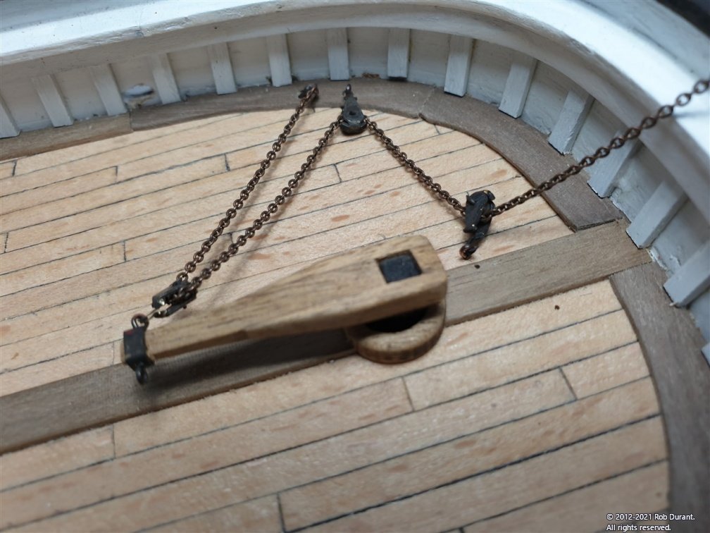
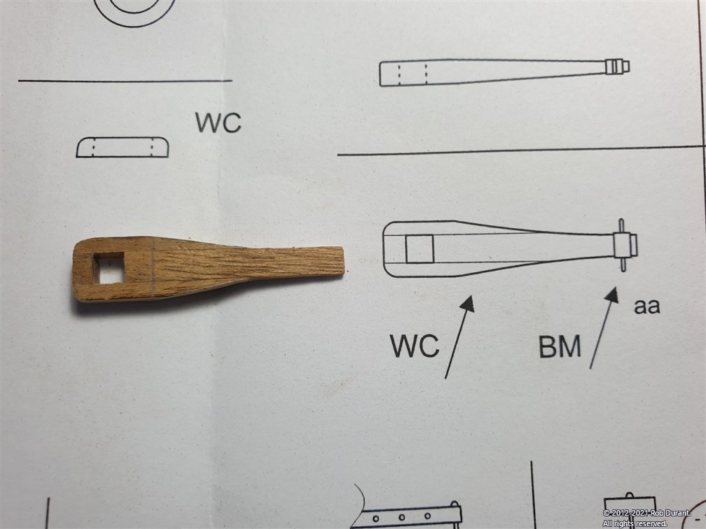
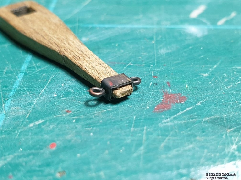
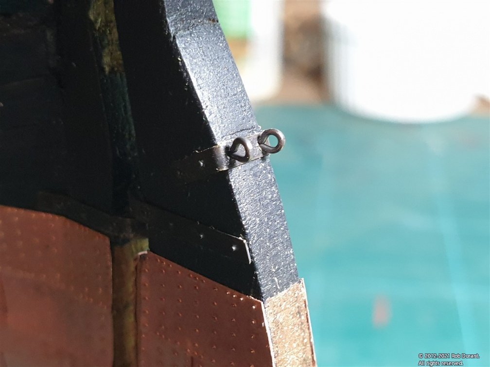
Hi all, and thank you for the likes, I've made up the tiller. This is made up of six parts. Three wooden, and three metal. First is to find the tiller parts - marked as 46 - on the laser-cut sheets. One part is on a4mm sheet, and the other two on the 2mm sheet, but all are very well marked. These are glued together as shown, leaving a gap for the rudder post. The parts glue like this... And can then be marked up for the front to back taper.. And the extra cut back... A test fit meant cutting down the rudder post to size (approx 3.8mm square). Now the photo-etch detailing can be added to the tiller, along with two eyelets (I reused some eyelets I had left over from a previous model, because they were already blackened, and readily available, but there are eyelets provided on the photo-etch sheet. What I couldn't tell was whether there were any assigned for this particular task - there didn't seem to be any specifically marked 46 (for this stage). Here it is with the photo-etch in place... This is _very_ zoomed in - it looks much more tidy to my eye in person, if a little heavy for scale? The part is etched to help with the bending, but this means it is full depth, rather than the half depth of the pintles and gudgeons (which were etched back to give the rivet detail). I'll see if I can live with it, and if it starts to irk me, I'll replace it with card, painted with Tamiya dark iron... instead. I've also put the eyelets onto the spectacle plate ready for the rudder chains... And blackened one of the 1mm chains (3x 1m lengths are provided in the kit) ready to install. And I've started working out how to form the shackles - the smaller of the two sizes provided - which are tiny, indeed. I found cutting the excess brass away from these parts quite tricky, and you can see the remaining on the part below. Filing it is, from what I could tell, almost impossible as they are so delicate. Perhaps I could use a sharp knife and a solid surface instead. More practice is required, evidently! The following photo gives some idea of the size... Linked together, and awaiting solder, it looks something like this... I've yet to see if I can solder this... it may pleasantly surprise me, but I ran out of time today More soon! In the meantime, happy building to you all. Rob
-
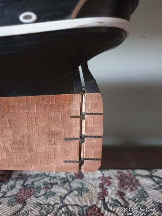
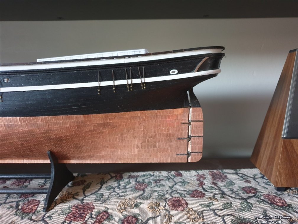
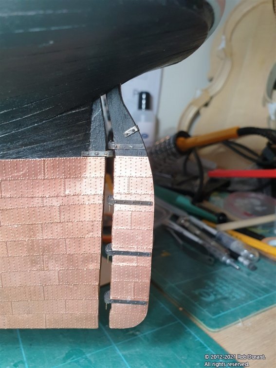
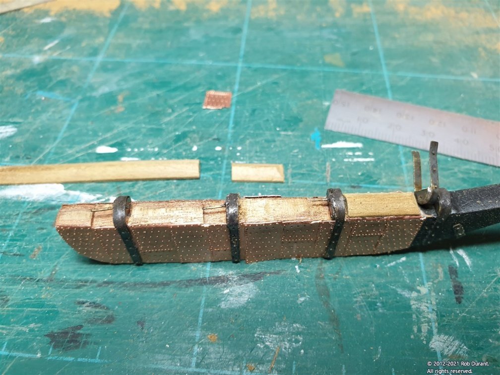
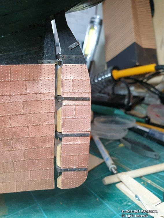
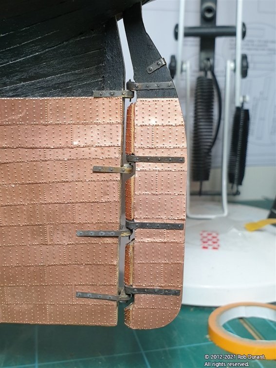
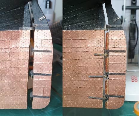
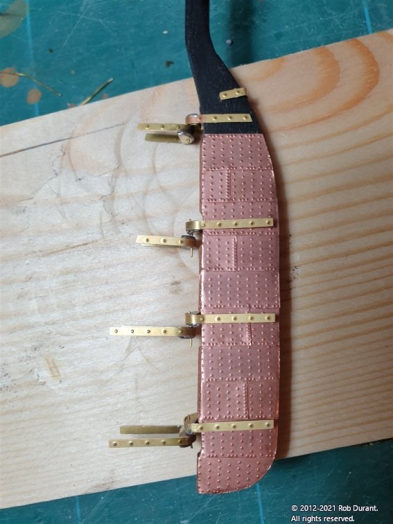
Okay - more work on hanging the rudder... I test fitted the rudder with the pintles and gudgeons in place, and it quickly became apparent that there was going to be a massive gap between the rudder and the hull. I wasn't happy with that gap at all... but equally I didn't really want to start over, and I wanted to try and use the photo-etch pintles and gudgeons if I could, because they're really nice and sturdy. I put my thinking cap on, and it occurred to me that a big part of the problem was that the rudder didn't extend very far out towards the forward extend of the pintles... so I decided to increase the size of the angled section at the front of the rudder. I used the walnut from the laser-etched sheet that I took the rudder from, and created a triangular cross-section that I could then use in between the pintles. In the photo below I've only fitted the top section. The remaining section is behind the rudder with the next part already cut and bevelled at the top. The net result is shown below... Then I covered the extra sections with copper tiles. Having taken this photo, I then opened out the hole in the hull that the rudder passes through to allow the bottom of the rudder to swing forward a little more. Here's the before and after (still dry-fitted)... It's not perfect, but I'm much happier with the gap. There's a bit of touching up to do and it all needs to be fixed in place, but if I were starting out all over again, I'd definitely do a lot more to the shape of the rudder first of all to make sure I avoided this re-working. That's it for this evening. Thanks for the likes, and happy building to you all. Rob
-
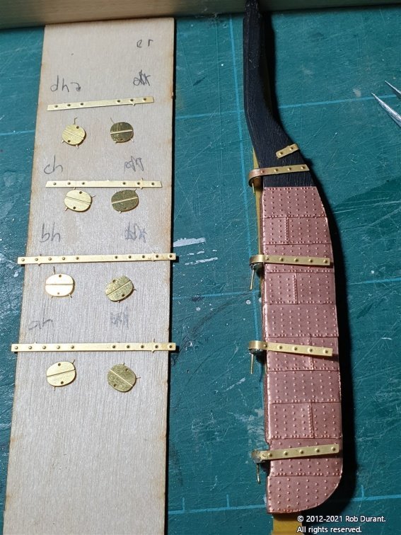
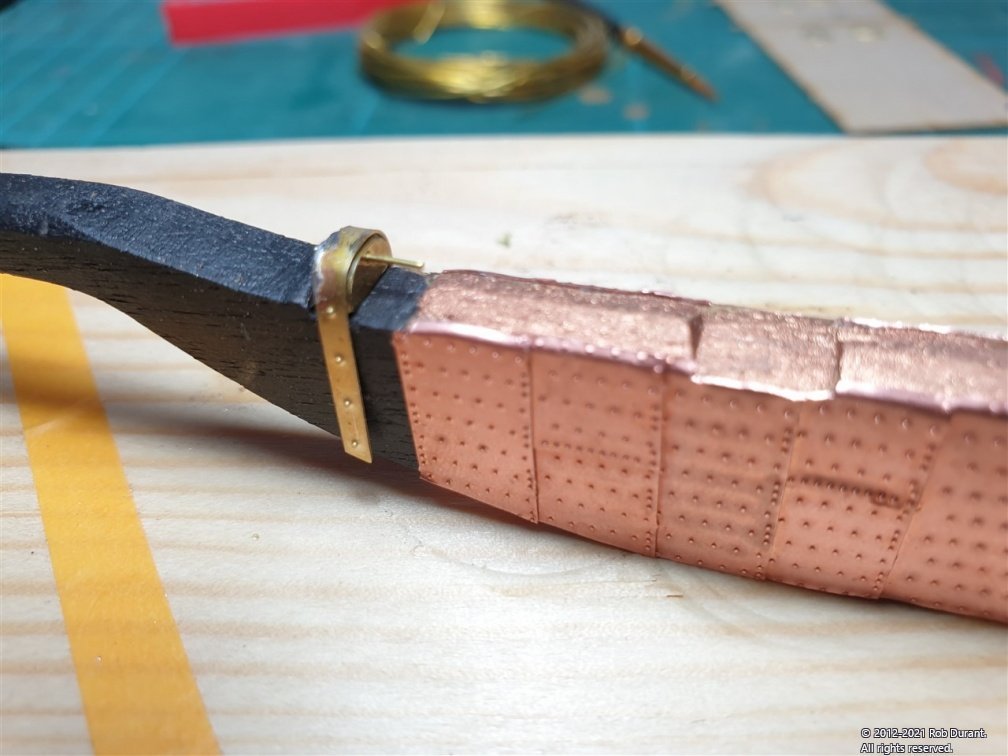
Hi all, Thanks very much for the likes. A little more progress to report. I've completed soldering the pintles and gudgeons. The process for the gudgeons is the same as that of the pintles, except when you have lined up the formers using the wire through the hole, don't solder the wire into the formers. Instead, use it to keep the formers in place, until you've soldered the strap in place, then simply remove the wire, and it's ready to accept the wire from the pintle. Some pictures of today's soldering... here are the pintles completed. Then I cut out the photo-etch parts for the gudgeons... (Again, it goes ah, bh. ch, dh for the gudgeon parts going up the rudder, to partner with the pintles: ar, br, cr, dr). In the photos below, the pintles are only dry-fitted. I'm planning to blacken these before I fit them, as I'm not a fan of the brass / copper colour clash. I know that iron and copper don't like each other, so I may paint the pintles and gudgeons below the waterline copper... or I may just go with it, because, hey, it's my model, and perhaps someone painted them black 😁😋 More soon. Rob
-
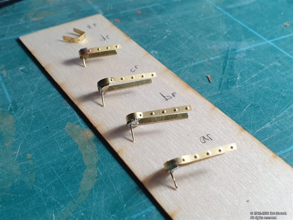
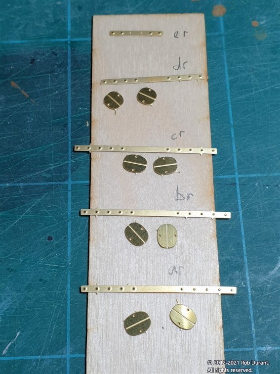
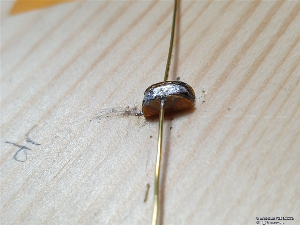
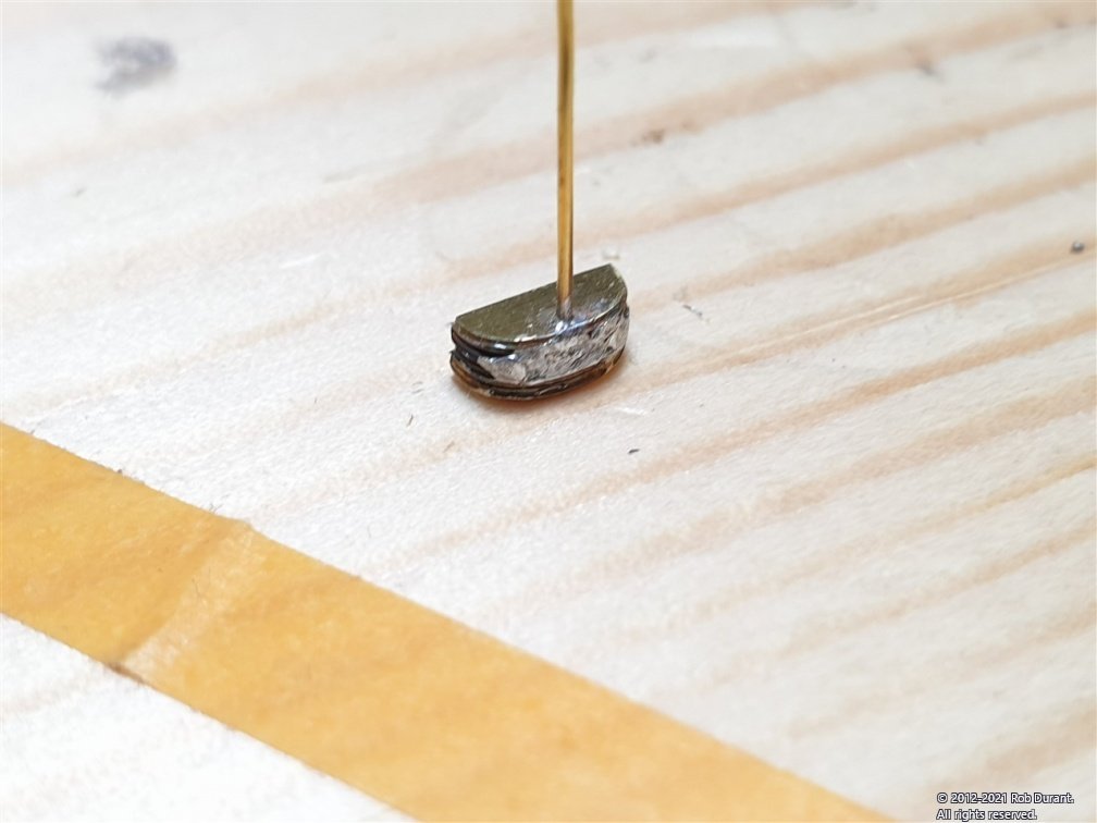
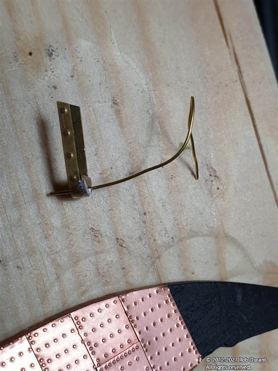
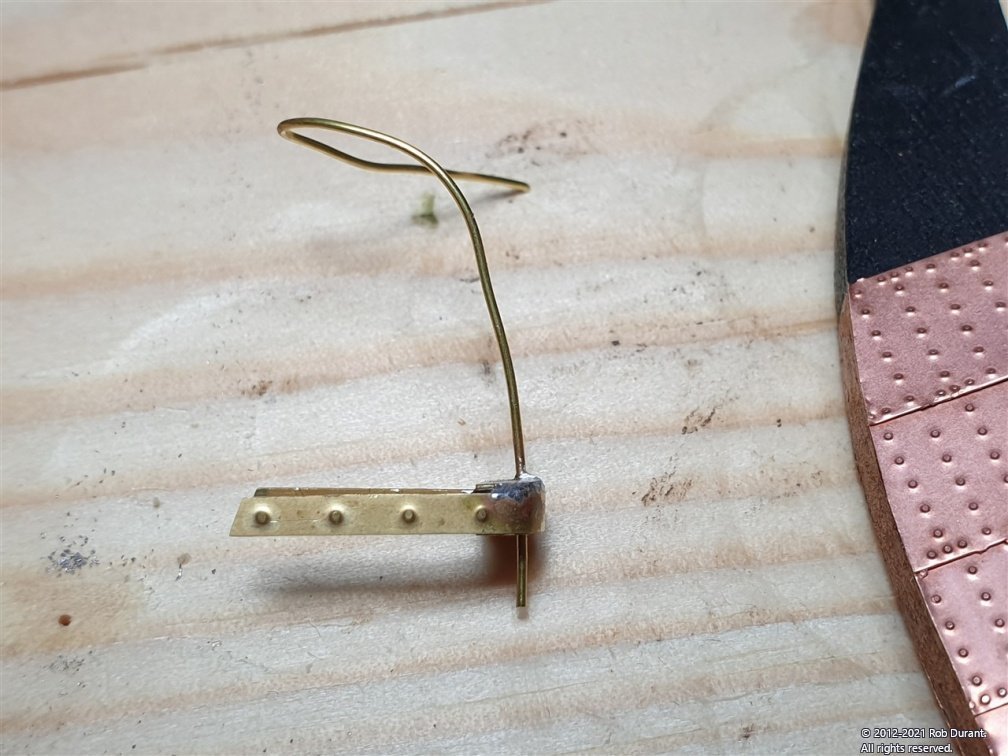
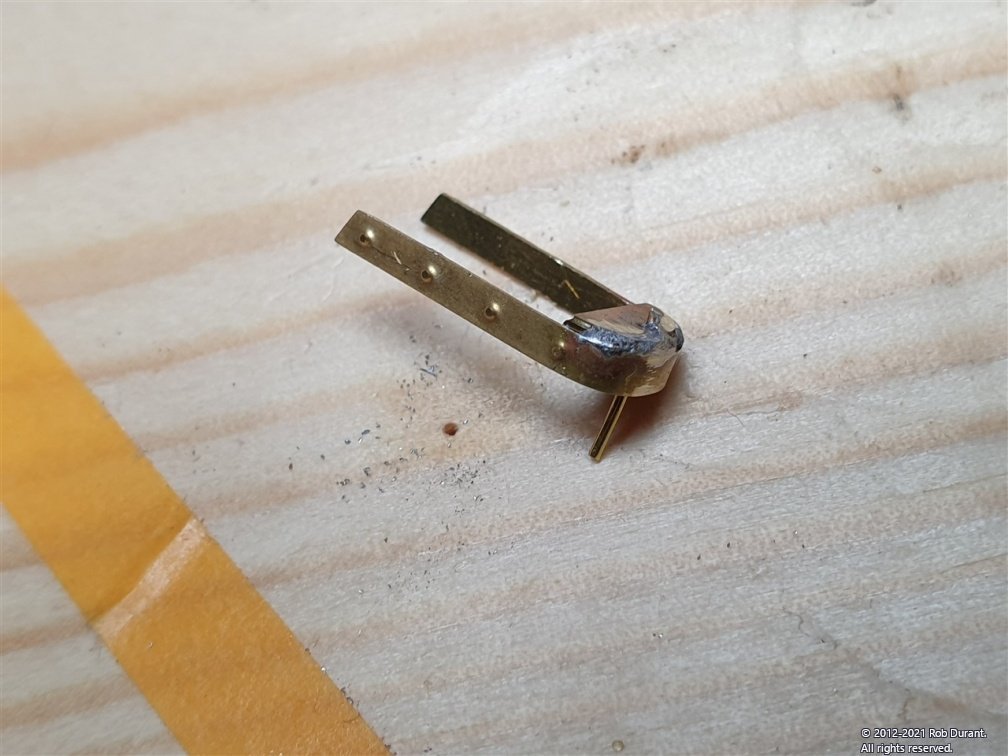
Okay... pintles and gudgeons... MarisStella in their plans have sections where they show all the component parts of one area of the model (e.g. the rudder) laid out alongside each other. In plan 5, section P19, all the component parts of the rudder are shown... At first glance it seems that there's duplication, but actually when you look more closely it's the pintle components and the gudgeon components. (I was struggling to remember which was which, but the pintle is the one with the pin, mounted on the rudder, and the gudgeon, the one with the hole mounted to the hull). These components are all labelled neatly on the plans, and those labels are also on the photo-etch fret, so no problems identifying them. They go as follows: er is the strap at the top of the rudder (the spectacle plate that provides the mountings for the rudder chains) This will have two eyelets added. dr, cr, br, ar are the straps, with two associated pieces of photoetch that form the pintles. The mountings for dr, cr, br and ar have their respective gudgeon partners, dh, ch, bh and ah which will mount on the hull. I decided to start with the pintles on the rudder before cutting out the gudgeon parts. These are very similar parts, so I was careful to keep a note of which was which. Note that the ends of the straps are designed to follow the stern-most edge of the rudder, so it DOES matter which way up they go. They are the right way up in the photo below. What are the rounded parts? They're the formers that provide shape and support for the front part of the pintle. The instructions are sparse for these parts, but the plans are helpful. First fold the rounded parts along the line (I would suggest folding with the photo-etched line on the outside.) It's pretty thick metal, so you'll need pliers or similar to do this. Then stack two, one on top of the other and put a length of 0.4mm wire through. I found that mine folded so precisely that there were no problems with the holes lining up, although I did opening them up a little with a 0.5mm drill. Now they can be soldered together - I used lead, soft-solder - and you should end up with something like this (excuse my soldering... I need more practice, clearly!). It doesn't actually matter how neat the solder looks here as long as it isn't sticking out too much. It's going to be melted again when we add the strap in a minute. By drilling a .5mm hold into the wood I was using as a soldering board, I could cut the wire so I had about 8mm left on the side that would end up being the pin, and insert it to hold the assembly flush to the board ready for the next step. Now the strap is bent round the part to form it into the right shape and soldered into position. Once cooled, you can lift the whole assembly out, and it should look something like the assembly below... Now - I can't emphasise this enough... do make sure you cut off the right end flush to the assembly, otherwise you'll have the pin going up instead of down (or the straps with the endings facing in the wrong direction), and you'll end up doing it all over again. With a bit of clean-up, I think this should look okay. This part was dr, now I need to add the spectacle plate (er), and the three remaining pintles, cr, br and ar, going down the rudder, one in each of the flat areas. I'm waiting to put these in place until I have the gudgeons complete, so I can check the spacing and make sure it all lines up nicely. That's all from me for now. Hope it all makes sense. Rob
-
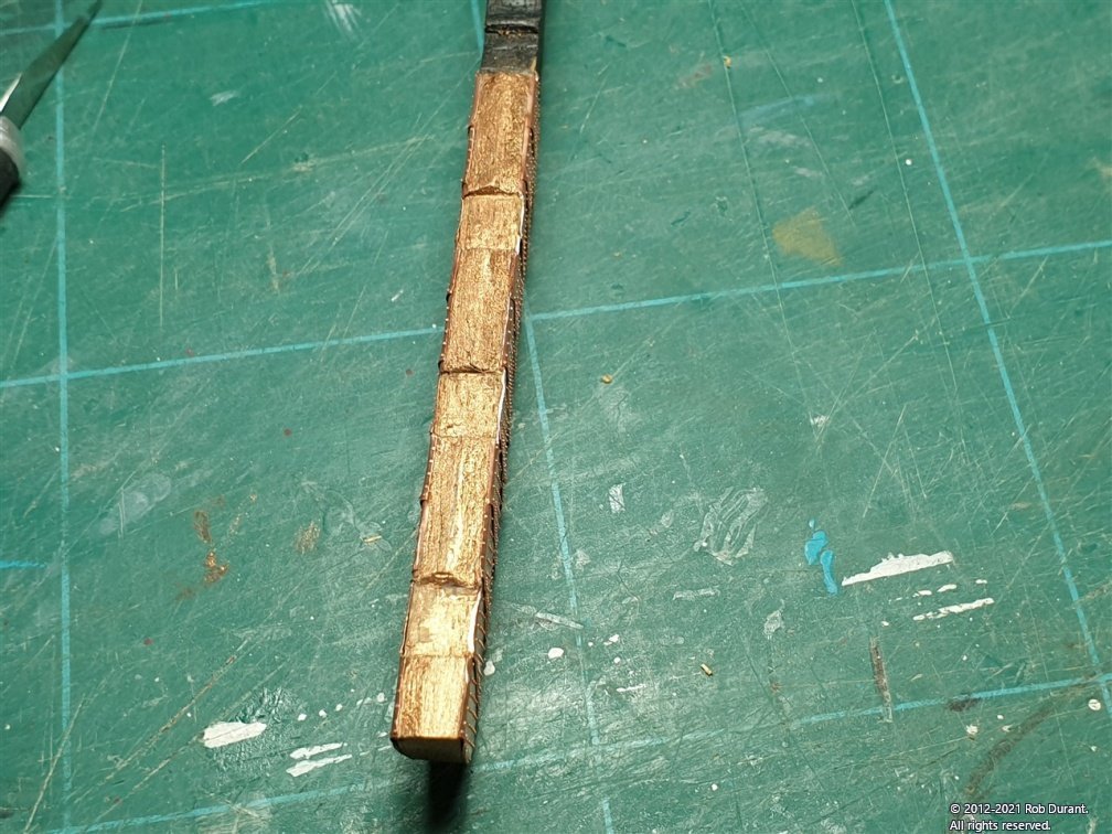
Thank you all for the likes and encouragement It's very very good to be back in action again. Looking at the plans, I realised I hadn't shaped the front edge of the rudder - nearest the hull - before plating it. With some careful application of a sharp scalpel blade, I was able to carve this wood away, and then wrap the copper round, as it now protruded a couple of millimetres in front of the front edge of side of the rudder. Then I got stuck into making the pintles and gudgeons. But real life calls, and I think that subject deserves a slightly more in-depth post, so I'll write about that tomorrow. Happy building, all! Rob