


robdurant
-
Posts
799 -
Joined
-
Last visited
Content Type
Profiles
Forums
Gallery
Events
Posts posted by robdurant
-
-
Jason,
What beautiful work you're doing on the quarterdeck. Any captain would be proud to wear those planks thin by pacing them on the weather-side!
Rob
-
Thanks for all the likes and encouragement.
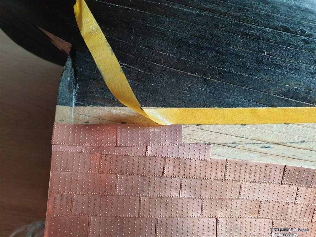
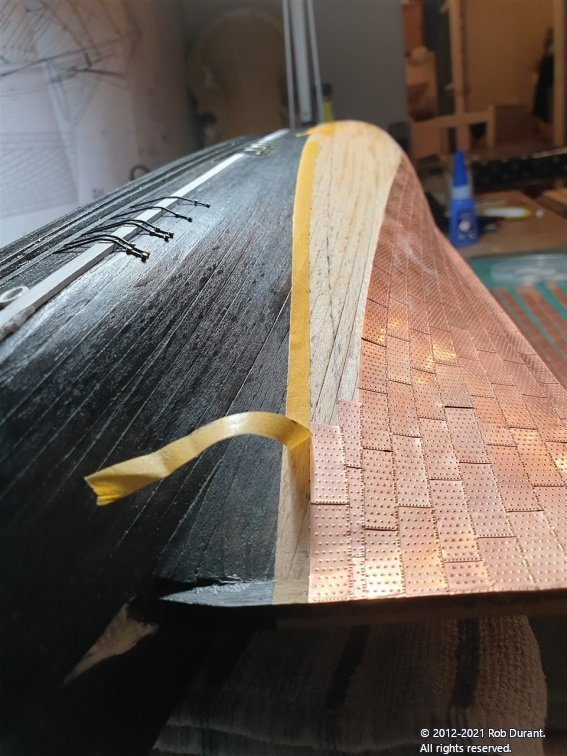
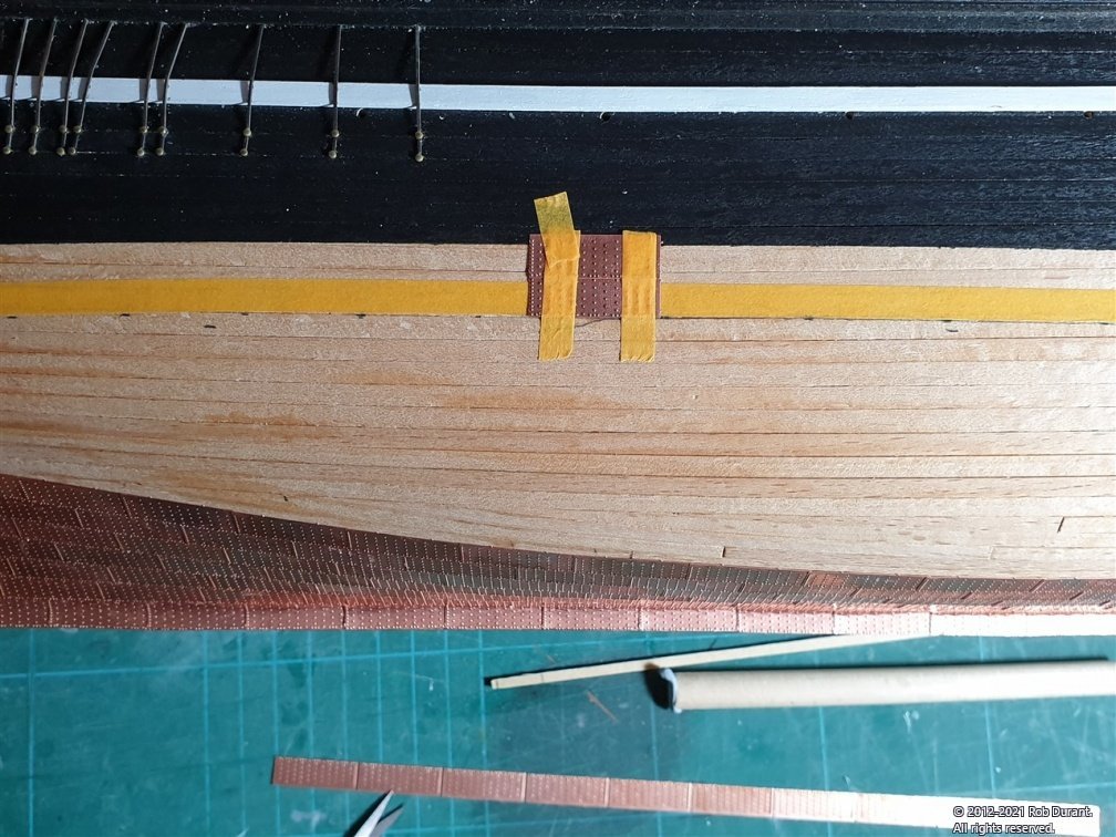
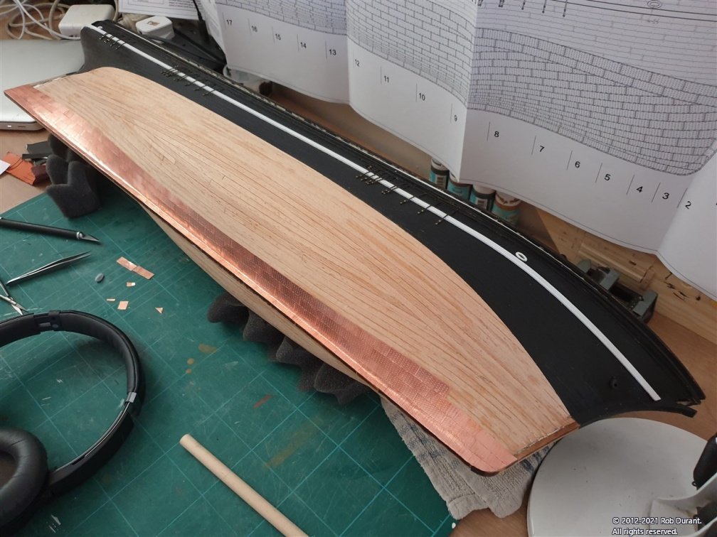
I thought it might be helpful to some if I described in a little more detail how I'd planned out the bands along the top of the plating, when the plates are all laid from the keel up. It presents an interesting challenge, because the shaped tiles must be laid first, then the bands along the top which overlap them. All must be done leaving enough space for the top plates to overlay the lower, and leaving a smooth waterline, and without too much distance between the plating below the bands, and the waterline so that messy gaps are left. In addition, one can't simply leave full tiles underneath the top bands as they have raised rivet detail which will raise them unevenly. Hence they must be trimmed. I wondered whether I might hammer down the detail, but I was unconvinced that I'd manage to do that on the rivets in question without completely destroying the visible area of the tiles.
Here's how I managed it. I measured the width of the bands at the top, and marked that width down from the waterline minus two millimetres. That gave me the line I wanted the plating to finish at below the bands. Once the lower plates reached that line they are now being cut to follow that line. The lower band can then be started overlapping those plates slightly, and leaving 6mm for the upper band.
Hopefully that makes sense. At each sense, I'm making sure I'm measuring again carefully and checking as I go. I'm using 6mm masking tape to keep a nice neat space for the top band (which are the tiles with rivets on the top AND bottom) to finish off. This should, hopefully result in a nice neat line. The waterline painted will be the guide for this.
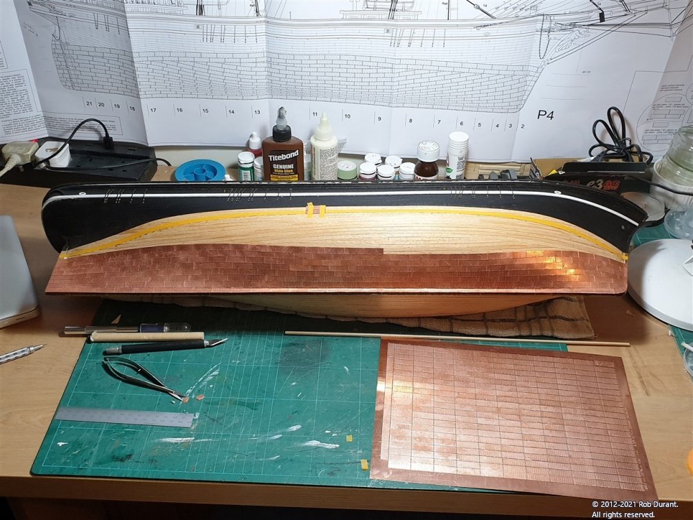
Here are the results so far...
The first photo shows the lower plating cut to the pencil mark (which shows the bottom extent of the two bands, minus the overlap). The first two plates of the lower of the two top bands have been added, with the yellow masking tape giving a guide to make sure sufficient room is left for the top of the two top bands.
The second photo is the same work but from the stern to show the sweep as it goes forward.
And a couple of angles of progress so far.
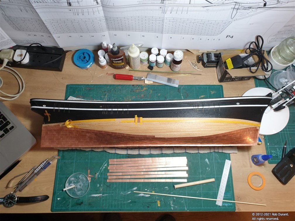
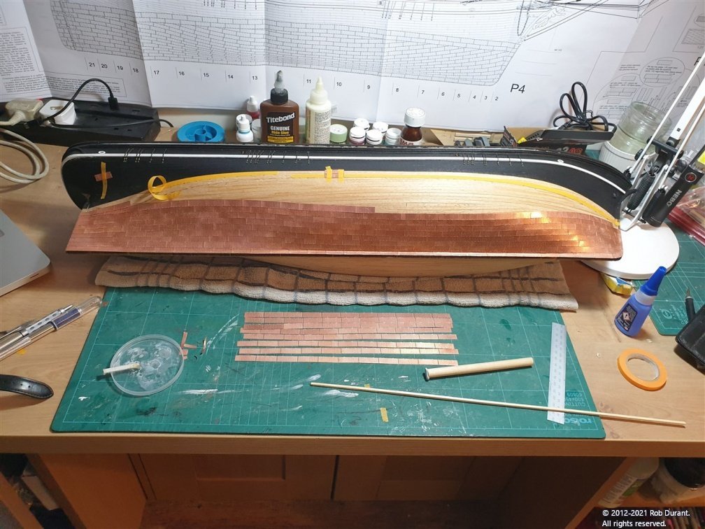
These plates are quite simply cut where necessary with little scissors, so with a little care the job is proving relatively straightforward. I've also realised that the photo etch tags can be easily cut with a scalpel to remove them from the main sheet without any bending. So that's now my preferred method of doing that. Once done, they are then trimmed and separated with tiny sewing scissors.
Happy building!
Rob
-
I've been gradually plodding along with the copper plating. This would have been faster, but I got distracted with another small kit, and took a holiday...
The copper-plating has two rows that run at the top parallel to the waterline. I've used masking tape to mark the bottom of that band (with 2mm to play with), so that I know where to stop the lower bands. These lower bands will be cut to fit the lower edge of this masking tape, and then the two top rows added to finish the job. So the masking tape finishes 13mm below the waterline. It's worth noting that this isn't 13mm vertically, but 13mm as the plates are laid... a fairly different measurement by the time you get towards the stern.
- BobG, GrandpaPhil, egkb and 5 others
-
 8
8
-
Hi Tim
Yes I am at Corsham Baptist. We planted a church 6 years ago just up the road and I spend most of my time serving that congregation.
Ministry has had its fair share of challenges and unexpected opportunities over the past year. But I think we’re doing okay. Hope you, your family and your church are doing well too. I appreciate your prayers very much and have prayed for you this morning too.
One of the appealing things about this hobby to me is that if I have a time when ministry doesn't allow any work to happen on the boat, it just wants patiently and I can pick it up again when I'm ready. Quite rightly family and faith come first
")
I'm glad you like Ethalion. She's still under a plastic sheet waiting for a display case.
Rob
-
From one time-poor church minister to another, that's a very handsome vessel you have there. The detailing around the stern quarter - especially the windows look very fine, and I really like the colour scheme with the copper bottom and the blue accents on the upper works.
Do keep posting your progress
Rob
-
A very good question. To be honest I don't know, but it sounds plausible. Perhaps someone here can tell us.
-
-
11 hours ago, Thukydides said:
I have a question relating to photos. I have been doing my log in Google docs (just so I have a record) and then copying and pasting it into my log her on msw. I have noticed that when I view the log on mobile the pictures appear squished. Is there anyway to fix this?
It's probably because when you copy and paste the pictures it's actually copying and pasting code which will contain style parameters (width / height / alignment, etc..) specific to Google docs which will alter how the forum displays the images.
As Mark says the simple way (and certain) to get the right result is to download the image to your computer then upload it separately. This avoids the code being carried across. The other possibility is that you may be able to paste "unformatted text" which should cut out this code, but this option will probably only be available on some browsers / operating systems and you will lose any formatting (headings / bold / italic etc...) you've put into the log text you're copying at the same time.
When you put the pictures into Google docs do you set the height manually? If so when the picture is shown on a desktop computer there is sufficient width for it to display with the correct aspect ratio (not squished), but when displayed in mobile mode there is perhaps less than a third of the screen width and so it honours the height setting you selected and resizes the width so it appears squished.
The simplest way to avoid this is to resize your photos before you upload them and then leave any further resizing (i.e. for mobile display) to the browser. It will show the image at full size on a desktop and smaller but at the correct aspect ratio on a mobile.
If you edit the posts you have made you should be able to edit the settings for height and width on each image to fix the aspect ratio, but hard coding the values will cause the image to go off the side of the screen on mobiles or to be very small on the desktop.
Better would be to remove the height and width settings entirely and let the browser do the work.
- mtaylor and Thukydides
-
2
-
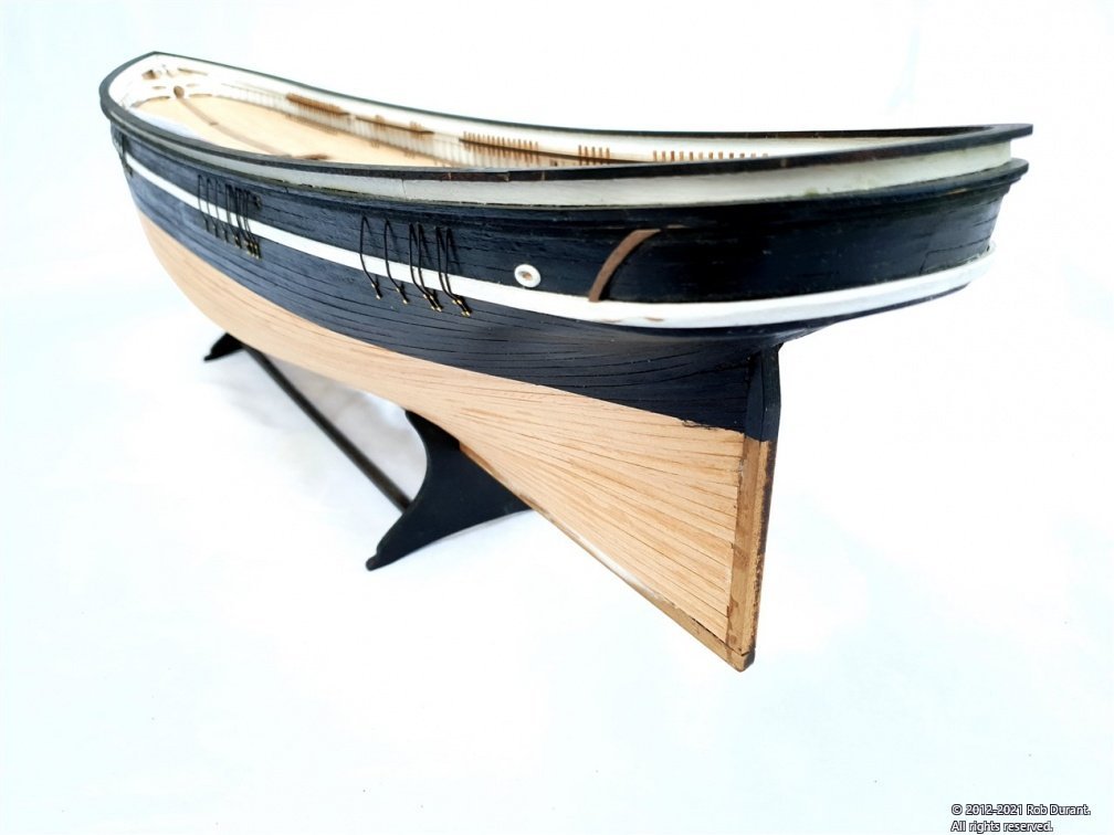
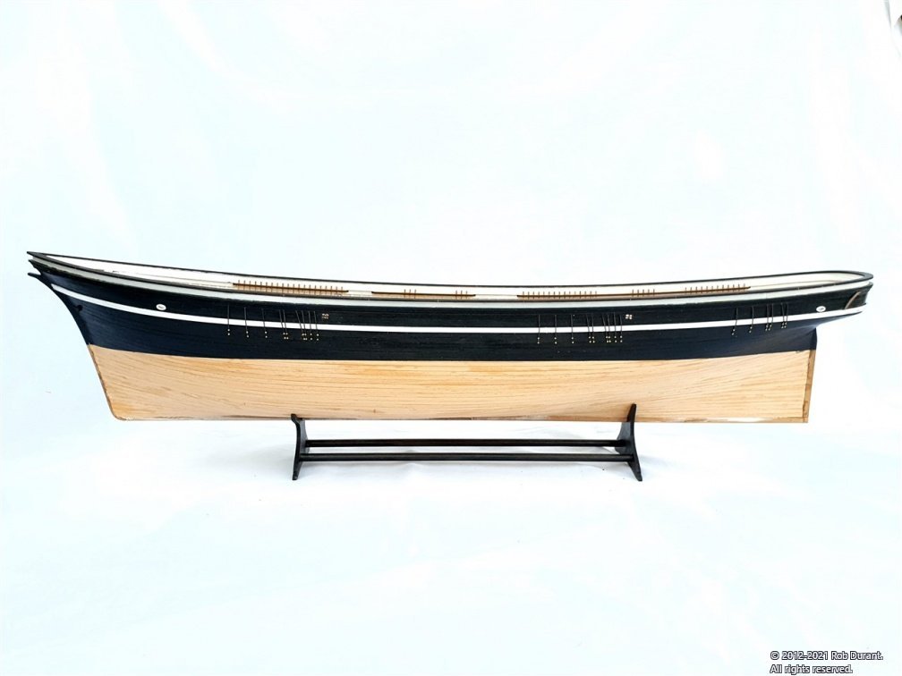
Wow! What a brilliant job you've done of this kit. The quality of work at every stage is very apparent. Looking forward to seeing the finished photos, especially with the ingenious and very effective boat stand you've found. Just sad I didn't find this log earlier. Will you be moving back onto the ARM Cuauhtémoc now? She looks like a very handsome vessel indeed.
Rob
-
Thanks Eurus, and Jason.
8 hours ago, Beef Wellington said:I'd love to see the plates before they go on, that sounds like incredible attention to detail that they supply multiple different kinds of plates for the different locations.
You ask and we deliver 😁
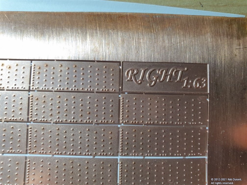
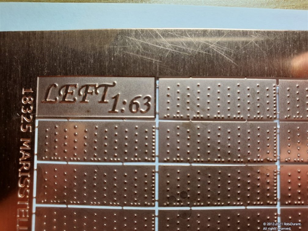
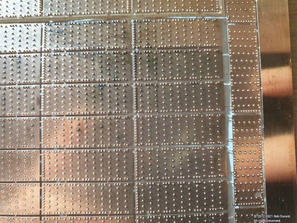
My digital micrometer tells me I've been tricked by an optical illusion... the plates are all the same height. Nevertheless, there are right hand, left hand, and finishing plates. Here are some close-ups of each...
Right-hand...
The Left-hand plates...
And the finishing plates (because they overlap you need plates with rivets along the top and bottom to finish off the effect...)
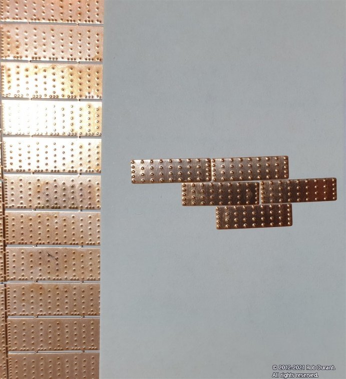
Finally, a comparison between these (amazing!) MarisStella copper tiles (on the left), and the Caldercraft ones I used on Ethalion (which I found fine, but are clearly not as refined as these ones). I don't have any Amati tiles to compare, but I've heard these are also very good. You can see that the rivet detail is much more pronounced on the Caldercraft tiles, and they also have rounded corners. Because they are not -handed, it's hard to overlap them, and so the rounded corners result in a tiny diamond gap where they are butted up against each other. I've also noticed, already, that the overlap makes it much more forgiving to go round curves with the MarisStella tiles. They're also a bit bigger, so they cover the area more quickly. All in all, they're an improvement.
The MarisStella tiles seem to tarnish quite quickly, but I'm hoping if I'm careful with the superglue, and I give it a good clean when I'm done, over time this will result in a pleasing patina.
-
Hi all,
Just back from a lovely holiday, camping up in the Midlands (of the UK), but before I went I did manage to make a little start on the coppering of Stefano. She now has four bands of the starboard copper tiles. I was wondering how I'd get on with this, as they have to be cut out individually, but it was fine. I used some little sewing scissors to cut the ends and then bent a row off the rest of the fret. The scissors were then used to separate them and trim excess sprue. They overlap beautifully (being -handed), and the whole process is well described on the plans.
Here's progress so far. (I put a little card in using carpenter's glue to make up the over-narrow stern and prevent a dip in the plates... it'll all be invisible, so only myself and anyone who stumbles upon this topic will ever know 😇 ) I'm quietly optimistic about how this is all going to work out. At some point I shall need to put the rows along the top, but I thought I'd put this off for a little while as I got used to the tiles themselves. It's worth nothing that the top row has rivets along the top AND bottom... also, there are specific tiles to go under the keel. Again, with rivets on both sides, and I think they're a little narrower, perhaps.
-
Painstaking work but the results speak for themselves. She's looking great! Really nice progress.
-
-
1 hour ago, gak1965 said:
...I would glue them in place personally...
Hi George,
I really appreciate the advice... I've just finished the other side, and some of these have been glued in place, as the holes were not quite so tight, but I will go over them all again and try and remove them to stick them in place.
All things said, I'm really pleased with how they've come out. Here's the final sweep. (I'm also pleased that the drilling was much neater on the port side! - a little more care and attention in marking things up)
I have a few eyelets to put in place, and then it's on to the coppering! I anticipate buying a large number of superglue bottles over the coming weeks! And I'll need to dig out my vapour mask again.
Thanks for the likes, advice and support
Always much appreciated.
Rob
- egkb, coxswain, Beef Wellington and 2 others
-
5
-
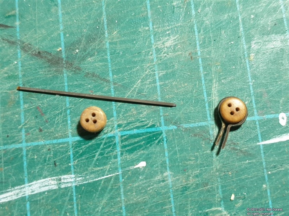
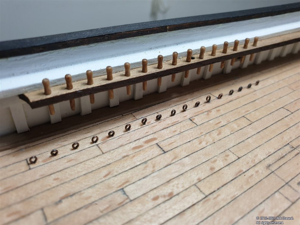
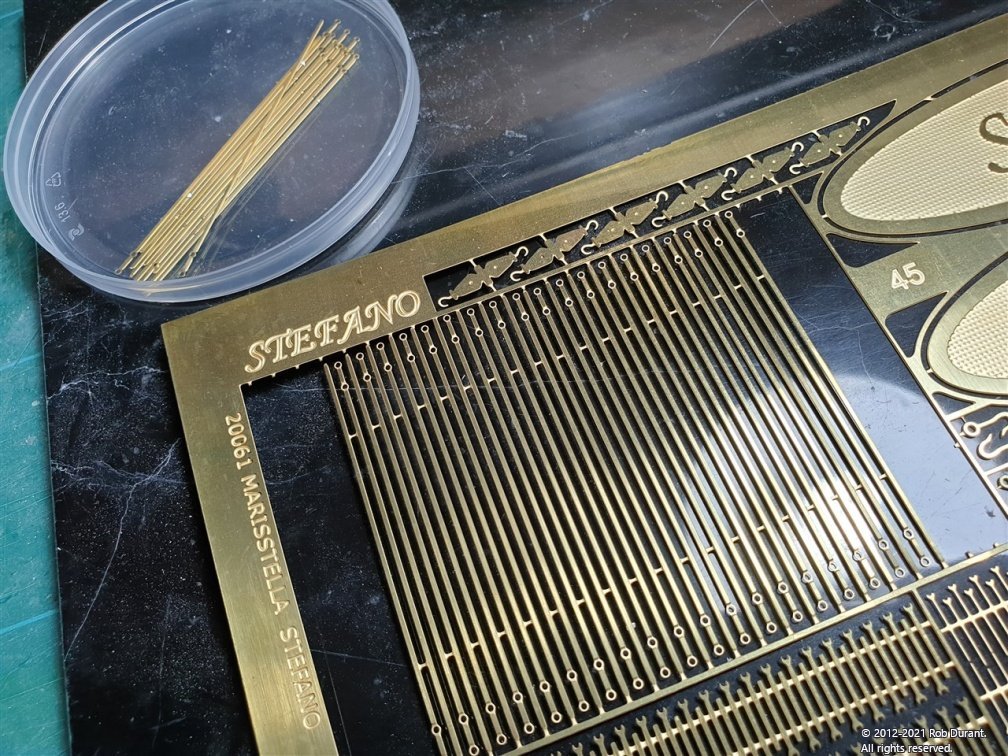
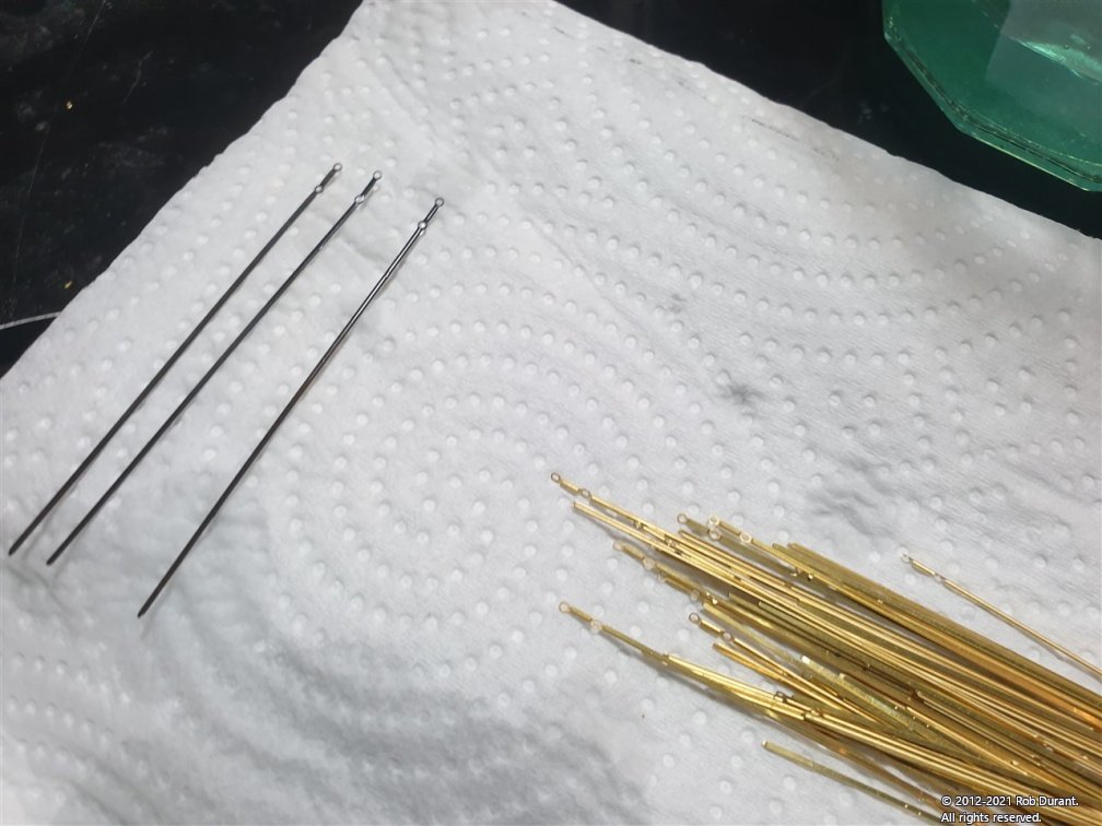
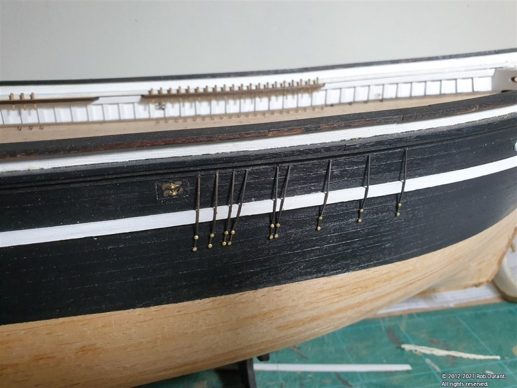
I've been working on the deadeyes. The instructions call for twisting wire to mount these to a 2mm eyelet. However, this seemed like it would leave a twisted wire at the top, or perhaps between the deadeye and the eyelet. Would this need soldering? And how would I blacken it, if so.
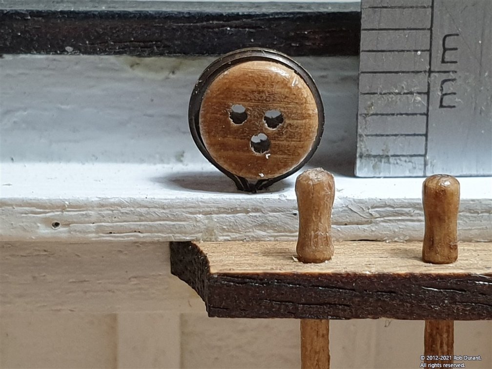
In sum, I wasn't quite sure how to neatly attach blackened wire to the deadeye, and at the same time be confident that it wouldn't come undone at an inopportune moment as I was rigging stays, or similar. So, I decided to forego the eyelets in the rail and directly mount the deadeyes using the cutoffs of the chainplates (as these were plenty long enough for the purpose). This way, the metal would look identical to the chain plates mounted to the side of the hull.
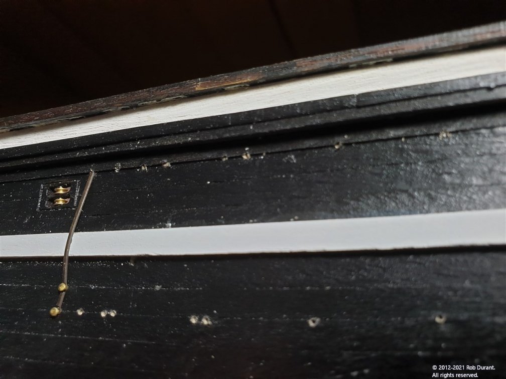
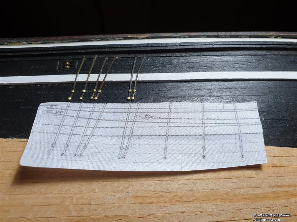
Here's my progress so far. They are (tight) push fit into a 1mm hole, but remarkably solid. If any so much as wriggle I shall glue them in place with superglue, but I have exerted a fair amount of force and they don't shift so far.
-
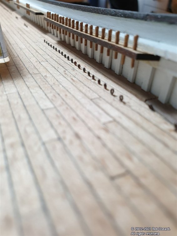
I've finished the simulated chain plates, so I thought a few progress shots were due.
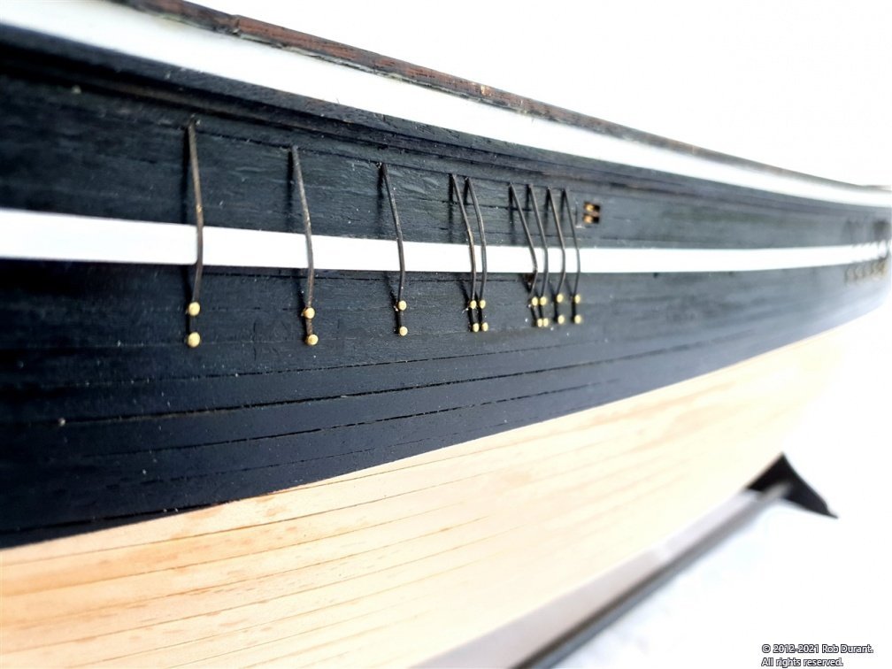
I ended up with one chainplate photo-etch part left, so do be careful with these parts (especially that you don't cut them too short, which would be easy to do if you forget to take into account the angle in towards the hull from the wale)
There's a little painting to do at the stern to touch up where I've sanded down the detailing to make it flush with the wales, but otherwise Stefano's looking quite smart.
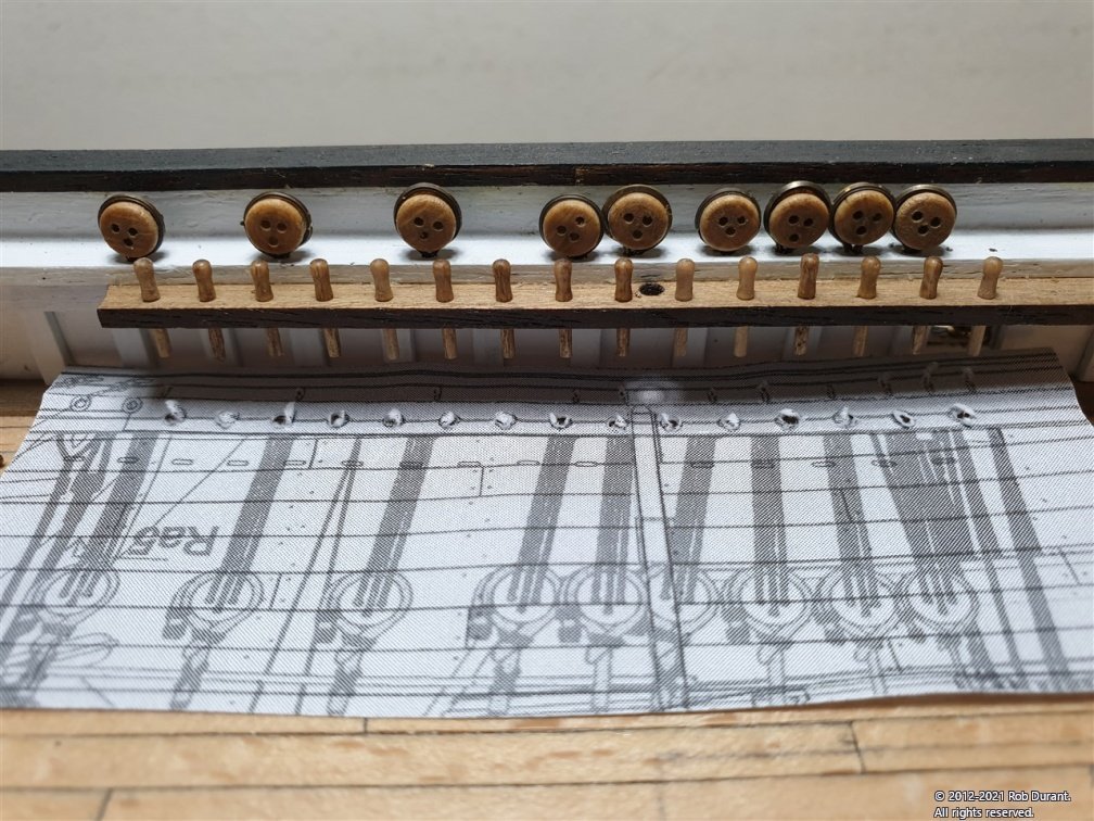
Next step, attaching the deadeyes to the main rails to complete the illusion that the chain plates pass through the hull.
Rob
-
-
Hi all,
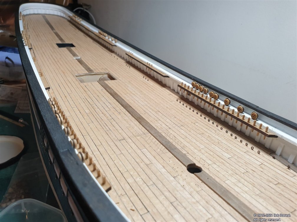
A small update. I've added the eyelets on the deck, drilling the holes using the template I made for the deck. This kind of worked, although in retrospect I would have gone back and neatened up the marks a little before I actually drilled them.
I've also completed the (faux) chain plates on the starboard side. These are attached like chain plates, but actually stop where they enter the underside of the rail. The deadeyes themselves will be glued into the rail on the top side. Careful comparison of the top down and side elevations were necessary to ensure these match up, and will look right compared to the mast position / pin rails, etc...
This was done by overlaying the two elevations on the computer and printing out the resulting overlay to cut out and place on the model. The chainplates themselves are photoetch, and look very flimsy, but I was surprised by how sturdy they actually proved to be. They were blackened before fitting with brass pins (a 0.8mm hole was drilled to accommodate the lower pin for fitting, and then once fitted the position of the upper hole was marked and drilled. This ensured the two holes lined up as hoped.
Small sewing snips proved to be the best tool for removing the chain plates from the photo-etch sheet.
You'll notice that the remained of the belaying pins also arrived from Cornwall Model Boats, so those have been put into position. It blows my mind that I'd pre-drilled the holes for these wooden components before they arrived (to 0.6mm), and they were a gentle push fit when they arrived... every single one of them! I wish I could work with that kind of precision and consistency!
Happy building, all!
Rob
- coxswain, BobG, Beef Wellington and 2 others
-
5
-
Very nice
Looks like you're making great progress! I made my own window frames too. Plenty of work, but I'm really glad I did. It is a real feature of the vessel.
As far as the gratings go, I made up all of mine in one go, and only once they were done did I notice that the gratings on the quarter deck and fore deck have much narrower coamings than those on the gun deck. I didn't want to remake them all, and wasn't confident I could do a good job of cutting them down, so they're all a bit overscale on my quarter deck which makes things a little crowded. Oh well... next time!
-
2 hours ago, dunnock said:
I’ve started to think about the stern and quarter galleries.
As a note, do be careful with these, as they're very easy to put on too high or too low. Photocopying the plans and sticking them to the side of the hull will help you here. Also, if in doubt, make card templates of the ply parts and try it out as a mockup (they're easier to bend and manipulate before you bend the parts!). It took me a good while to be satisfied it would all fit together, and I ended up pinning parts so I knew when I glued them they'd go where I'd intended them to go.
The line where the top of the stern lights finishes will determine the intersection between the bulwark rail and the capping rail over the transom. And it will also determine how the lights look as they transition between the quarter galleries and the stern... which for me is a line that the eye picks up on (one of those "you'll never notice it if it's right" things?) and makes a big difference. Anyway - I wish you all the best as you set out into perhaps the most challenging, but also the most rewarding section of the build!
- DaveBaxt and Beef Wellington
-
2
-
What a fantastic coppering job! The transition between the stem and the bow is particularly neat. Looking at those photos I realise just how much the copper has toned down on mine already... a much more mellow shine. Without the comparison I hadn't really noticed it happening. The black line at the top of the copper really works well.
Whenever people visit my house they're always slightly shocked that we glue these tiles on one by one... I guess you have to love the hobby to understand why we would. But it sure feels good to glue on the last one!
Looking forward to the next update.
Rob
-
Hi Jason,
It is refreshing - no gun ports, no gun carriages, no breeching ropes or gun tackle... No elevation quoins... And no worries about catching the barrel and sending it into the hull out of reach, either!
I decided to glue it in, and with the 90degree angle between the strake and the underside of the rail it seems pretty solid. Given how narrow they are, I don't think the force on them should cause too much trouble. It'll be pulling them into the rail above. I'm in awe of the guys who could find the right belaying pin in a gale in the middle of the night with the deck pitching and waves washing over them. Especially when you realise these great machines were being operated by a handful of skilled crew! Brave stuff. If my model were going to go through that, I'd definitely want the rails pinned!
Rob
-
Great work Jason. I'm sure you'll be really pleased you tapered the planks. My approach was a little less precise but still it makes a nice contrast to the straight planking runs on the gun deck. As a thought you may want to put some of the planks down then reassess the widths to make fine adjustments in case laying the planks introduced some drift? But your planking is so precise I'm sure you'll be fine.
My digital calipers are the tool I never put away on my build desk. Especially useful when you need to work put which drill bit you need (and what order they go back in the box when you accidentally drop them!).
Looking forward to seeing this deck come together.
Rob
-


HMS Ethalion 1797 by robdurant - FINISHED - Caldercraft - 1:64 - Modified from HMS Diana 1794 kit
in - Kit build logs for subjects built from 1751 - 1800
Posted
Thank you") I look back at her now and can't quite believe I built her! A testament to the excellent kit design and great encouragement, ideas and resources on this site!
I look back at her now and can't quite believe I built her! A testament to the excellent kit design and great encouragement, ideas and resources on this site!