


robdurant
-
Posts
837 -
Joined
-
Last visited
Content Type
Profiles
Forums
Gallery
Events
Posts posted by robdurant
-
-
-
Thank you for the advice and the encouragement, Rob. I don't own a drill press, so it will just be a case of marking it out and being as accurate as I can with hand tools.
I think part of the problem was that I was drilling the holes too small, and then in the process of trying to push in the eyelets, I was bending the wire. Practise should make better, if not perfect, and I'm not scared of a do-over.
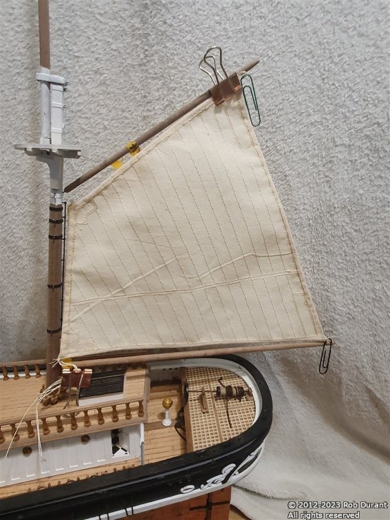
I've been doing some more work hemming the sails for the foremast...
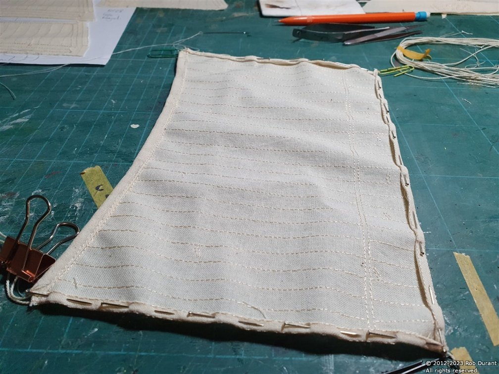
The paperclips stop the loops on the rope from disappearing into the hem until they're finally fixed. That should happen when I sew the bolt rope on to the edges of the sail.
- Keith Black, BobG, Prowler901 and 3 others
-
 6
6
-
Thank you, all, for the likes and encouragement. It does spur me on
")
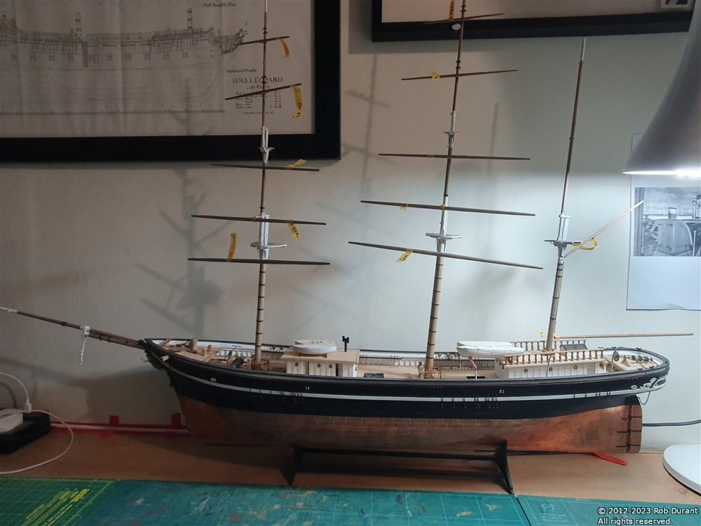
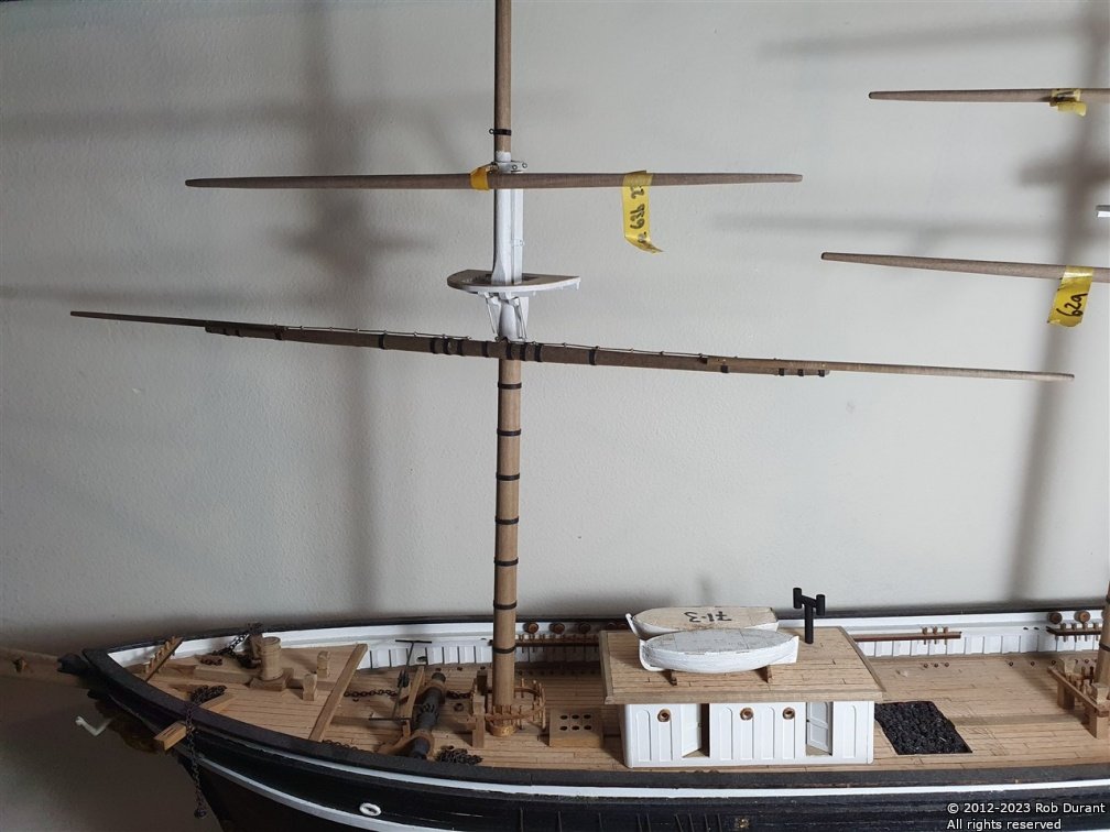
Work has moved on to completing the yards. I've begun with the lowest yard on the foremast. I've added black cartridge paper banding, and had a first attempt at the rails that the sails are attached to. I'm not quite happy with these yet, but it's soldered so I can go back and have another go. I've also decided to build Stefano with stuns'ls deployed... it'll make the model a full 15cm wider than if the stunsl booms were retracted, but it'll also make her a very imposing sight indeed... so... I'll go for it, and worry about where I'll keep her later!
The first photo is one of my cleared up boat desk with Ethalion in the background...
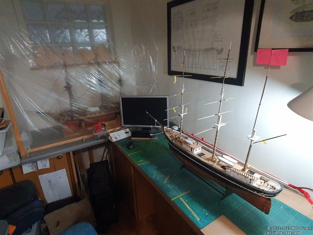
With the masts rotated, she pushes to the back of the desk and that gives me room to work on whatever's going on that day.
And a couple of photos of the progress on the foremast main yard.
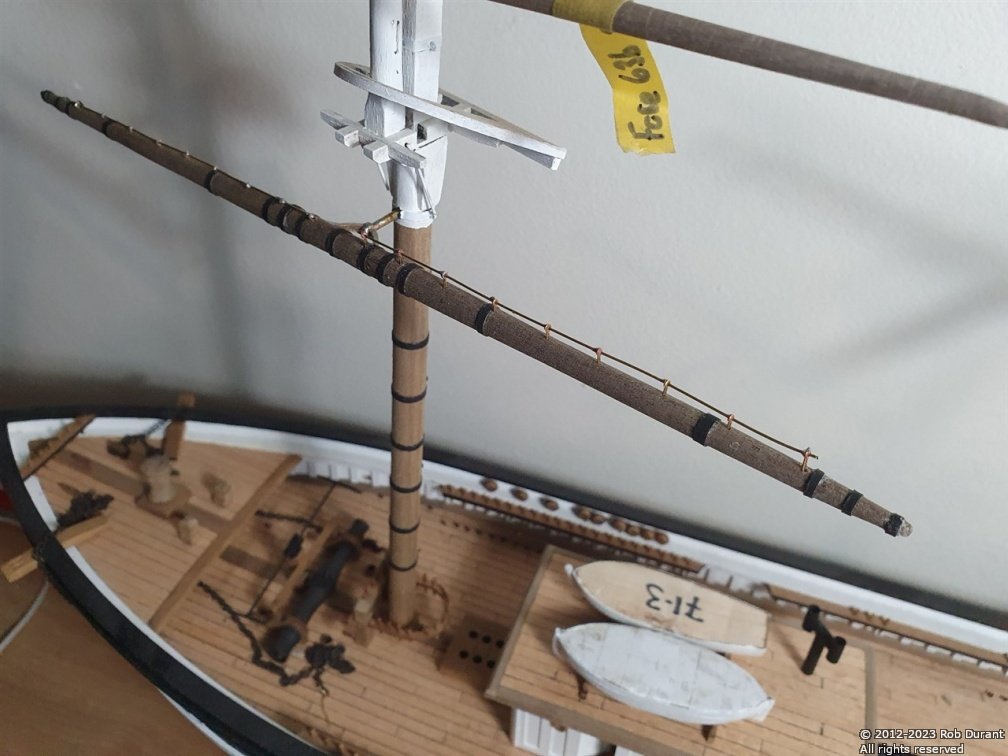
And with the stunsl booms attached temporarily... These are pinned in place, and then black cartridge paper will cover these attachments to look like the iron bands that would have held them in place.
That's it for this evening. Happy building, all.
Rob
- GrandpaPhil, ccoyle, Prowler901 and 4 others
-
6
-
 1
1
-
Okay - time for another update. Version 1.10 - If you select the option to modify individual images as they are resized, you will now notice that there is an option to modify the saturation, hue and luminance for each image. This allows you to make them black and white for example, by reducing the saturation to the minimum.
The functionality is described in the documentation, which can be found here:
PictureResizer.Documentation.20221222.pdf
And the app itself is on the website:
https://www.durant.biz/pictureresizer/
As always, this is programmed in my spare time to try and be helpful, so I do all I can to make sure it will play nicely, but you do use it at your own risk.
I've started playing with cropping, and hope that there might be the possibility of cropping images before they are resized someway down the line. I know it's possible, but I haven't managed to get it working reliably yet, hence I'm not sending it out into the wild
Watch this space!
Take care
Rob
-
Thank you all for your likes, and for showing an interest.
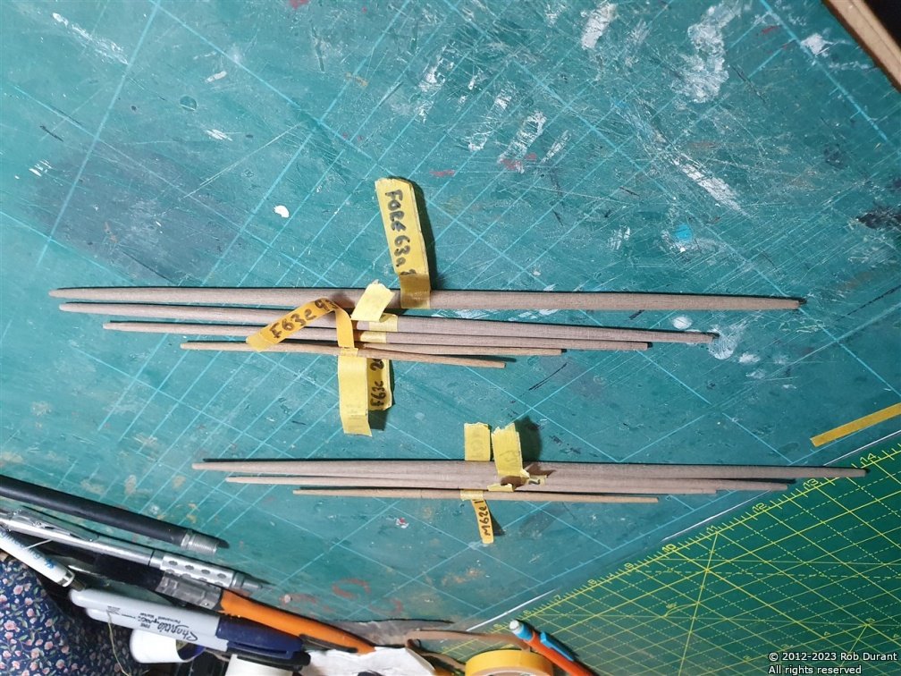
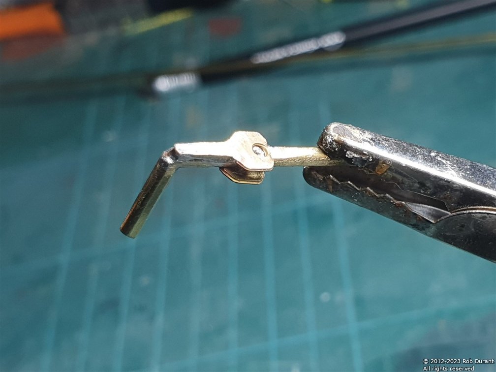
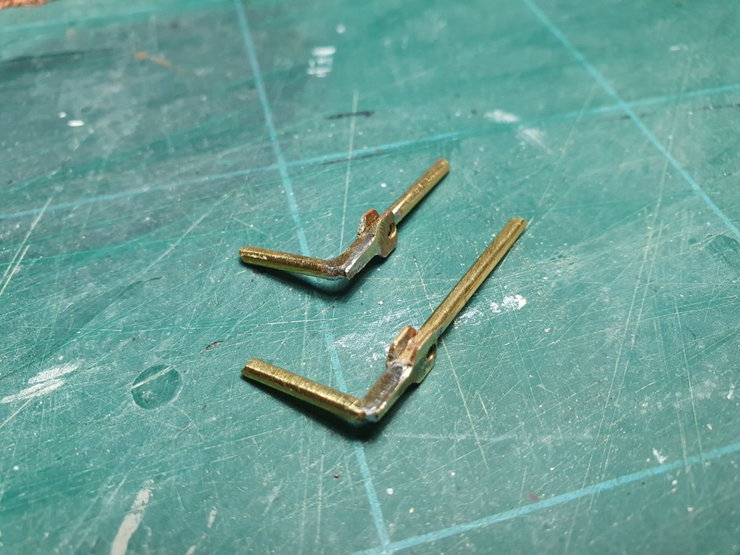
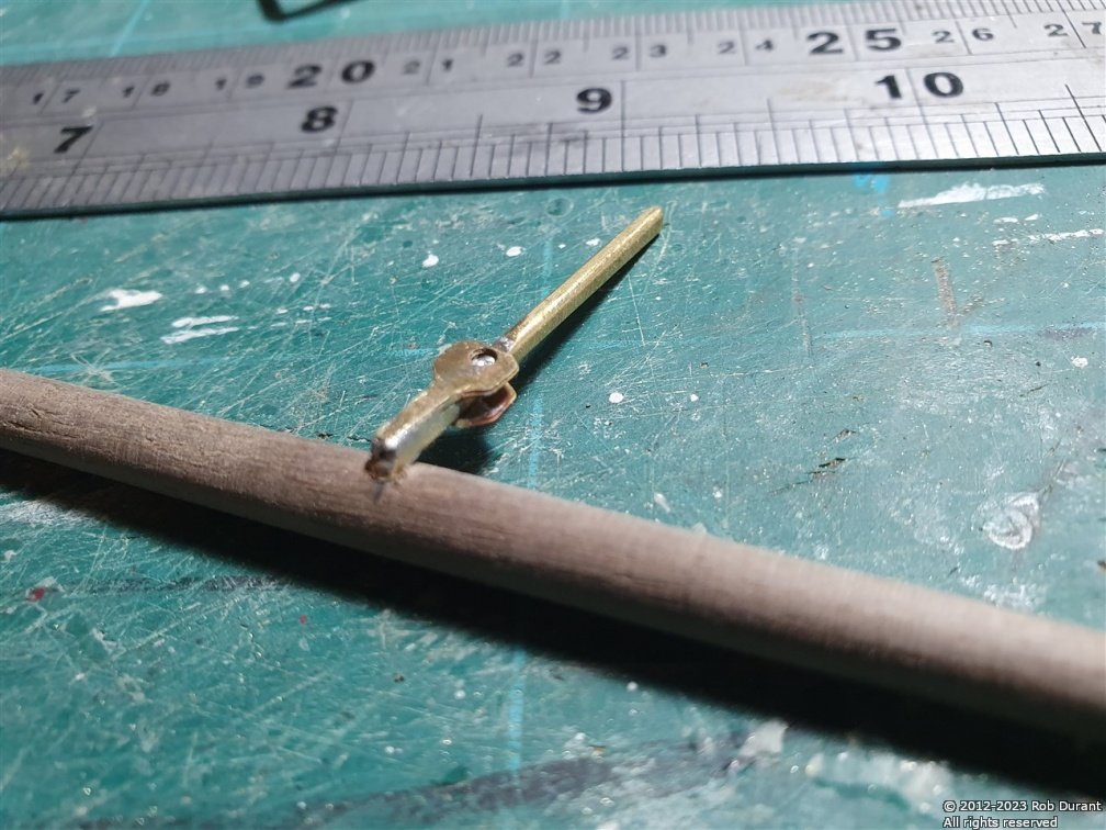
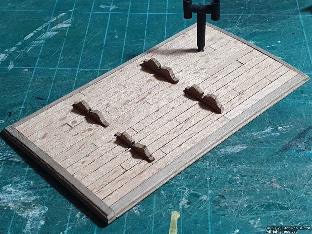
I've finished mounting the yards today. This involved making up the lower yard attachments, which are constructed from two layers of photoetch, with 2mm brass rod. I've simplified these somewhat to strengthen the attachment.
Here are the original parts...
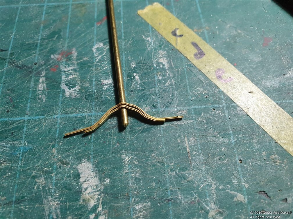
Which are soldered together...
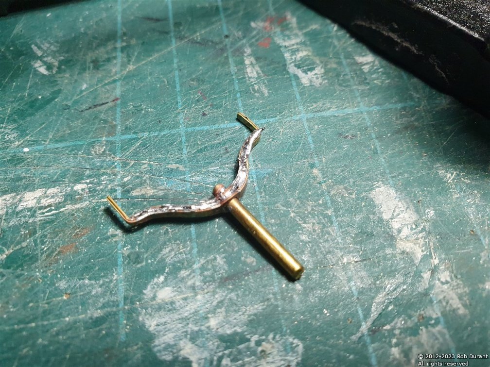
And then tidied up with jewellers files...
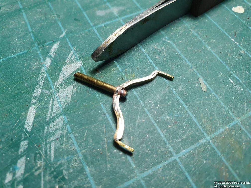
And here it is in place...
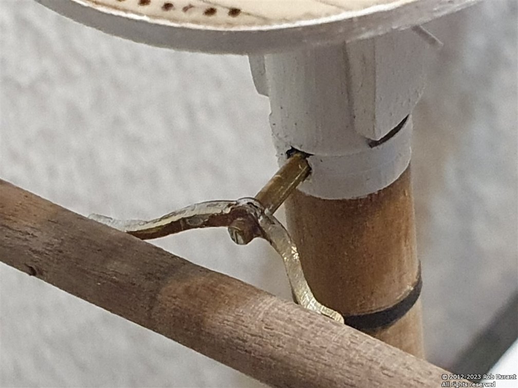
The yards were now mounted to the yards...
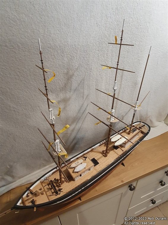
And I couldn't resist temporarily trying the part-completed sail in place, too...
Now, I need to do a bit of tidying up
Happy building and a happy new year to you all.
Rob
- Keith Black, Prowler901, BobG and 4 others
-
7
-
2 hours ago, rwiederrich said:
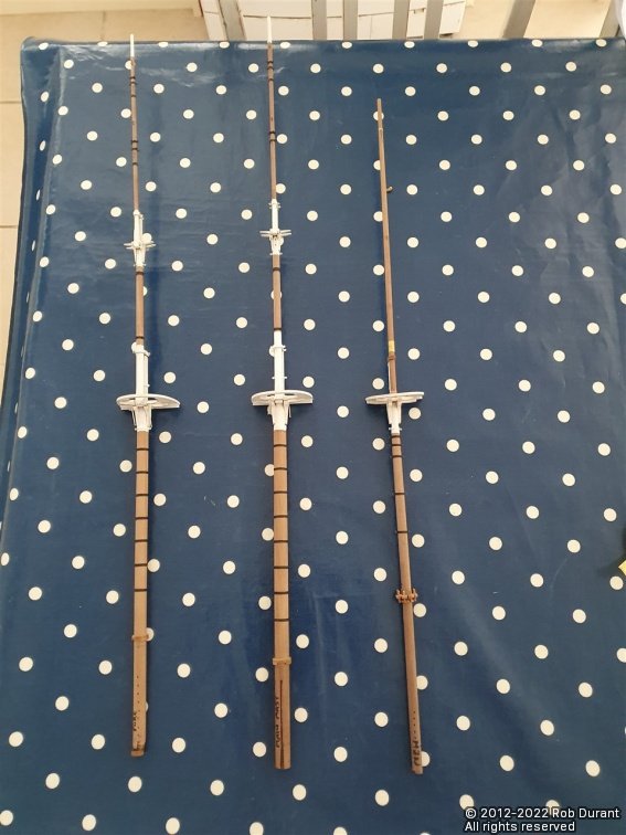
Fantastic work Rob. She is looking amazing and the choice on the kit sales looks fantastic too. What was your method for tapering the yards, did you use a small lathe or did you use a drill motor and sandpaper?
Just beautiful.
Rob
Thank you Rob for your kind words. I use a small proxxon db250 lathe. It really does make the task simple. A tool I haven't regretted investing in.
-
Hi all,
I finished turning the yards yesterday.
I also started work on the fittings that attach the yards to the mast. The top three yards on fore and main yards are laser cut, and the bottom two, photoetch. Unfortunately the photo etch does not leave the spare metal where it is folded and so I have not been able to form these as suggested in the plans. Instead I used brass rod and soldered parts of the photo etch. They will not be articulated, but they will be strong, which is a good thing.
- ccoyle, Keith Black, Rudolf and 1 other
-
4
-
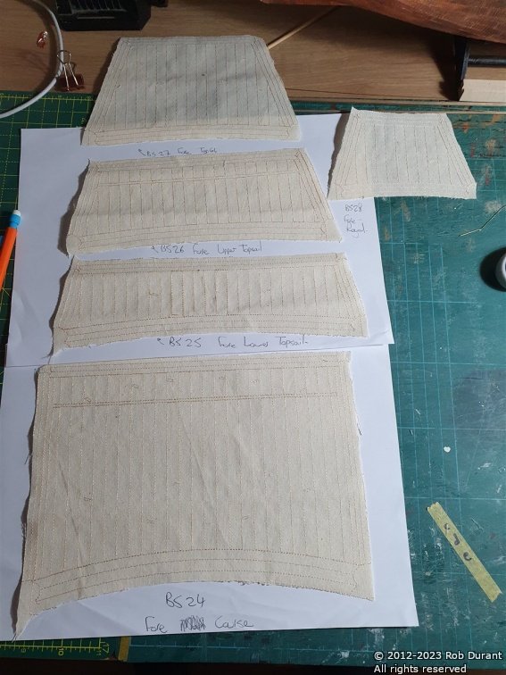
I've spent a while trying to work out how I could paint modelspan to represent sail cloth, but I seem not to have the knack, so having worked my way through a fair bit of acrylic paint and not come out with anything I was happy with my attention turned back to the sails contained in the kit.
The sails have to be cut out and then double hemmed, with a 0.75mm rope (3strands, 1 threads per strand, #20 DMC Cordonnet) worked into the second fold. I've chosen not to include any glue (because it easily creates ugly watermarks) and to simply sew the hem. Sadly my sewing skills are not as good as I might hope, but I was pleased enough with how it turned out.
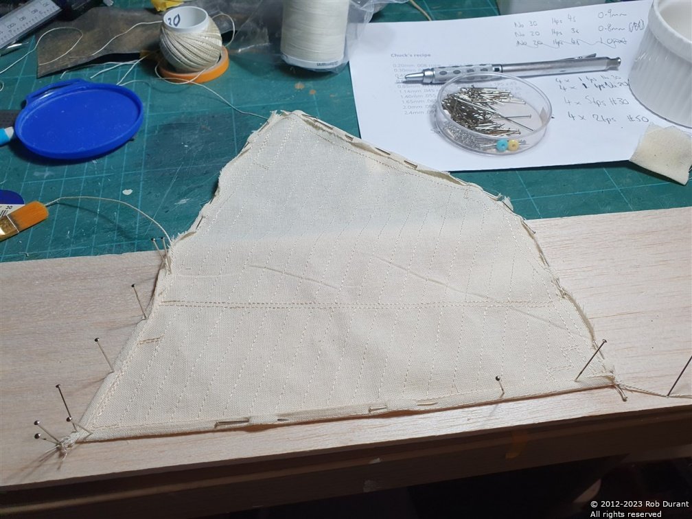
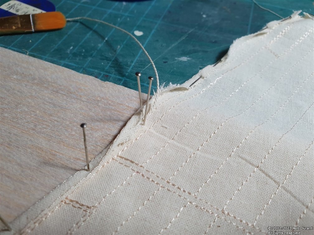
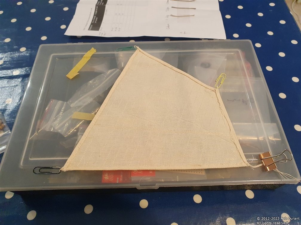
There's plenty more to be done yet, but it's not a bad start. The next step should be to stitch a bolt rope round the periphery.
- Prowler901, dunnock, Keith Black and 2 others
-
5
-
Happy Christmas everyone.
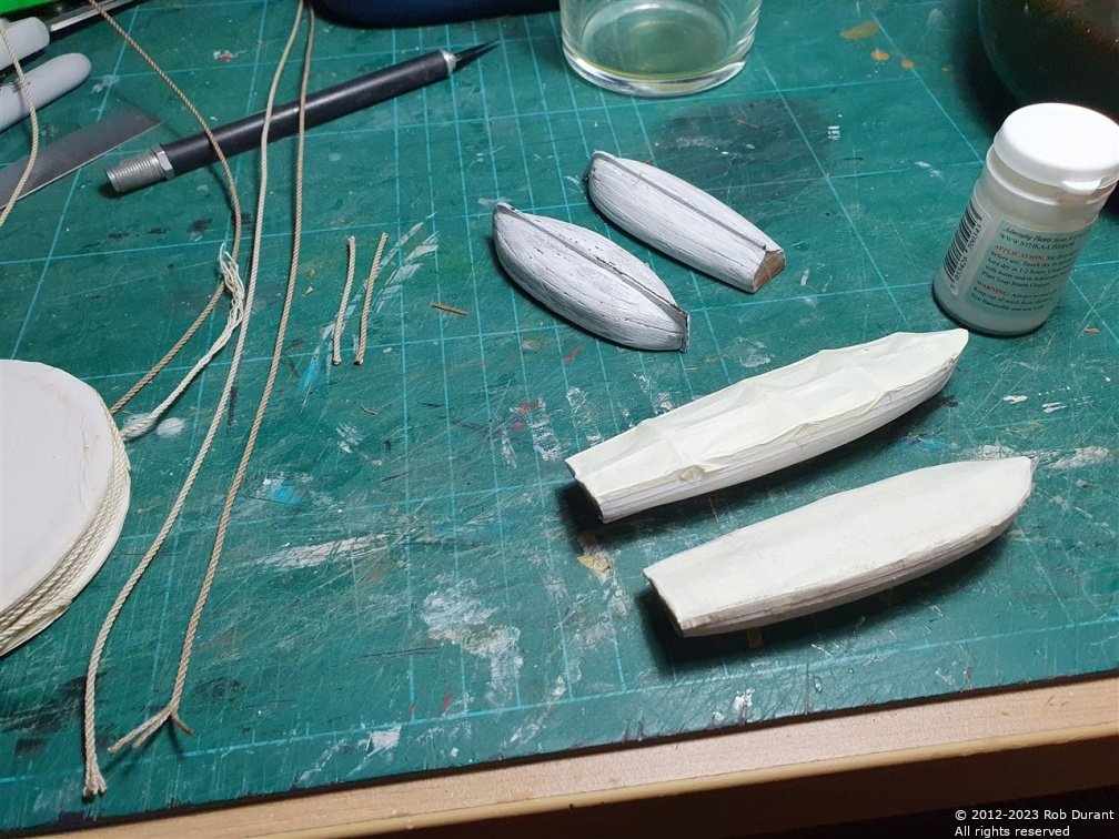
I have a little progress to report. I've almost finished the ship's boats, and I've added the stands to the deck house roofs.
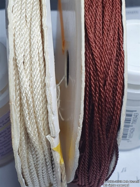
I've also been working on rope-making. I've worked out the combinations I want to use for some of the standing rigging now, using the rope-rocket. Namely:
Lower mast stays: 4 strands at 2 threads per strand of No. 50 DMC Cordonnet crochet thread (makes 1.1mm rope)
This is then coloured using Rit Cocoa Brown dye (I tried using Colron wood dye, but it seemed to have very little effect on the rope) - approximately 1 tsp of dye for 500ml water, with a few drops of washing-up liquid. This is heated gently on the hob, and then the rope dipped in it. I tried simply dipping the rope in, but it tangles horribly. I've also tried drawing it through, but this is horribly messy. Finally, I tried making hanging the rope loosely coiled from brass wire - this allows me to dip it and draw it all out in one go.
I've also been working out the best way to do the sails, but I'll post that as a separate entry.
- Keith Black, Prowler901, ccoyle and 1 other
-
4
-
-
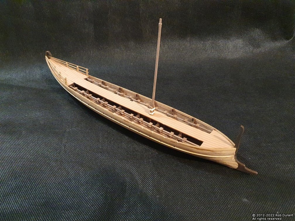
As promised, albeit slightly off-topic - here are a couple of photos of the Bireme I've just completed...
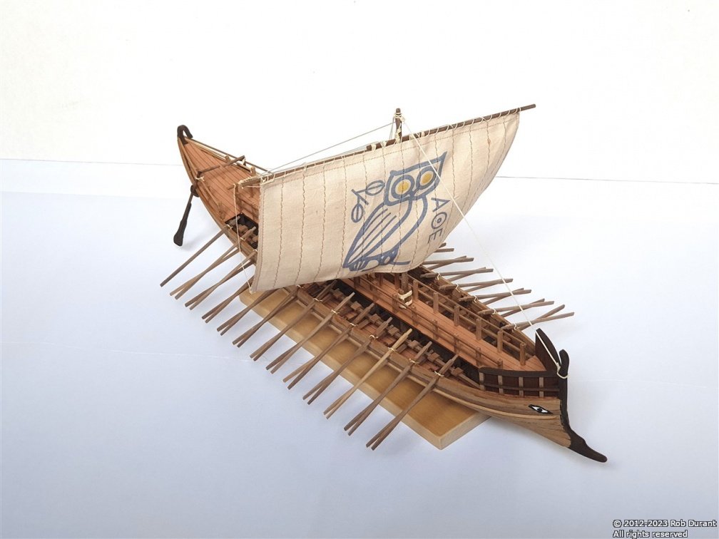
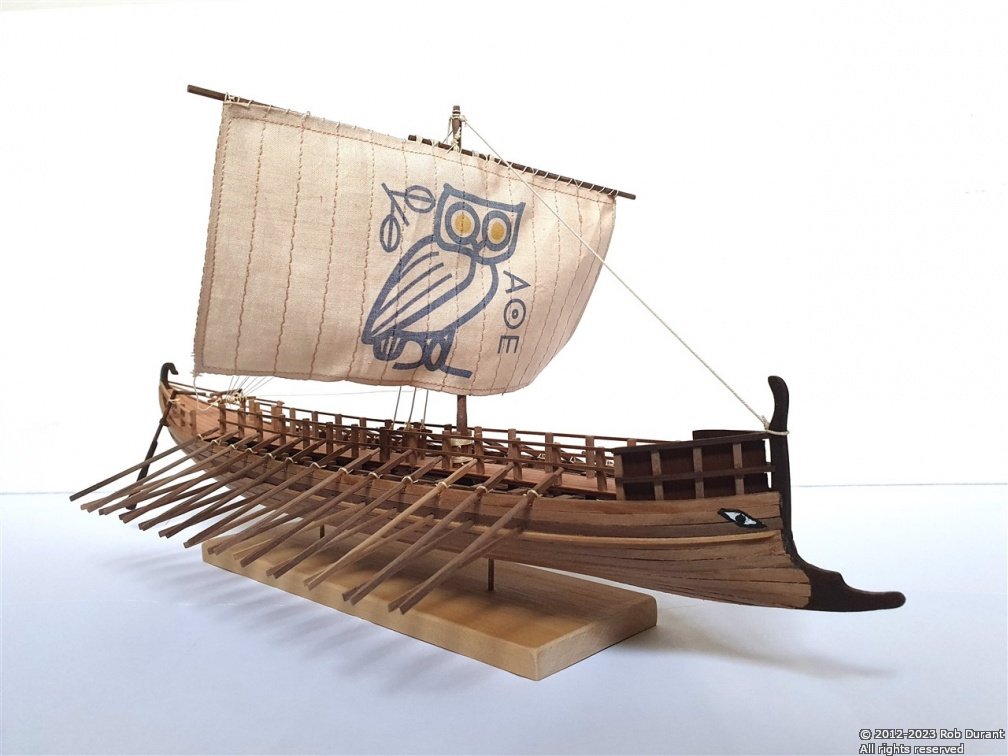
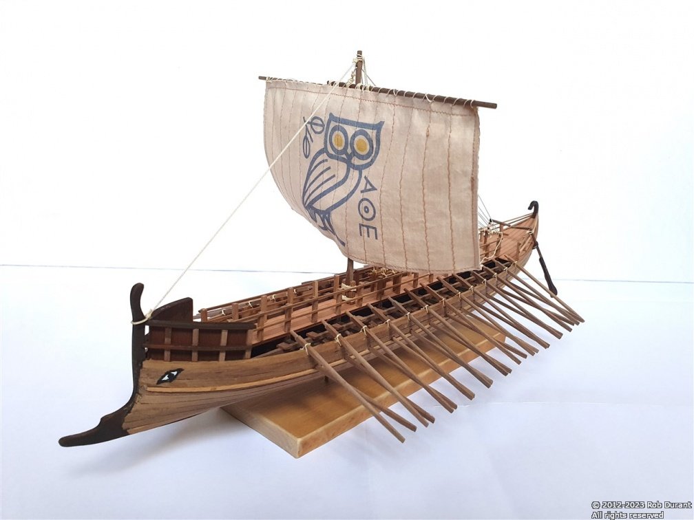
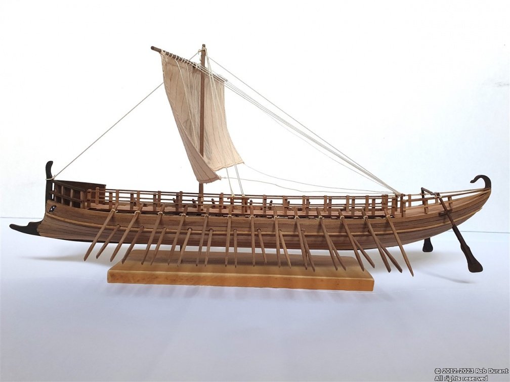
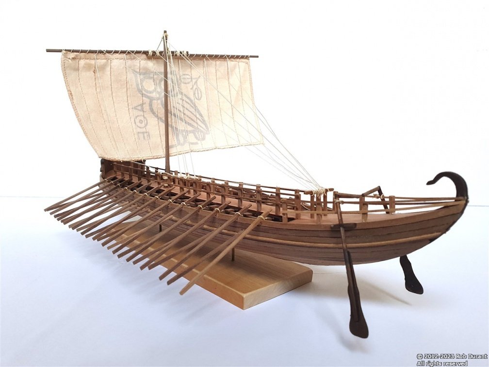
I'm really pleased with the results. Not perfect, but pleasing, nonetheless, and not too bad for a first attempt at a rowed vessel. Happy building to you all
Rob
-
Well, life gets busy, and suddenly months have passed. I've finally finished the Greek Bireme, which I've named Ἀθηνα (Athena). It has the Owl sail, and will soon be setting sail for its new home. I haven't taken the final pictures yet, but I'll post a couple here when I do.
Having finished the Bireme, I'm now able to pick up work on Stefano, which I'll admit I was somewhat daunted by. Today I've managed to get my head back into the things I was trying to accomplish.
The cleats (part 70) are 2mm walnut, and I was concerned they would simply disintegrate or pull off the rail when they had rigging attached to them, so I've replaced them with some metal cleats I had left over from my Ethalion build. These have a 1mm rod on the bottom that provides for a stronger connection.
I've also picked up the work on the lifeboats and adding the lifeboat stands to the forward deckhouse roof.
Only a little progress, but it's good to be moving forward again.
Happy building, to you all, and I hope you all have a wonderful Christmas!
Rob
- ccoyle, gak1965, Keith Black and 7 others
-
10
-
Love those props... looking really smart, now.
-
-
-
-
4 hours ago, BobG said:
That's a beautiful looking ship also!
Thank you Bob. A simple build, but a very enjoyable one.
-
Right, an update is long overdue. Not a huge amount to show on Stefano, as I'm working to finish off the Greek Bireme I'm building for my wife...
I've finished putting the eyelets onto the masts.
There's still some detailing to be done, but they're getting there.
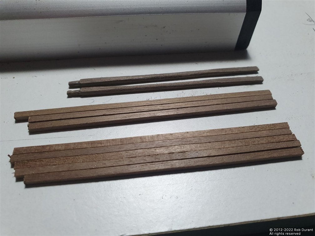
In Greek-Bireme-land, things are moving ahead, too... I'm making oars now... one by one, by one, by one....
More soon, hopefully.
Happy building to you all.
Rob
- dunnock, Keith Black, ccoyle and 6 others
-
9
-
Hi Valeriy,
I echo all of the high praise being given for this superb model.
I wondered whether you used some form of stamp to create those cross-shaped pieces for the flywheels? Or are they cut out by hand... regardless, the accuracy and consistency of your work is quite astounding.
All the very best wishes for you.
Rob
-
Looks like you're well set for an enjoyable build. Hope you don't mind my following along.
-
When you add pictures to your post, so they show in the attachments box just below the text, but then you don't insert them into the text, they are automatically added at the end of the post instead... you can remove then if you want by editing the post, hovering over that attachment in the box under the post text and clicking the black x on the top right corner of the attachment you wish to remove.
You've done a beautiful job with this model. The varnish has brought out the wood really nicely. Looking forward to seeing all 4 masts stepped... she'll be even more impressive.
- ships88, Knocklouder and Baker
-
3
-
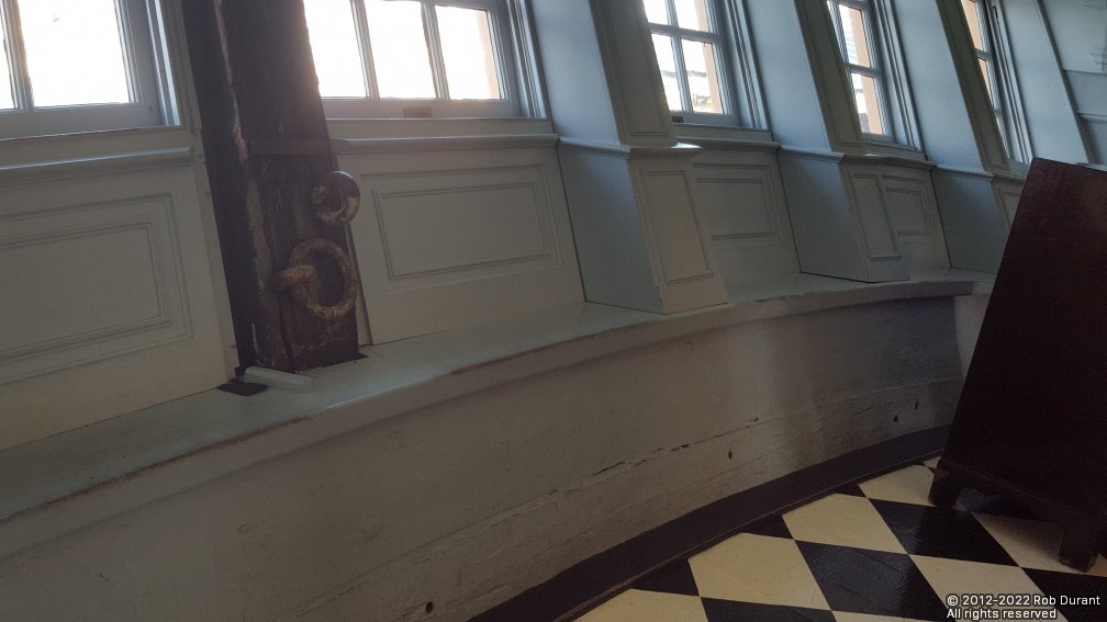
Here's a photo I took in Victory which gives some idea... for some reason I didn't take any wider angle pictures in there...
- thibaultron, mtaylor and starlight
-
3
-
6 hours ago, gak1965 said:
Background movie in the first pic is, of course, The Hunt for Red October. One of several proper choices, I think you will all agree, for ship modeling.
Hear hear
-


Barque Stefano by robdurant - MarisStella - 1:63
in - Kit build logs for subjects built from 1851 - 1900
Posted
Thank you, Rob")
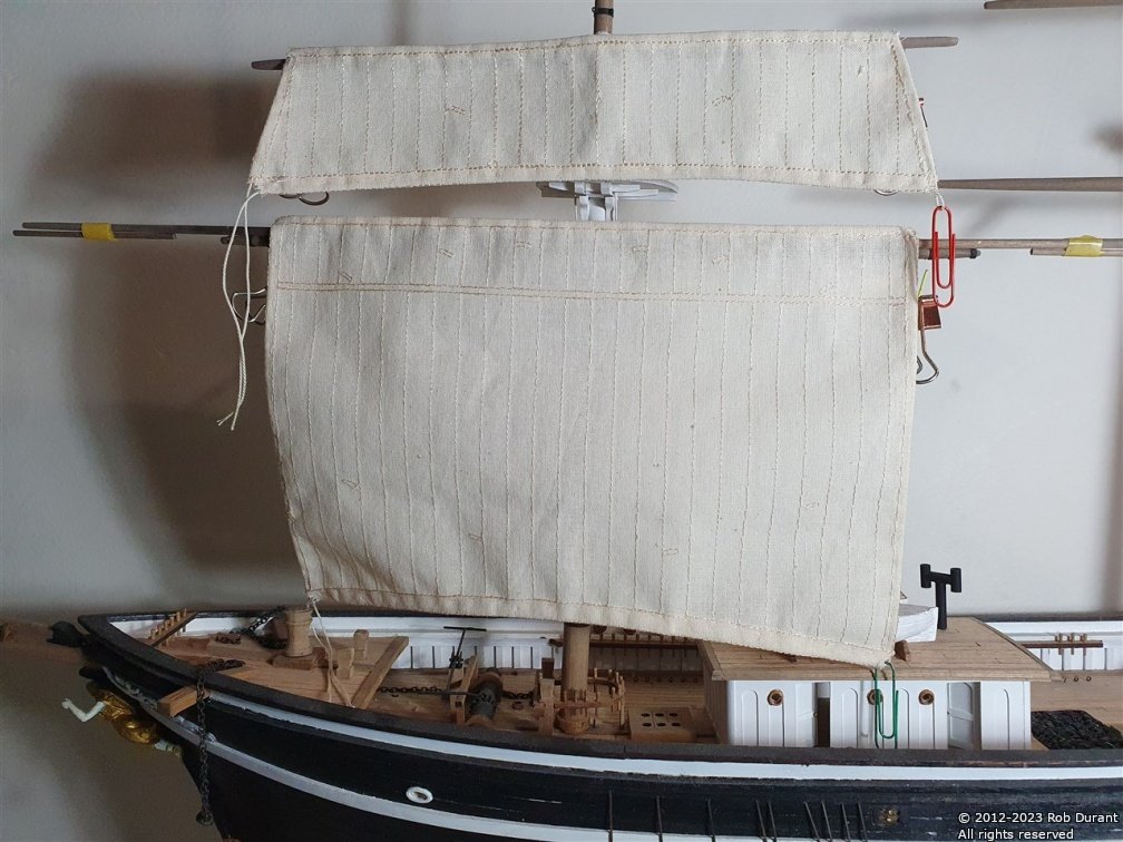
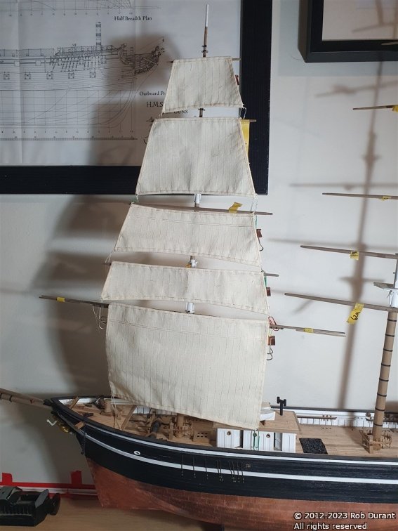
And a couple of studding sails... I've discovered that sewing sails is actually really really relaxing (except for when I'm stabbing myself with dress-making pins!)... I can strongly recommend this as an enjoyable part of making the model. The plans include complex instructions for hemming the corners - due to the relatively coarse nature of the sail cloth, I have found it to be far too apt to fray for this to be possible (there's nothing left to sew that close to the edge of the fabric). Once the hems are done it all becomes much more manageable. Others with more experience of this may have excellent suggestions as to how this can be avoided. But I'm pleased with the results I'm getting, and as always, though I may not be able to reproduce them exactly they plans themselves are works of art, which I shall enjoy long after I've finished this model.
Care has to be taken with the studding sails (which are RH and LH), to ensure the hems are put on the back of the sail, and you don't end up with two RH or two LH! I've avoided this frustration so far... Check twice, sew once, is the order of the day")
Happy building, all.
Rob