


robdurant
-
Posts
801 -
Joined
-
Last visited
Content Type
Profiles
Forums
Gallery
Events
Posts posted by robdurant
-
-
-
Thanks for the likes.
Okay - I took the plunge. The holes for the belaying pins turned out to be a little tight, so i redrilled them out to 1.3mm, and then glued the pin rails onto the strake and the underside of the rail.
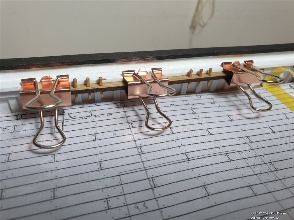
Now I'll leave it overnight and we'll see just how strongly the carpenter's glue has stuck the rails on. The contact area for the glue is pretty big compared to the pieces themselves, so I'm reasonably confident they'll be okay.
If this has worked, then next up will be the eyelets on the rails, deadeyes (which also mount on the rails, and the chainplates.
-
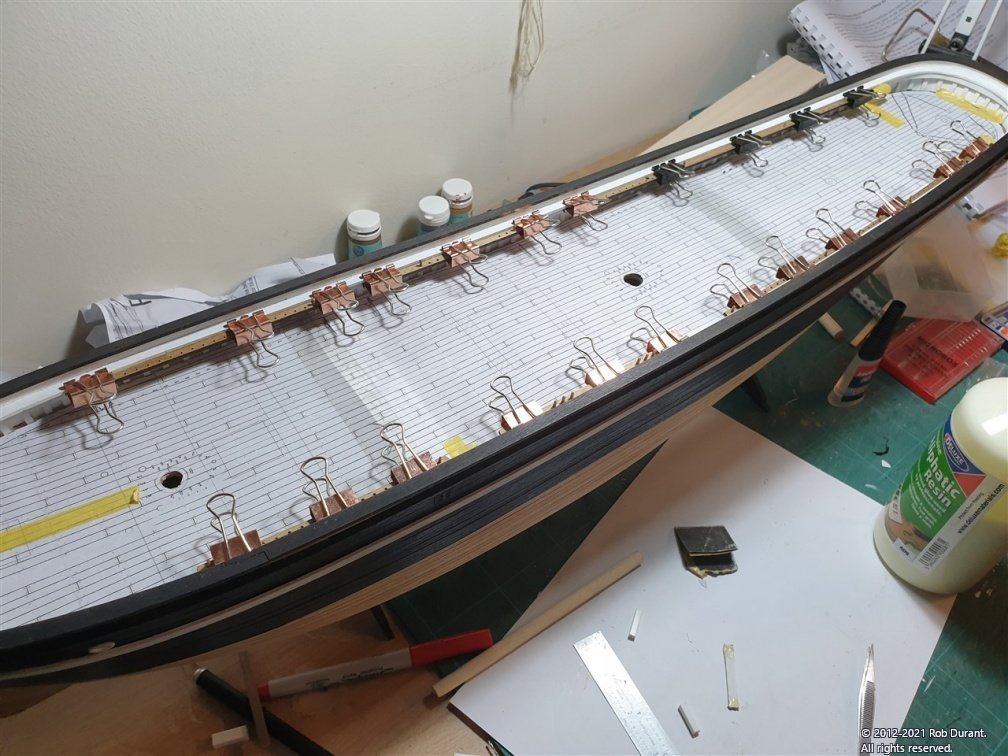
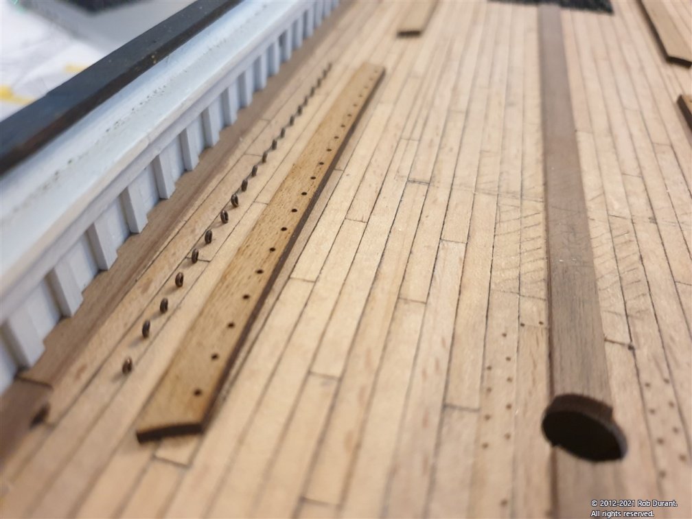
A little update. I realised that once I stuck the pin rails (parts 43) in place, I would restrict access to the deck to put in all the eyelets. So I printed out a scan of the deck plan on plan 3, stuck the parts together, and used it as a template for the holes. The plan was located using the mast holes to ensure the eyelets holes went in the right place.
Some 100 holes later, I began gluing in the eyelets (which are blackened rather than painted) with superglue. This was time-consuming, but after a good few hours, it's done.
There are eyelets included in the kit, but I used some which I already had blackened, and left over from a previous Caldercraft kit. They needed 0.60mm hole.
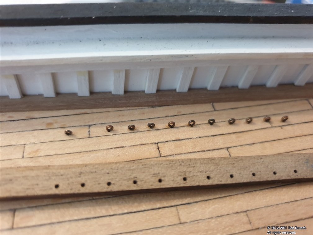
I'm going to replace the belaying pins that are provided with caldercraft ones. Namely, the 9x1.5mm ones, which are longer and thinner, and to my eye somewhat more to scale - I swapped out the HMS Diana ones for these, and was glad I did. These 9x1.5mm pins need a 1.2mm [edit: actually, I opened this up to 1.3mm later] hole, so the pin rails have been drilled out in readiness. In the instructions this is done after the pin rails are glued in place, but I didn't trust myself not to scuff the deck.
Now, I'm just wondering whether to strengthen the bond between the pin rails and the bulwark? I'm just not confident I won't knock it and end with a massive tangle of rigging and no way to get it back in place. I might try and put some pins in to help adhesion.
Hmm... have to think about it. Hopefully I'll be able to get some more done today.
-
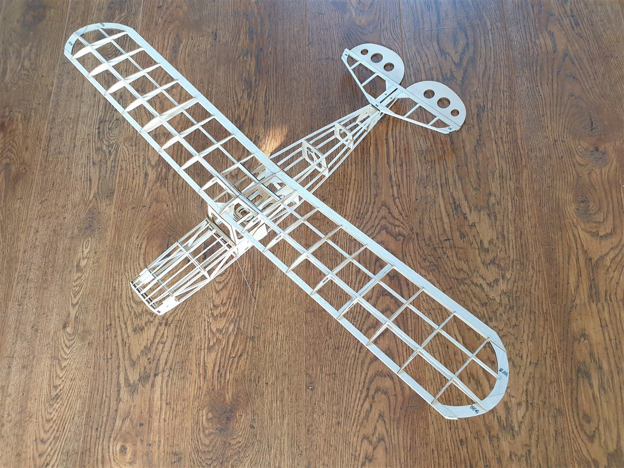
Okay. The plane is all skinned and radio-controlled and ready to go. I'm just waiting for the battery charger
")
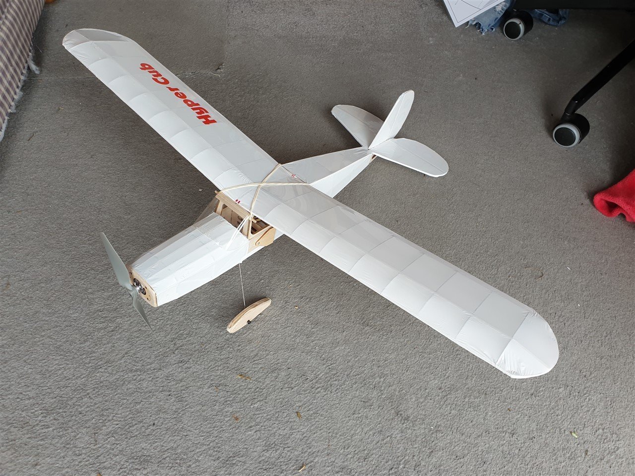
So... time to go back to the bigger project.
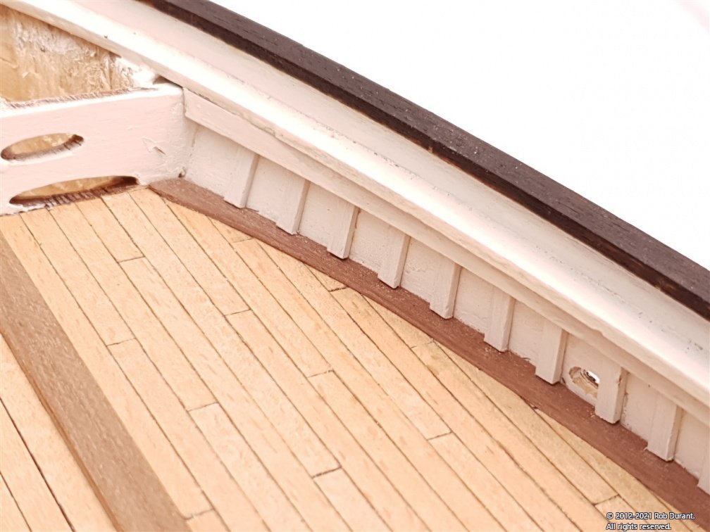
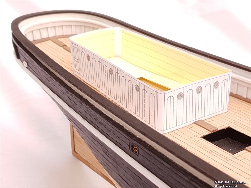
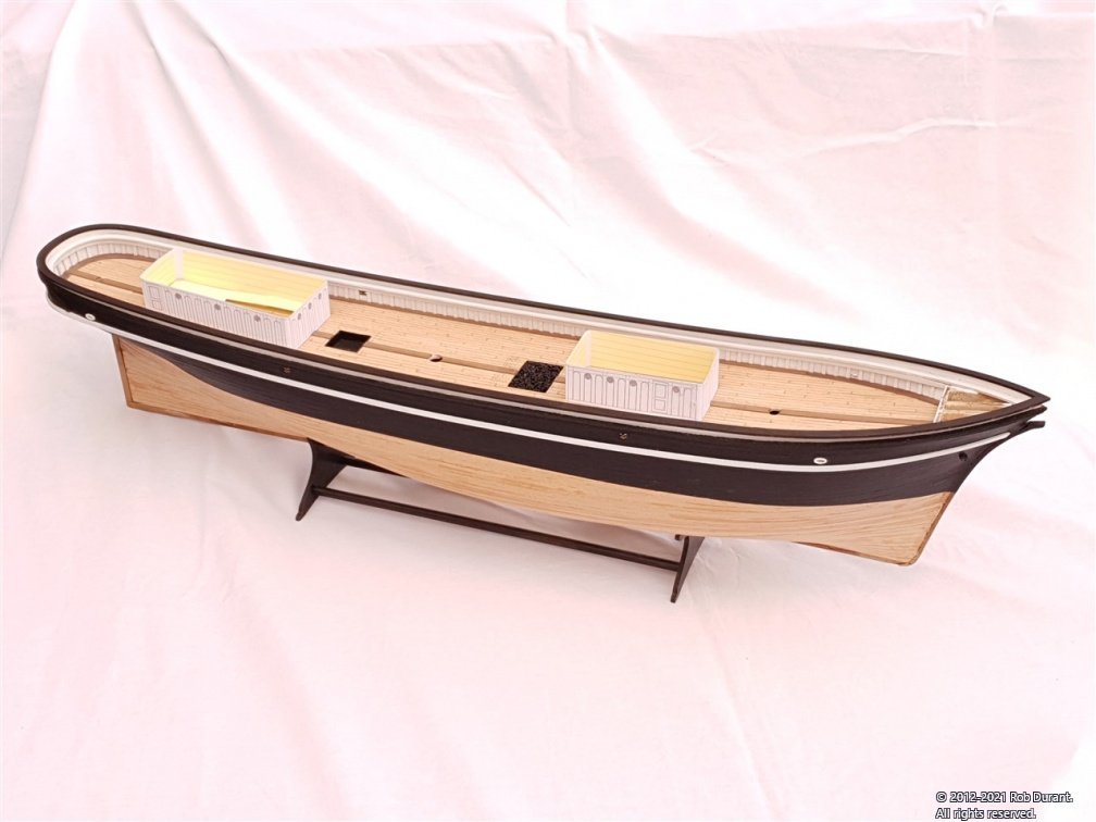
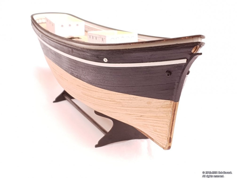
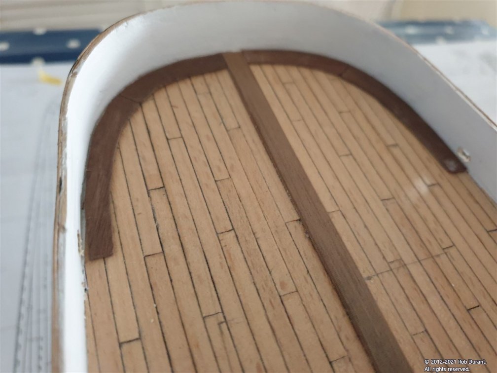
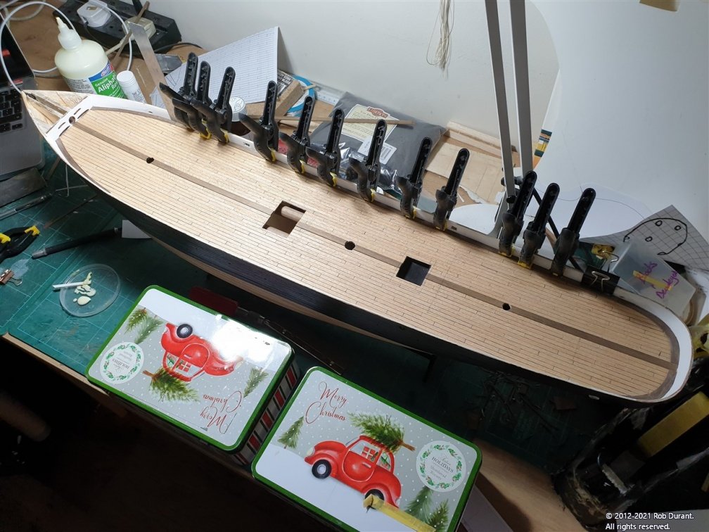
I've ummed and aahed and wondered how to best go about the topgallant bulwarks, and eventually I just had to bite the bullet and get on with it. And it turned out to be not so bad. I used styrene square section as shims on either side, and pre-bent the parts using my rib-bending iron. They were glued in place with carpenter's glue (Alphatic resin), and left overnight to set really solid.
Once in place I painted the inside of the rail white, and tidied up a bit before the topgallant bulwark rail was stuck on. This is made up of laser-cut parts from the 2mm walnut, and as with the main rail, it was the perfect size and shape. So that was a relief. I glued it all together using masking tape to hold the parts together while they stuck, on the desk, and then glued the whole thing in place in one go. This allowed me to get a nice sweeping curve from front to back. Then I gave myself a big pat on the back, and THEN I realised it was glued too far inboard. So I've just unglued the sides, and restuck them further outboard, so the top rail ends at the same point as the main rail, as per the plans.
The thing that made me see my mistake was looking at the plans and seeing that the deadeyes are going to go on the main rail, and if the top gallant rail is too far inboard it leaves no room for them. I suspect they're going to be somewhat challenging to rig anyway, so I'm leaving myself as much room as possible to ease the process. It's only a matter of 2 - 3mm but something tells me I would have been rueing the day I chose not to bother moving it.
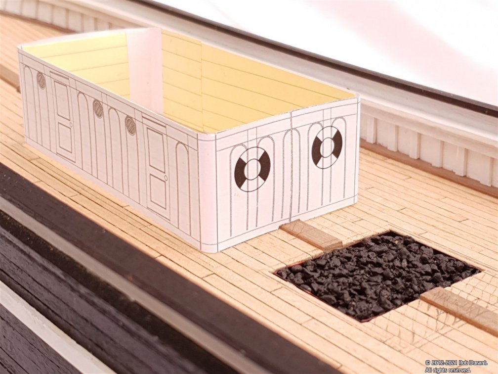
Anyway - here's a photo I took before I realised the rail was too far inboard.
Also in some of these photos are the mockups for the photo-etch cabins I want to put onto this model. Currently they're a bit heath-robinson, but they prove the concept, I think.
Happy building
-
Very nice crisp work on that companionway. Good to see HMS Jason moving forward again. And a good idea to fit that deck in parts. I didn't and ended up with a slight wave along the quarterdeck on the starboard side which I'll always know is there even if no-one else notices.
-
Okay - so updates here have been a little less frequent, as I got distracted helping my son get stuck into warhammer and with those flying things - a refreshing change for a little, and a work in progress...
I'll be back onto Stefano soon
- Beef Wellington and egkb
-
 2
2
-
Amazing! All the very best to you and your wife, Chris and every success to Vanguard Models.
- Canute, mtaylor, Ryland Craze and 1 other
-
4
-
That's a very neat looking repair that looks like a great foundation for the copper tiling.
Unicorn's a fascinating vessel... I hadn't realised the roof was so old... I hope, Dunnock, you won't mind me linking to this article recently put on the BBC news website that gives a little more information from the team involved in her care...
https://www.bbc.co.uk/news/uk-scotland-tayside-central-56818539
If anyone has some nice oak they don't need, they'd be interested
Hopefully they'll manage to get her into a dry dock sooner rather than later.
Rob
-
3 hours ago, rwiederrich said:
what kind of wood filler did you use
Hi Rob (@rwiederrich),
Not too late at all... I discovered this wood filler, which I find a massive improvement over normal DIY filler. It's much more sturdy once it dries, almost odourless, doesn't seem to shrink at all, and easy to sand to a nice finish. It's also available in much larger quantities than most hobby fillers, so it's much more cost effective for smoothing a whole hull.
This (fairly small) pot was more than enough for the whole hull (and a few diy jobs around the house, too!)... I'd recommend it over the tube of the same product, which I found dried out very quickly, and got to the point where I couldn't get any more out of the tube.
Hope that's helpful.
-
-
As a little side note for anyone following in my footsteps, the rubbing strake literally runs along the top of the water run off holes in the side of the hull, so it's worth taking extra time to make sure those go in the right place. Thankfully they proved to be right for me. At least for the port side!
-
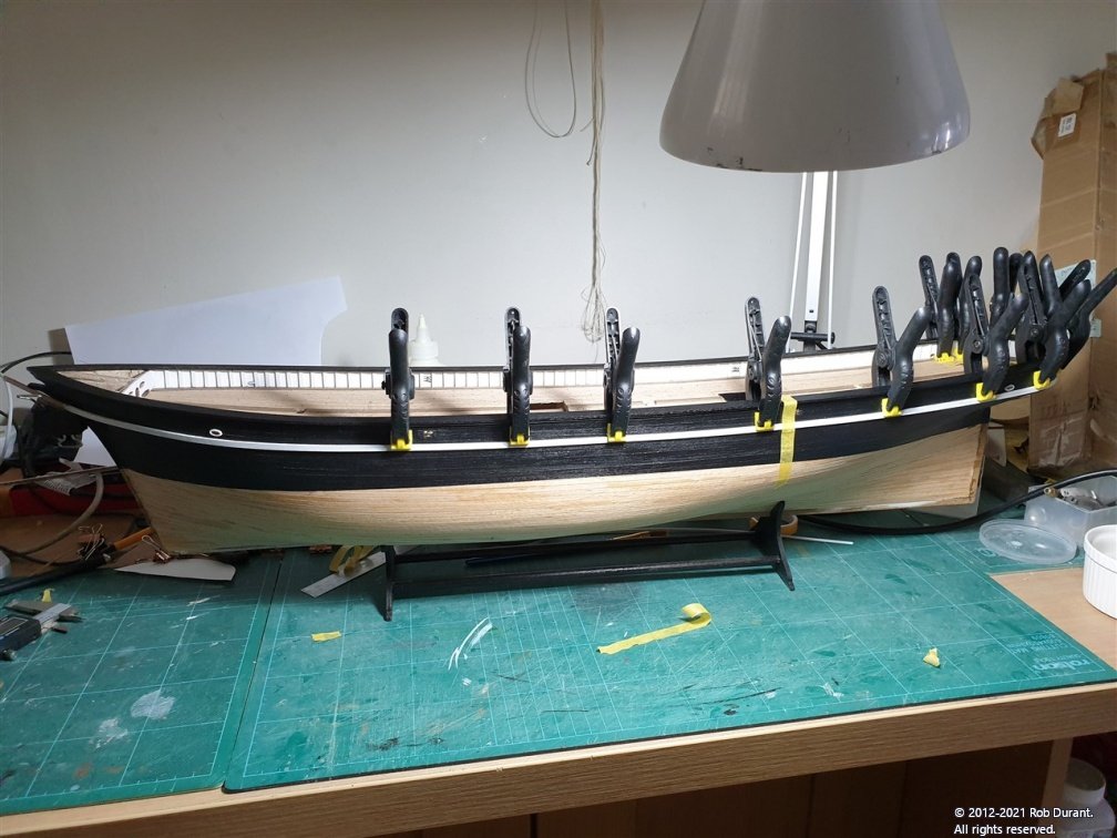
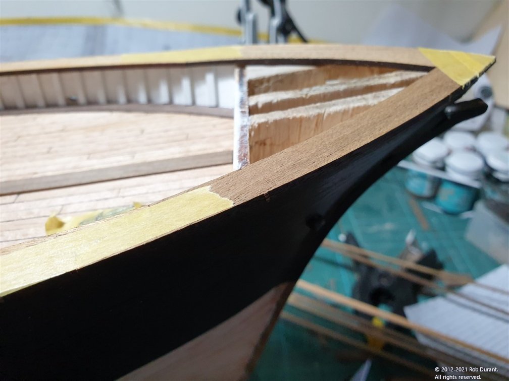
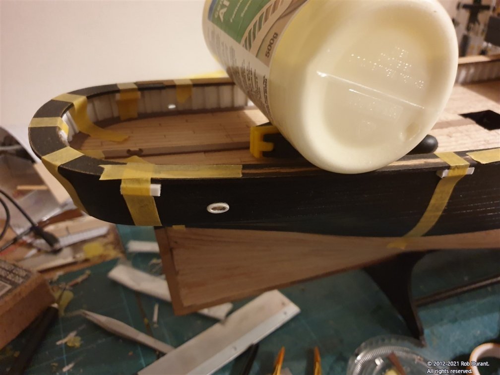
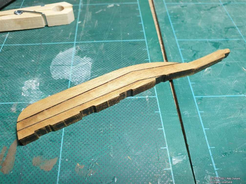
I've been pondering for a while (analysis paralysis!) how to get the rubbing strake round the stern without it standing proud, and with enough contact for it to glue well... Planking the hull proved that trying to find any shortcuts here would cause pain down the road... so... here's my attempt.
It's 4x1.5mm walnut, and pretty sturdy, so I thought why not bend it to shape, then bend another plank to width to go inside round the stern, and then sand the taper caused by the counter into that double width so it ends up single-width by shaped...
Something like this...
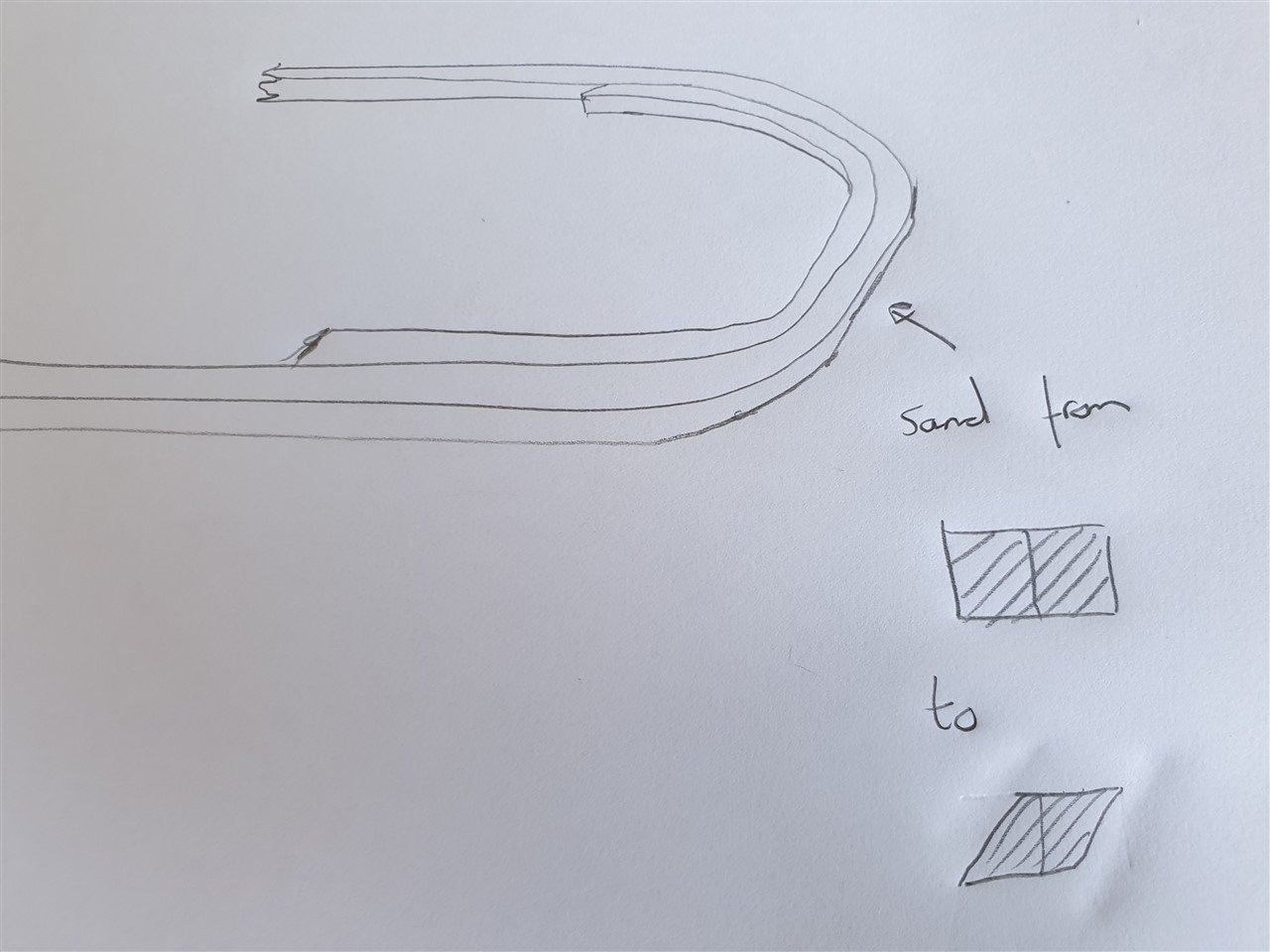
Clearly that cross-section would need to be tapered as it went round to the sides.
I was concerned that it would be hard to get that inner-taper right, so I used a plank with less height on the inside at the bottom, to make tapering easier. (1.5x1.5mm)
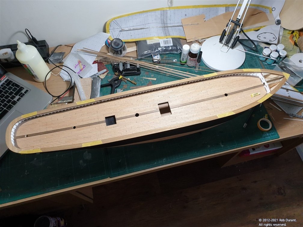
Some pictures follow...
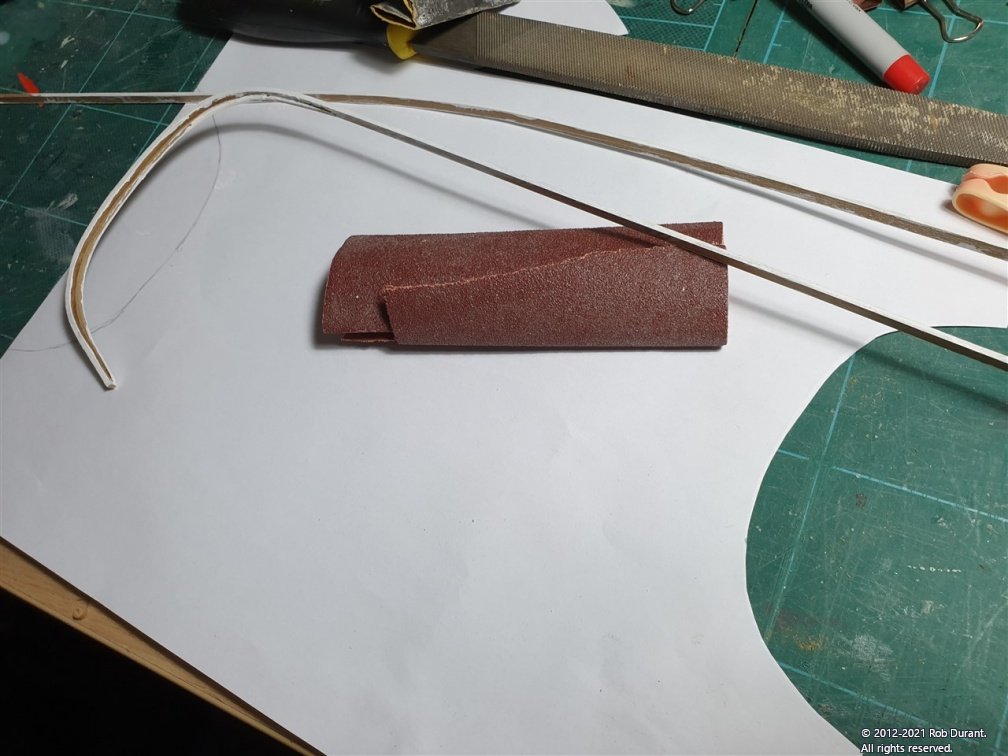
1. Rough shaping the parts...
Painting before gluing in place...
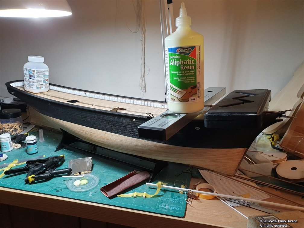
3. Gluing in place with carpenter's glue... (and checking the gap is 18mm from the top of the main rail, to the top of the rubbing strake)
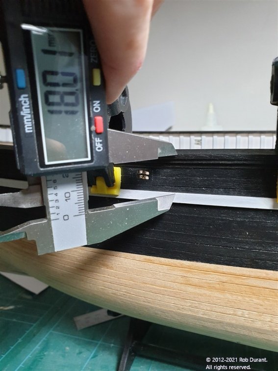
And checking that the decoration would fit at the bow...
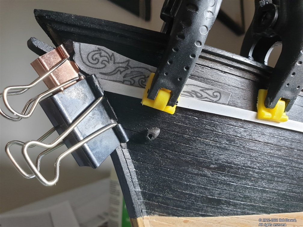
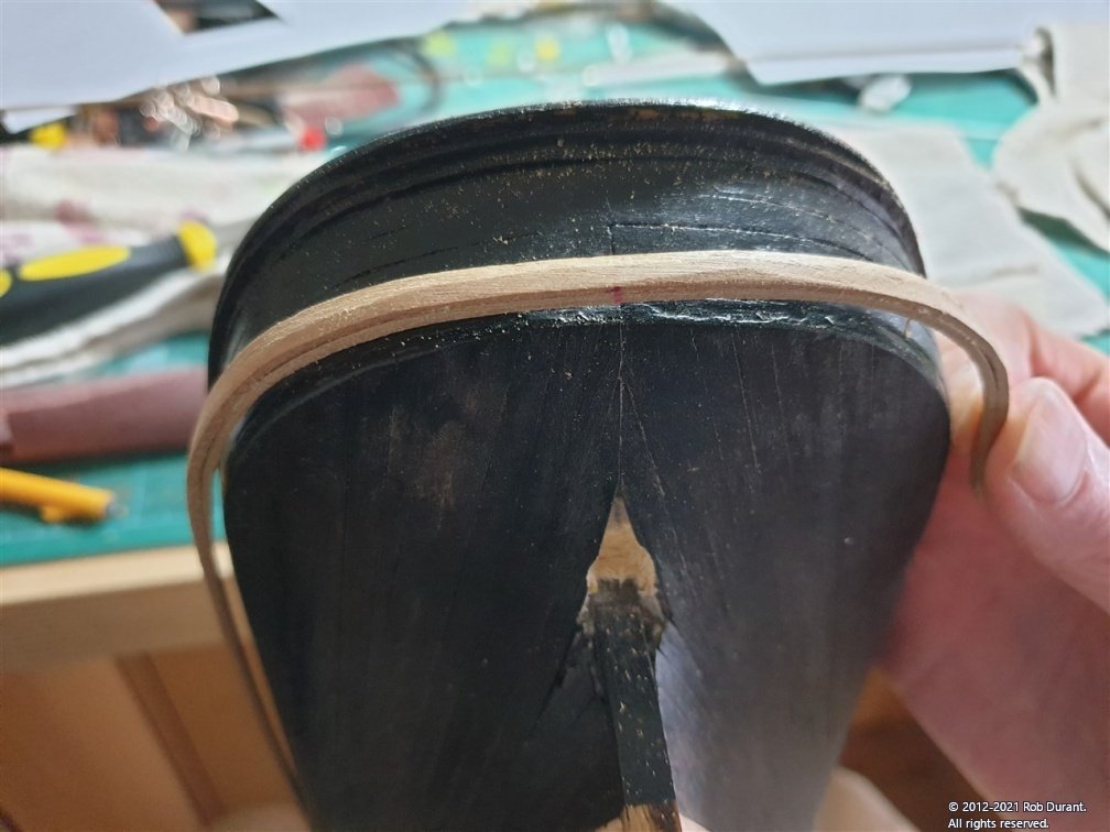
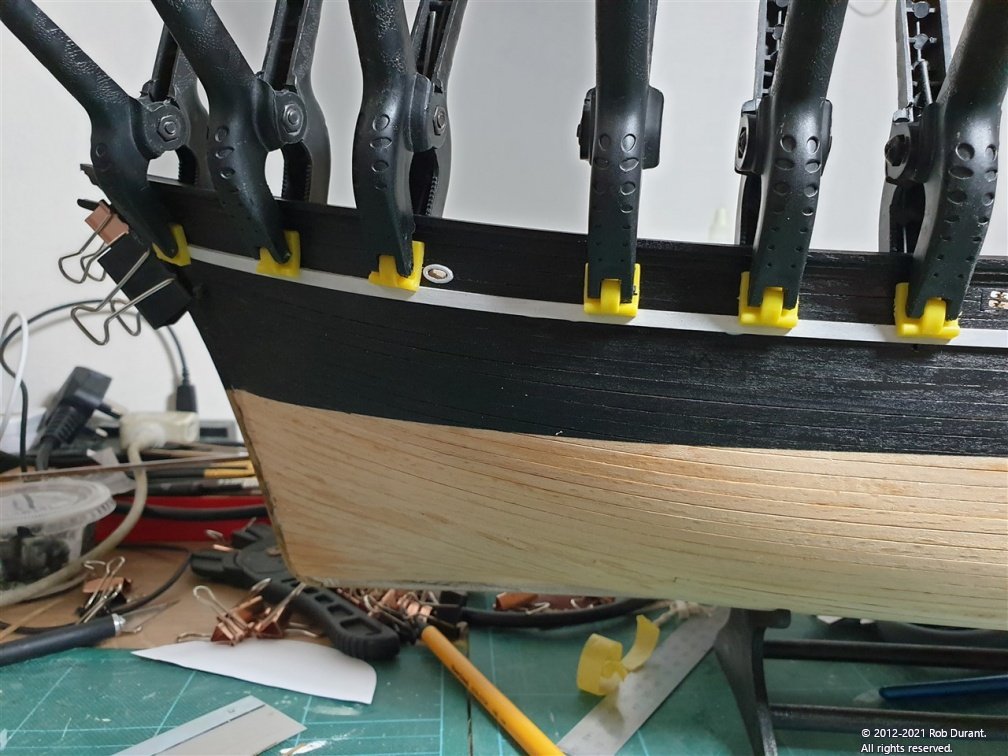
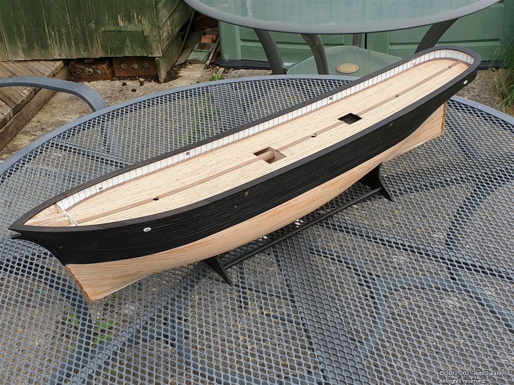
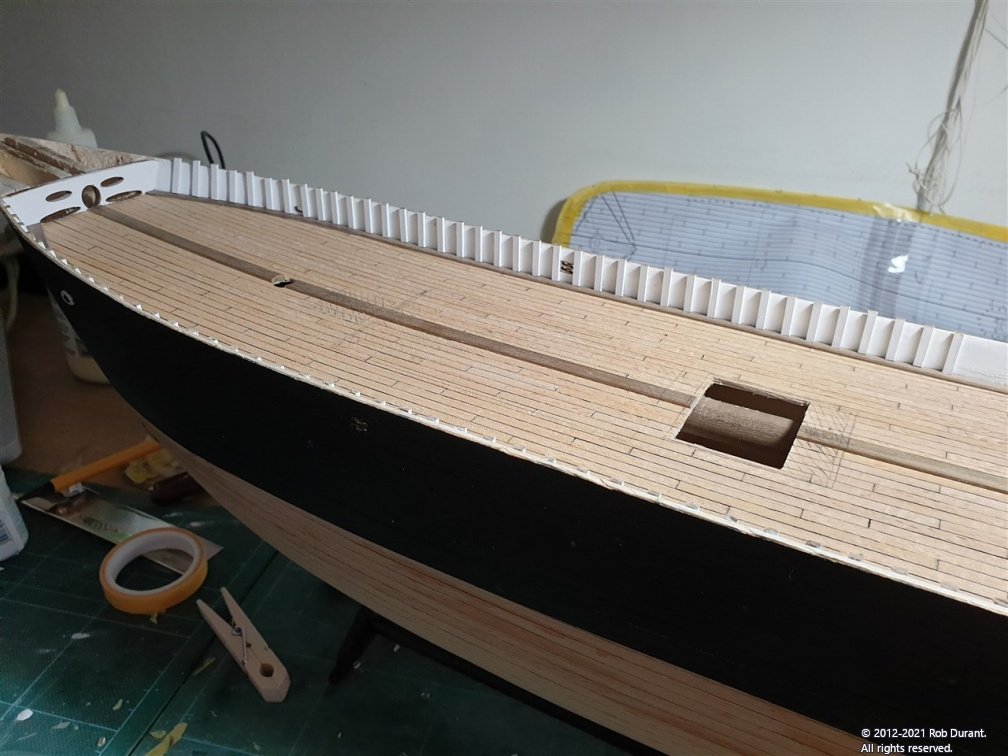
4. And a few photos of the result...
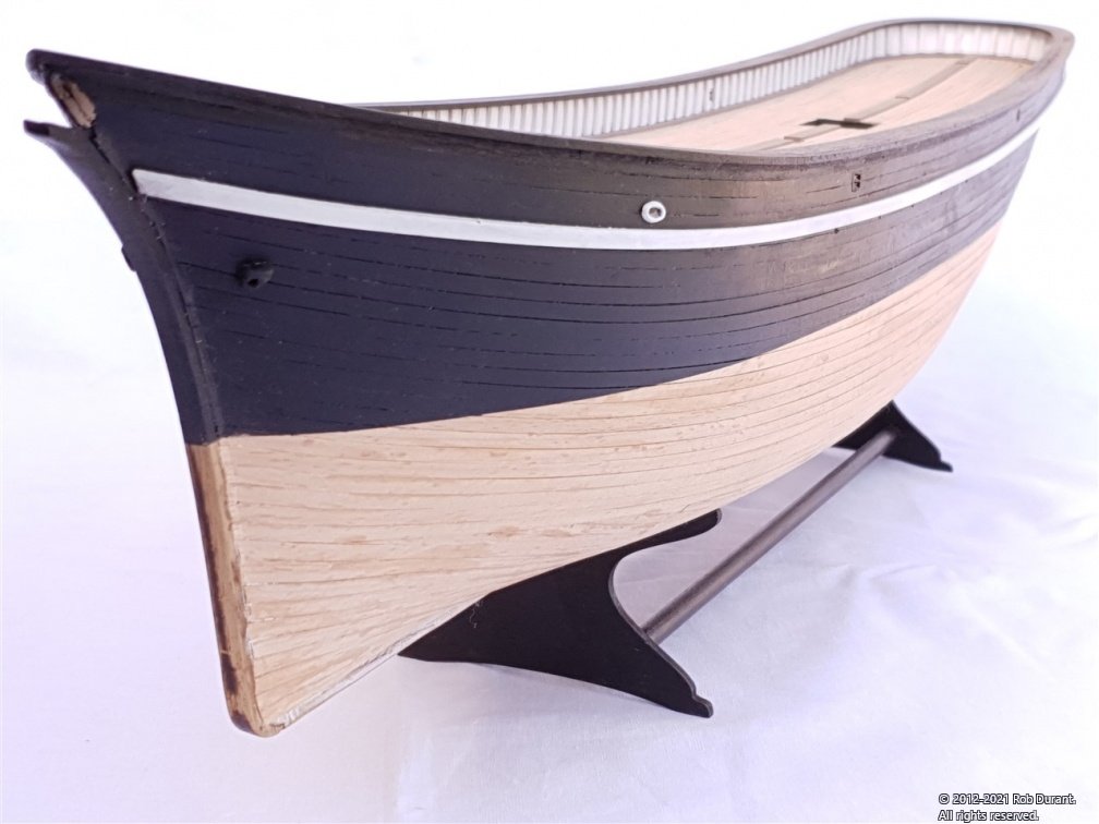
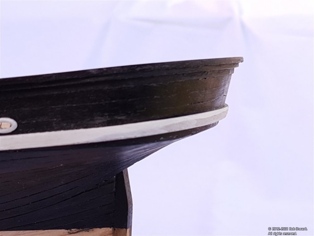
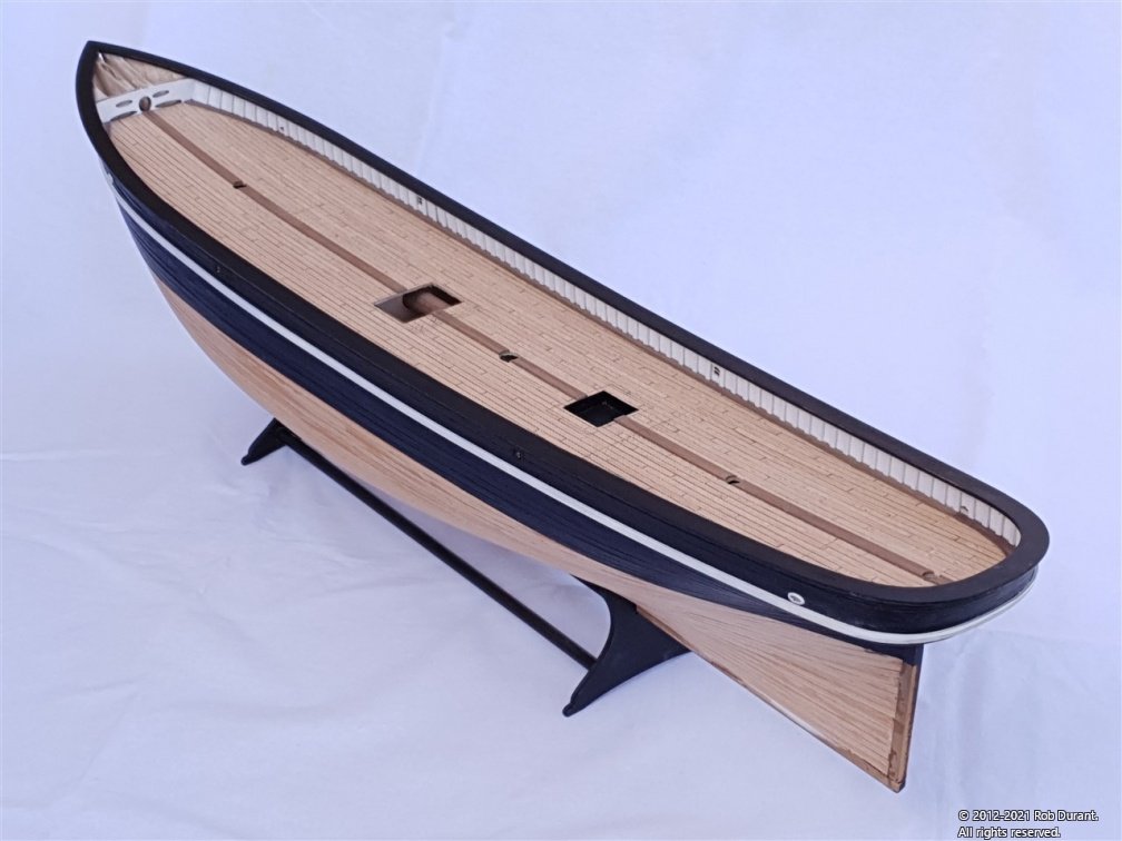
Because the stern piece goes right round, the other side should be much easier by comparison.
Anyway - thanks for looking in, and happy building
Rob
-
-
On 5/27/2021 at 8:16 PM, BranPie said:
Might be a little update...but I'm thinking that wasn't a little bit of work 😲
Hi @BranPie - you're right. This took longer than I was expecting. It's the first time I've done top timbers like this, and it takes perseverance... But no more than a deck full of guns, or a shroud full of ratlines
") The main challenge is to neatly cut the walnut to the correct angle for the deck both at the bottom and the top without knocking the corner off. I did this by using a scalpel to cut through the grain on the far side to prevent it splitting out, but it doesn't make it more time-consuming.
The main challenge is to neatly cut the walnut to the correct angle for the deck both at the bottom and the top without knocking the corner off. I did this by using a scalpel to cut through the grain on the far side to prevent it splitting out, but it doesn't make it more time-consuming.
Once they were all cut down to size carefully, with an xacto saw, I added the pre-cut parts that form the rail. These parts fitted beautifully. No adjustments were necessary - just care to ensure they were glued with a 4mm gap on either side of the hull. This was achieved using plasticard as packing. Weight was applied to get the parts to follow the curve of the freeboard.
I pre-painted these parts, leaving a small gap on the under-side where it fixes to the freeboard. I didn't fancy trying to cut the paint in along the toptimbers!
Here are a few photos of the process.
First, the parts were tacked together at the joints with masking tape, and laid on top of the hull to check the layout. The parts were left in place while the individual parts were glued to ensure they would eventually fit.
Then the parts were painted, and glued in place one by one, with the packing around the sides to ensure they were lined up with the freeboard...
Because the walnut has quite a lot of grain, the parts were sanded and then painted again a few times to smooth them out, and to knock off the very sharp edges. This is especially important where the end grain meets the edge. Sand with the grain, not against it... otherwise it could splinter out.
I worked from the stern towards the bow.
And here's the end result...
There's a little touching up to do, but I'm very pleased with how it's come together... The contrast between the white and black is very striking, along with the tanganyika and walnut of the deck. Onwards and upwards!
Rob
- rybakov, Beef Wellington, egkb and 9 others
-
12
-
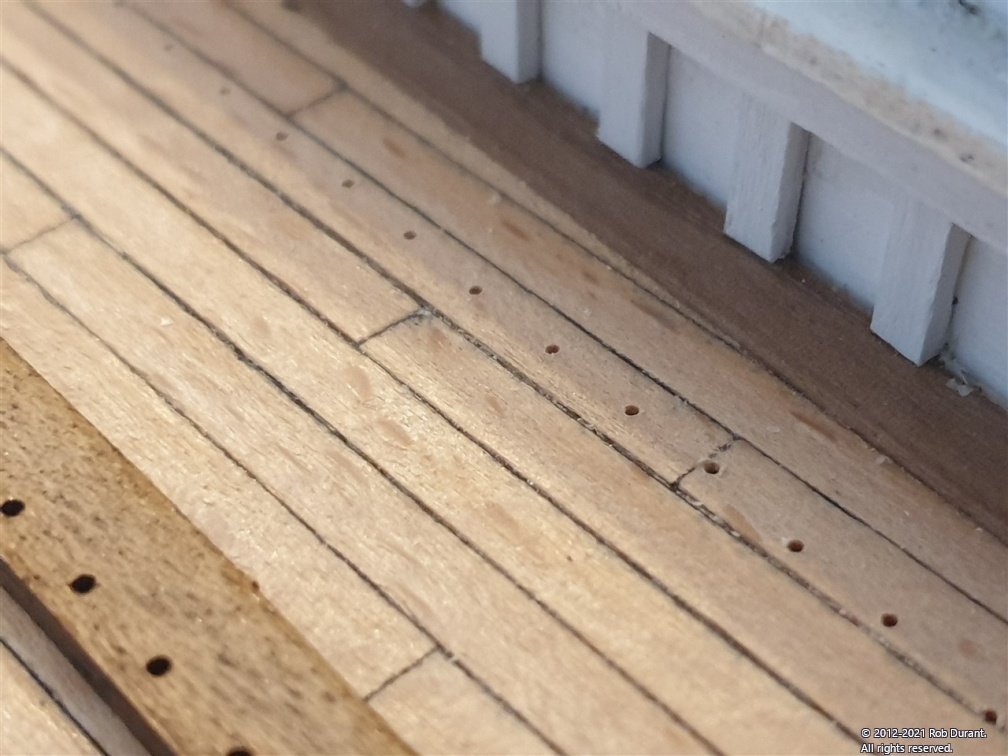
Hi all,
A little update. I've cut and glued all the uprights (top timbers?) along the edges of the deck (the bulwarks). About 160 of them in total ... all checked with a spirit level to try and get them vertical to the waterline. Now I just need to finish cutting them back to the tops of the bulwarks.
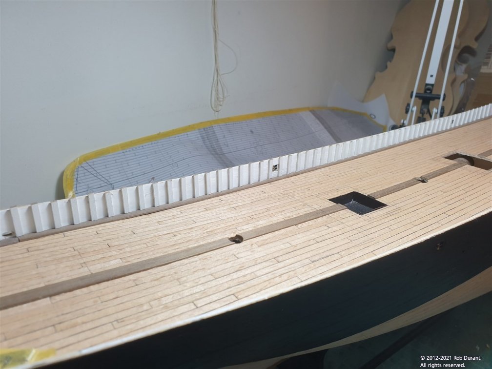
They were slightly adjusted where necessary to clear the holes that come through the bulwarks.
- egkb, GrandpaPhil, BobG and 5 others
-
8
-
-
On 5/19/2021 at 3:17 PM, Mike_H said:
Anyone have a problem with drag-and-drop occasionally not working? I'm using an old iMac, and quite often I can just drag photos from Photos to the panel in a comments window on MSW. But then in stops working. If I restart t he computer it fixes itself for a while. Simply quitting either Photos or browser (I've tried Safari, Firefox and Chrome) doesn't fix it.
You may find it's easier just to use the "choose files..." button underneath the post editor and manually select the pictures from your filesystem instead of dragging and dropping straight in. You would need to export them from iPhoto first, but it's probably a more robust method than dragging and dropping, (which relies on iPhoto working out it needs to export the photos, and then passing that information through the clipboard to the browser, which then imports them).
Your problem could be caused by any number of issues (spare physical memory / page file / processor capacity on the computer to process what's happening, app incompatibility, application race condition, etc...), but as I said, the easiest thing is to take the issue out of the computer's hands and just use a more robust step-by-step method.
If you want it to not be irksome, you could perhaps write an automator script that did these steps. That may depend on which version of OS X / OS 9 you're using, and how comfortable you are with Automator.
Hope that's helpful.
Rob
-
Oh yes, and another note that may be of help to other builders of Stefano.
In the instructions, when you get to the point you're installing the rosettes, there are rosettes for the hawse-pipes, but then another rosette is mentioned for the anchor opening... that in fact is the rudder opening rosette. It's 1mm ply, and marked as no. 32 and it forms a surround for the rudder post hole under the transom. You can see it in place on plan sheets 2 and 3.
Happy building.
Rob
-
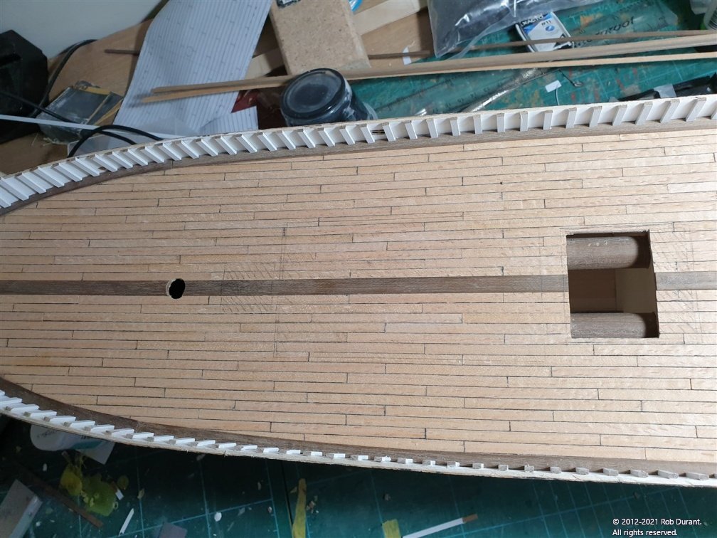
Hi all,
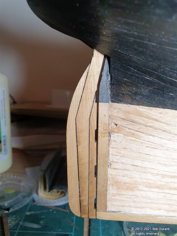
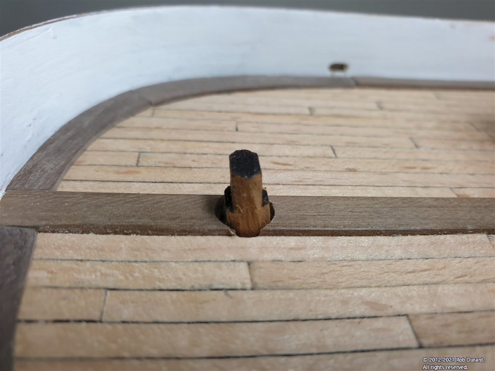
Thanks for the likes. I've made a little progress by drilling out the (almost) vertical hole through the transom for the rudder post. In retrospect, perhaps I should have done this before I glued on the stern post, as it would have made for much easier access to drill from below, but the stern post was glued in place, so instead, I measured up where the hole should start, and then used a 1.5mm drill glued inside some 2mm plastic tube to make the initial hole. The plastic tube allowed me to align the drill by running the tube along the stern post, thus creating the right angle for the hole. The photo below shows that the stern post steps in towards the top (as does the rudder) so by putting the 1.5mm hole vertically above the top of the aft extent of the stern post, the hole ends up in the right position. Hopefully that makes sense... I neglected to take any photos of this stage.
With careful checking at regular intervals, the hole eventually made it's way through the king plank on the deck, and it was then opened up using a series of drills from above (being careful not to scratch or dent the stern post as the drills made their way through to the other side) until the hole was approx 7.5mm. At each step, the hole was checked to make sure it remained central to the king plank. (As it turns out this was approx 1mm to starboard of where it should be, but I'd rather shape the rudder post so that it looks central than have the hole off-centre - this won't be a working model after all, so I can cheat
)
Once opened up, the rudder was constructed from it's laser-cut parts, and with some rough shaping of the rudder post it was test fitted. The rudder post fits beautifully, with a nice small gap between the sternpost and the rudder (it had dropped away from the hull a little when I took the photo below, but it does sit closer). I'll bevel the fore edge of the rudder and perhaps taper it towards it's aft-end before finally fitting, the top of the rudder post will need to be shaped for the tiller, and there'll be plenty of work to do to get it coppered, etc... before it gets fitted, but I was keen to ensure it would work before I went too much further.
Thanks for looking in.
Rob
- dunnock, ccoyle, GrandpaPhil and 3 others
-
6
-
-
Hi all,
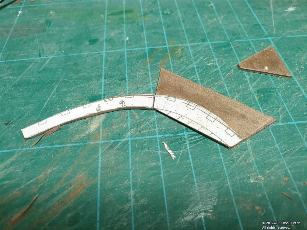
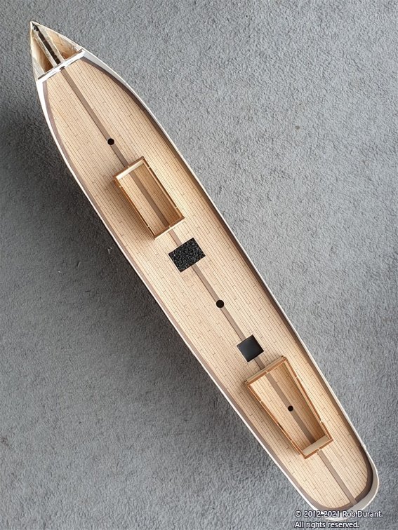
A little progress to report. I finally bit the bullet and - using a sheet of 1mm walnut from Cornwall Model Boats - for the curved sections, I made up the parts that edge the deck (the "covers" as they're described in the instructions).
It took a few attempts, but eventually I got some neat parts cut out and shaped for the stern and bow, and the centre was 1x5mm walnut. I used left over stock I had lying around, but that doesn't mean it's not in the kit - it just means it came to hand more easily, and I'm lazy by nature.
The process for the stern and bow sections went something like this.
Scan the top-down plan on Sheet 3 that shows the deck edge.
Print out the plan to 100% size.
Cut out, and modify the shape at the stern and bow to fit the model itself.
Mark out some sections so that the grain roughly follows the length of the pieces being cut out...
Cut out the sections and pritt stick to the walnut sheet (noting the direction of grain, so it runs along the piece)
Cut out the sections carefully to shape and then steam the pritt stick'ed patterns off the wood by holding with plyers over a boiling kettle for a few seconds.
Trial fit, sand and trial fit again until it's ready.
Here are a few pictures of that process and the results...
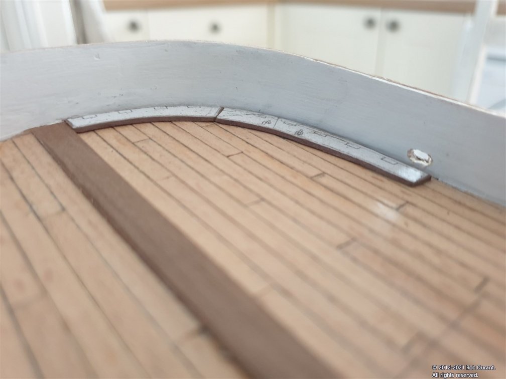
Having glued these parts down with carpenters' glue the gaps were then filled in with the 1x5mm strip.
Right... happy building to you all
More soon.
Rob
- GrandpaPhil, egkb, Roger Pellett and 4 others
-
7
-
My order was less than £135 so it didn't qualify for customs tax... at least that's my understanding and I didn't get asked to pay any extra, where I have in the past on larger orders. Don't take my word for it tho. You can check out the regs here...
https://www.gov.uk/goods-sent-from-abroad/tax-and-duty
I guess if you got all those.blocks you may end up paying tax to import them. I did on the gun carriages I bought from Syren. As long as you factor it in then it isn't a nasty surprise
-
-

HMS Jason by Beef Wellington - Caldercraft - 1:64 - Artois-class frigate modified from HMS Diana 1794
in - Kit build logs for subjects built from 1751 - 1800
Posted
Great work Jason. I'm sure you'll be really pleased you tapered the planks. My approach was a little less precise but still it makes a nice contrast to the straight planking runs on the gun deck. As a thought you may want to put some of the planks down then reassess the widths to make fine adjustments in case laying the planks introduced some drift? But your planking is so precise I'm sure you'll be fine.
My digital calipers are the tool I never put away on my build desk. Especially useful when you need to work put which drill bit you need (and what order they go back in the box when you accidentally drop them!).
Looking forward to seeing this deck come together.
Rob