robdurant
-
Posts
843 -
Joined
-
Last visited
Content Type
Profiles
Forums
Gallery
Events
Everything posted by robdurant
-
 Here's a screenshot of the file size estimate in action... I've highlighted the estimate. It updates automatically whenever you slide the slider.
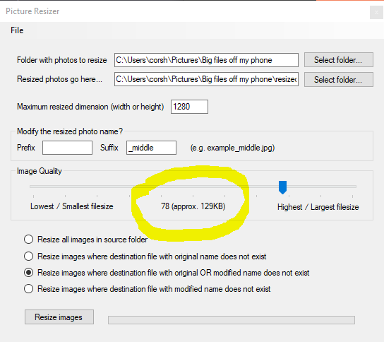
-
Okay - I've just uploaded v1.0.1. It adds a filesize estimate to the quality slider as demonstrated in the video below. If you've already specified a directory for pictures you want to size, the application tests the resizing of one of those images (the first it finds) to find the file-size estimate. Otherwise it uses a temporary image I provided for the application. It won't show an estimate until you've provided a resizing dimension, but the estimate is based on that rescaling size. It is still an estimate as far as any other images you will resize, but hopefully enough to give a helpful idea: The uploaded application file is on https://durant.biz/pictureresizer/ as before. Thanks for the feedback Rob
-
I agree. Because JPEG is compressed each image will be a different size and depending on how complex the image is (how much detail must be rendered) the file size can vary quite considerably. But I could certainly provide an estimate. Or perhaps even a feature to resize to a maximum dimension or a maximum filesize (whichever was smaller). This could take a little more time for the computer to process but would certainly be possible.
-
She's coming on nicely. And I'm sure you're right about who notices what... we're often our own worst critics. I'm afraid I can't offer much help with the running rigging but you seem to be making good decisions so far. You'll be on the home strait before you know it.
- 39 replies
-
- 1
-

-
- billing boats
- danmark
- (and 1 more)
-
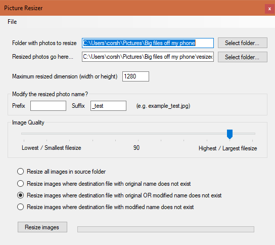
Hi, Just a quick note to say I've finished writing some documentation that basically says what I say on the video, but puts it down on paper for those who prefer to read than watch. You may find that the video helps fill in any gaps where I haven't described it very well on paper. Let me know. In other news, I realised that I hadn't implemented anything to make it possible to specify the compression of the outputted image. That's done now, so when you install the application you'll see a new slider - slide it to the right for less compressed, better quality, bigger filesizes... and to the left for more compressed, lower quality, smaller filesizes... I'd recommend around 90 for photos that look almost uncompressed to the naked eye, but take up 10x less space on your disk than the photos at compression level 100. The number in the middle shows the number you've selected and updates as you move the slider. PictureResizer.Documentation.20201121.pdf
-
Hi all, Moderators : Apologies if I've put this in the wrong place... please do move it. I'm aware from watching the forums over a little while that uploading pictures to the forum can be a bit confusing and stressful, especially when it comes to why pictures that look fine are rotated wrong when they arrive on the website. It's confusing for us, but it also results in a bunch of questions to the moderators and admins on this site, which are hard to answer from afar. To try and help with this, I've programmed an application for Windows 10 that takes images in one folder and puts them into another having resized and hardwired the rotation. If you then put more photos into the source folder, it'll just resize the new ones that haven't been resized before. You get to decide the maximum dimension of the resized image, and modify the filename for clarity. You can also set the quality of the new images to alter the amount of space the files created take up on your hard drive, and how much time they take to upload / download (this last piece of functionality was added after the video below was made. Anyway - this YouTube video gives you an idea of what I've programmed... it describes installation and usage step by step. I would STRONGLY recommend watching the video before you download the application and try it out. (It'll help me if I don't get asked to answer questions that are already answered in the video) If it's helpful to you, you can find the video, and download link along with the documentation I'm half way through writing at the link below: Please be aware - I've programmed this in my spare time... so whilst I use it myself, and it seems reliable, I can't be 100% sure it doesn't contain bugs. Please don't use it if you aren't happy to take responsibility for what it does to your computer. I can't take responsibility for loss of data / time or damage incurred as a result of using it. Nor can I offer 24/7 support (because it's just me). So - if you're happy to have a go, and try it out, then go ahead. You will be asked to agree to this when you install it. Download link and documentation: https://www.durant.biz/pictureresizer/ Hope it blesses you. Let me know how you get on. Rob Durant
- 37 replies
-
- 13
-

-
-
I'm truly sorry to hear this. I hope you're getting a lot of enjoyment out of the build in amidst the fine detail challenges and added frustrations... I'm certainly enjoying looking over your shoulder as the ship progresses.
-
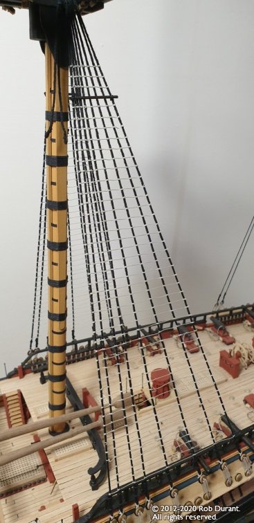
Those stays look nice and evenly tensioned without pulling the mast out of true. I'm just getting to that stage on my build and I always find that stage a little daunting. More shrouds to put up first for me, though.
- 39 replies
-
- 1
-
-
- billing boats
- danmark
- (and 1 more)
-
Glad that plan was useful. Those tops look great. When I came to put the futtock shroud in I found that the extra height the planking added meant that I couldn't use the amati deadeye strops I bought for the purpose but thread knotted above and below the top has proved a neat and effective substitute. I've taken some photos and I'll try and put up a post on my progress tomorrow on my log. You going to zip past me at this rate
-
This looks fascinating - hope you don't mind if I follow along.
-
Wow that's a beautiful job and her lines are really shown to great effect in those photos.
-
And with that tricky step done, that feeling of satisfaction should only grow as you progress! Great start, Tim. She'll do her captain proud.
- 164 replies
-
- 1
-
-
- fly
- Victory Models
- (and 4 more)
-
I tend to put a little on a scrap of card and use a cocktail stick to pick up a little and move it to the joint. If it's thin ca glue, capillary action will draw the glue in between parts. The angle of the cocktail stick can change the size of the drop of glue on the end... then it's just experience and getting a feel for it. There are plenty on this forum who are far better at this than me though so there may be better advice forthcoming
-
Hi Tim, Hope you don't mind me following along Fly really is a handsome ship, and I'm sure you'll do a great job. It doesn't feel like two minutes since I built my first wooden model ship, and yet somehow six years and four models have come and gone! I couldn't have done it without the support and encouragement of the guys on this forum, so if I can pay it back at all and help you out in any way, let me know! Rob
- 164 replies
-
- 2
-
-
- fly
- Victory Models
- (and 4 more)
-
That's looking really great Peter. The square section of the mast looks very crisp.
-
Hi George. I've only used the 1:48 stanchions but I would imagine they scale... so the 1:48 ones have 22mm showing above the deck, so that would make the 1:72 ones 14.6mm? Do check they are even spacing... perhaps this link might be better https://fleetscale.com/store/gb/etched-fittings-/337-1-72nd-rn-3-bar-stanchion-set-etched-brass.html?search_query=stanchions+&results=25 Rob
-
Hi. I've really enjoyed reading through your log - Your model is coming together brilliantly. Your mention of the lack of stanchions made me wonder whether the following might suit (1:72 rather than 1:75, but perhaps close enough?): https://fleetscale.com/store/gb/etched-fittings-/898-original-jrh-560-stanchions-x-200-172.html?search_query=stanchions+&results=25 (I have no connection with this company - I've just used them for fittings on models I've built in the past)
-
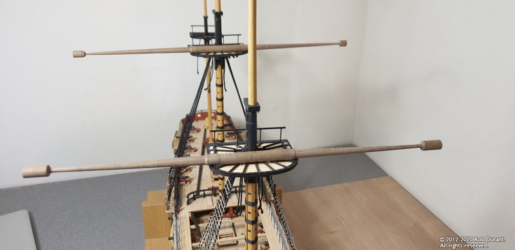
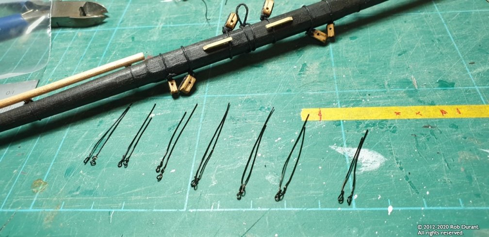
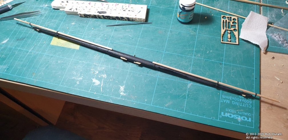
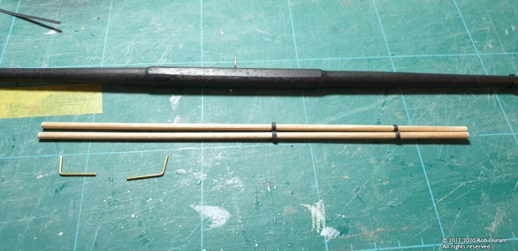
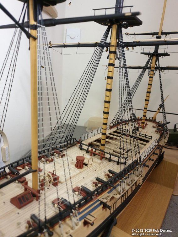
Thanks Jason, and to everyone who's spurred this project on with likes and encouragement! The boats have taken a bit of a pause, but I do have a little progress to report. The mainmast ratlines are complete *he pauses to celebrate!* - given how much my arms were aching, I may need to move the model down a little (or get a taller chair!) before I get too much stuck into the topmast ratlines! I've also spent a fair bit of time putting all the fittings and detail onto the the yards, along with the rigging blocks. I'm about half way through, but the most detailed yards - the main and fore mainyards are complete. I used black card on the studding sail booms, as this seemed more to scale than the chunky white metal rings. They were fiddly little blighters to get fixed in place, but I'm pleased with the end result. The stirrups are made out of jewellery wire. I've used it before, and it seems to do a nice job, and needs no painting afterwards, which prevents me making a goof-up. Here's a final shot of how she stands as of yesterday evening... the captain wouldn't be pleased - the yards are just pinned, and are all ahoo (made worse with the wide angle) - but once the lifts get added, that'll improve a lot, I'm sure :) Happy building, all! Rob

- 275 replies
-
- 11
-
-
Through trial and error, I found that a brand new x-acto blade to gently carve away the excess was the best tool for me (taking off little by little) - sanding just caused tear out on one side or the other... But I didn't have nice new diamond files, so you may have a better experience. Something to watch out for... I think there were a few places that the gunports meant there was no support for the internal (and external?) planks in between the ports (they did not land on any of the frames) - you may want to check and support those places before you drill them out. I simply packed some strip in to provide support to the planks above and below.
-
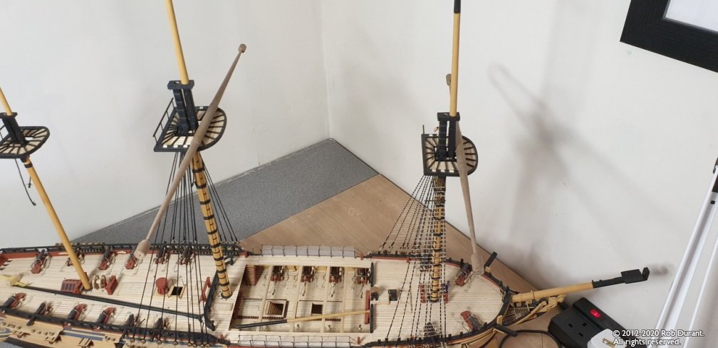
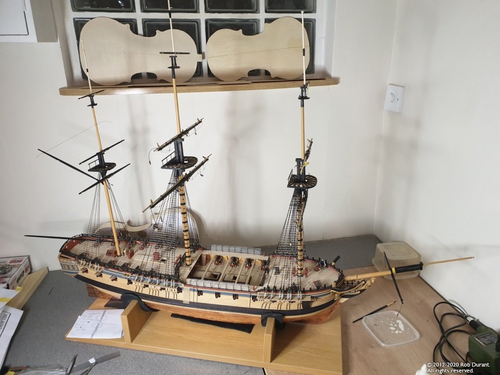
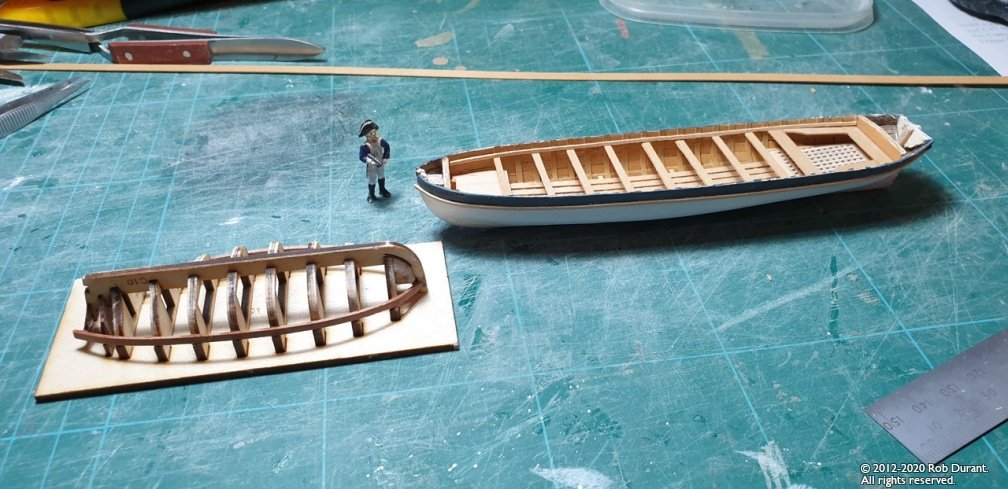
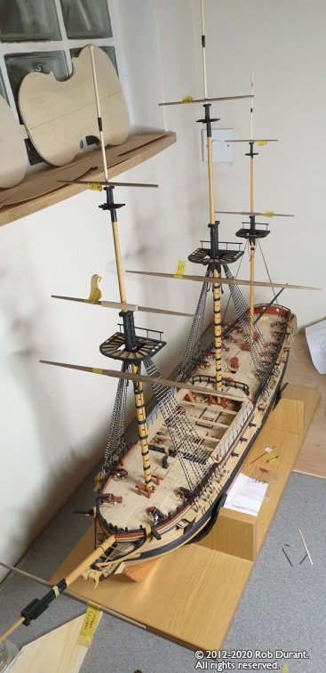
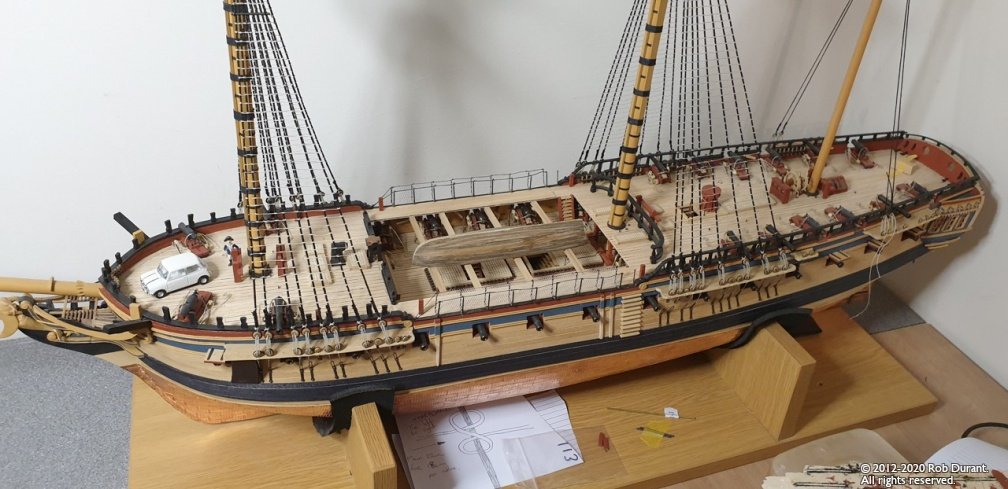
Okay - I had the opportunity to make some real progress yesterday, so by midnight the yards were turned, and I'm beginning to pin them into position. I really love this part as the ship really begins to take her final form... The yards are just pinned in place, so are removable. I'll try and put as much of the rigging on before I fix them finally in place. I'm toying with the idea of putting on royals as well - they turn up in the AOTS book, and I have the longer topgallant masts up, so I might just take the plunge. Could be fun! I've also been messing about with the boats. I had another crack at the pinnace that comes in the kit. It's by no means finished, but it's on the way. The following picture shows the pinnace with a just started vanguard kit of the 18ft cutter beside it. As a bit of fun, I bought a 1:64 model of a mini cooper (the Italian job model) and put it on the foredeck as a comparison... Not quite historical, but it gives you some idea of just how big these ships were. Happy building! Rob
-
Aah - now I looked more closely for them I found them right where you left them on the website. I'll revise my post above to note this. It's testament to your superb (and logical) design and laser-cutting that the construction was evident enough without the instructions, but yes, the instructions describe precisely the process I stumbled upon. I shall know to check the image icons more carefully next time Perhaps a specific link labelled instructions which opened that image would be helpful on the page? I'm so pleased with how the binnacle looks on the quarterdeck, and I notice you now provide the chimney as well - I would certainly have included that in the order, had it been an option then. As it was, I was simply challenged to think for myself, and that's no bad thing once in a while. Thanks Chris. Rob
-
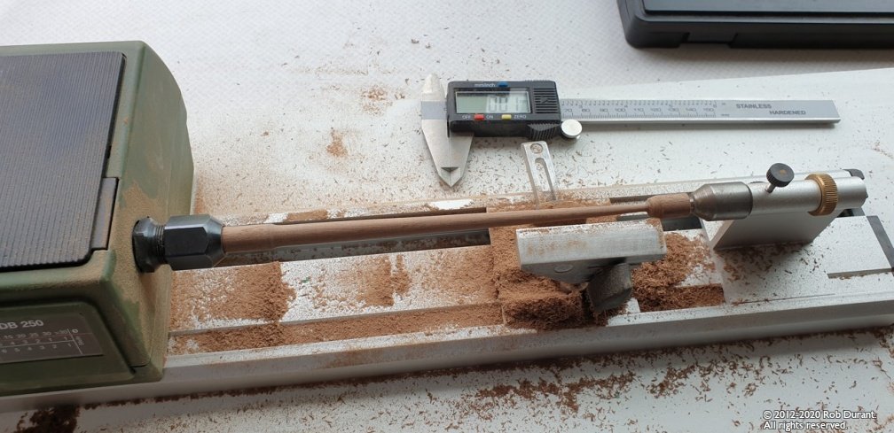
Not much to show, but I am still here. Thanks to everyone for the likes. As always, an encouragement - especially when tying knots one after the other. Mainmast ratlines are complete. I plan to get some more yards done on the lathe now as a break from tying clove hitches! Happy building Rob
-
It's definitely a stage worth taking your time over. It will save a whole heap of woe later if you get a smooth run for the planks to the bow.
-
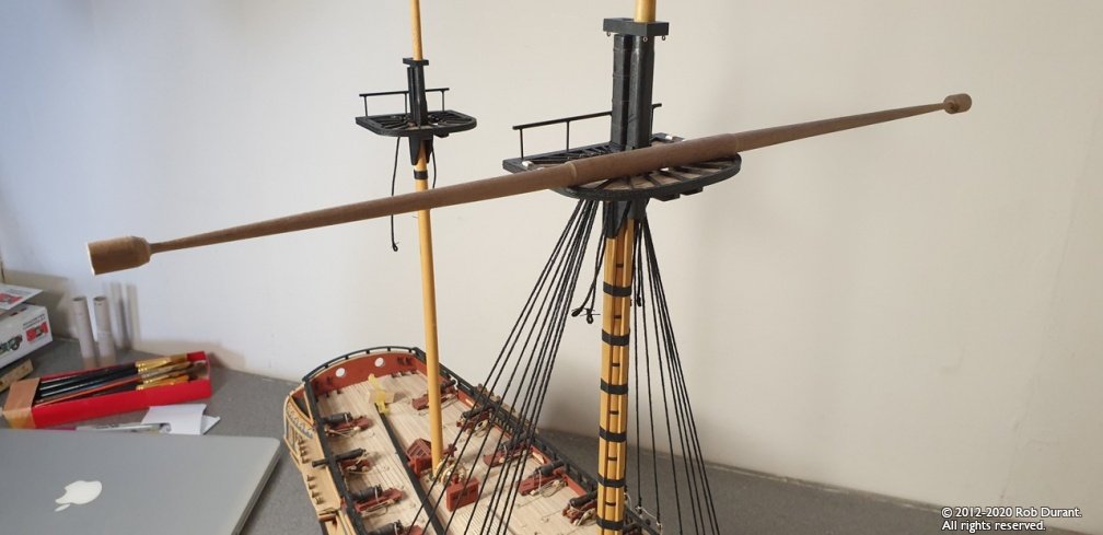
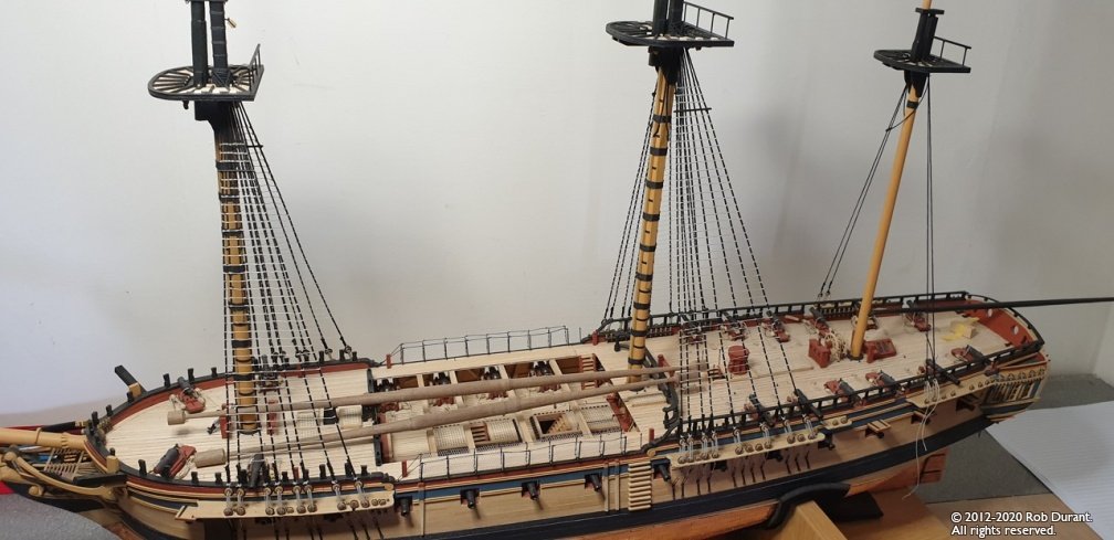
Well, the ratline tying continue apace, Foremast ratlines done, and the shrouds in place on the mainmast ready to rattle down... Nothing very exciting in terms of pictures... But I also had a nice parcel from Cornwall Model Boats containing the dowels I needed to get the yards done. So... Main yard and Fore main yard are begun. Here's my progress so far after an enjoyable hour with the lathe (just sat on top of the tops to get an idea of what they might look like). It's broken up the ratlines nicely Ready for the main mast now.