


robdurant
-
Posts
804 -
Joined
-
Last visited
Content Type
Profiles
Forums
Gallery
Events
Posts posted by robdurant
-
-
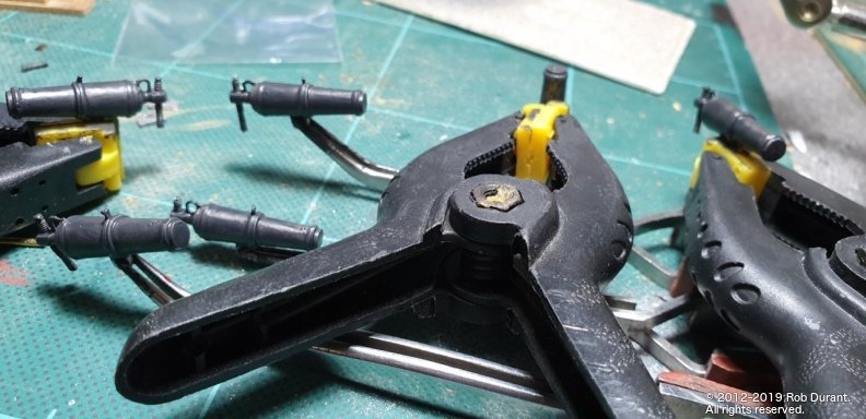
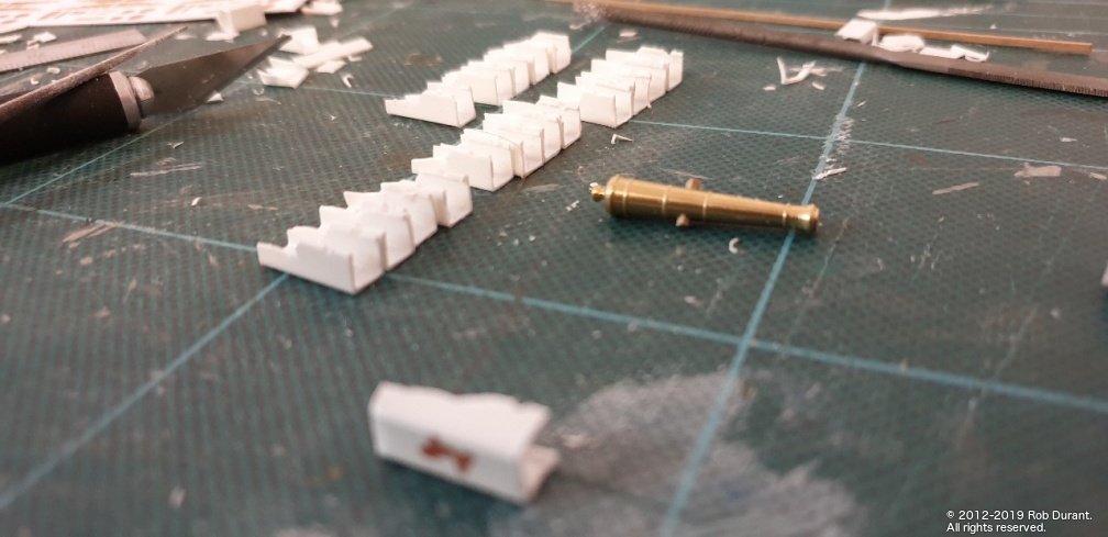
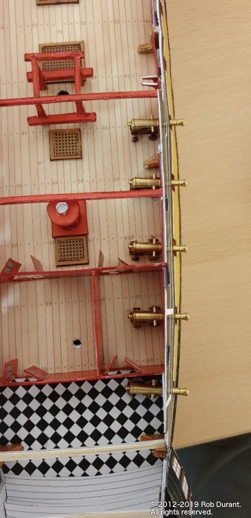
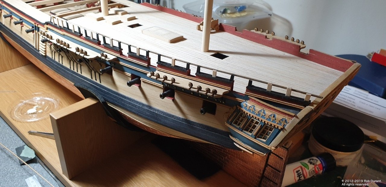
Time for a little update. The bulwarks are done, and I've been working on the quarterdeck armament... namely 12lb cannon (actually 9lb on the ship, but the carriages fit nicely) and 32lb carronades... The cannon are from Syren Model Ship Co. - these kits are fabulous, and I don't really do them justice! Step one for me is to build a framework around which to build the carriage. This helps me get them all square and neat.
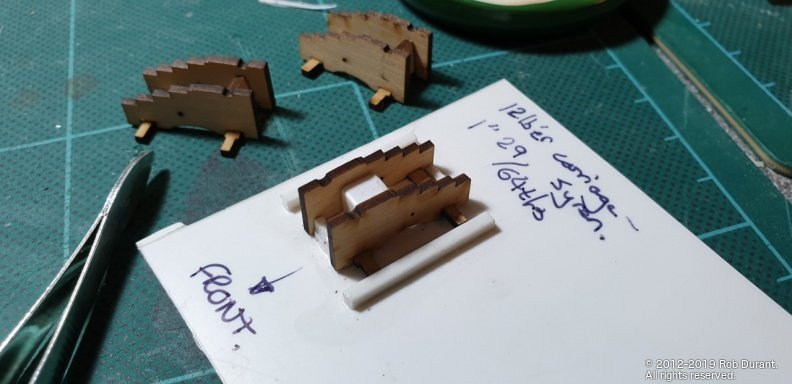
The following is a size comparison between the 12 and 18lb carriages... I hadn't appreciated what a difference it actually was.
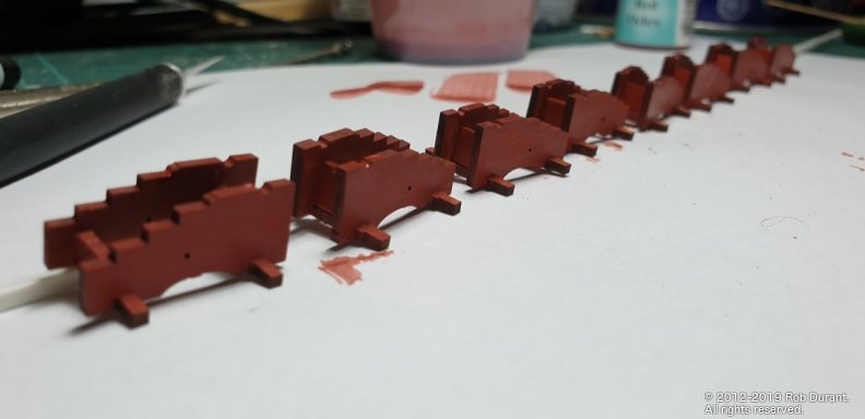
The wheels were sanded by attaching them to a rod and spinning them in sandpaper.
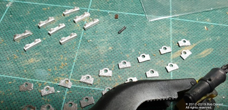
Next up were the carronades, which are Caldercrafts from the kit. I was expecting to be disappointed with the castings, but they were pretty good, actually. Some playing around was required after cleaning up the castings to try and make the Britannia metal castings match the cannon barrels which were blackened, and I'm still not quite there, but getting closer I think.
All the fittings were reasonably clean castings with minimal cleaning up necessary.
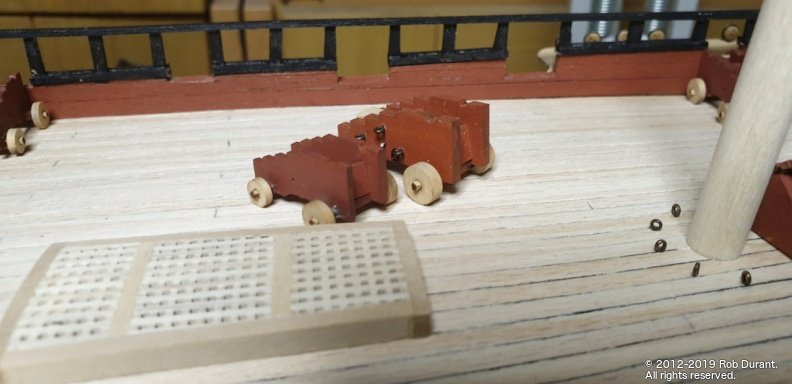
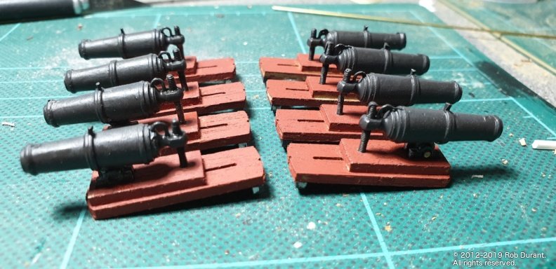
Production line in full swing... And all this is just for the quarterdeck!
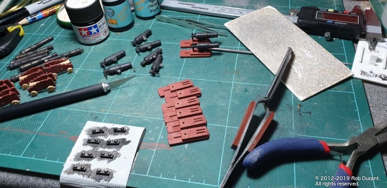
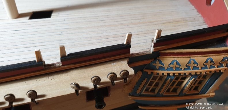
Since this photo was taken I've also drilled out the holes for the eyelets, and added the brackets at the front.
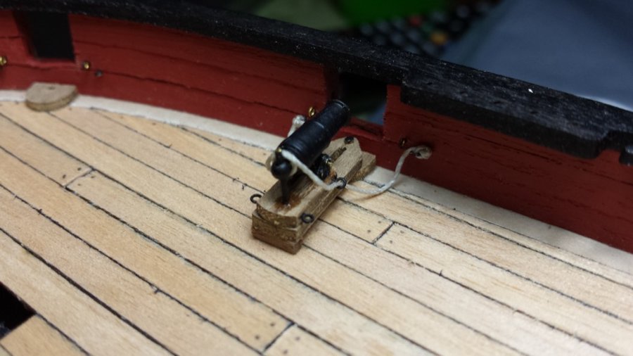
As other Diana builders have noted, the instructions suggest these ought to be mounted onto the sill of the gunport - however this practice was pretty much over by the time Diana was built, and instead the carronade was resting on a pad of wood on the deck beneath the port.
This arrangement can be seen on Victory's carronades, as per the picture below, taken by Julian Fong: (https://www.flickr.com/photos/levork/2302412091)
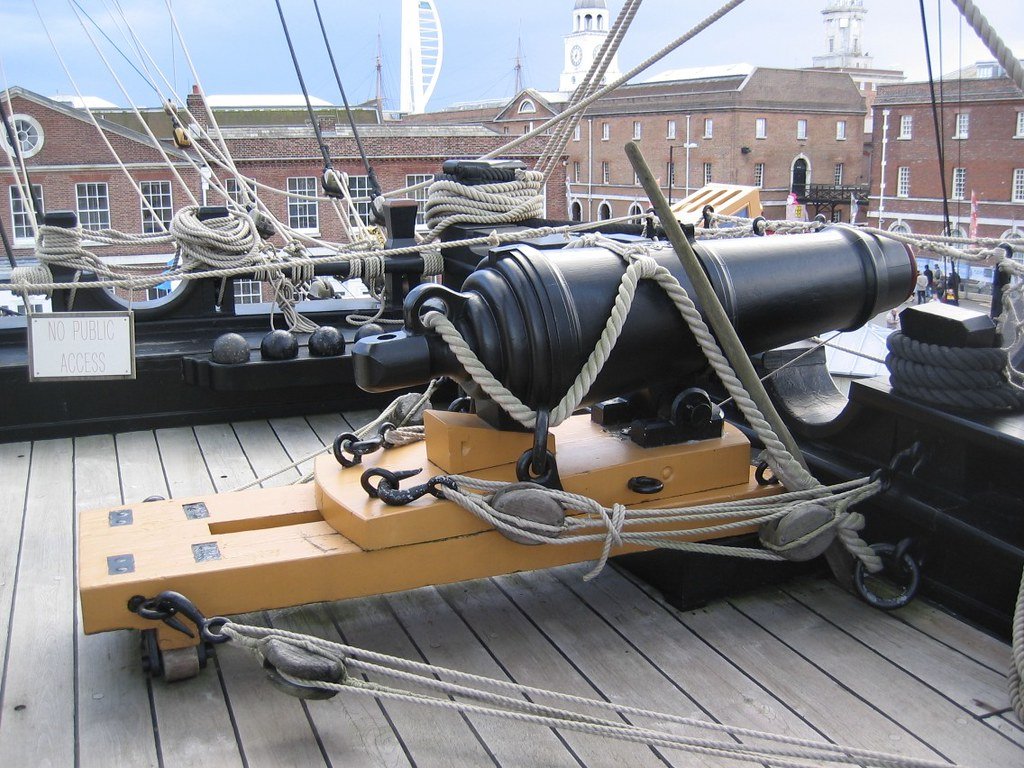
And even more clearly here: https://ageofsail.wordpress.com/2009/02/21/introducing-the-carronade/ , where the carronade has been swung up against the Bulwark, revealing the pad on which it sits.
- JpR62, Beef Wellington, egkb and 5 others
-
 8
8
-
I'd be surprised if it were to far out given that you have the lower deck in place... if you have a metre ruler and a set square you could check the keel for straightness and the frames that they're at 90 degrees to the keel, and then go along and mark the lines across the deck from each of the notches to the centre of the deck (at 90degrees to the centreline where you've made your cut) and see if they match up (that is to say it may be the deck that is mis-shaped) ... only a pencil, ruler, set square will give you the definitive answer. Once you know you can work out a plan of action.
Definitely.worth working it out before.you go too much further though.
Hope it proves to be a simple fix
")
Rob
-
Well, another trip to Germany gave me some more time to work on Mercury.
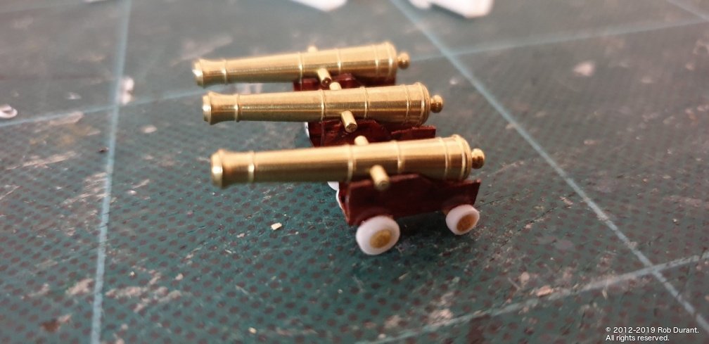
I'd been scratching my head about how to do the gun carriages. I ordered brass cannon, and when I tried to make the card carriages, they were both fiddly and not strong enough to hold the brass. It needed sorting, because at some point the fore and quarter decks need fixing down, and they'll make access to those gun positions impossible. I settled on using 5mm square plastic section. By taking one side off (the top) and shaping the sides, I was able to get an approximation of a gun carriage. It's by no means perfect, but this model is an experiment, and my first attempt, so I'm more interested in working my way through it than getting everything absolutely perfect.
Anyway... coupled with cocktail stick axles and plastic tube cut down for the wheels, it looks something like a cannon with carriage. (The wheels are waiting to be coloured). I've left the cannon brass intentionally to see whether I like it. The answer is, I wouldn't do it again on another model, but it does add a bit of bling! I may yet remove them and paint them. They're a bit gaudy for my liking and don't seem to sit well with the rest of the model.
I completed the "second planking", and added the quarter galleries and stern gallery.
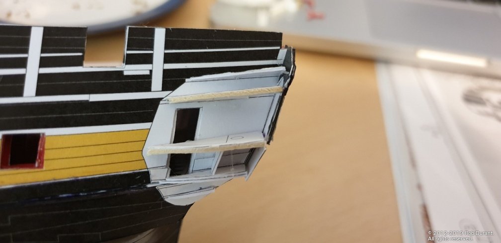
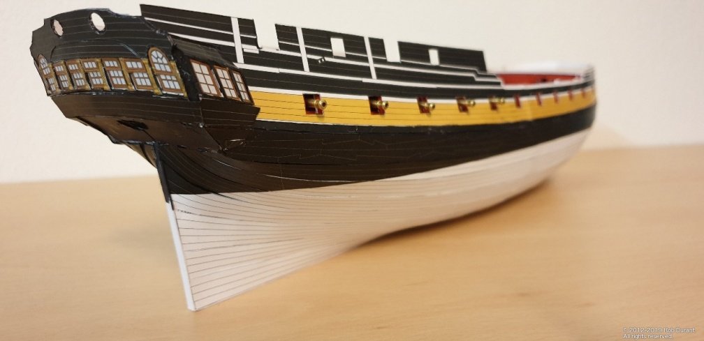
Where possible, I've tried to pre-colour the edges, but you can see where I haven't quite got the fit right, and the white has shown through. Something to bear in mind for anyone attempting a paper model that has large areas of black on it. I also neglected to build up the stern - I got over-excited and just stuck it all together, and then it was too late! Another lesson in measuring twice, cutting once! I think the depth of the stern would have looked much better, but there we go. That's how it is now... Something more like this, perhaps...
The final task was bringing Mercury home from Germany... I carried it carefully padded with tissues in a box... and it survived (only two cannon broke free, and it's all so small they did no damage at all.) I wanted to get it home before I started adding too many external details to the hull, so perhaps there will be more regular updated from now on. We'll see!
We're getting towards the fine detail part of the build now, so I'll need a new blade in the craft knife.
As a footnote, I answered my own question from above by re-reading the instructions from the model.. the thicknesses specified are of the card to which the paper part should be stuck. Thus where it says 0.5mm, the final thickness will be 0.5mm + the thickness of the original part. Perhaps that will help someone out down the road.
Happy building
Rob
-
Thanks Jason
Yes it's another challenge along the way. I've been able to place plank nippers in between the sideways planks to gently curve the whole lengthwise... seemed to work okay although the experiment did mean that it's now proving harder to complete the piece as it isn't flat. Something makes me think I should have seen that coming! 😂 🙄
-
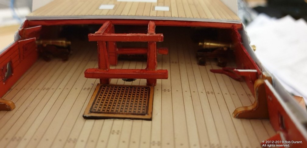
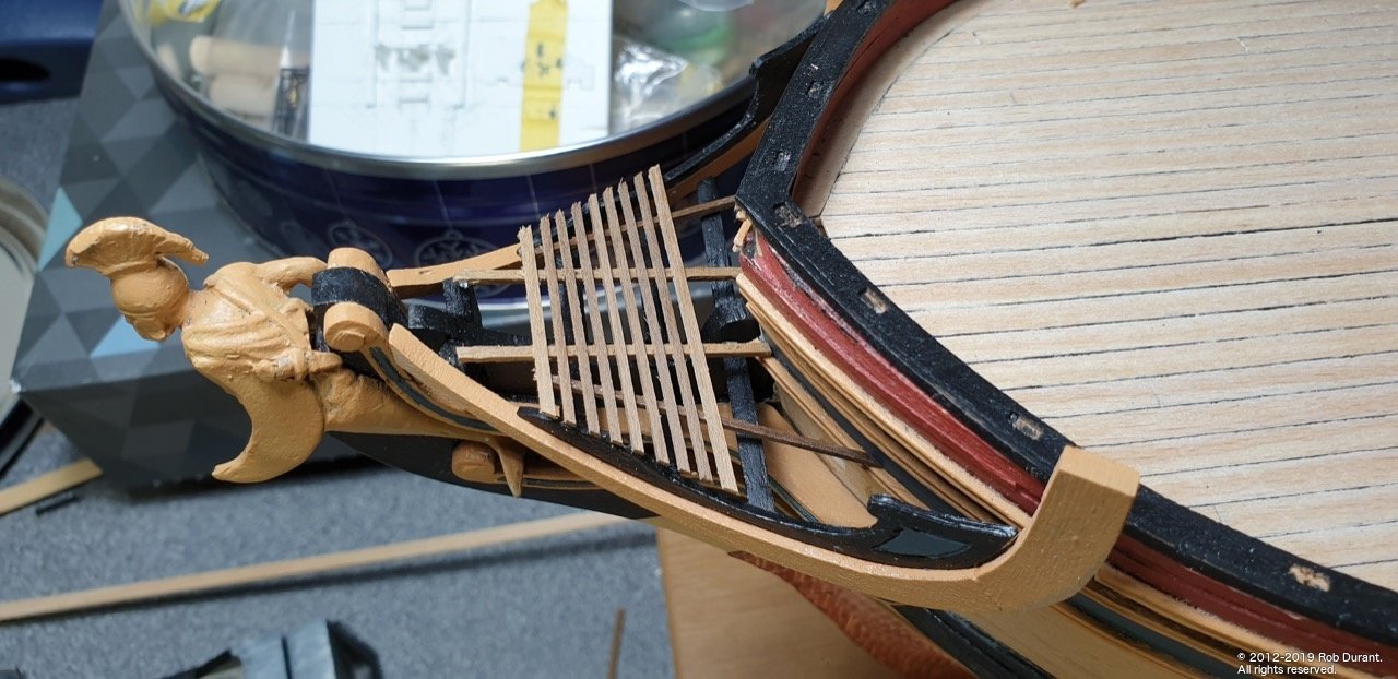
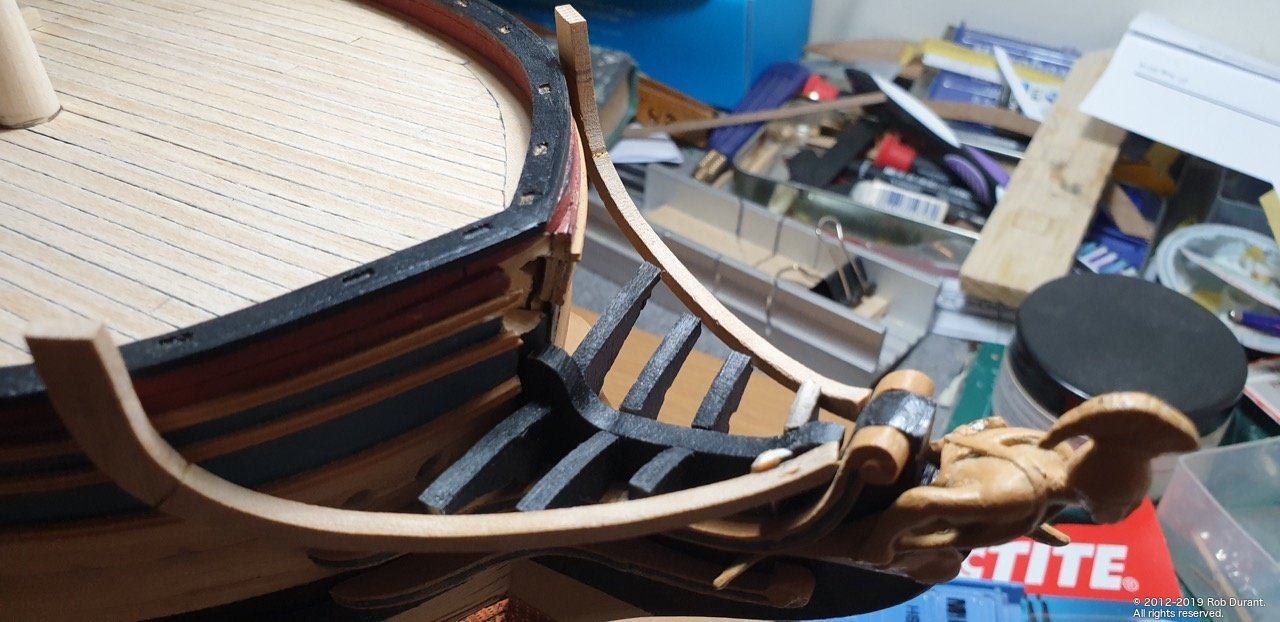
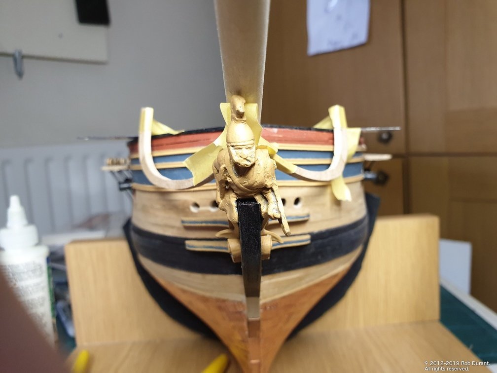
Another little update. More work on the beakhead railings... I've used plasticard, which I later engraved using a proxxon engraving bit to add the inset. This can be seen in the last photo of this post, with the first coat of paint on it. Hopefully this will provide a little dignity / privacy for those using the rear-most seats of ease!

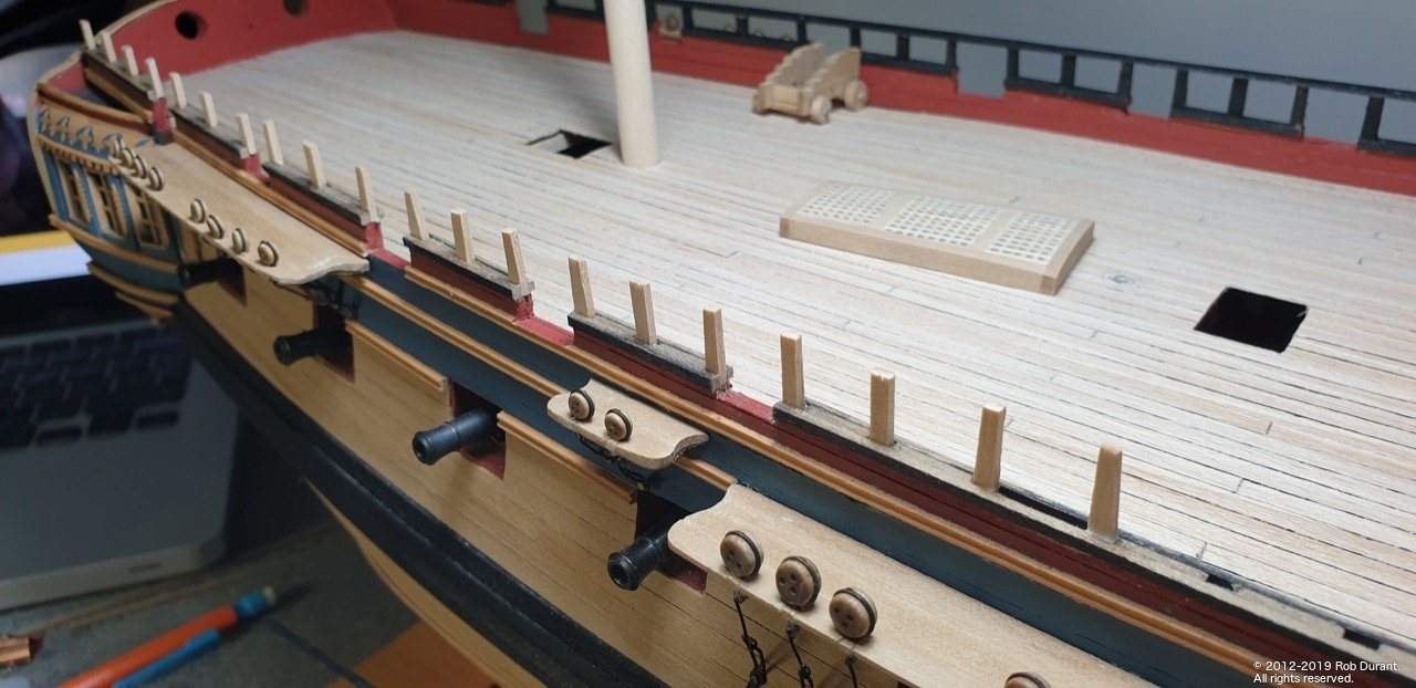
Some deck furniture... (the hatch was made form scratch, as the kit one ended up too wide, and looked a little clunky to my eyes. I haven't decided whether I like this open or not - the captain may prefer if it's shut so he can't be overheard discussing his orders by the whole ship's company, but if I leave it open I'll add a couple of rods to represent supports. I don't need to decide now anyway. In the bottom I put a square of card, which provides a little depth, but means I don't have to make the deck opening any bigger (somewhat tricky at this stage!).
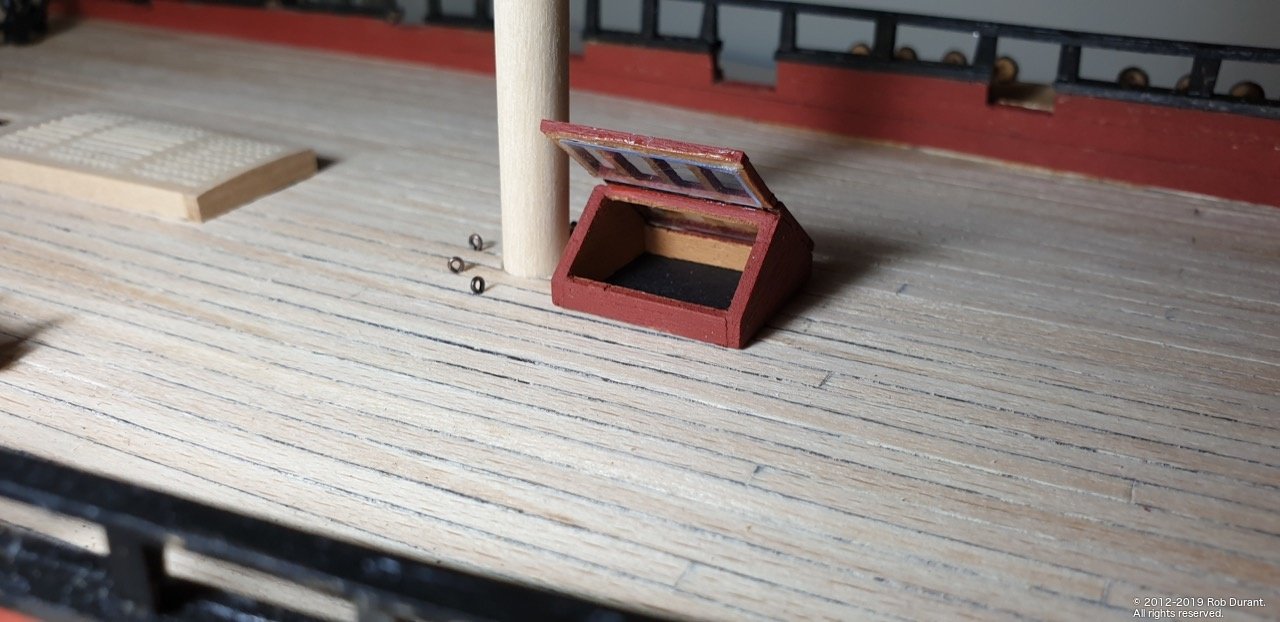
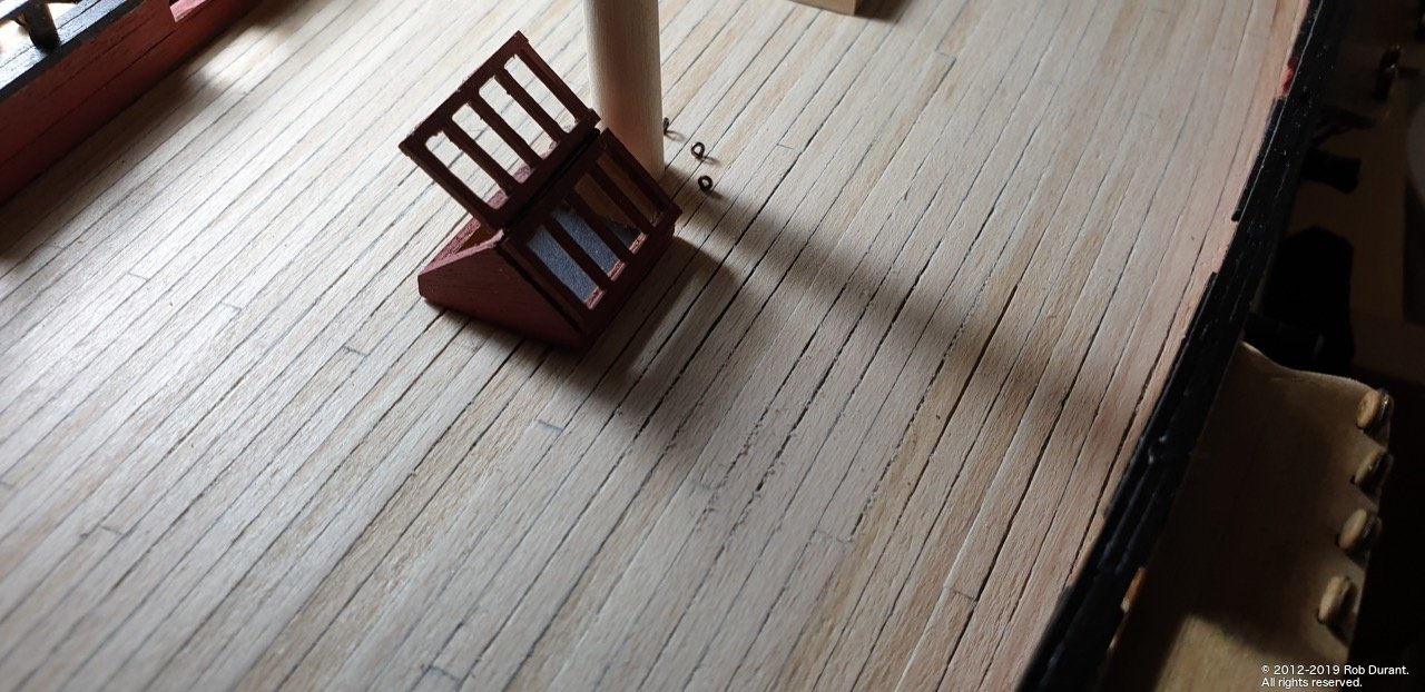
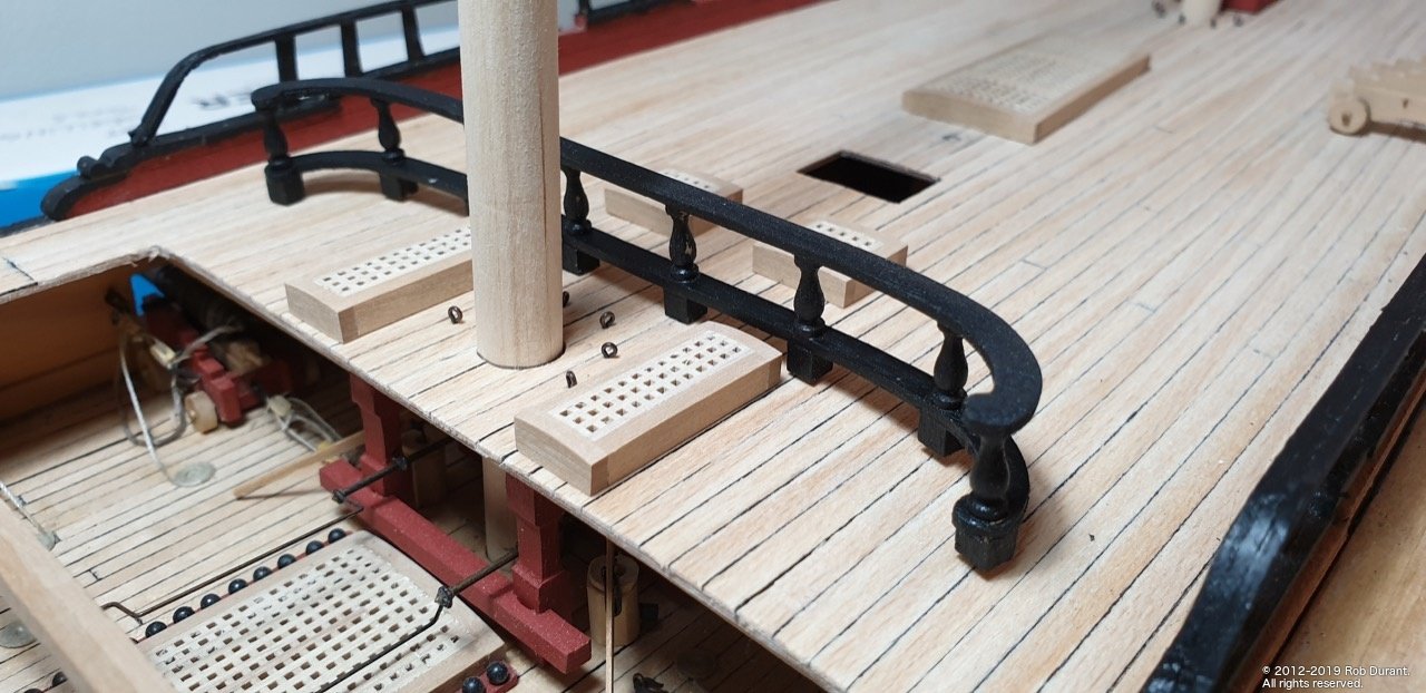
The balustrades aren't glued on at the moment, as I'm sure there will be all sorts of things that will be easier to do without them in place... the positioning holes are drilled, however.
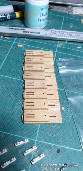
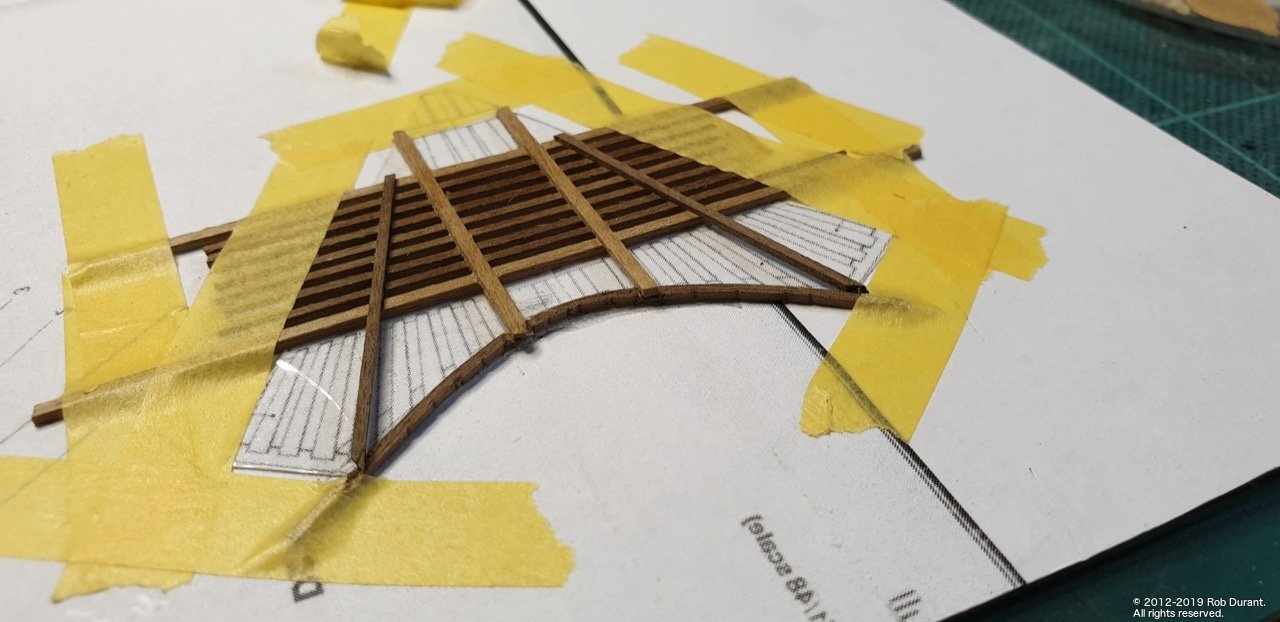
And the beginnings of the gratings that the seats of ease sit on. The shape is quite different from the kit shape, because of all the reworks I've done, so I've begun building this shape from scratch using the AOTS diagram as a template. I'm building them upside down. I've started cutting it down, but left it slightly oversize, so I can fit it closely once it's somewhat more complete. I also want to curve it as I go... Hmm... we'll see how that turns out! It's made out of 1x1mm and 1x2mm walnut strip, so I will need to paint it.
- J11, GrandpaPhil, chris watton and 5 others
-
8
-
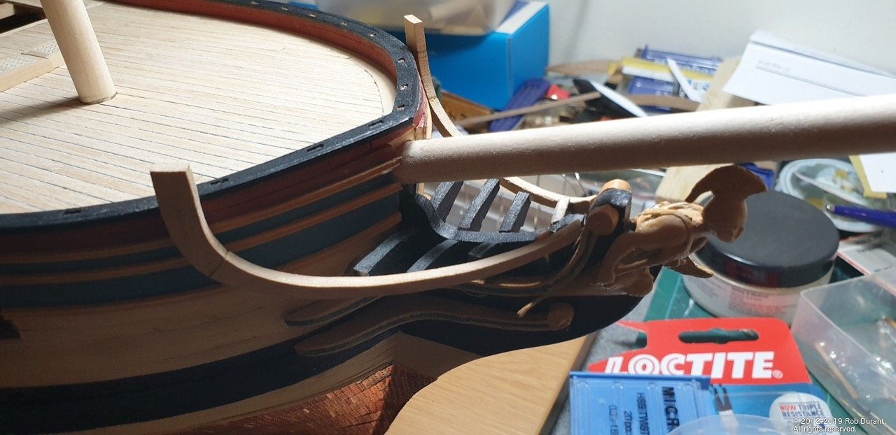
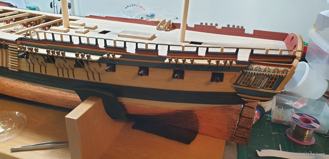
More progress on the railings and the bow over the past few days. A bit more work to do yet... but progress all-the-same. It is helpful working on one end of the boat while glue sets at the other! I need to weigh Ethalion at some point to find out just how heavy it's got.
-
Thanks for all the likes, kind comments, and encouragement.
A mini-update to end the day... The railings have had their first coat of paint... This angle seems to show every slight imperfection, but they look much better in real life
-
-
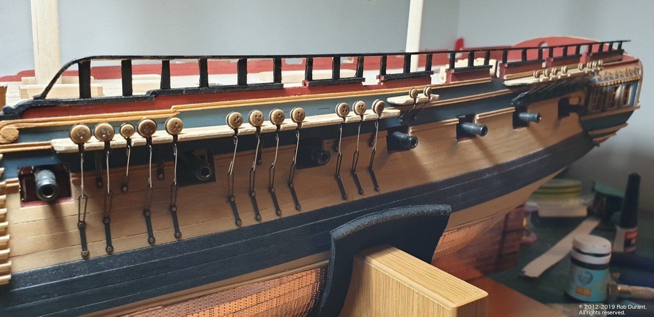
A small update... the port channels all have their deadeyes and chainplates attached. I need to fill the gaps in the channels and smooth them back, but it's nice to have this done.
I've also been working a little more on the open rails on the quarterdeck. I've started filling in the central row of the top railing with 1x1mm walnut, and then I'll put the rail on the outside edge to complete. A 1mm brass wire was added at the bow end to straighten up the rail. It should be virtually invisible once complete, but should add strength too, for when (not if) I knock it!
Happy building
Rob
-
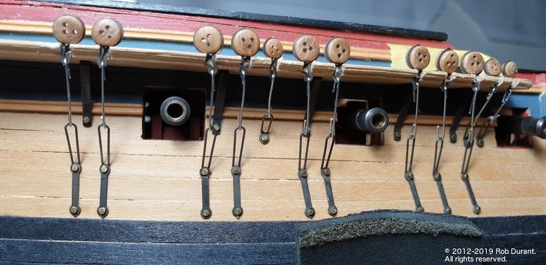
Because of the tiny size of these carronades you may decide to simplify... normally you have two things going on...
1. A thicker rope that goes round the back of the gun and fixss to either side of the gunport. This is to contain the recoil.
2. thinner rope used to haul it out ready to fire.
3. Also on the pic in the last post you can see another set used to point the carronade. (Training tackle)
On my model I decided just to put the breech rope...
But this is where each of our models ends up unique... regardless of what you choose I'd recommend making up a template for where the holes will go on the hull and drilling them out using that so they all end up uniform. It maybe worth trying one off the model in a card mockup to see if your plan will work.
Finally as you drill the holes watch out they don't pop out on the other side
Rob
-
11 hours ago, Peterhudson said:
Question: when, and with what, did you varnish the boxwood? I don't want to damage it when I start to fiddle with fixtures and fittings so am minded to do it after the copper is complete.
Hi Peter,
I haven't put any finish on the parts that will remain unpainted, as I didn't want to find I'd put a finish on and then couldn't attach other parts (steps etc..) to the outer hull, but at various stages as I've worked, I've used paper and masking tape to protect it as I work on other parts - especially when I've been painting things. I'm still in two minds about how to finish it. In the past, I just haven't used anything, but I think I'd like to do something this time. The wipe-on poly that seems to be so popular in the states seems harder to get hold of over here in the UK, and I'm wary of using oil in case the surface ends up sticky and attracting everything in sight... some testing will be required, I think.
Great start on the copper plating
It goes pretty quickly once you get in the groove...
Rob
-
-
17 minutes ago, mugje said:
find it a bit weird that Caldercraft didn't use solid pieces of walnut,
Hi mugje,
I expect solid walnut at that sort of size would have been too fragile as it would split along the grain... plywood walnut is a better material for the task, but it does bring with it the challenge of tidying it.up to look neat. The alternative would be a harder finer grained wood such as european boxwood, but it's very expensive compared to walnut.
Well done with those carronades! They look fantastic... much neater than my effort... Pickle was my first wooden model too. Keep up the great work.
Rob
-
20 minutes ago, Beef Wellington said:
Great progress Rob, must be a great feeling to have reached this point.
Thanks Jason.
Yes it does feel like a milestone... not too far until the hull is done and then onto the masting and rigging!
-
Just found this log. great to see you making a start Vane. looks like you have a few projects on the go there. They're going to make a great shipyard when done.
Rob
-
Thanks Vane. I think you overestimate my skills
After a fairly long break over the summer, with Prince of Wales finished, it's time to un-stall this project and get it moving again.
Things that need doing:
- Finish the channels on the port side (dead-eyes, strops, chain plates, etc.. ) (Starboard is complete)
- Work out how to create the open rail on the quarterdeck.
- Move on with the beakhead rails.
These have all proved to be head-scratchers for me, hence the tentative progress. But I think yesterday I made real progress.
Rails:
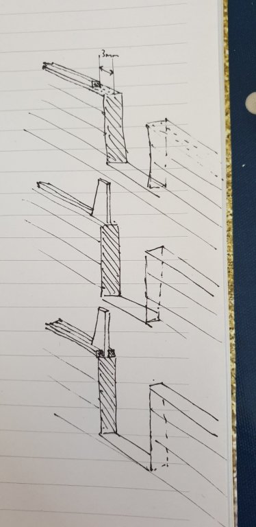
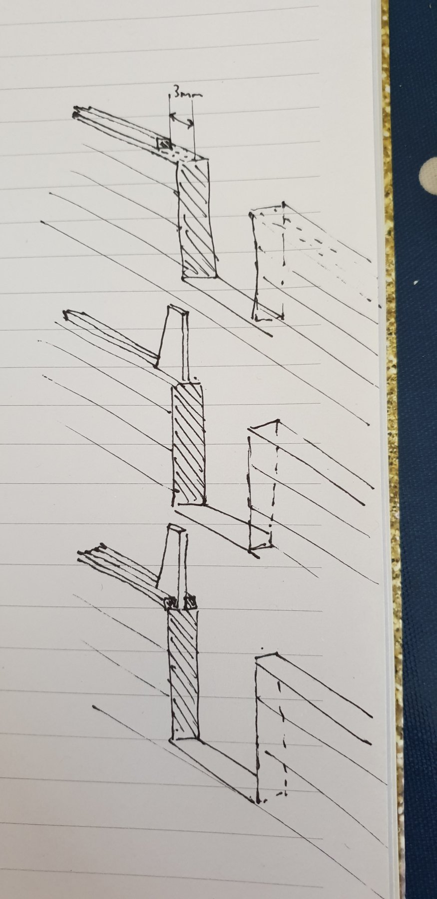
Before I went away I glued a 1.5mm square strip of walnut down the centre of the top of the quarterdeck rail. I cut sections out of this for the gunports and to 3mm of each side. The uprights will sit here. Now, I glued a 1.5mm square strip of walnut down the outside (pre-painted to avoid a nightmare cutting in later). 4mm maple was used for the uprights, which was cut to size using the attached diagram.
Openrails.pdf (an A3 diagram)
Progress so far is encouraging.
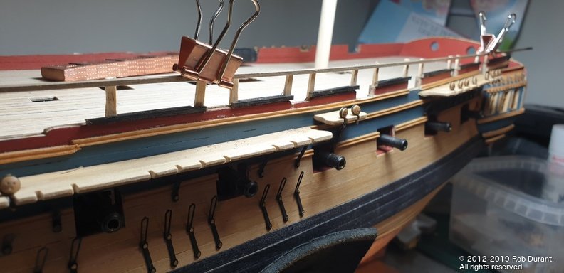
The top rail is only dry-fitted to get an idea of the height and how I might add this part. (probably a variation of how I did it at the bottom).
The channels are also coming on. Not much to show here as the process is exactly the same as for the starboard side.
- chris watton, KARAVOKIRIS, Barbossa and 5 others
-
8
-
That looks like a good fix you've done there. Great progress! It's going to look even better once the walnut's covered up.
Are you planning.to copper it? I may have mentioned before but I would highly recommend the vapour mask (not the same as a dust mask) I pointed to on my log if you're using superglue.... it takes a lot of the stuff over an extended time and it saved it messing with my lungs.
I've just got back to Ethalion after a big break over the summer so it's encouraging to me to see your Diana coming along so well.
Rob
-
Hi Jason
No need to apologise. Glad of your excellent input.
Rob
-
Hi Vane,
Thanks for your encouragement
The Anatomy of the Ship on HMS Diana note nine ships as you mentioned. Of these the seventh and eigth (Clyde and Tamar) were built out of fir rather than oak (the latter being in short supply by that point in the Revolutionary Wars. The final, Ethalion, was built out of oak again.
You can look up the plans for each of the ships on the Maritime museum's website, and that's where I began my search when I was thinking about building Ethalion instead of Diana. As it turns out, the differences between the sister ships are somewhat lesser than the differences between the kit and the actual frigates. These differences include the width of the stern, and so the layout of the gallery and stern lights, etc..., the layout of the gun ports, and the layout of the channels to name but a few. The more you look, the more you'll see subtle differences.
The following is a side-by-side comparison of Ethalion, Artois, and Jason (from the RMG plans) compared to the Anatomy of the Ship plans for Diana to give you an idea of some of the subtle differences. If you look at the mizzen channels for Jason and Artois you'll notice they're split, whereas Ethalion (and Diana from AOTS) are the same. That has a bearing on where the chainplates land around the gunports towards the stern, but the hull shape remains unchanged.
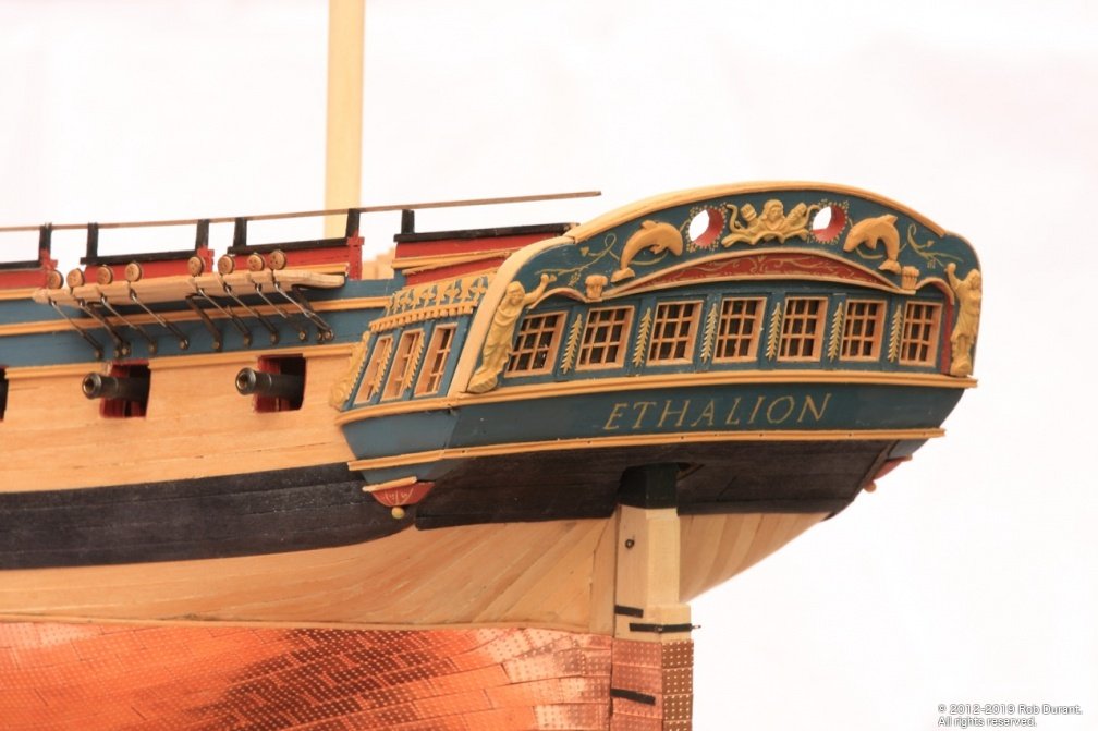
One of the more noticable differences as well is the bulkheads on the quarter deck... on Ethalion here. they're open - vertical pillars with a rail on top. On Jason and Diana below, they're enclosed (as the kit Diana depicts)... I've chosen to build them open - a decision I may regret when I get there! but I believe Ethalion's rails were enclosed in a refit. Also Ethalion's rails terminate at the fore end in a vertical... the others are more ornamental.
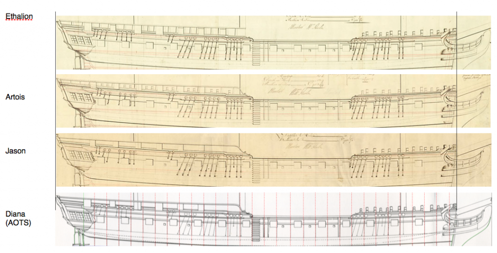
The diagram above is comprised of pictures from the following links from the Royal Museums Greenwich website:
http://collections.rmg.co.uk/collections/objects/82225.html (Ethalion)
http://collections.rmg.co.uk/collections/objects/82174.html (Artois)
http://collections.rmg.co.uk/collections/objects/82195.html (Jason)Also, the profile from diagram A1/1 by David White in Anatomy of The Ship - The Frigate Diana. For comparison purposes only.
I trust having cited these there will be no copyright issue, but please advise me if this is incorrect as I will happily remove the image.
Having said all this, my primary desire was to build a ship that hadn't been built before. One must be careful when doing this not to accidentally end up using plans of other ships that had the same name (i.e. Ethalion 1802). I found following the historical trail of the ship fascinating, and it really did feel like I was treading on scarce travelled paths in doing so. I was able to go into the National Archives and read the master's and captain's logs which was a true privilege.
The Diana kit is a great challenge, and a tremendous kit... it's not only big, but about as beautiful as shipbuilding got. I wish you every success should you follow me and others building these frigates. Do make a build log! It'll show me where I could have done better
-
Well, I couldn't resist
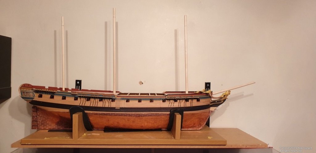
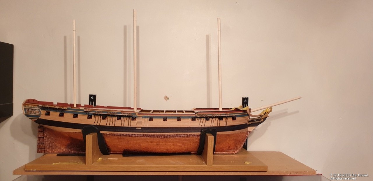
- The stump masts were looking a little.... stumpy?
So I sat down and worked out what lengths I thought the masts ought to be... AOTS has them as being significantly shorter than the Jotika plans - two to three centimetres.
This is what I came up with...
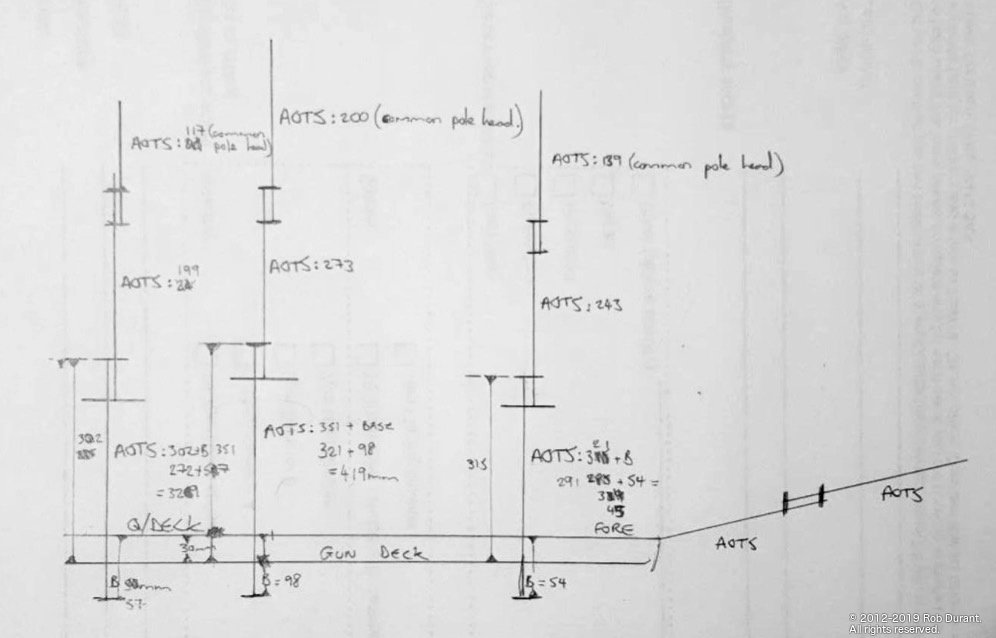
So the measurements are taken from the bottom of the mast to the upper deck (marked "B") - this was measured from the stump masts, I'd already made. Then the second measurement was taken from AOTS diagram F1/5, F1/6 and F2/1 from the upper deck braces to the top of the mast. By working out the distance between the upper (gun deck) and the fore / quarter deck above it (which turned out to be approx 3cm) I could then work out the entire length of the mast from mast step to top. As I said, this ended up 419mm for the main mast, 345 for the foremast, and 239 for the mizzen. Top and TGt masts were also calculated using the AOTS diagrams F1/3, F1/4, F1/5.
And here it is, with some scrap left at the top of each mast for when I put it into the lathe to turn it down...
In other news, I also attached the channels on the port side today, and drilled the holes for the chain plates to attach to the hull.
As always, thanks so much for the likes, and here's to happy building!
Rob
- BenD, Ekis, Beef Wellington and 2 others
-
5
-
She's looking great Peter
keep up the good work. I've been surprised how this step up in model complexity means I have to draw on my perseverance more. It's all worth it though.
-
On 6/21/2019 at 10:31 PM, Beef Wellington said:
How did you actually taper the planks to the right shape
Hi Jason, I worked out the dimensions at 5 cm intervals, and then planed, then sanded some 5mm square strip to those widths (they were only shaped on one side, so completely flat on the other. Those were used as the templates on either side of the strips, which were laid down edge down in between those strips. Once held tightly in place with masking tape, they were sanded down with a sanding strip. It took a while, but once done they were all done in one go. The hardest thing was handling all of the strips and getting them lined up and fixed down in the first place. It was an exercise in patience. I've tried to draw the process below...
I've also attached the plan I made of the deck based on measurements from my model... (I wouldn't recommend relying on these measurements for yours too much, as I know I could have done a better job with the fairing of some of the bulkheads, so I have a little bit of a bulge on my model, but it gives an idea.)
On 6/21/2019 at 10:31 PM, Beef Wellington said:Been a little absent, but very enjoyable to catch up on your wonderful progress Rob, must feel good to have the upper deck on and planked. How did you actually taper the planks to the right shape (sanding, cutting,...?) - you achieved a very nice curve.
Will certainly be picking your brains going forward. The headwork are honestly a head scratcher to me and I've been mulling that over for many months as I think many parts will need to be scratched to get a pleasing look. As you point out, the kit supplied parts are not the right shape, and the ply is just horrible quality (at least mine were). I'm trying to decide whether the grating s should be a series of flat sections, or one continuous curve as I've seen on some models, the latter obviously being rather more challenging.
Yes, this really is one of (if not the) most challenging bits of the model. I haven't worked it out yet either, but I'm relying on lots of card templates, eyeball 1.0, and plugging away bit by bit. I figured if I got the rails in place, I could start thinking about the gratings. Curved gratings? That does sound like a massive challenge. I think I may go for a number of flat sections... perhaps if the turns were gentle enough a curve could be sanded / scraped in (using a template with sandpaper over the top, or a curved scraped used across, rather than fore and aft) rather than building it curved? Just thinking out loud. I may use the kit supplied parts as a starting point and see what they look like.
I haven't made the vanity rail yet, so that's the next challenge. Also, I need to work out how to scrape a nice profile on the head rail as it changes width... and thin it down a bit.
Anyway - those are my thoughts so far
A few deadeyes to secure on the channels first. Starboard finished, but port still to go.
Happy building
Rob
- egkb, BenD, KARAVOKIRIS and 4 others
-
7
-
Time for another small update. Small because of late I've found myself sitting staring at the model when I get a little time to work on it, and not achieving much beyond that. Oh well, the ship's patient with me!
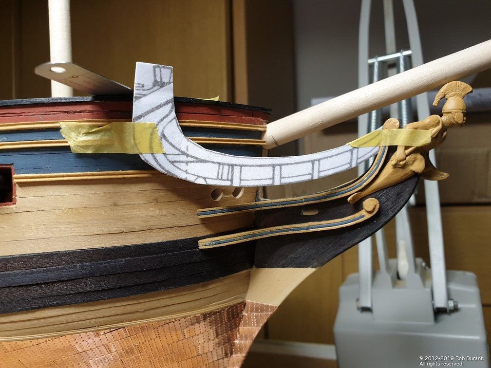
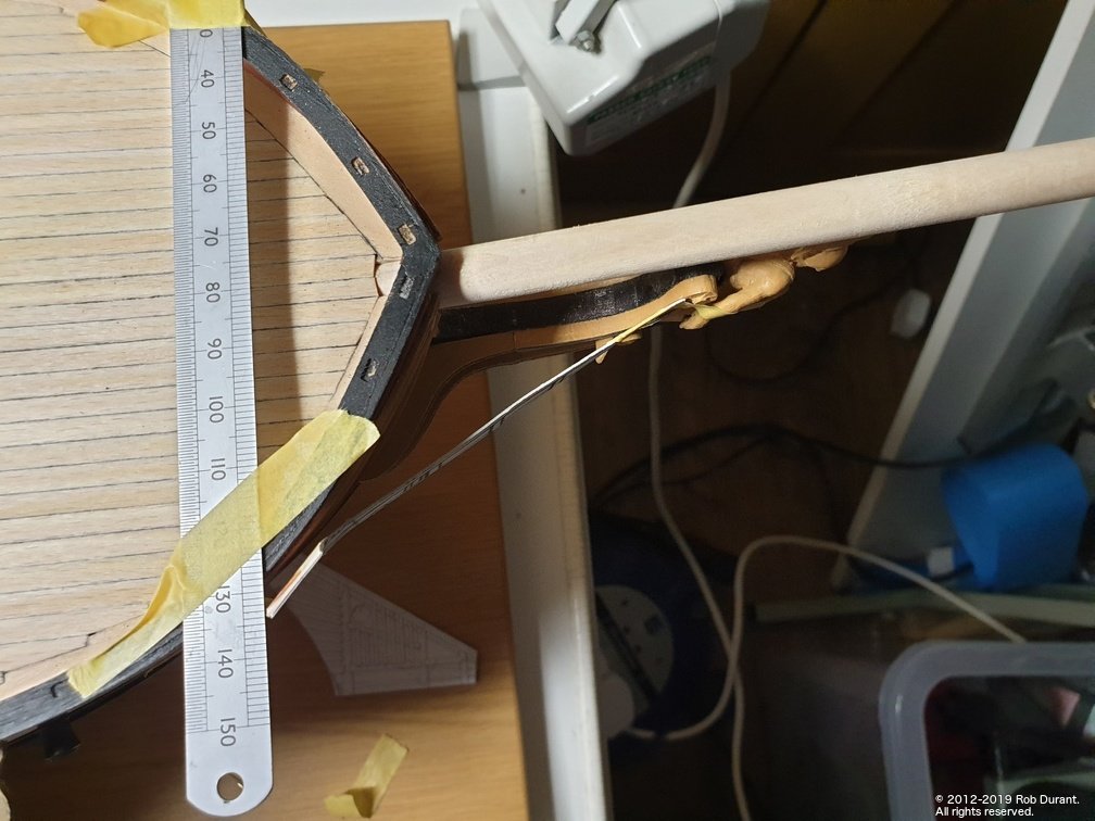
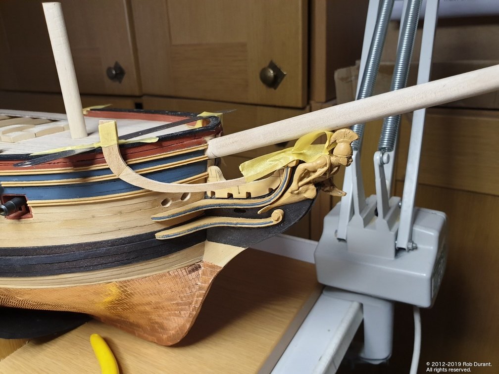
Anyway... For a break in the channels, I've been looking at the head rails. The top rail needs to be made up before you can see where the other rail, and all of the parts that sit on top of the beakhead go.
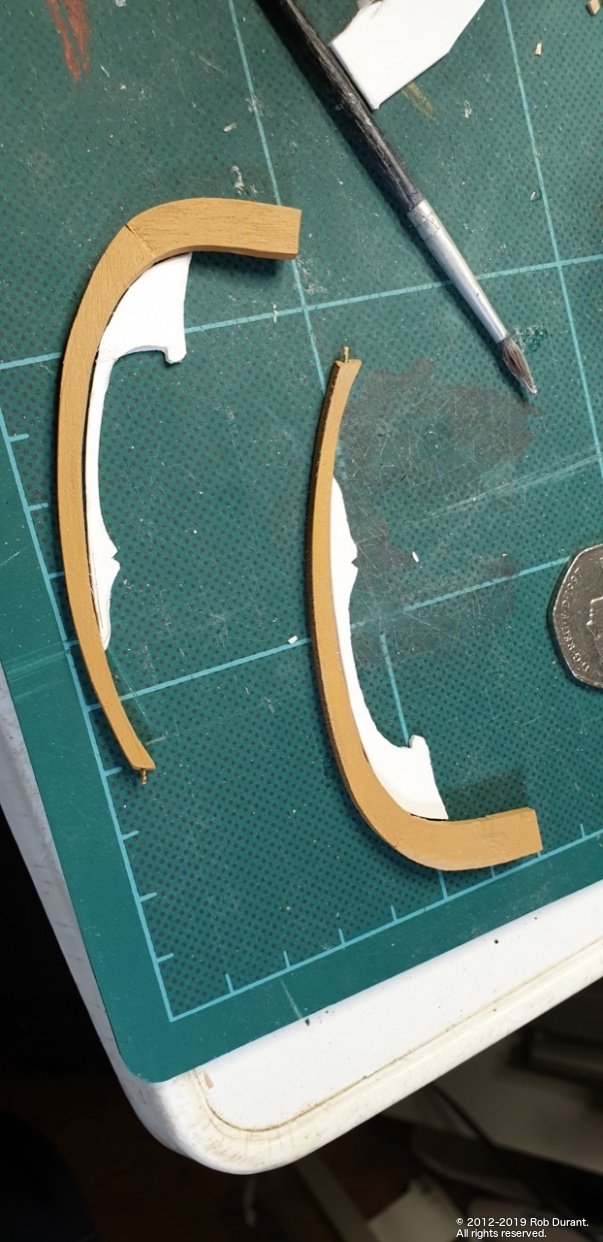
I wanted to make these parts up so they reflected the AOTS / NMM plans shapes more closely than the kits parts. To that end, I stretched the plans (which started at 1:64) around the bow by 114% on the x-axis, which by my calculations allows for the angle the rails are at on the plans. Then I printed them out, made a card mockup to trial it, and then pritt-sticked them onto some cherry (in two parts so that the grain was running along each part) and cut them out.
And here are the results... (roughly taped in position for a trial)
The redeeming feature of these headrails is that they're straight when you look at them from the top. It won't be so easy for the middle rail, which seems to bend in every direction possible. This will at least give a good reference point for starting out making that part!
- Beef Wellington, GrandpaPhil, MEDDO and 6 others
-
9
-
Hopefully the soaking will work. I've used the Amati plank nipper which seems to work quite well...
The third item down on this link - black plastic:
https://www.model-dockyard.com/acatalog/Manual_Plank_Benders.html
I know there are differing opinions on these, but I've found them really helpful
The other alternative (and perhaps the way that is less damaging to the wood) is heat... You could take a look at Chuck Passaro's planking videos (link below) as they describe this technique. Chuck's results speak for themselves!
I haven't tried this with walnut, so I don't know what your mileage might be. Hope that's helpful though.
Rob

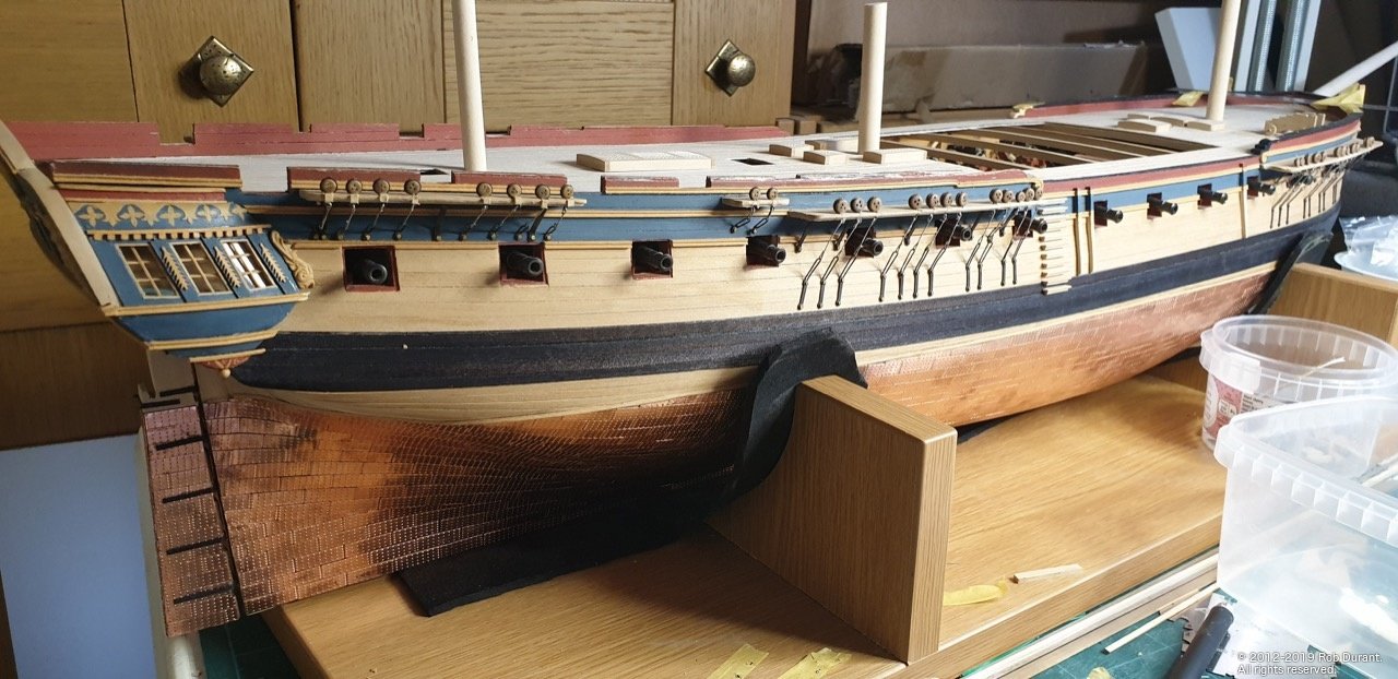
HMS Ethalion 1797 by robdurant - FINISHED - Caldercraft - 1:64 - Modified from HMS Diana 1794 kit
in - Kit build logs for subjects built from 1751 - 1800
Posted
Just a photo") - quarterdeck armament taking shape...
- quarterdeck armament taking shape...