


Paragraf
-
Posts
45 -
Joined
-
Last visited
Content Type
Profiles
Forums
Gallery
Events
Posts posted by Paragraf
-
-
-
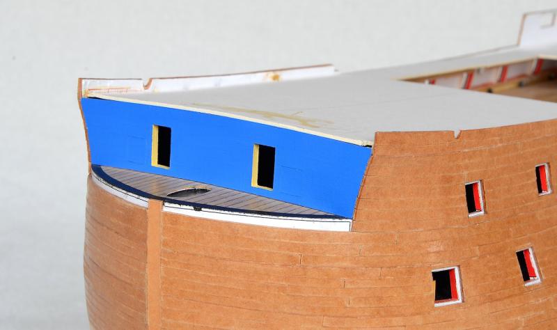
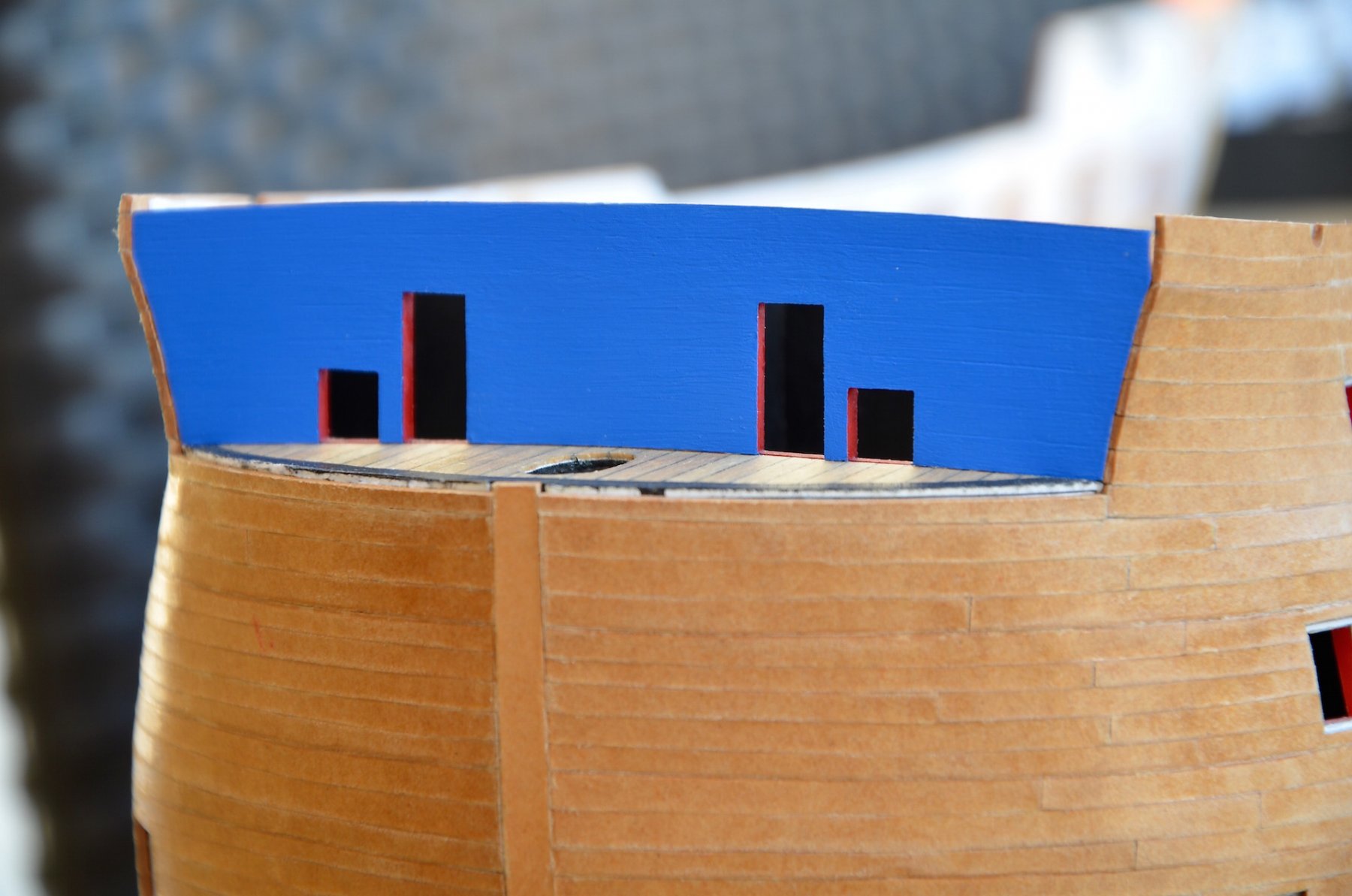
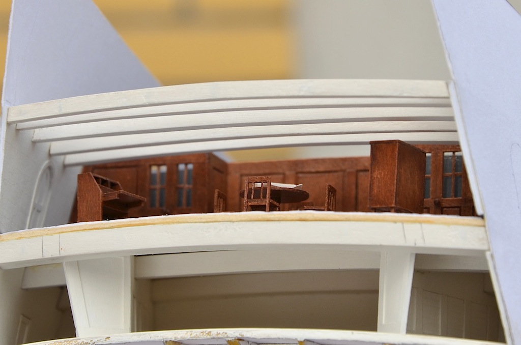
Hello.
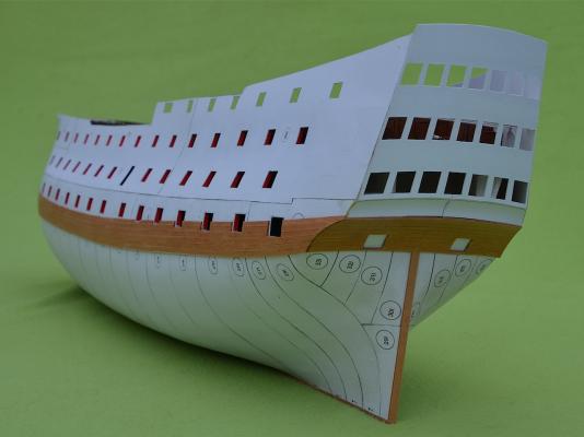
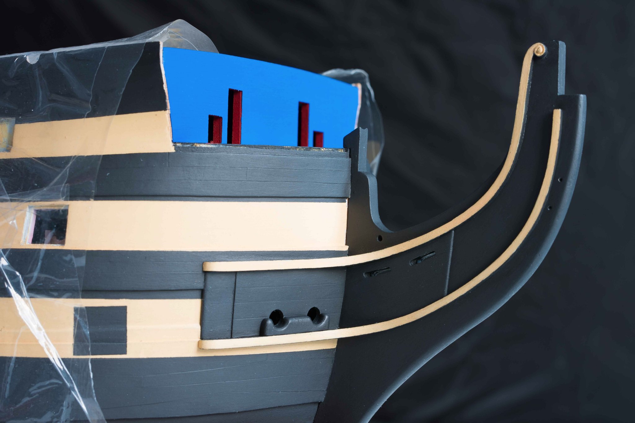
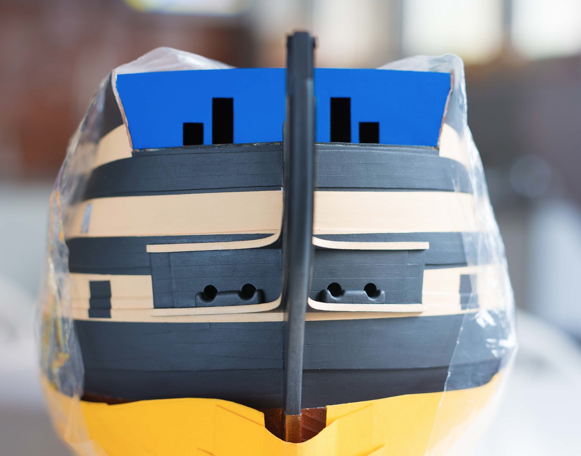
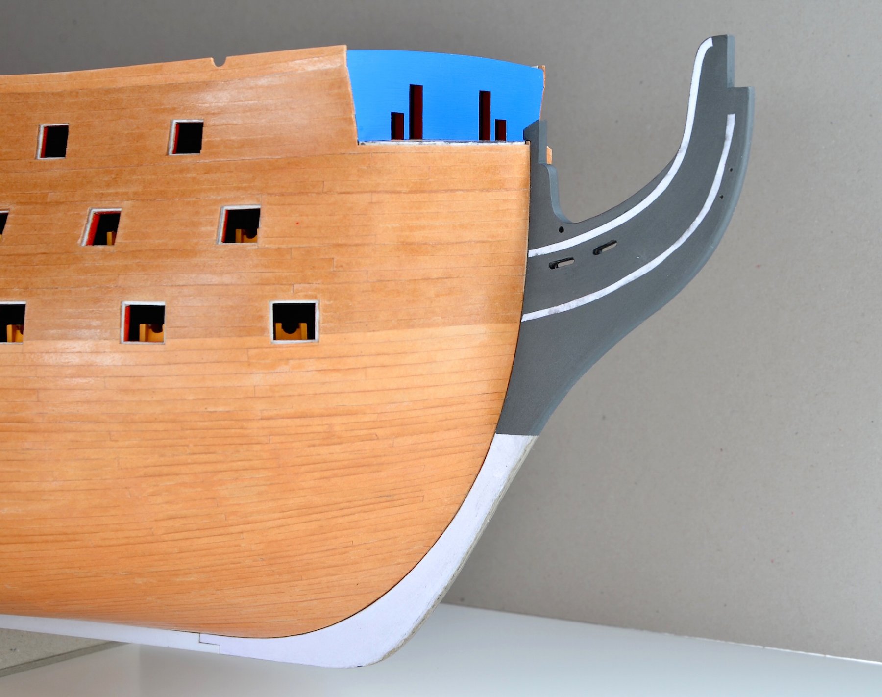
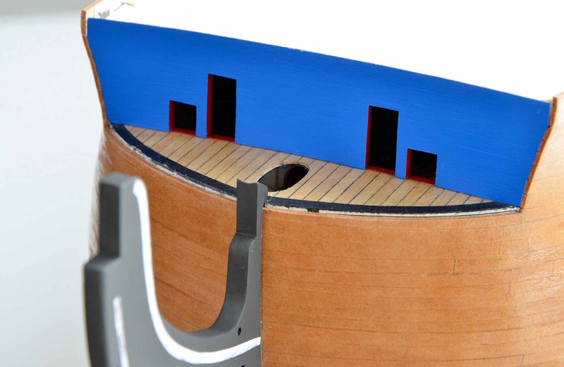
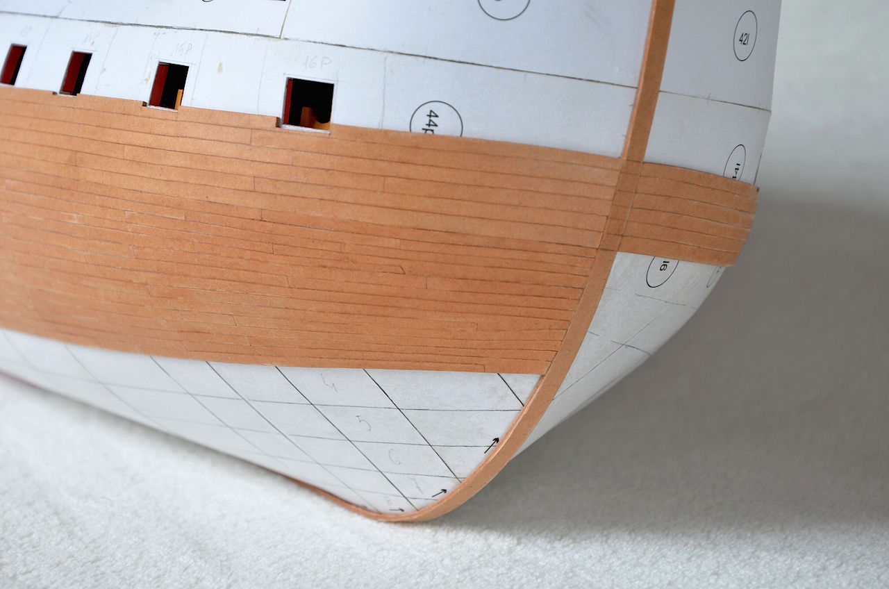
Small update of work in the bow section.
The timbering at bow is not glued yet, because I have to do both main rails first.


- VTHokiEE, clearway, GrandpaPhil and 5 others
-
 8
8
-
-
-
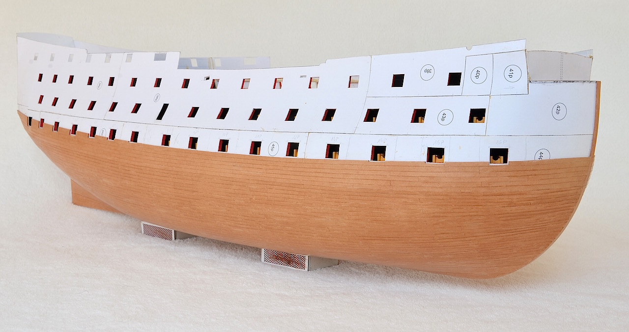
Hello.
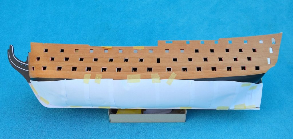
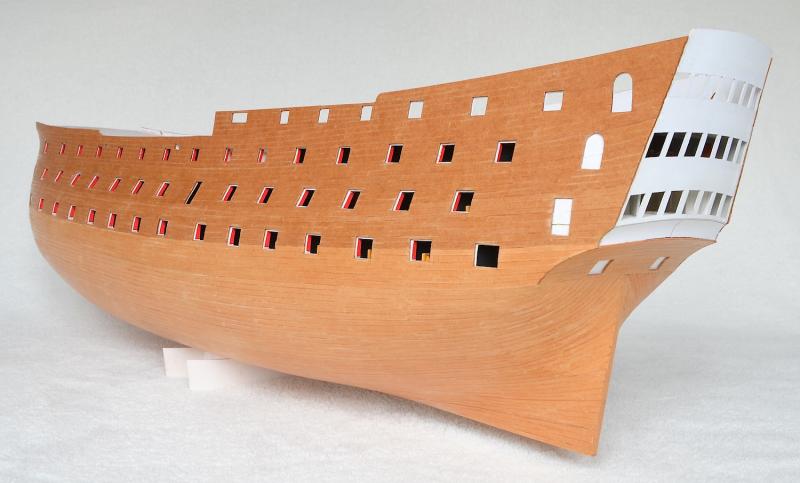
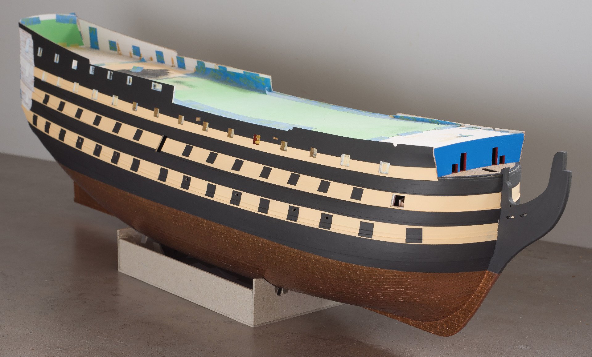
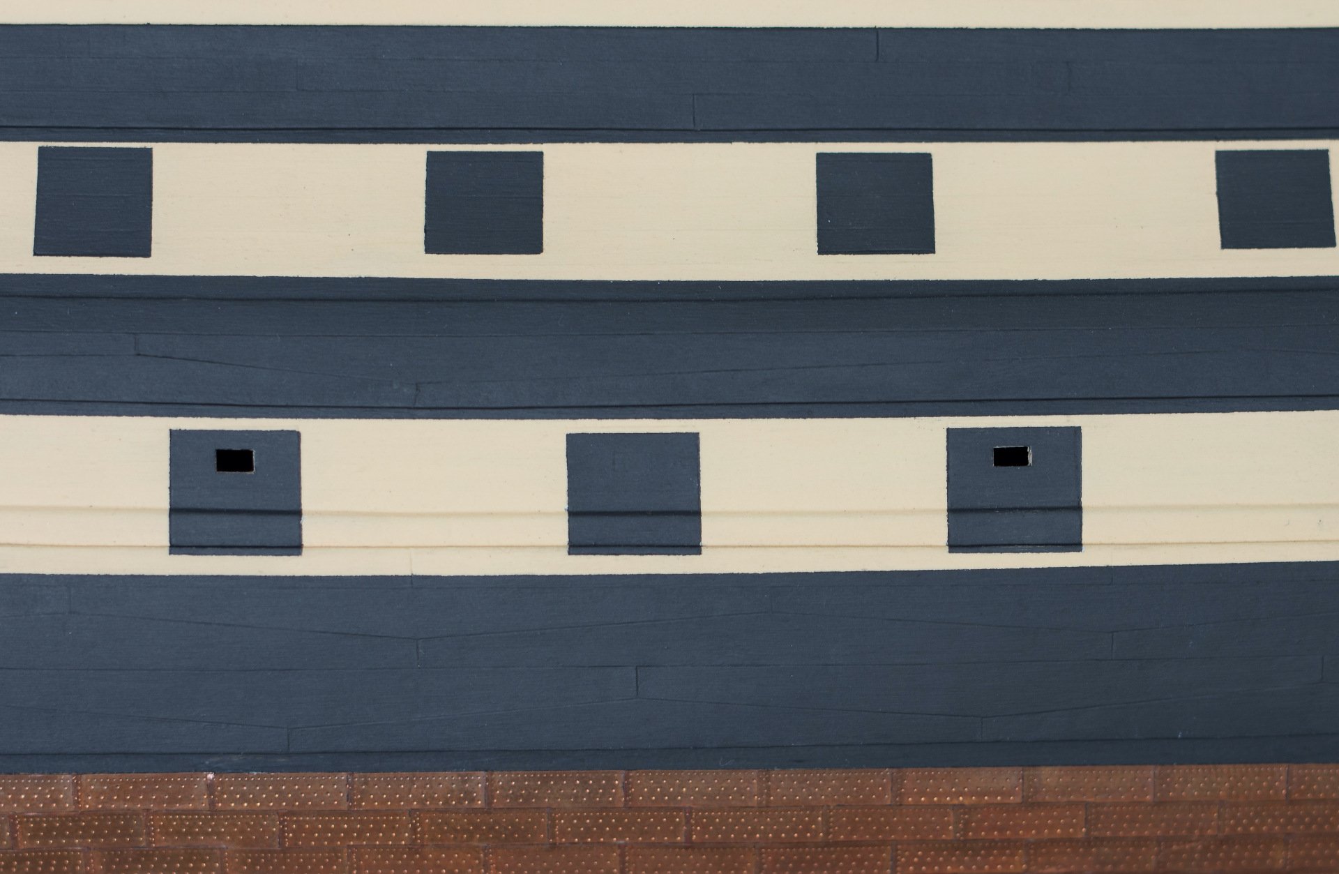
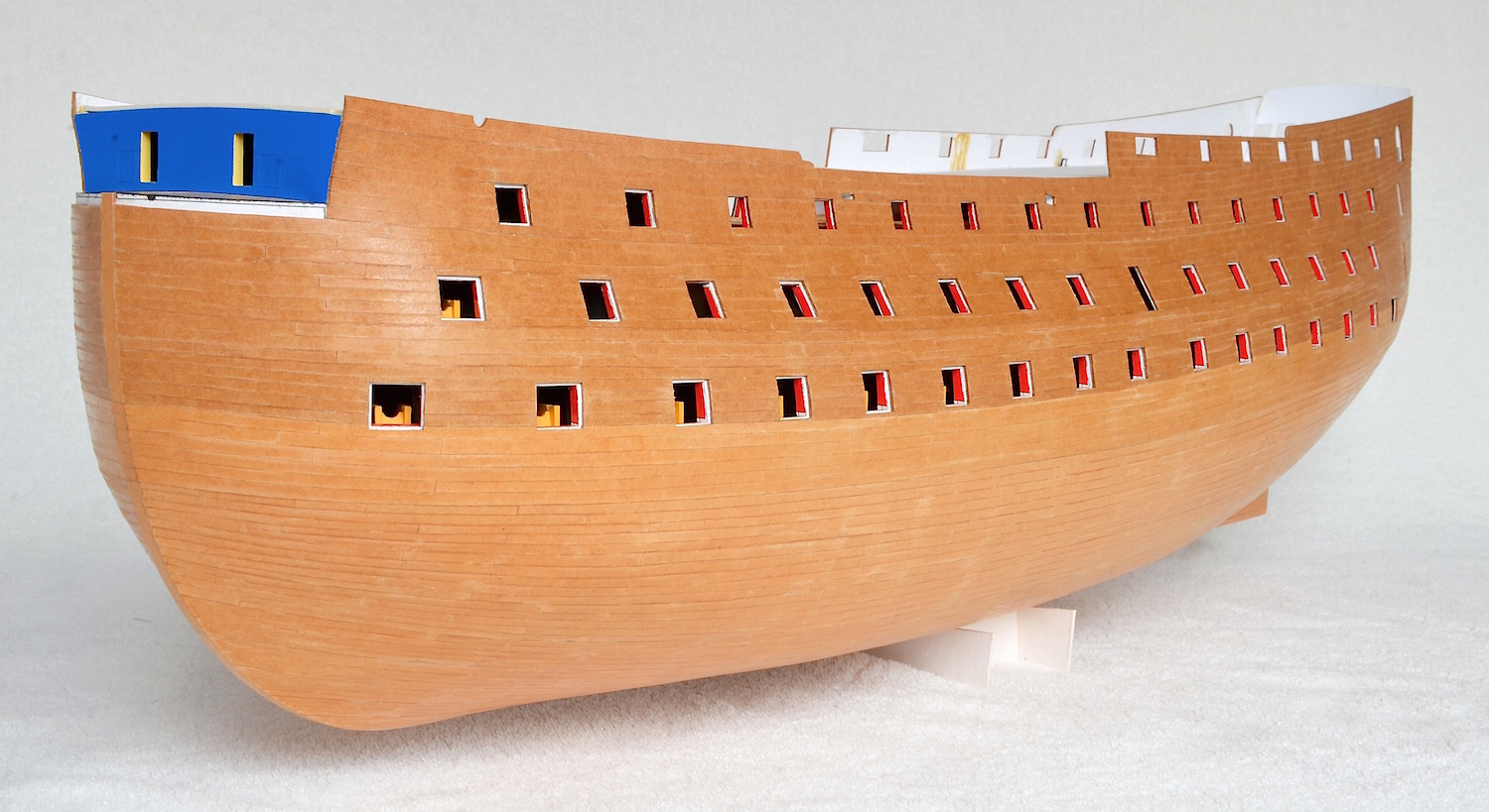
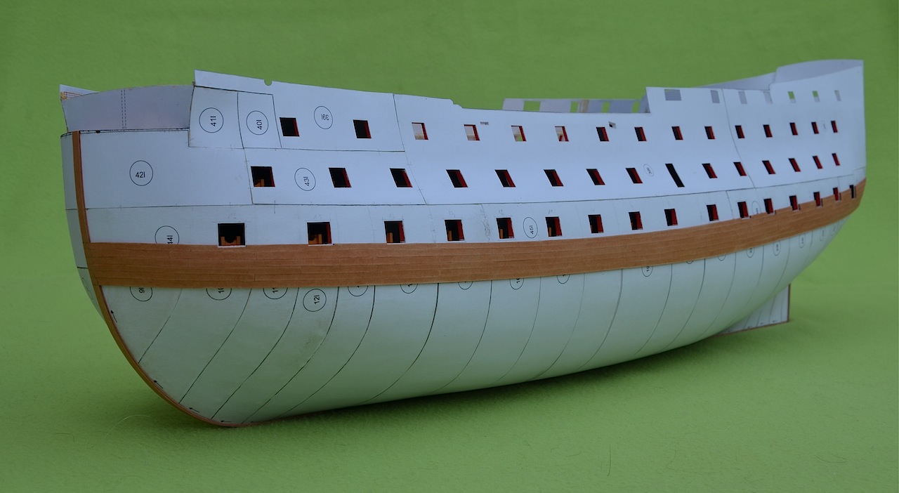
I haven't been here for almost two years, but I'm still alive and so is my Victory. As you can see in the photos, I decided to change the concept of the model and make it with the lids closed. I saw a model made in such a way and I liked this „checkerboard pattern” on the the sides so much, that I decided to do it also in my ship. So there will be no visible guns on the two lower decks.
Before painting the model I've made the main, middle and upper wales on the sides.
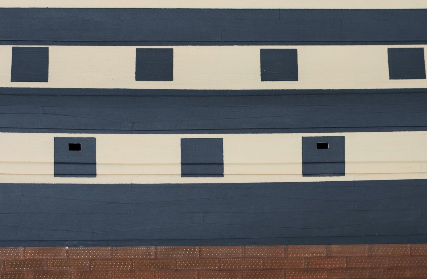
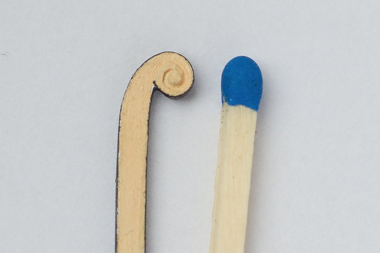
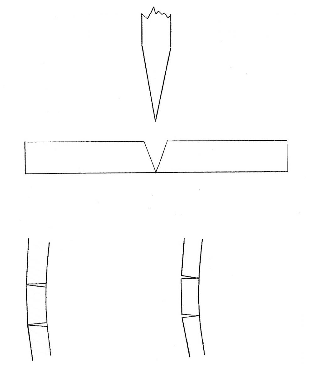
In Victory the main wale was put on in „anchor stock” planking. Each plank was fashioned with a double taper from the center of one edge, so that the planks laid side by side looked something like the stock of the anchor (see pict. below)
The middle wale was put on in similar, but not the same pattern. One edge of the plank was tapered, but insted of the tapers being equal in length one was quite twice length of the other (see pict. below)
Some people may notice, that the shape of the planks I've made on the main wale is slightly different than on the other models. In many models, the main and the middle wale are arranged in the same way, as in the second picture. Various sources give different information about the arrangement of these planks. I made them according to the description given in Longridge's book. Interestingly, on the current ship you will not notice the wales arranged in the so-called anchor stock.To be continued...
- Pitr Obrębski, GrandpaPhil, Rudolf and 4 others
-
6
-
 1
1
-
-
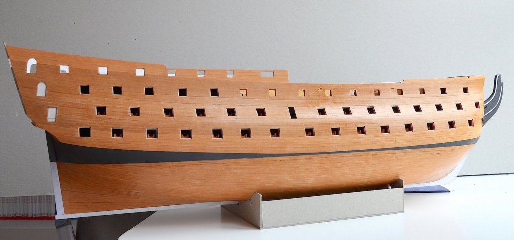
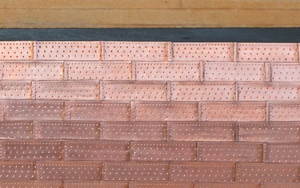
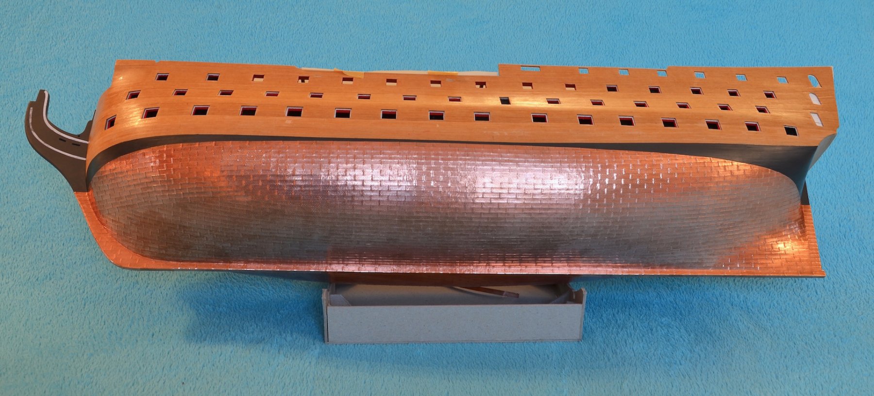
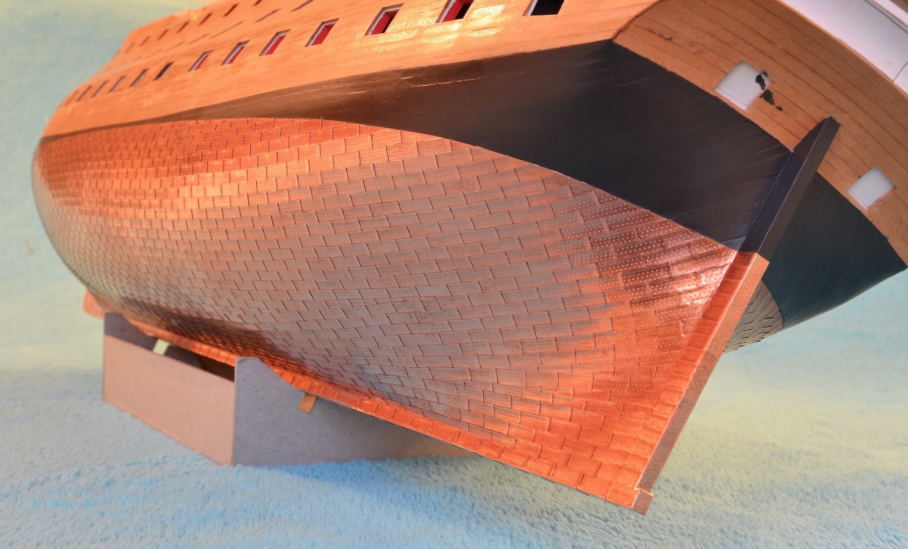
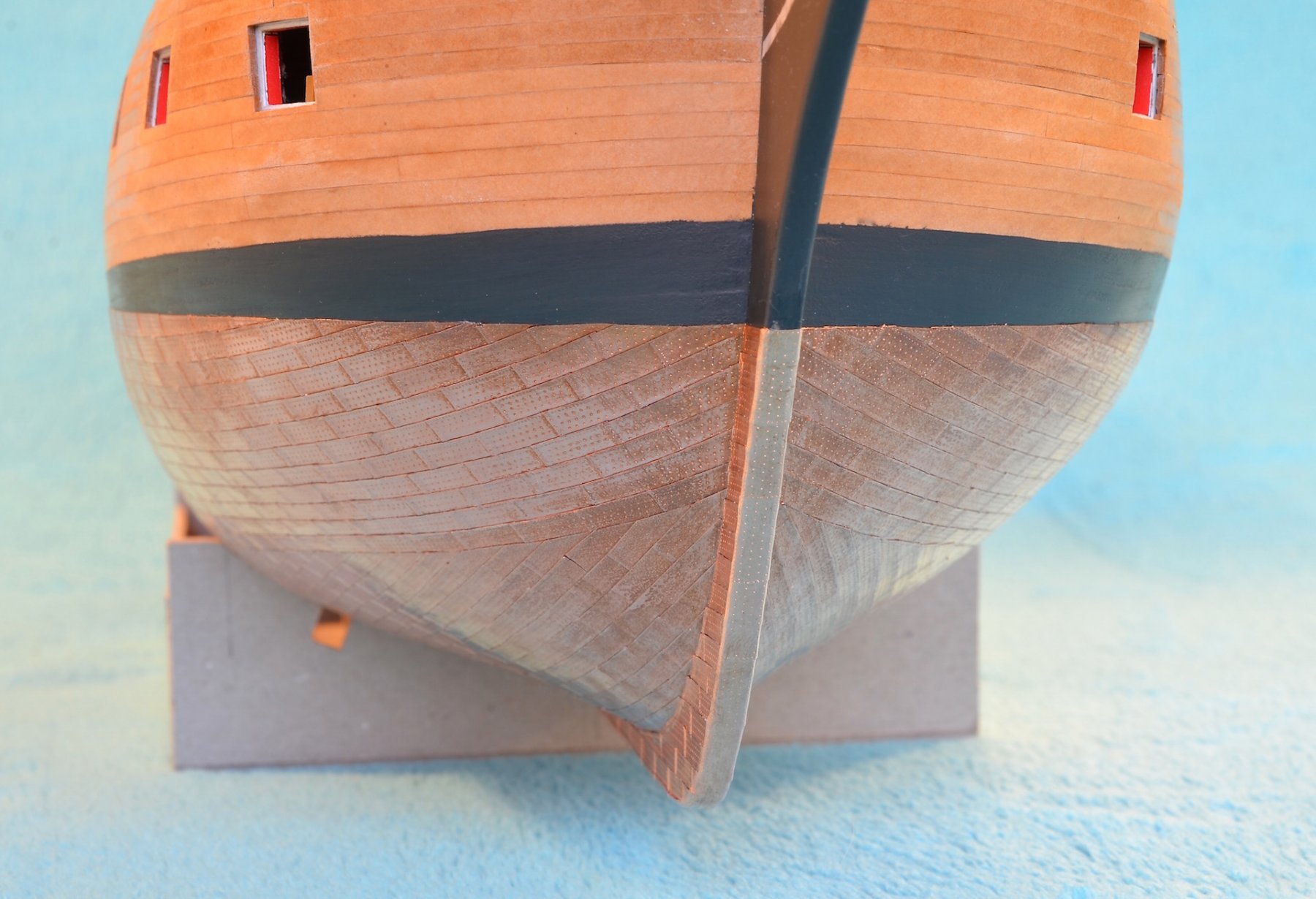
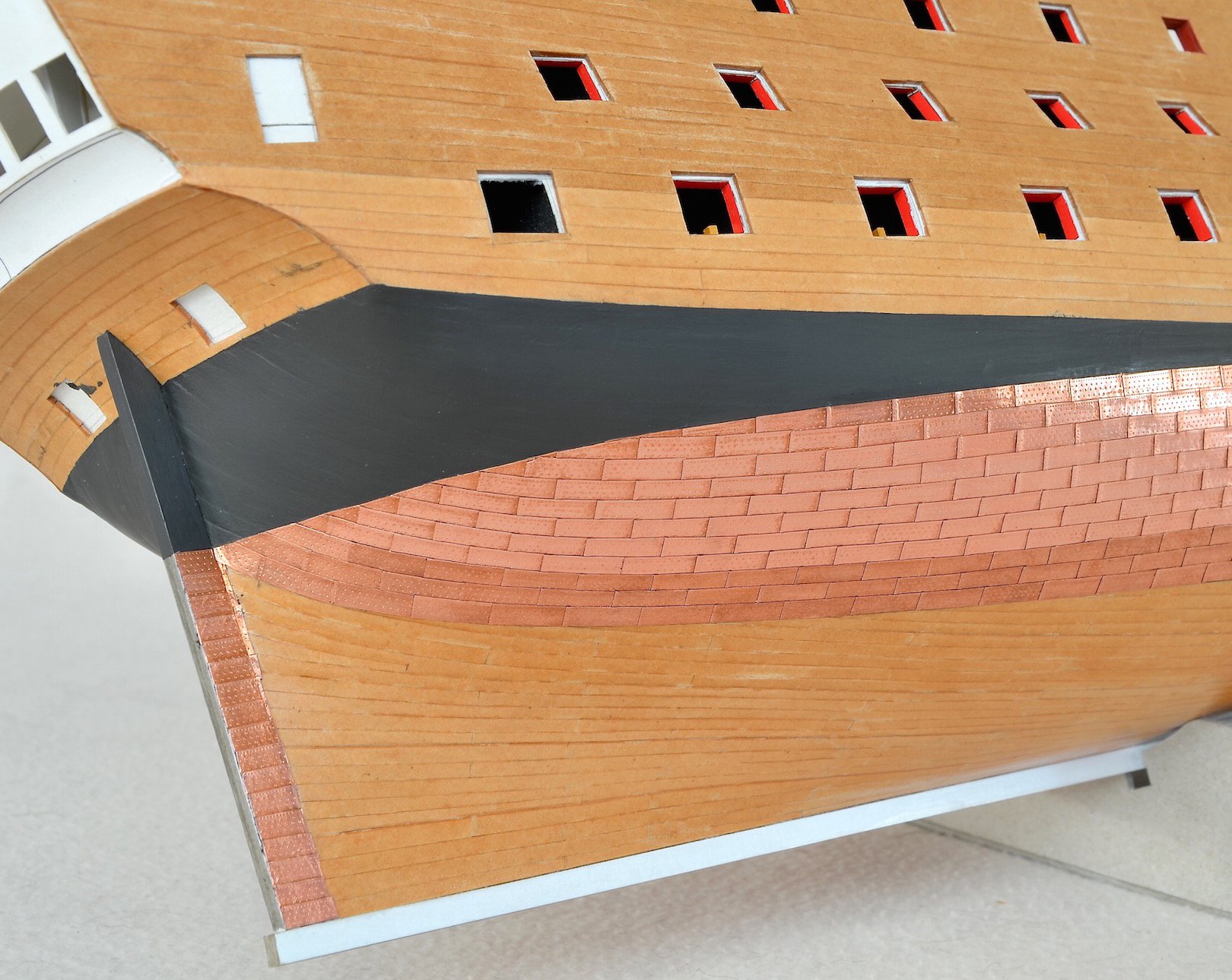
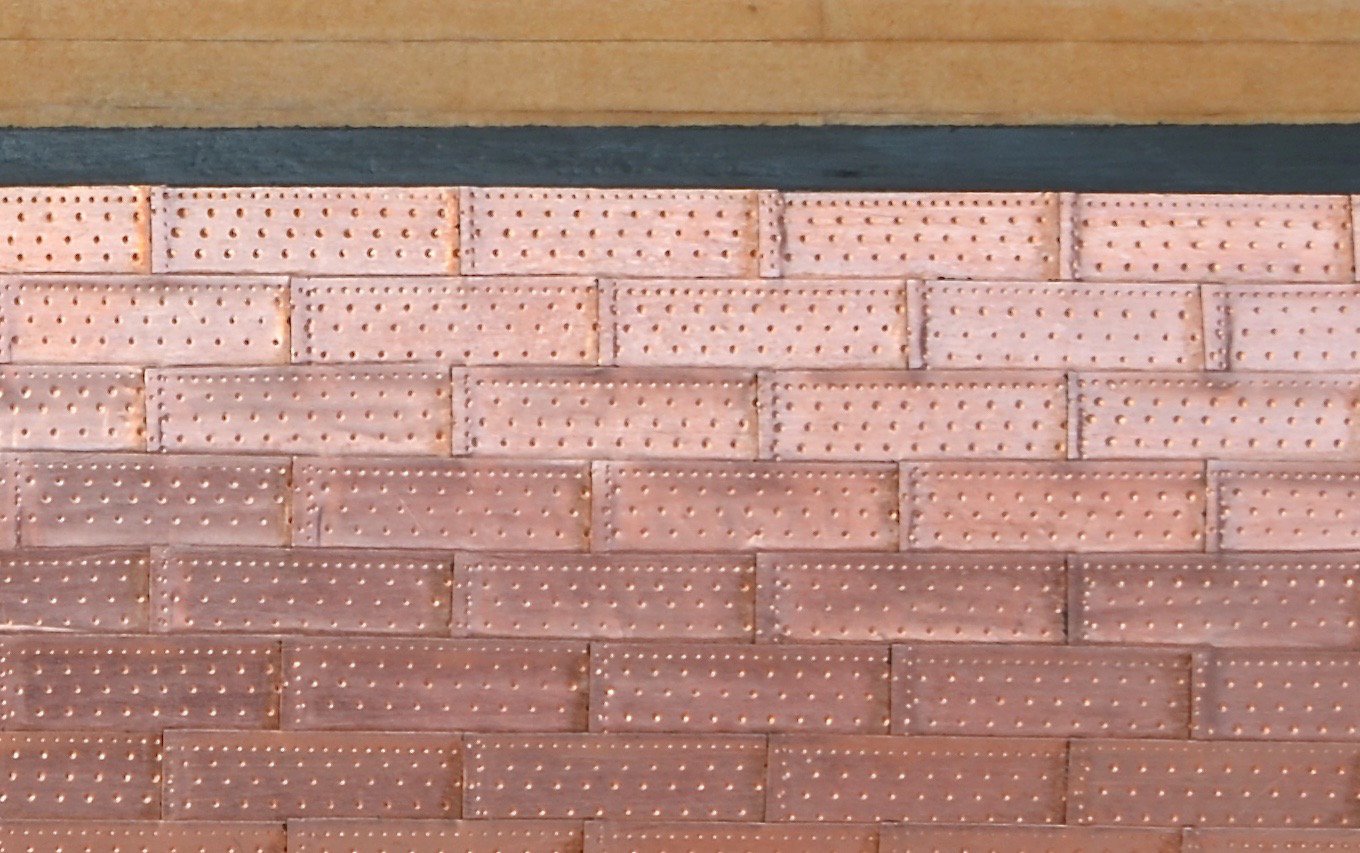
State of works for today.
Copper plates on the port side.
Copper plates on the sterboard (arranged the upper belt of plates).
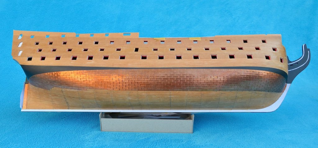
Bow part of the port side.
To arrange each rows of copper plates precisely, I marked their identical course on both sides.
A few stealers need to be laid in the aft part of the ship.
I've made a kind of "shirt" to protect arranged copper surface.
To be continued...
-
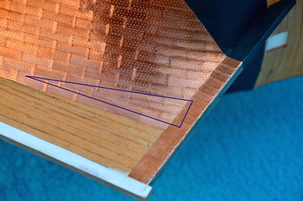
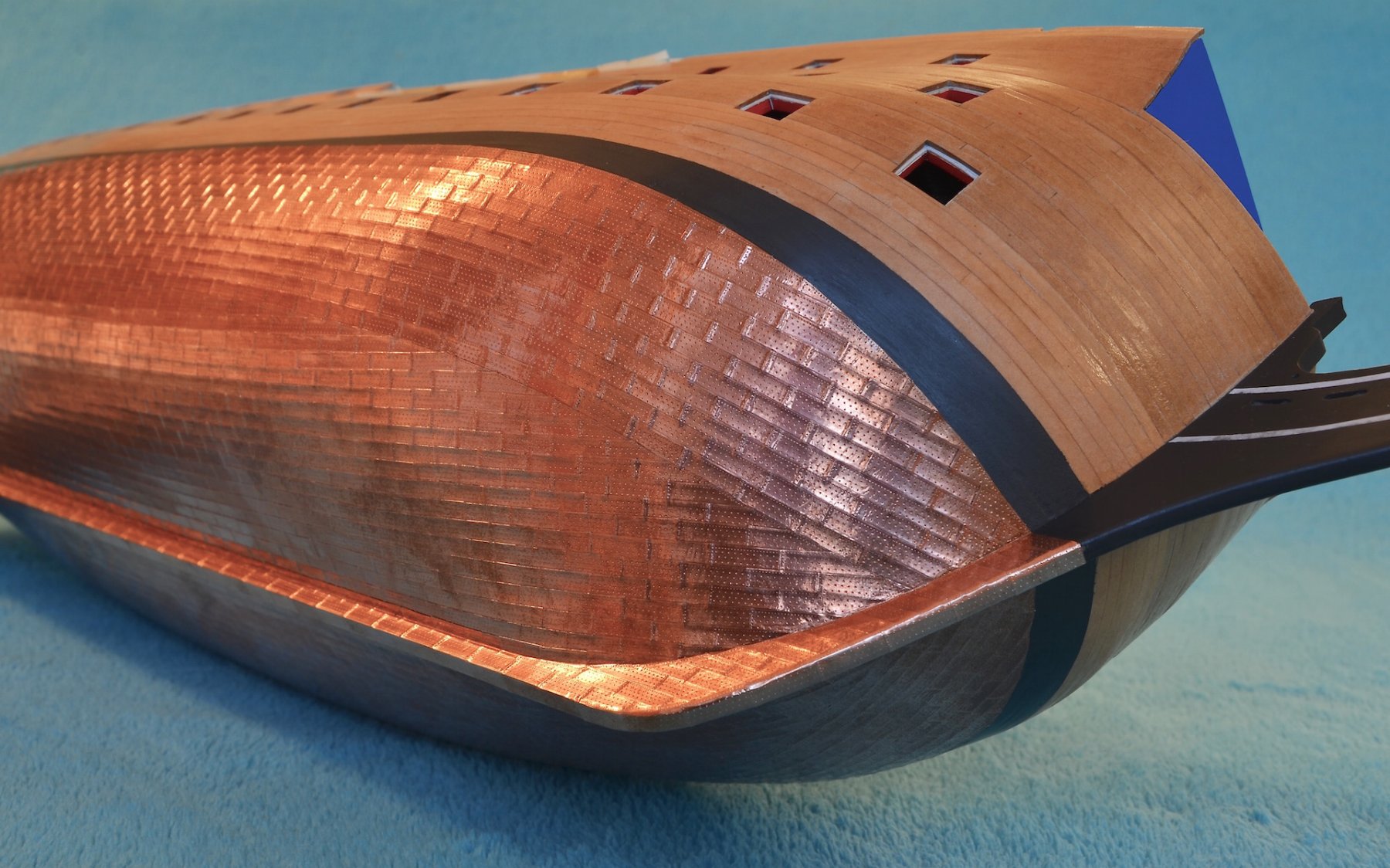
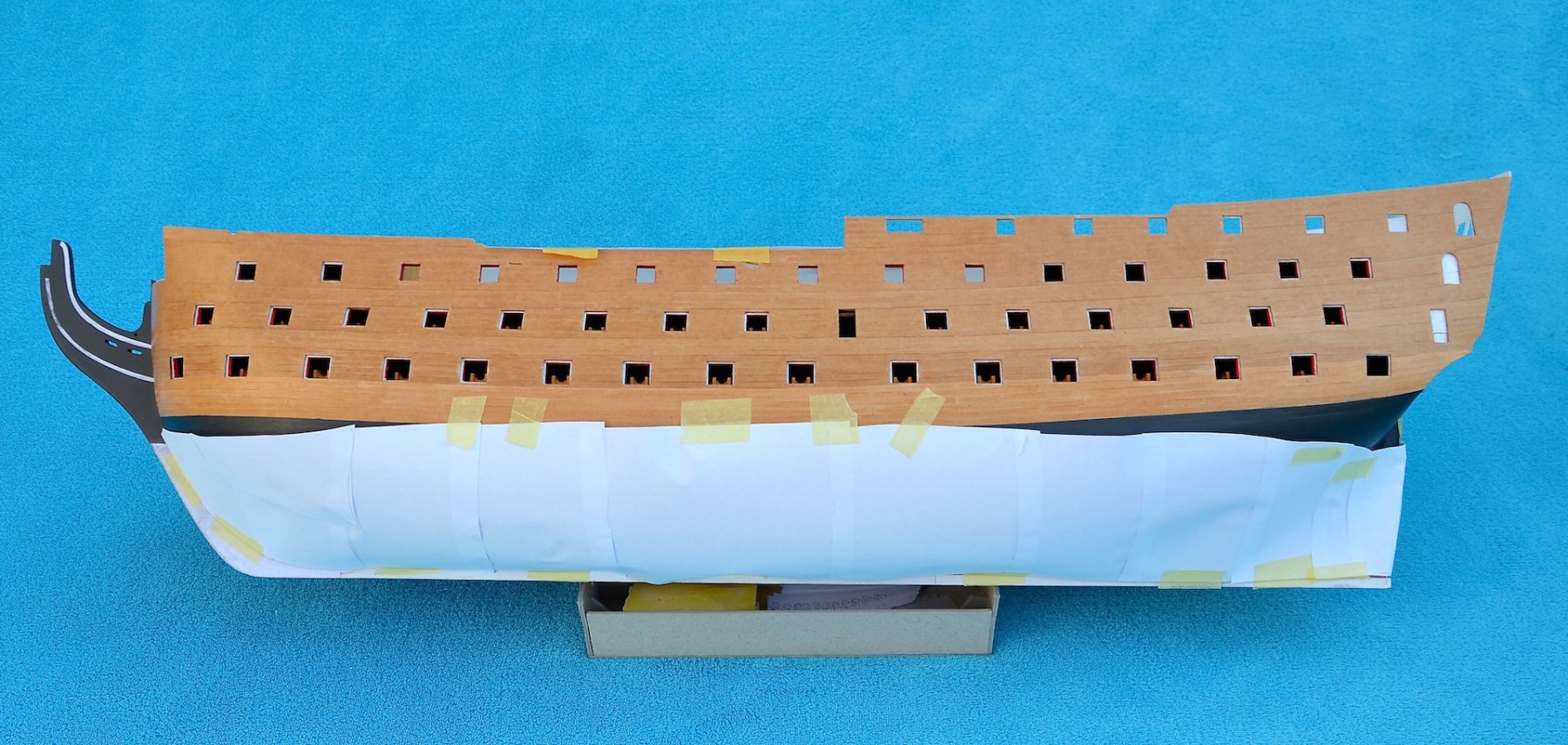
Today, the thing is not about the progress in building, but about why sometimes you need to destroy something to make it good.
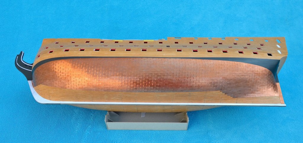
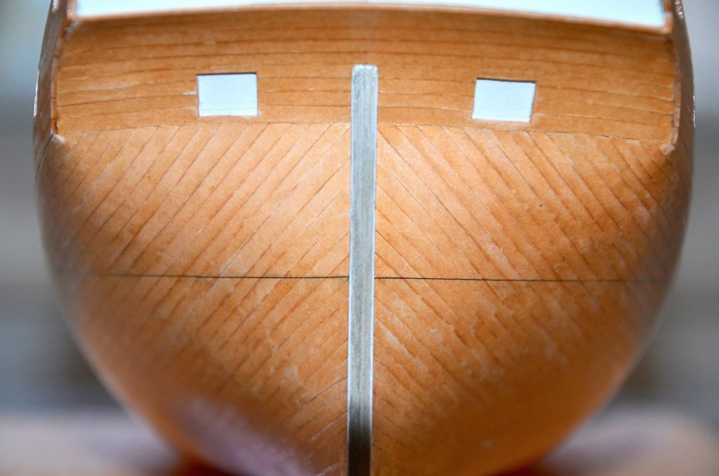
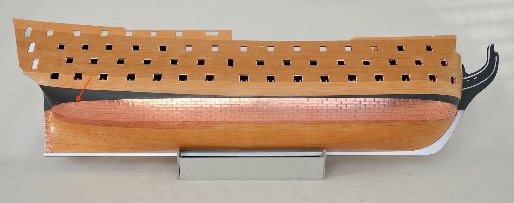
After gluing the plates I realized that I had started laying the copper cover too close to the stern. The copper strips should run here more or less according to the layout of the planks. In the picture below, I marked the correct layout with violet lines.
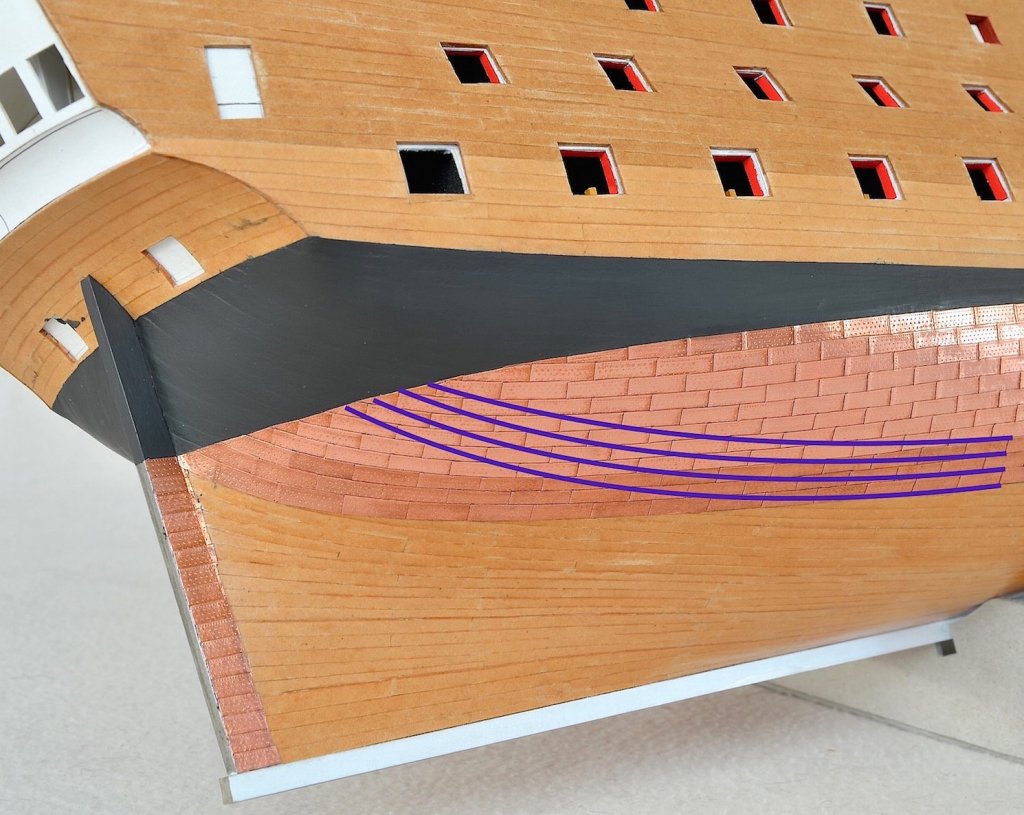
Continuing laying of plates in this way, would cause their improper arrangement on the stern and in the bottom part. In the picture below you can see, that in the central part of the hull there is still enough space for 20 rows of plates, while in the part closer to the stern there is space only for 15 rows of plates. This way of laying would cause, that copper plates in the bottom part, at the keel, would be laid diagonally (lines of navy blue color), despite that they should be parallel (red lines) to keel, like planks.
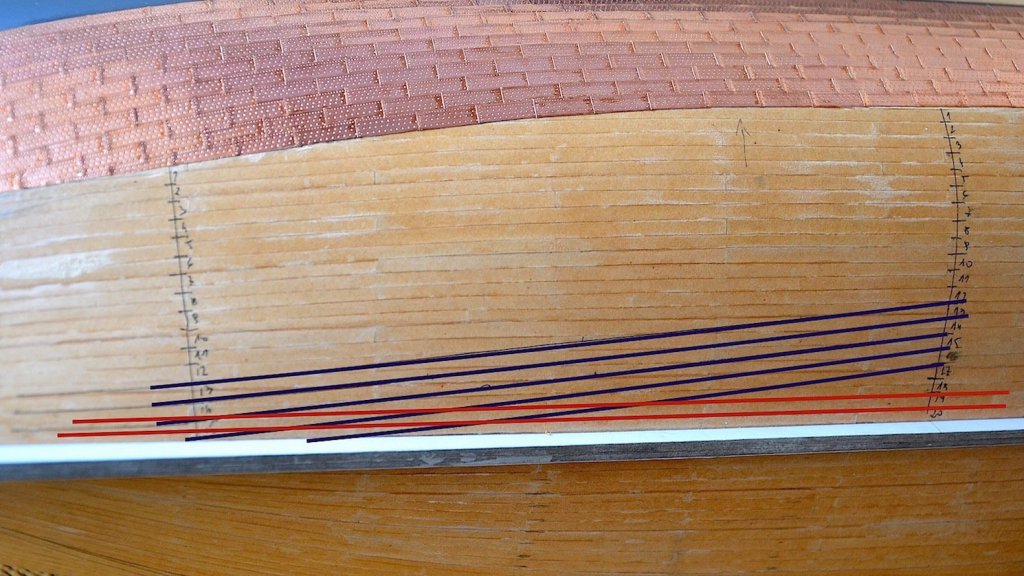
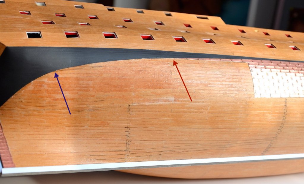
Therefore, I removed a large piece of copper plates (something about 200 pieces) and I'm gonna lay them again. Plates, according to a new calculations (I hope this time correct) I will start to lay from the point marked with a red arrow; I also marked the previous point from which I started laying - using a violet arrow.
To be continued....
-
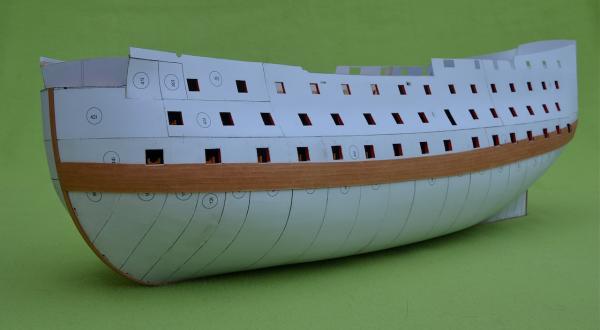
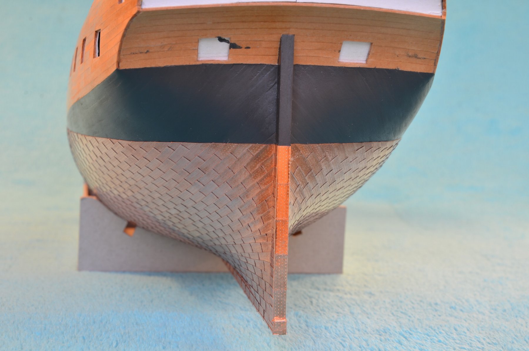
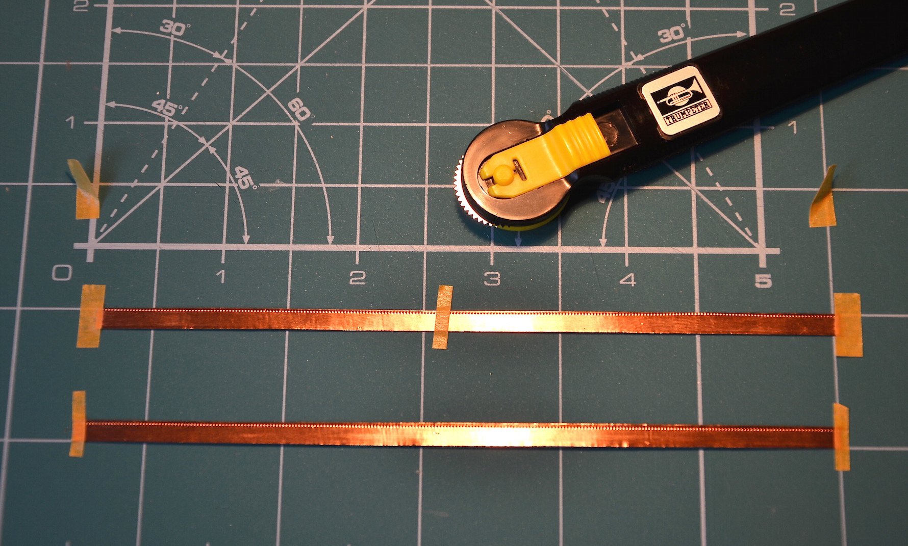
Coppering the hull.
Before coppering, using a highly specialized tool
 , I marked the waterline, which is also the upper border for copper plates.
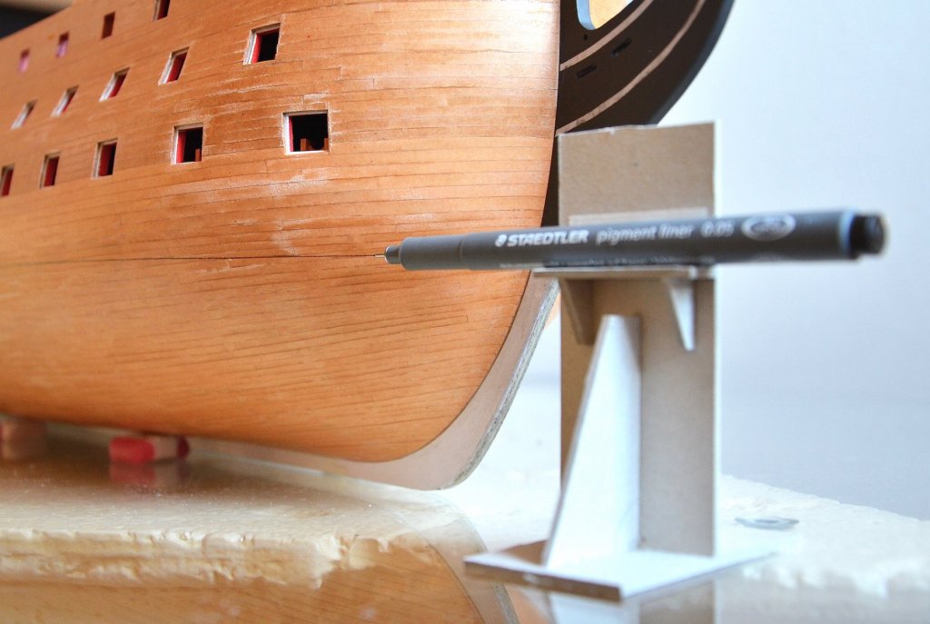
Despite of the primitive method, it goes straight.
The belt between the waterline and the lower border of the main wale (which will be laid in the future) I’ve painted black.
Coppering is made from Ventura Tape copper foil, with black adhesive.
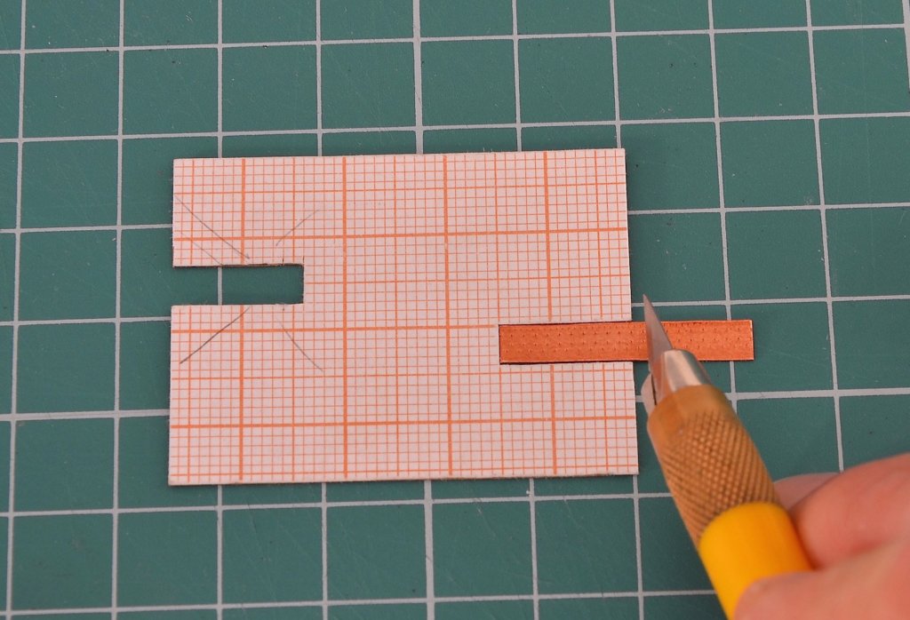
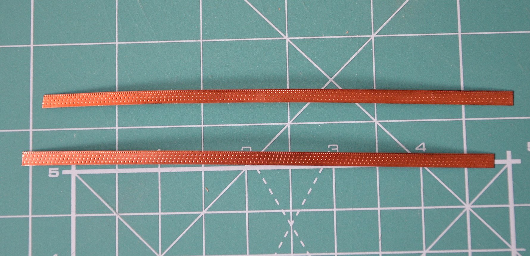
Before cutting the strips imitating copper plates, I fastened a longer strip of copper (about 135 mm) to the cutting mat using a masking tape. Next step was to make an imitation of nailing; I used Trumpeter's rivet maker with densely spaced teeth (by Trumpeter marked with letter „A”) for nailing on the edges, and for nailing in the middle with less frequent teeth (marked as No. „D”).
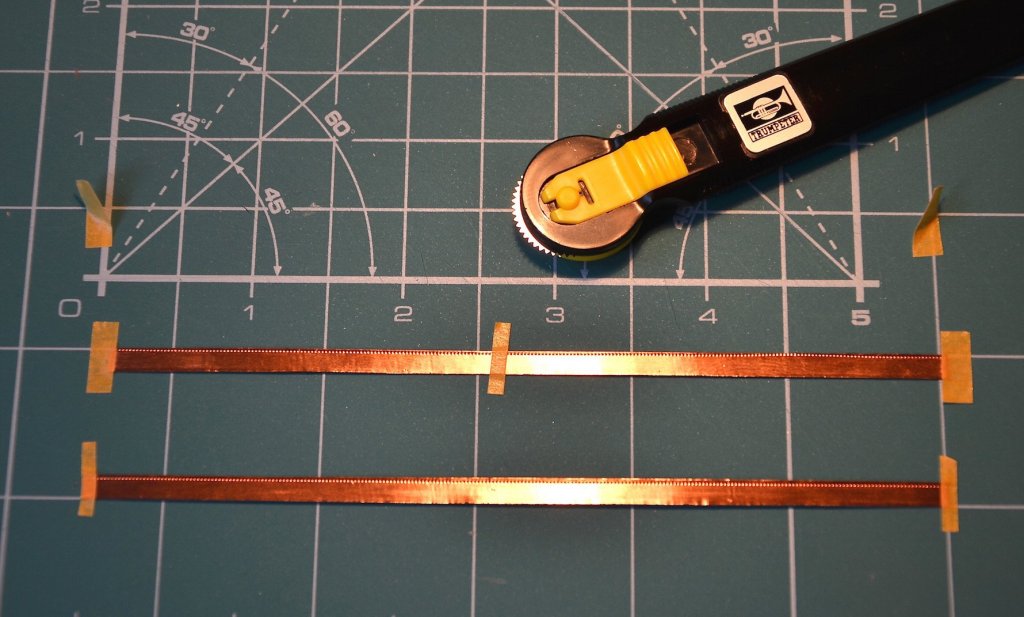

So prepared copper strips I cut - using a small jig – to plates of the correct length, specifically 13 mm.


-
-
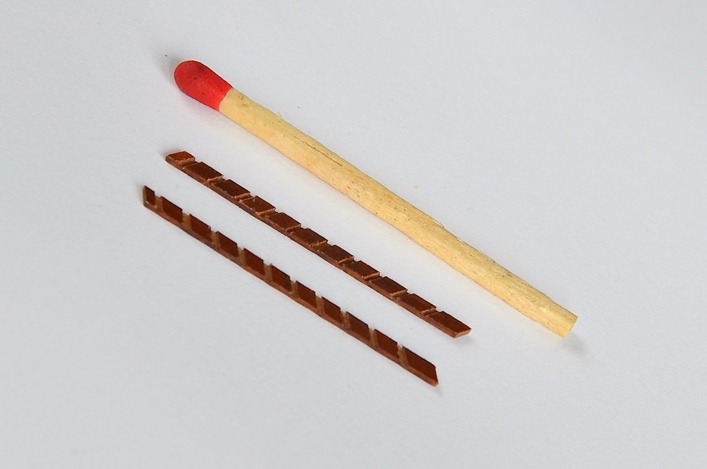
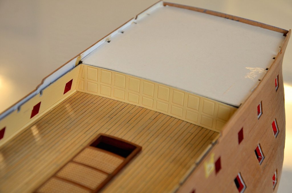
Small update. I've made the ladders, leading from the upper to the middle deck.
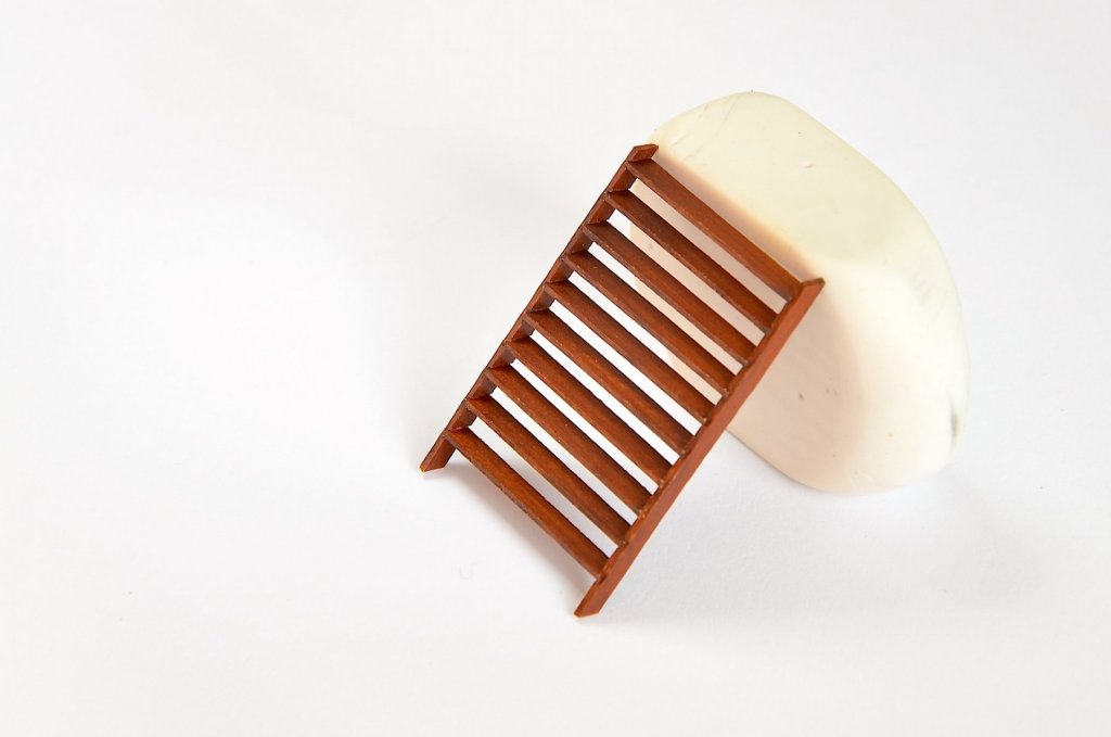
Firstly I'd drawn the cheeks of the ladders, marking them under the appropriate angle (60 degrees), as a mirror image.
Then, I glued croswide the painted straps of the pressboard; I set the distance between the straps by means of a spacer strip, corresponding to the thickness of the step.
After sticking all the horizontal straps a kind of Christmas tree appeared.
Then I cut off the cheeks of the ladders, cutting down on the lines drawn previously; It created a kind of comb with the slots in which I finally glued the steps.
- Altduck, GrandpaPhil, jct and 2 others
-
5
-
-
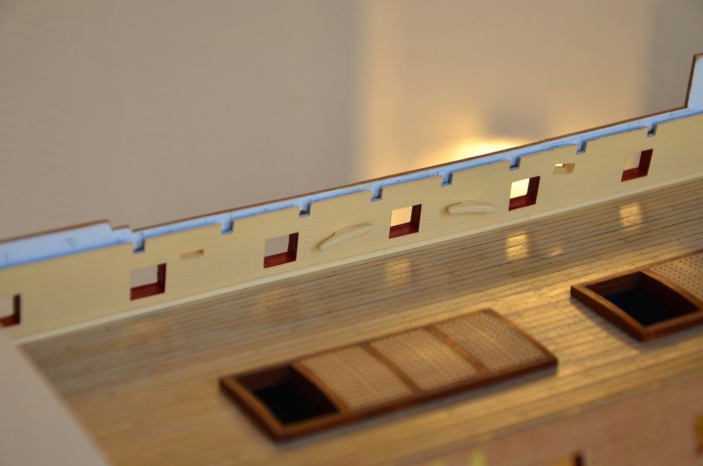
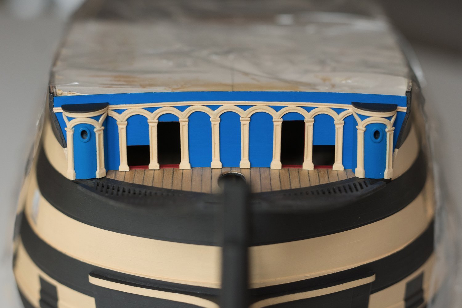
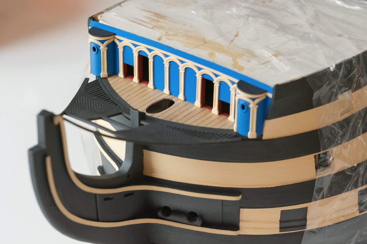
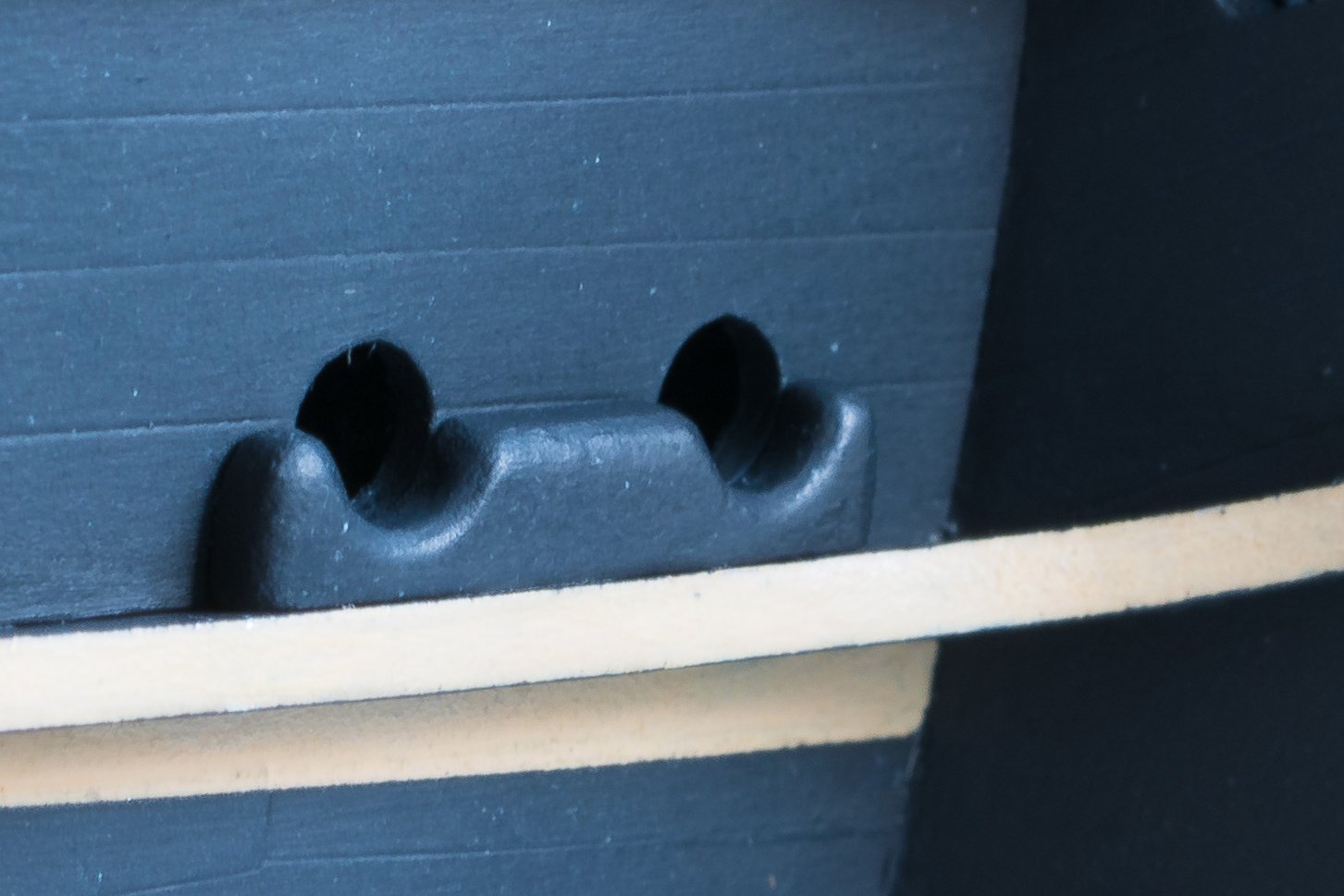
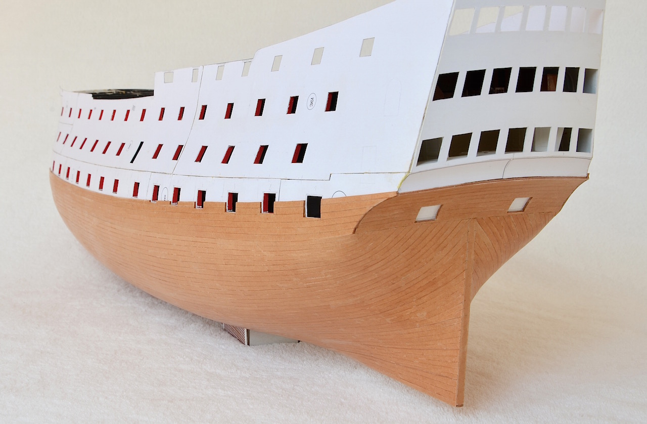
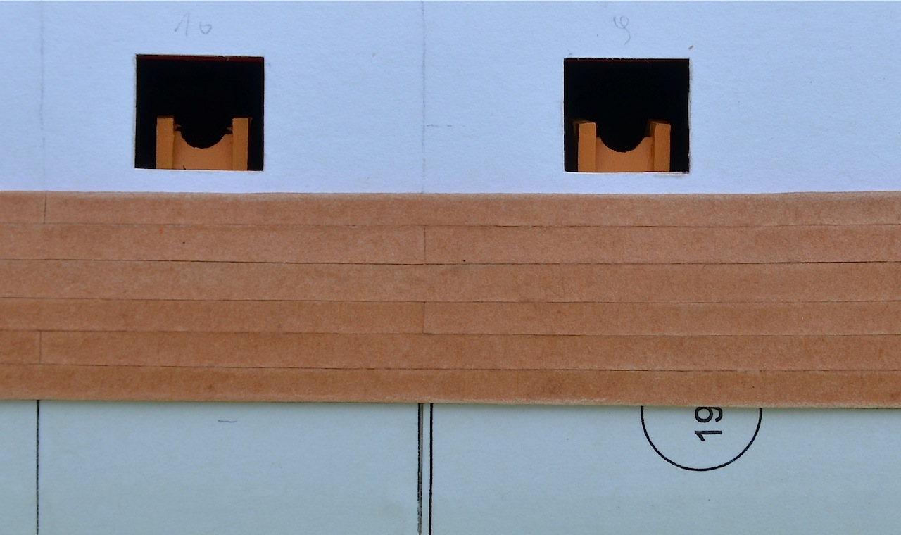
A few photos of my current work. Only several details have been added such as four giant cleats for fore sheets and main tacks and the deck beams. Deck beams are not glued yet; they are just lying. I've decided to change the beakhead bulkhead and lower the door opening and the gunports; this detail was done improperly.


-
Thank all of you for your compliments. Work still goes on, slowly but forward. Soon I'll show some update. The work is dragging like a turtle because there is not enough time to building the model. Additionally I decided to destroy some part of the current work and make corrections. I changed, for example, the look of the beakhead bulkhead and improved the gunports on the upper deck, which after the painting looked ugly.
Modlerbob. Banding card planks is for certain easier than wooden, but cutting them is much more difficult because it’s been done handly. It really hurts
-
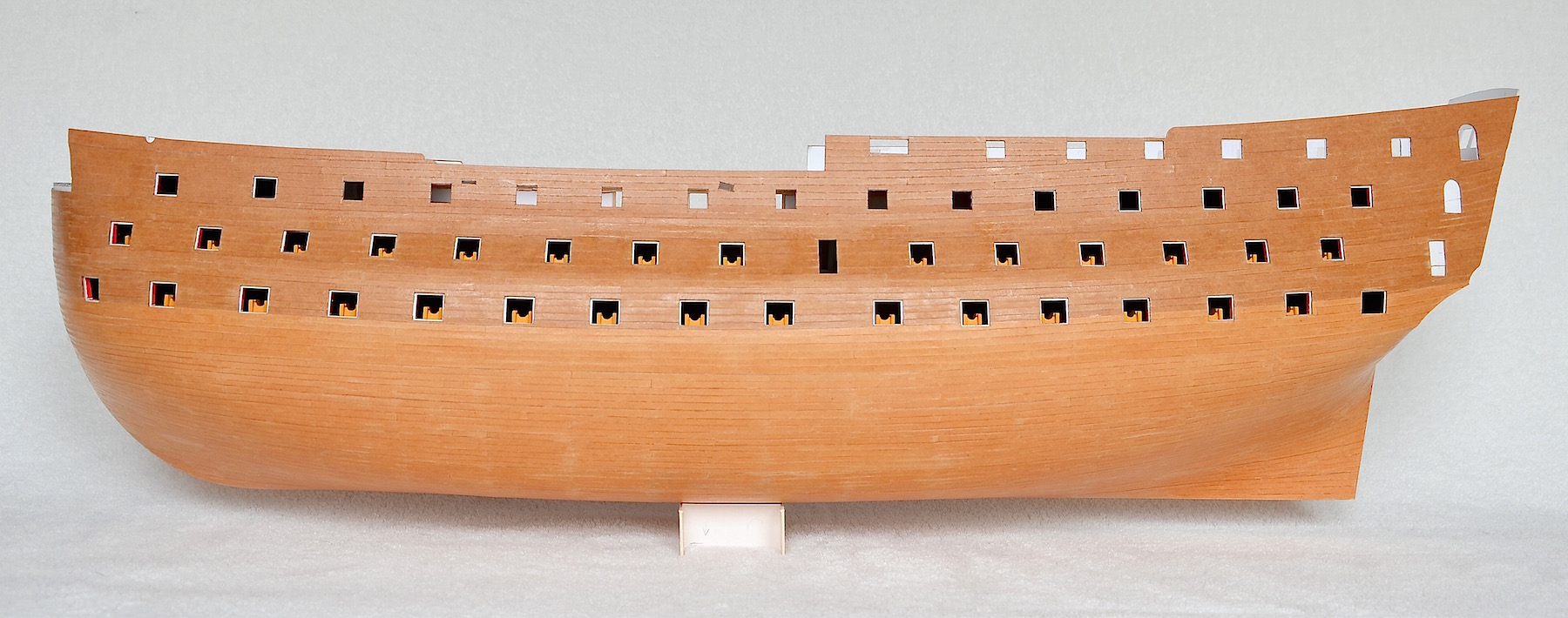
Laying planks came to an end; never again
. I used about 1350 planks of different lengths. 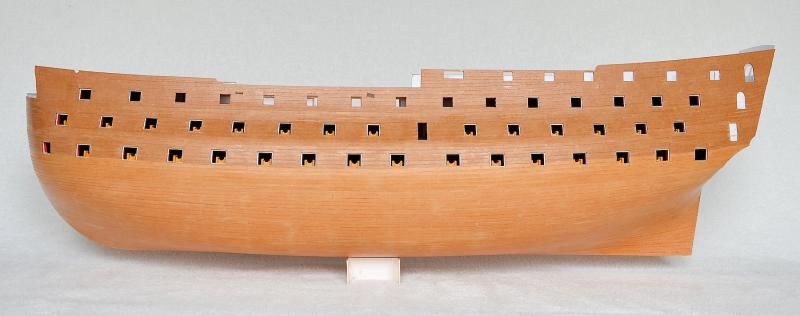

To be continued...
- GrandpaPhil, clearway, dicas and 11 others
-
14
-
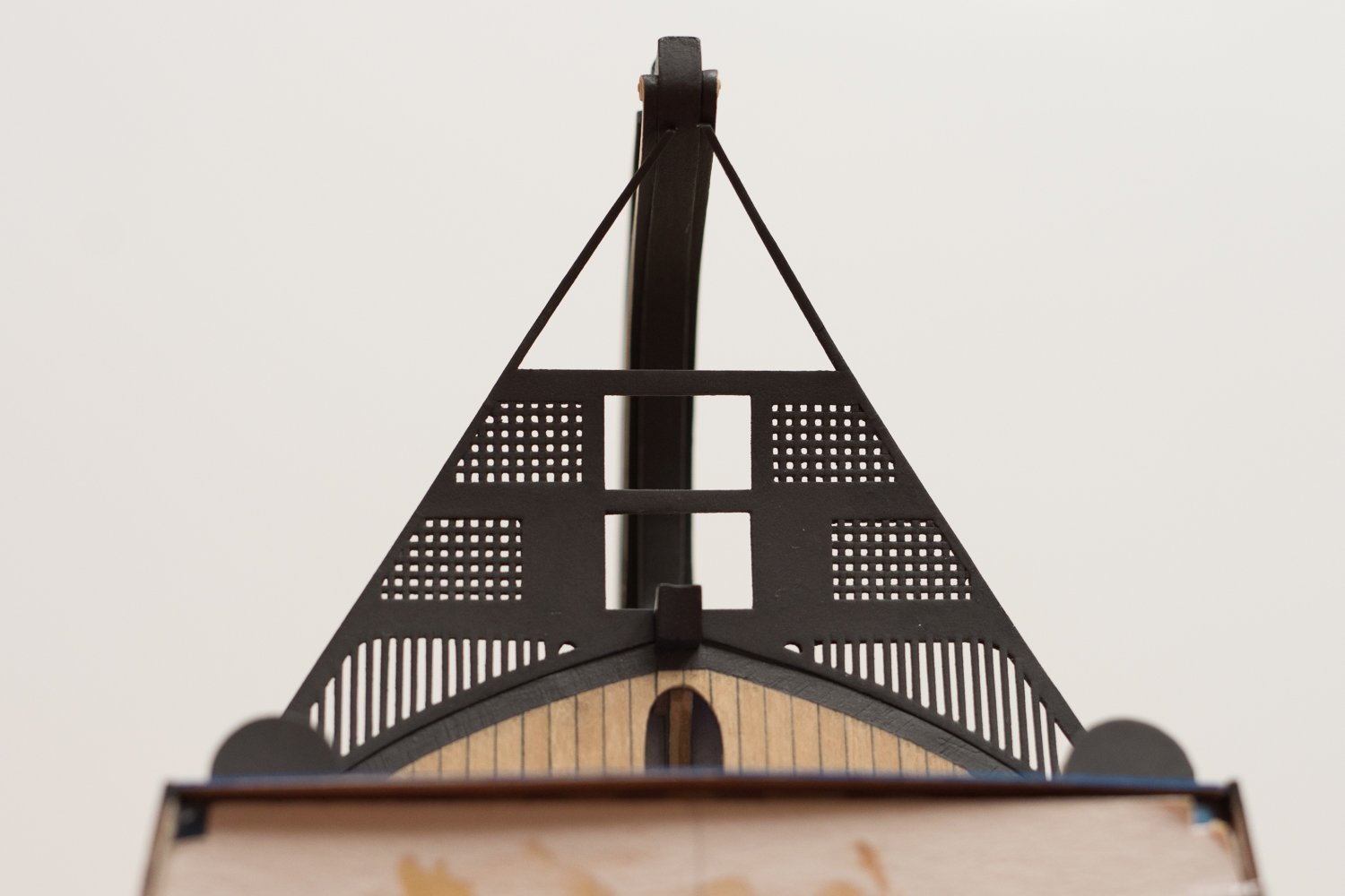
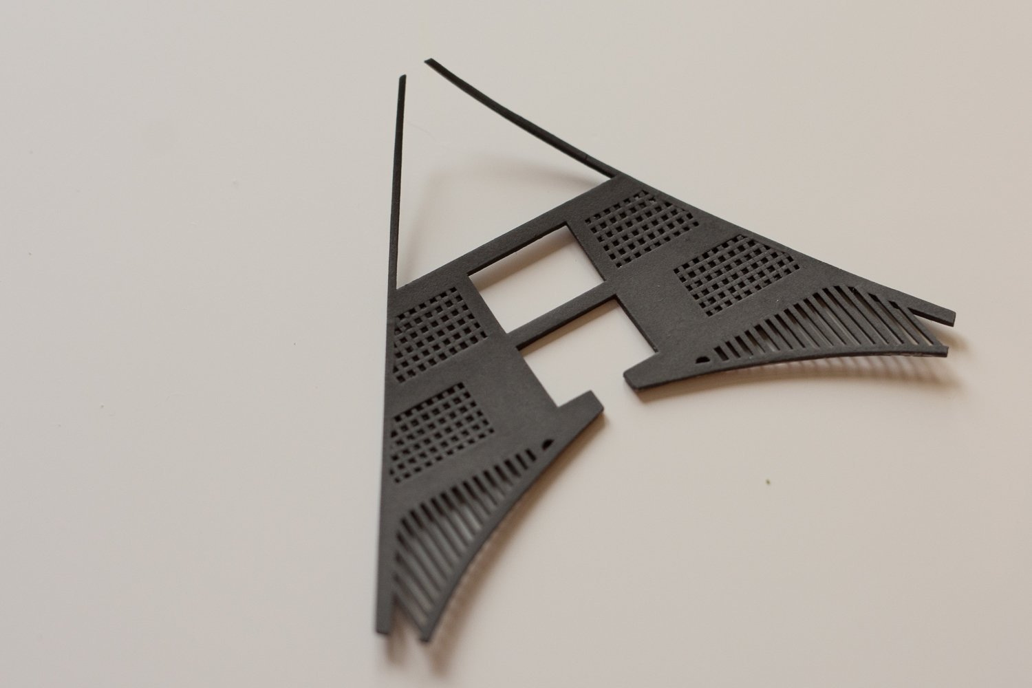
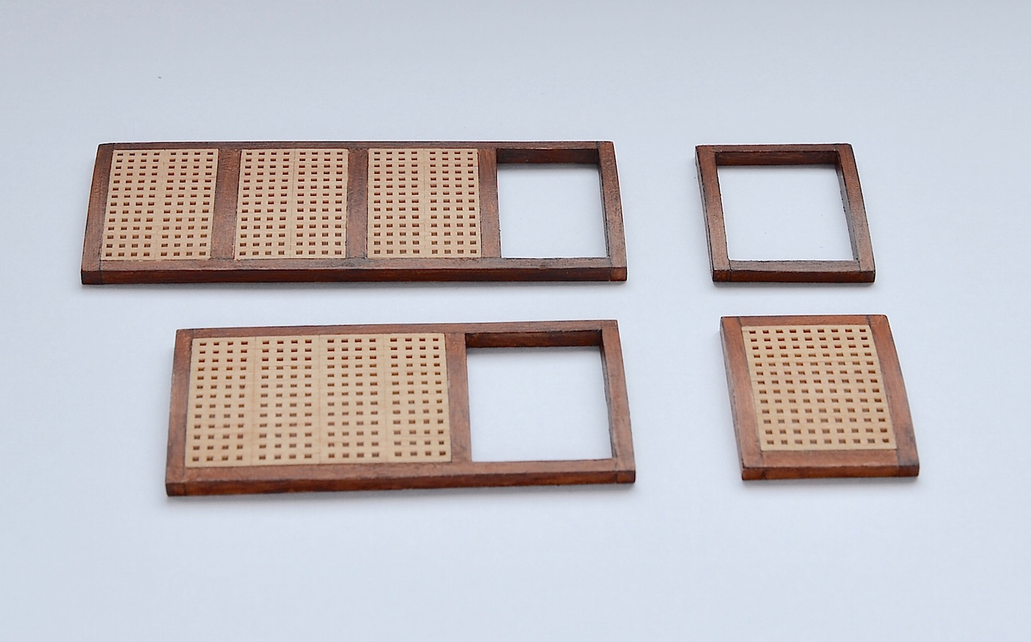
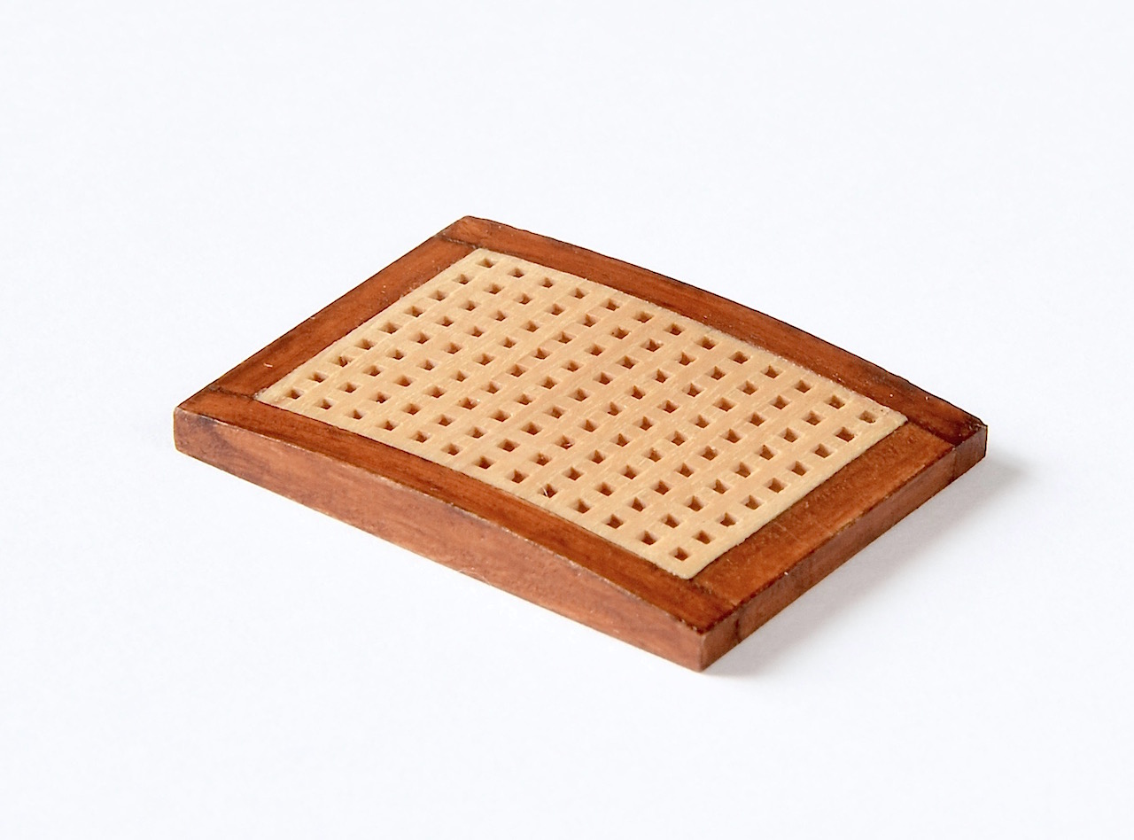
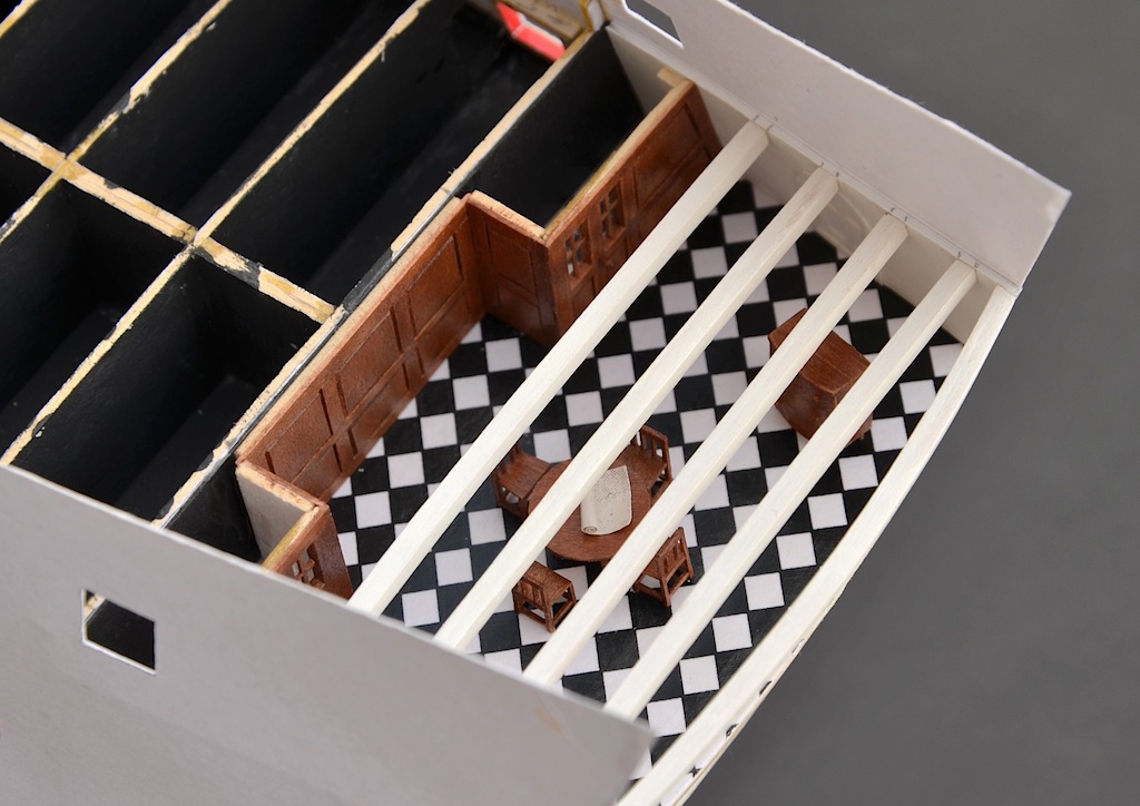
All gratings of the upper deck ...
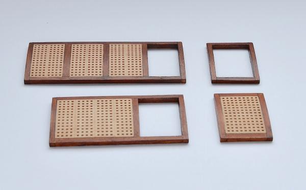
and in the right place on the deck.
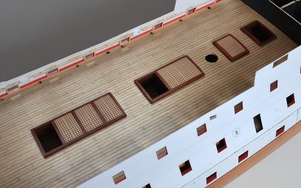
To be continued
- GrandpaPhil, Seventynet, puckotred and 9 others
-
12
-
-
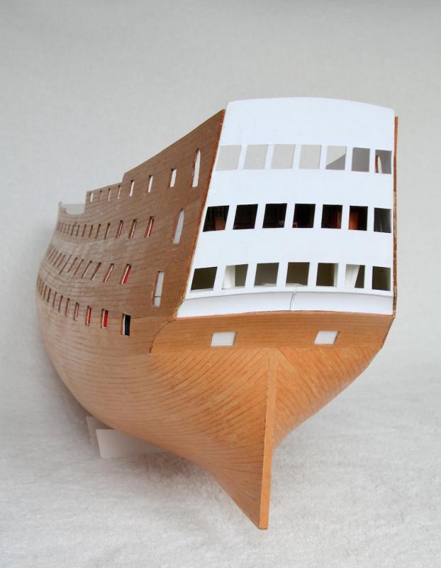
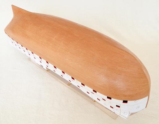
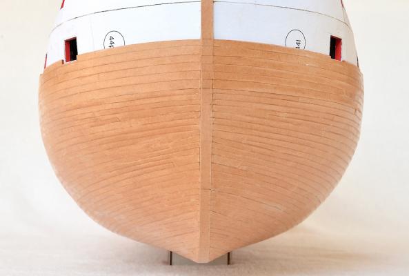
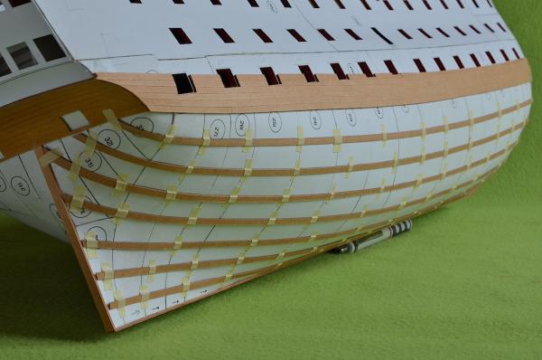
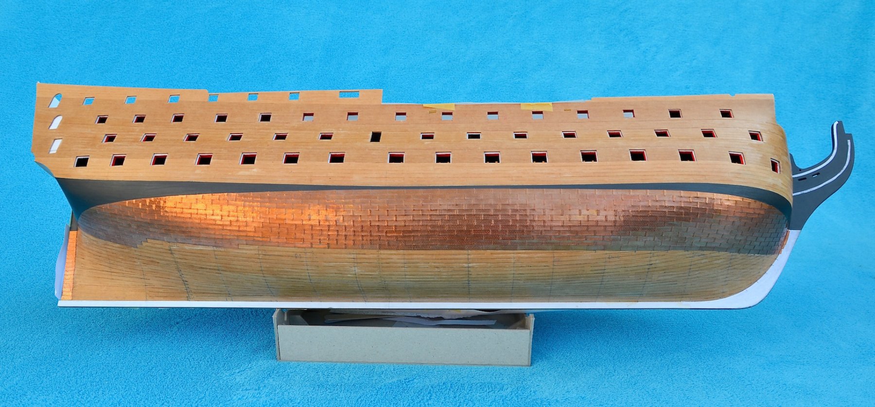
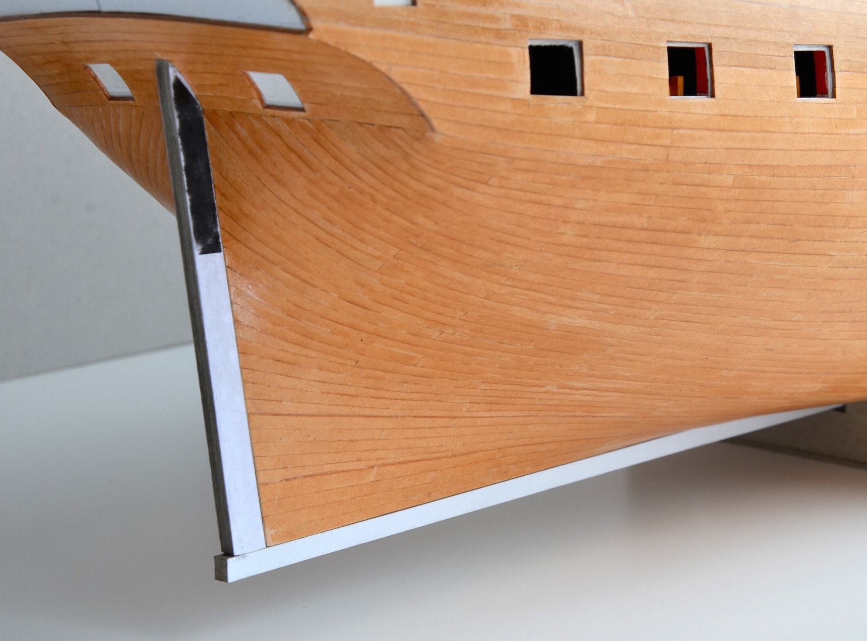
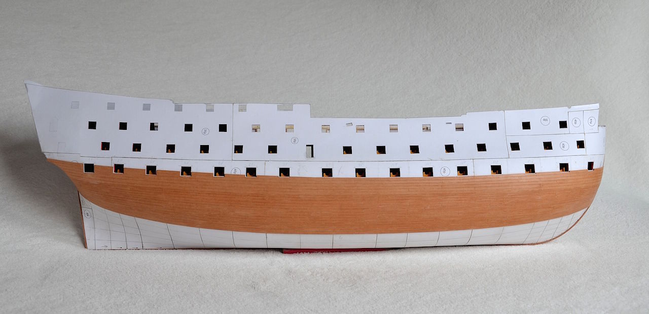
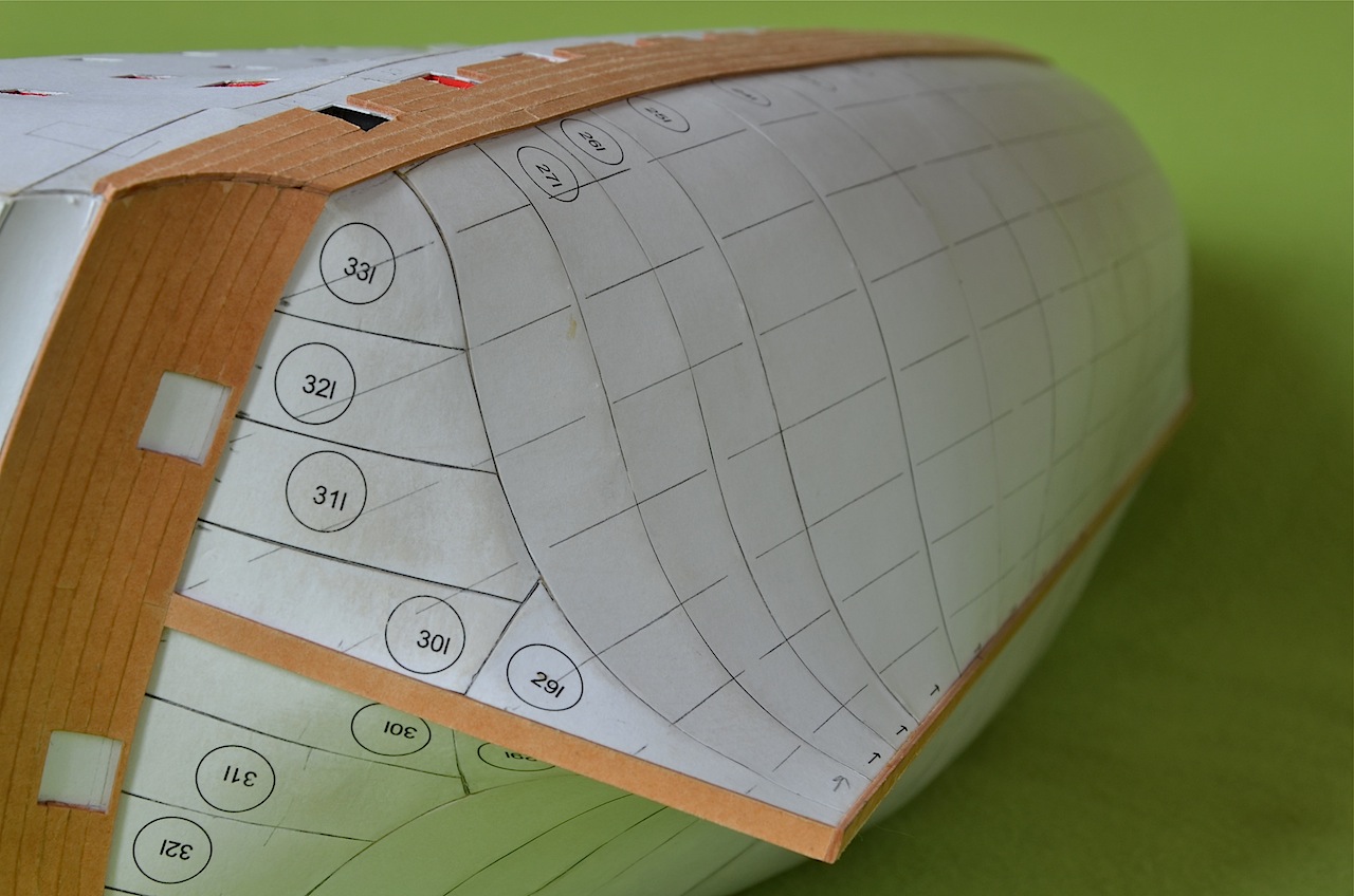
It took me a long time, but the bottom of the hull has been finished. Uff


-
-
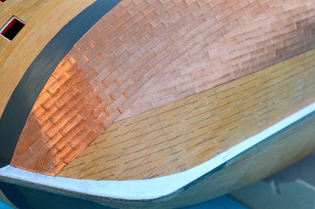
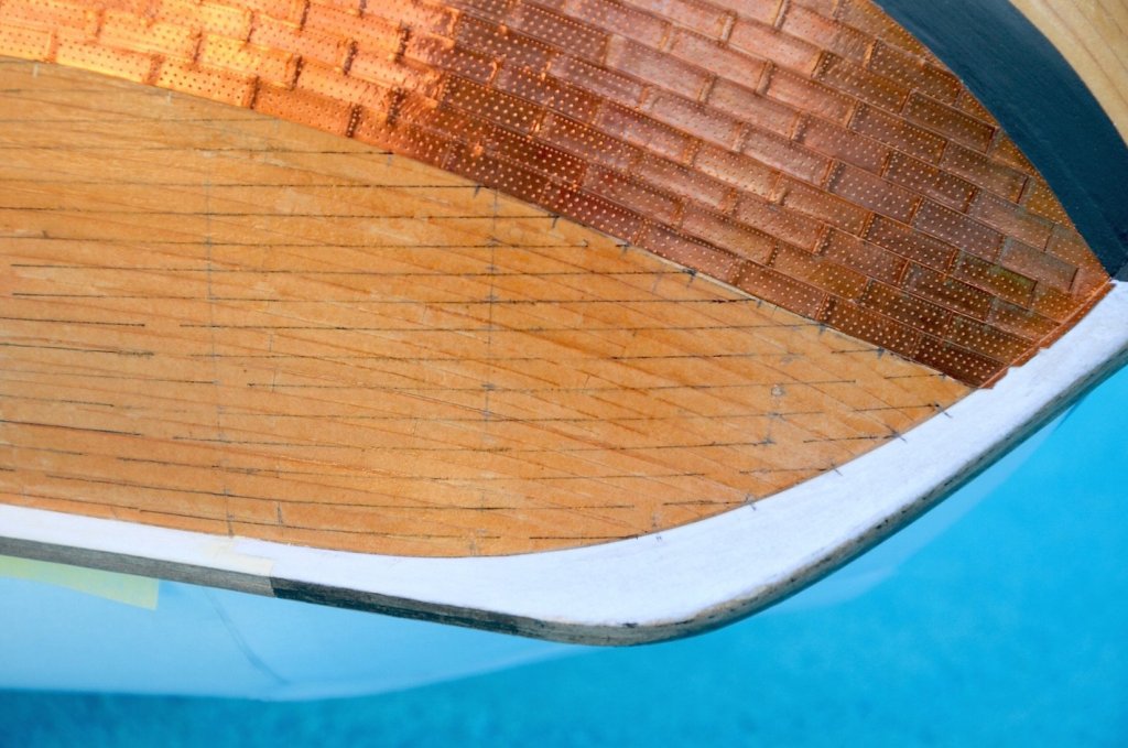
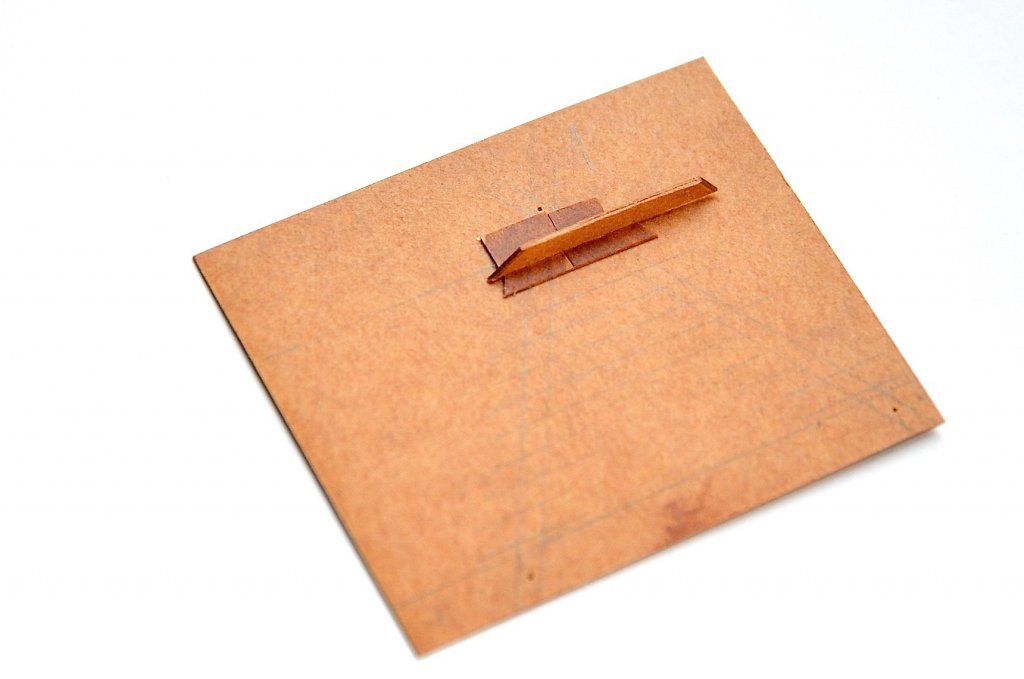
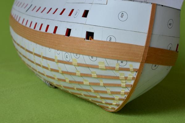
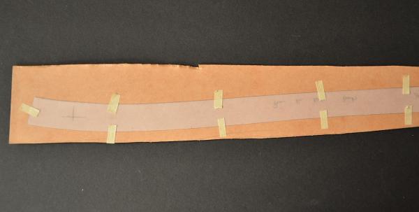
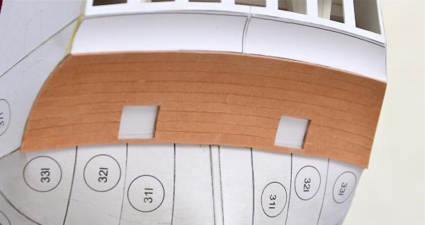
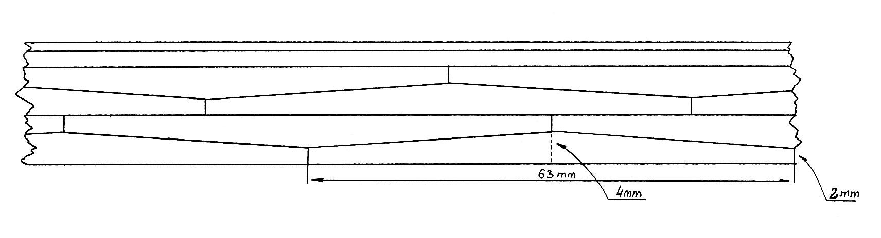
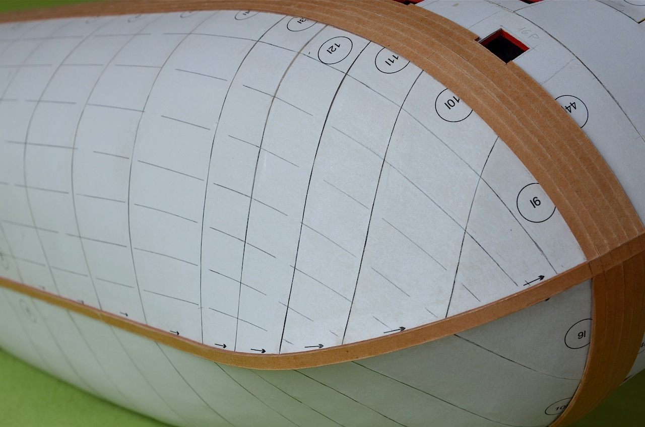
Today's soap opera episode is about my way of marking planks on the ship's bottom. As the first step, a frame the longest in the circuit (a distance calculated from the lower edge of main wale to the keel) had been divided to 7 equal portions, each of 15 mm width. The last eighth section is about 12 mm width.
Then, using masking tape, I fixed temporarily the battens to the hull. The first batten was fixed 15 mm below main wale, the second 30 mm beneath main wale, the third 45 mm etc. After laying all the battens, I marked them on the hull with a pencil. After that I removed all the battens. This way I got eight long belts. Each of these belts will be first copied on tracin paper, then on the pressboard and finally the pressboard will be cut into single planks.
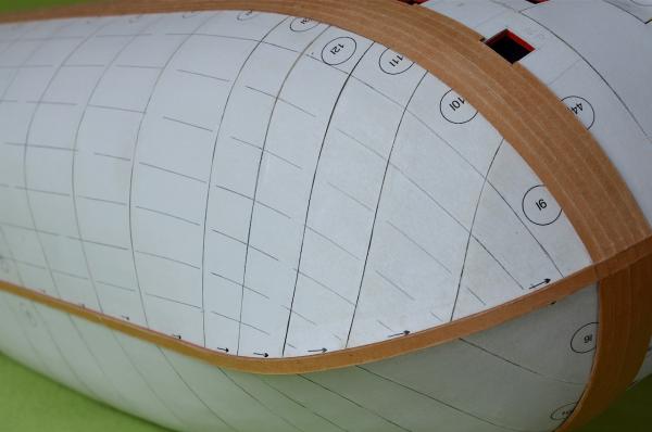
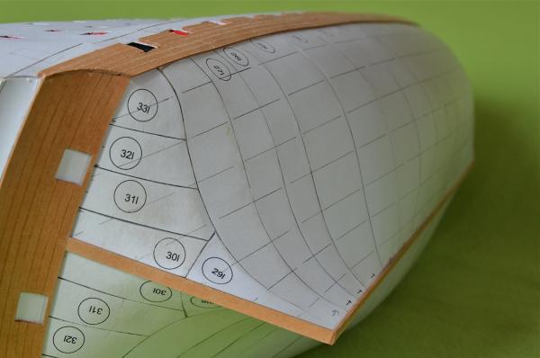
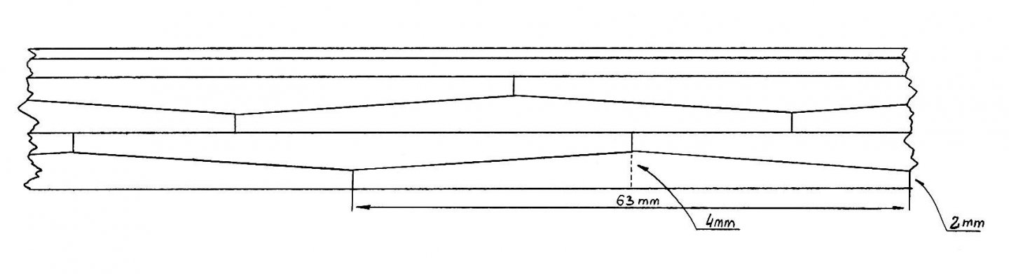
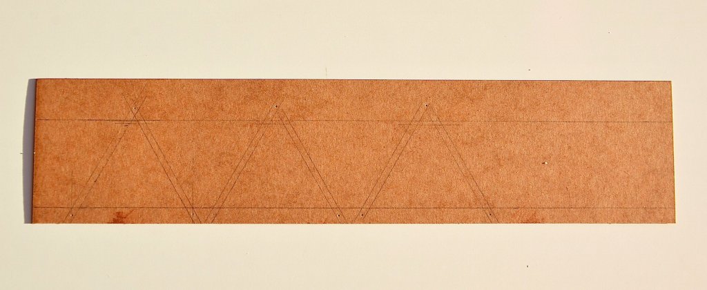
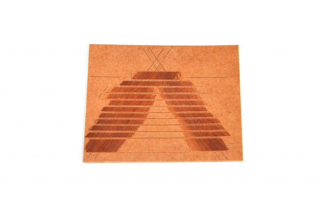
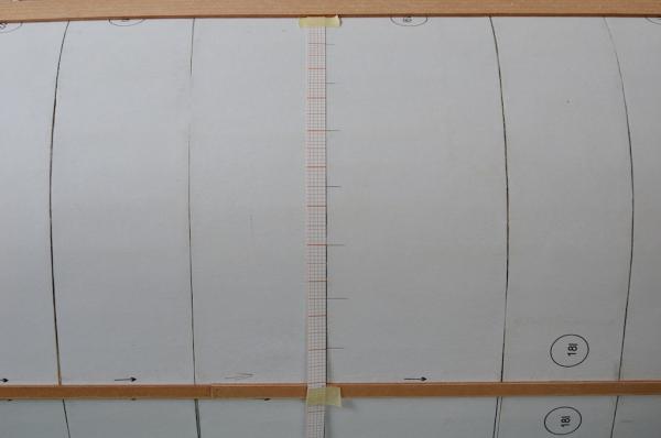
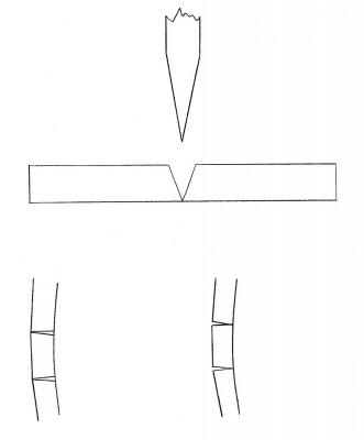
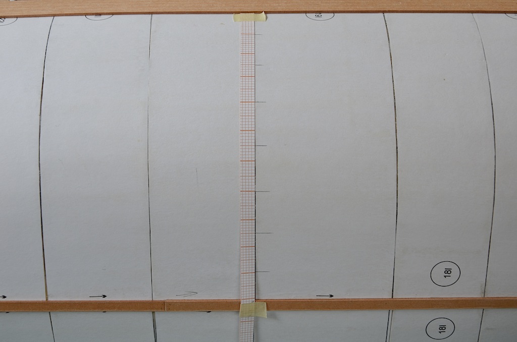
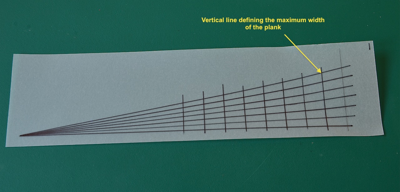
Now a few words about how I share the long belts into single planks. For this I use the pattern shown below. The vertical line on the right side, shows the maximum width of the plank that is needed.
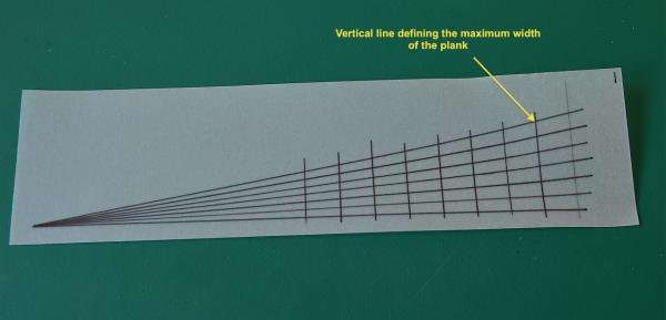
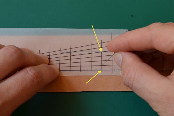
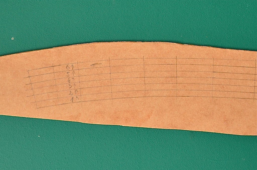
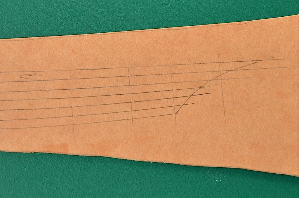
The first thing is to put the triangular pattern onto the belt, previously drawn on the pressboard, so that the bottom edge of the belt come together the lowest, horizontal line of the triangular pattern. The second step is to move the pattern to the left or right, until the top edge of the belt will cross with the upper diagonal line of the pattern (the contact points are indicated by the arrows). The third is to mark the points in these spots, where diagonal lines crosses with the vertical line. So I follow until the end of belt. At these points where the belt is narrow (for example closer to the bow), the narrower part of the triangular pattern is put on the belt. In this way it is possible to smoothly taper single planks from their largest to the smallest width.
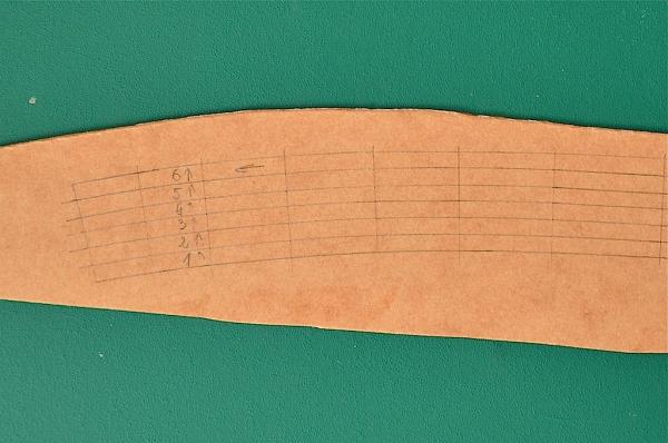
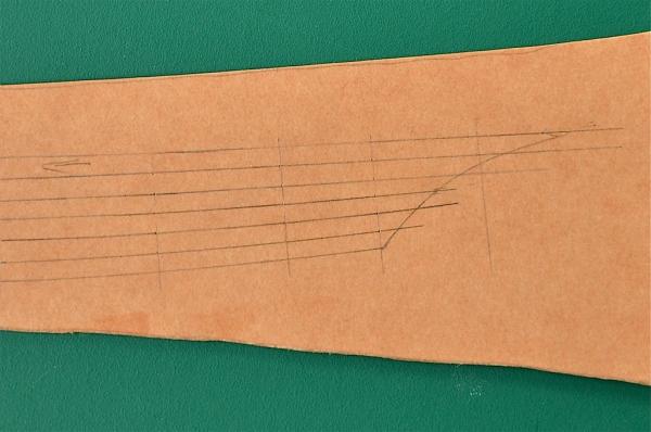
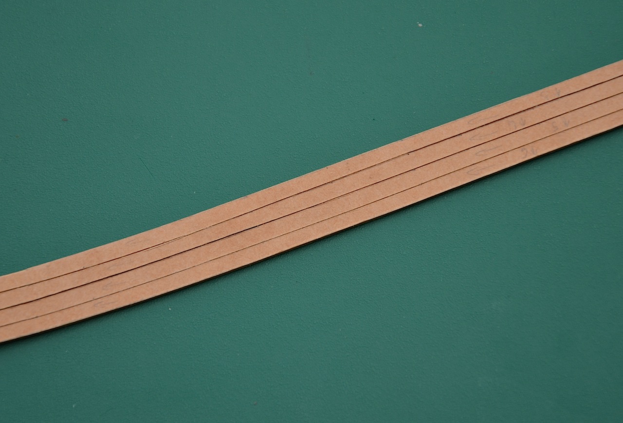
Finally I join the points marked on the pressboard.
To be continued...
- puckotred, etubino, justsayrow and 10 others
-
13
-
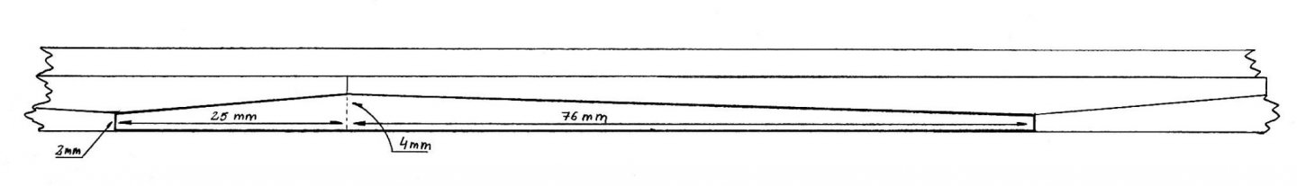
I’ve started laying planks on the sides. As a first step I’d set on the sides the lower edge of the main wale. Next, using tracing paper, I made a pattern corresponding to the shape of the main wale. Then I temporarily glued the pattern to the pressboard, which may seem a bit strange, from the inside of the pressboard, i.e. this side which is glued to the hull. Then I copied a shape of the main wale onto the pressboard and cut pressboard into single planks.
Now a few words about why I’m cutting the planks from the inside. Typically, the paper is cut from the outside, i.e. from the side visible after gluing the element. This time, leading the blade from the inside I’m doing this because of the shape of the blade and the tendency to "extend" the thick pressboard during cutting. The blade, as is well known, has a conical shape. When a pressboard is cut with a knife, in particularly pressboard having a thickness of at least 1 mm, a V-shape slot is forming between the cut edges. The slot on the upper surface of the cut pressboard is wider than at the bottom (upper drawing). When such planks are laid on the sides, the wider part of the gap is placed on the inner side (this glued to the hull) and due to the oval shape of the hull, internal, diagonal cutting edges of the planks, joins together almost without leaving a space between them. What is important, the wider part of a gap is not visible on the outside (this illustrates lower left drawing). If the pressboard were cut from the outside, on the sides would be visible V-shape gaps (smaller or larger). This shows lower right drawing.

To be continued...
-
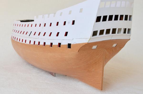
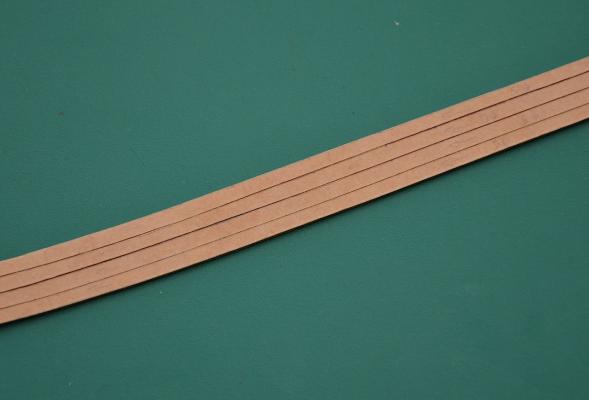
I've started laying the proper planks. It will be entirely made of pressboard, thickness 1 mm, cut into 3 mm strips, imitating planks. Cutting pressboard with a knife is a real nightmare, because it is as hard as wood.
To be continued...
- puckotred, etubino, Captain Slog and 7 others
-
10
-
Huh ... real SF
Nenad. I can assure you that it is quite real. There is nothing extraordinary.
-


Pt. IV: Tools & Other Supplies
in Card and Paper Models
Posted · Edited by Paragraf
Chris, thank you very much for your posts that popularize cardboard modeling.
When it comes to tools used in cardboard modeling, biopsy punches are very helpful. These are very sharp surgical instruments, suitable for cutting very small holes (1 mm, 2 mm). https://medicaldepot.pl/sprzet-medyczny/chirurgia/materialy-biopsyjne/sztanca-biopsyjna-z-suwakiem-1-mm-383245742.html.
For modeling oval elements made of cardboard, e.g. for forming engine covers in aircrafts, such a tool is also used https://thecakes.pl/pl/akcesoria-do-modelowania/2611-zestaw-narzedzi-do-modelowania-kwiatow-z-masy-cukrowej-4-szt.html. Basically, it is used in confectionery, for modeling sugar mass but in card modeling is also very useful.