


Jond
-
Posts
877 -
Joined
-
Last visited
Content Type
Profiles
Forums
Gallery
Events
Posts posted by Jond
-
-
Post 5
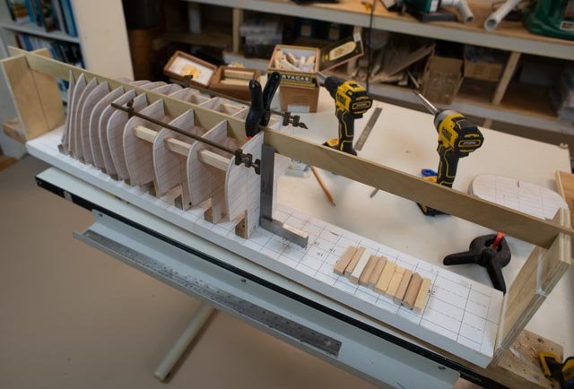
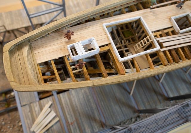
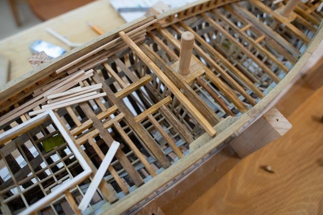
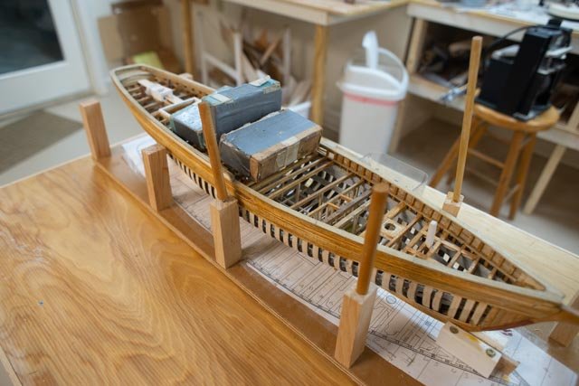
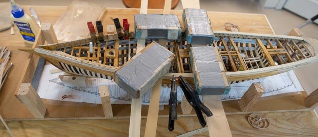
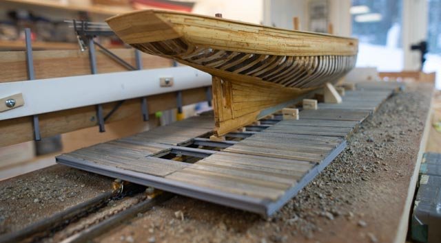
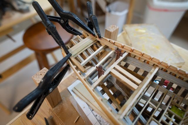
Update on resizing and building the stern.
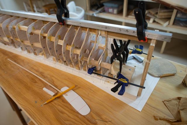
I realized that to properly build the stern I needed to extend the building board. One advantage of this large scale and the stability of the bulkheads is that I saw no movement when I released the aft keel end post. I simply inserted a scrap piece of pine the same thickness and reset the end post.
-
33
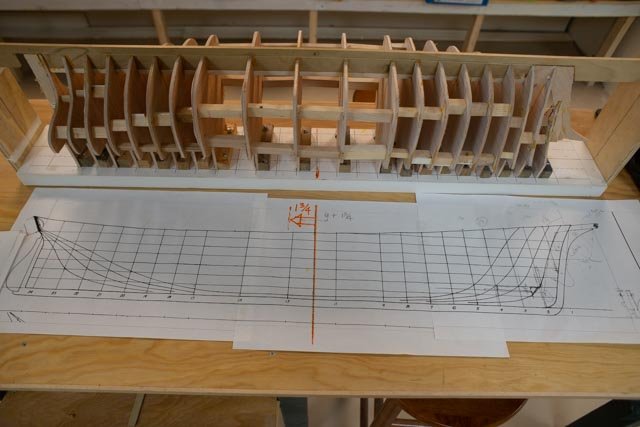
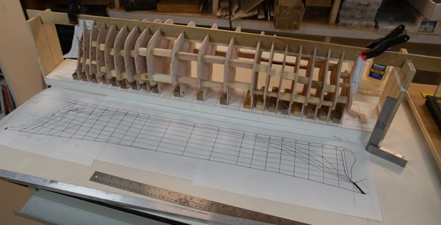
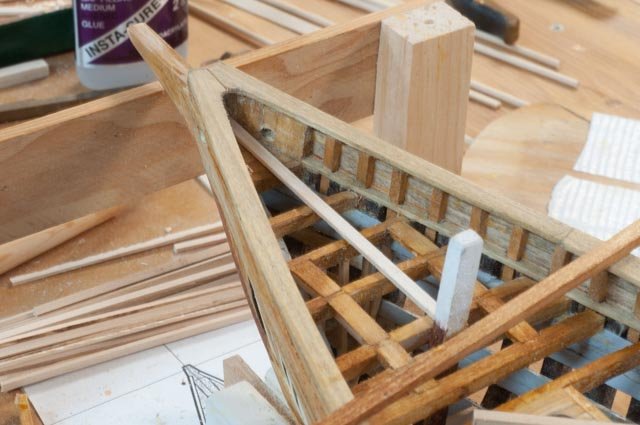
 here we are extending the building board. The pattern for dead wood and sternpost is laid in. a note is that after looking at the Ada Cliff photos, I decided that the transom was clearly closer to 8 feet than the 6-foot dimension on the older Bath drawings.
-
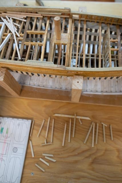
34
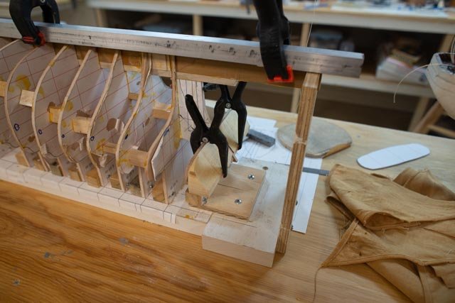
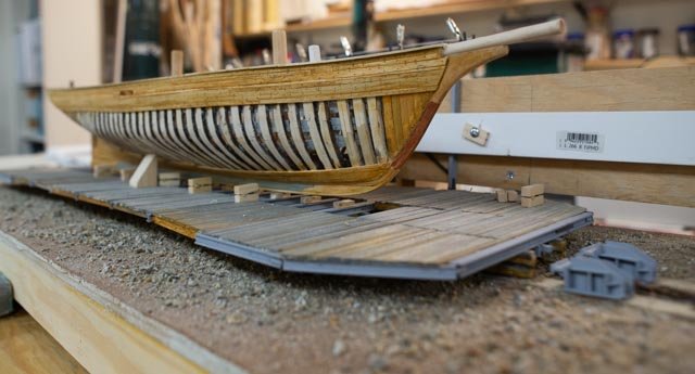
 here I used the aluminum box to hold all straight as I screwed the end post back into the building board and the small plywood square splice block.
Now I can go ahead and build up the stern. Since this is a bulkhead model, I can shape a block that is so much easier than the frame building I just did on Ernestina. I will save that joyous exercise for another build.
-
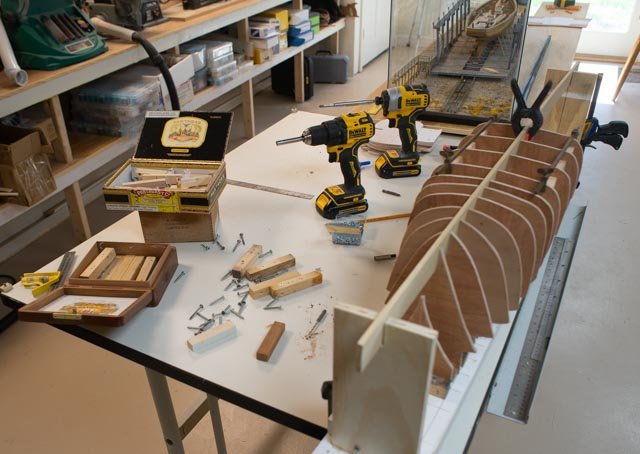
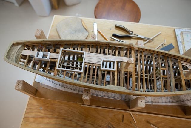
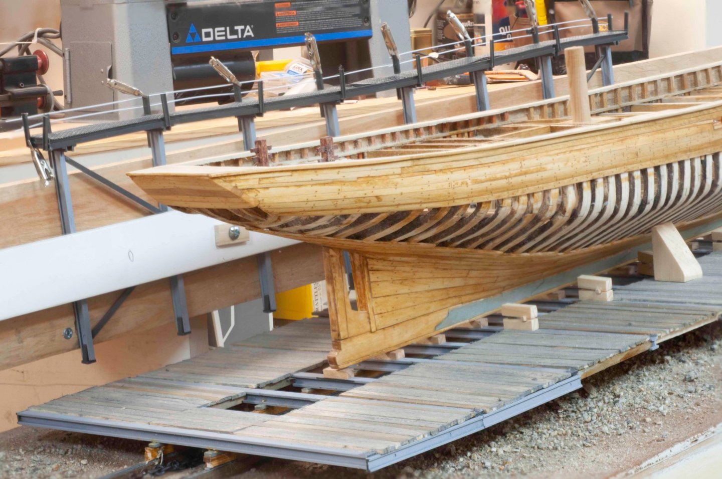
35
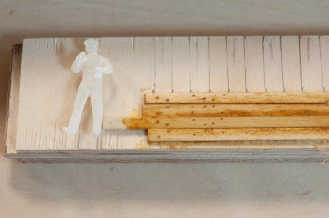
 in this view, I have taken some scrap pieces of Alaskan yellow cedar that I am using to rebuild my front porch. It is beautiful wood to work with and I plan to keep all the useful scraps for the model shop.
-
36
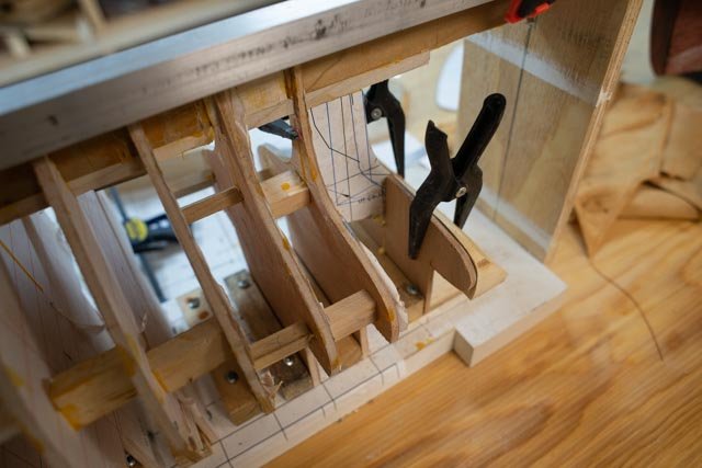 now I added in a transom station and dry fit the parts.
-
37
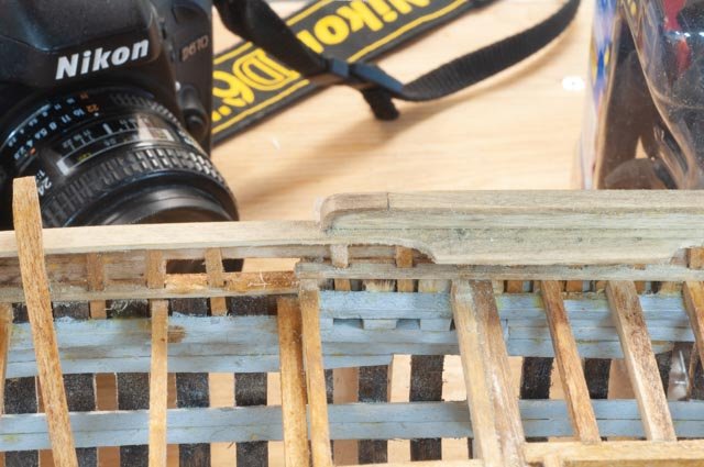
 here is the glue up to the transom station.
-
38
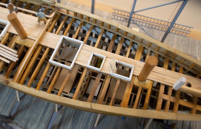
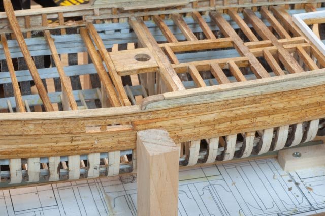
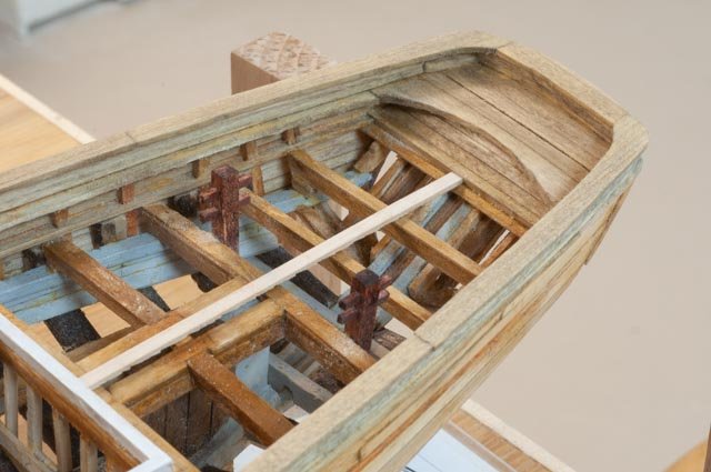
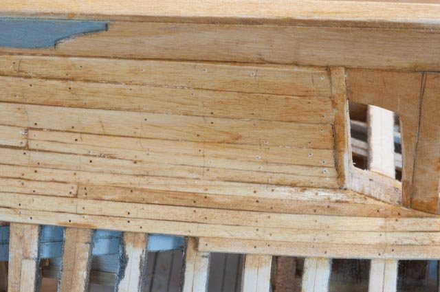
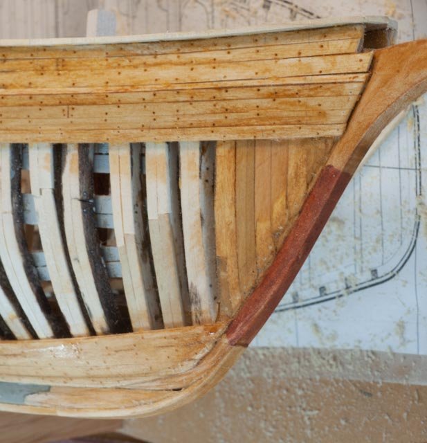
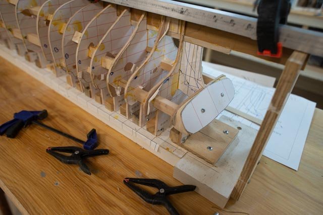 I have added a 1/16th piece of sacrificial plywood to act as the template for the future transom planning. I also need to fair things to fit the planking.
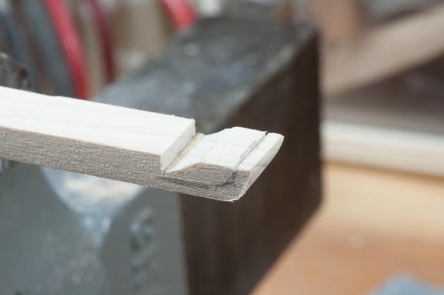
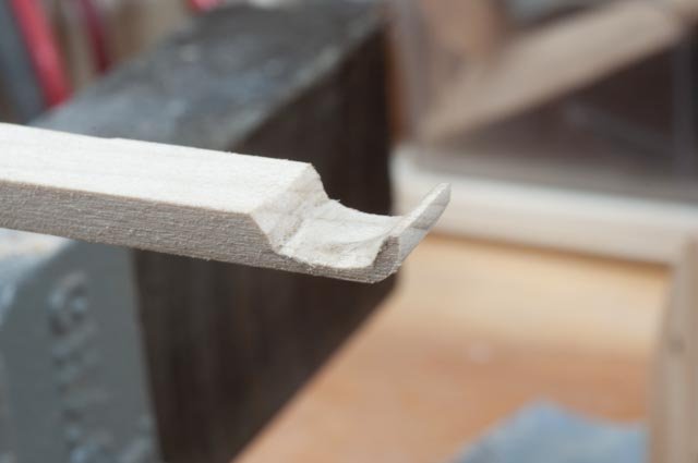
Now for the bow stem I simply added in some scrap balsa to help provide a better shape and give more surface to glue the curving planks. I have done this in pine on previous builds and thought this choice might be easier. We’ll see.
-
39
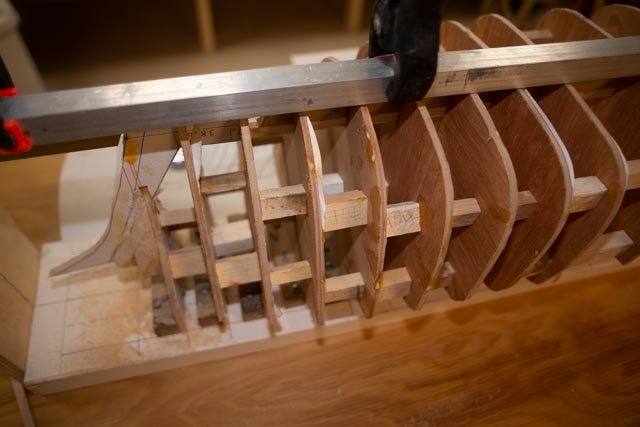 here are the blocks with rough fairing underway. Not too much sanding. I then need to carve the bow stem for the rabbit need to receive the planks. the "Bearding line" I think
All for now
- Cuda1949 and GrandpaPhil
-
 2
2
-
33
-
Michael
welcome aboard. The hull on deck when adjusted should be 37.25 which scales to 149 feet. I try on all my builds , as I focus on the ship building of the town here in Maine, to include what research I can. I always welcome suggestions and questions.
cheers
jon
-
Post 4
Yes, I am really going to stretch the model to achieve the new length.
I start off with a few images of Ada Cliff.
-
24
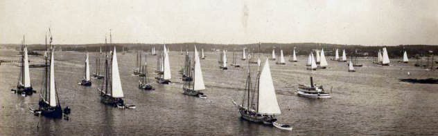
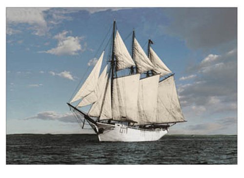 here from the internet is reportedly an image of her sailing toward us. It came from a website of a railway modeler who started off to build a model of her. The string seems to disappear, so I have no idea if a model is out there.
-
25
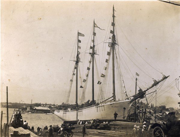
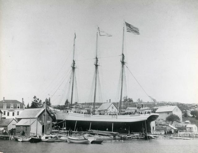 this famous image is all around the town here in Boothbay. I have a high resolution from the Boothbay Region Historical Society that will allow some blow up investigations. This photo shows the three masted Schooner Lillian Wooddruff being launched in East Boothbay in 1899. She is proudly perched in the yard of what most recently was the Lobster Dock Restaurant. As mentioned earlier, the hand me down nature of the design aspect of these schooners [ shipwright to ship wright] leads us to consider looking at these photos and merging the results. There are features that change but the main elements are consistent.
- Mr Cliff was mayor of Somerville MA and had a house full of co-investors. One of the reasons I like Ada Cliff so much is the story that she was used for the design of what became four each four masted schooners that followed her in the boom years. There is another view from the land side in an earlier posting.
-
26
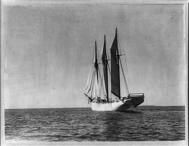 here is another image of her sailing away. I will be going back to the historical society and will find I am sure more relevant information.
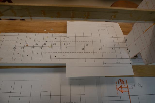
Now to grow 7 feet longer
I chose to use the same method the investors used when the deigned the first 4 masted schooner as Ada was finishing up. I will cut in the middle, add 7 feet [1.75 inches] and move the stern aft.
-
27
 shows the placement of the “cut”.
-
28
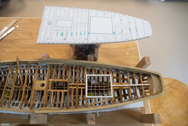
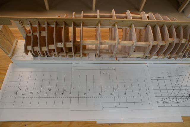 here we have the magic of Cad allowing a revised layout of the building board. I simply moved all the stations aft and added in a mid-bulkhead to fill the void.
-
29
 here I have removed all the stations. A little damage occurred, but I have no worries as they all made it.
-
30
 here the first half of the revised lay out is pasted in place.
-
31
 here we see the building board all ready. A little tight on the transom , more study needed there.
-
32
 here the stations are reset ready for spacers and re gluing.
Next up we need to finish the re bracing and regluing to get back to where we were before learning about the BOOK.
cheers
-
24
-
Post 3
It’s time to decide how long this schooner model is supposed to be.
I listed above the information that clearly showed this build had been planned to be 142.66 foot on deck Schooner. after reading that it might have been a 154 foot schooner, I used the sail plan from the museum to try to determine the right length. It had sail dimensions and I measured them all. The horizontal dimensions, when scaled to 142 feet, were off by 2.5-3.5% consistently. The vertical dimensions were off by 1 – 2%.
So, maybe the paper stretched. Who knows? My first thought had been to ignore that MIT catalogue and to go with the 142 as listed both by Maine Maritime Museum and Jim Steven's Downeast magazine article. If I took the maximum, I would add 3% or just over 4 feet. But 154 feet listed by MIT? I cannot just ignore it even though the late Jim Stevens of East Boothbay in my opinion had to been right.
The Book that stopped me!!
-
17
 oh the book here it is . it references the hart Museum and on their website they confirm the 154 feet on deck
The sail plan in the book was shrunk for better publishing fit. There is no dimension nor scale indicated. I put it in cad and scaled it to be like the sail plan from Maine Maritime. I tried multiple methods for comparing and not much comes out right. If am right, the plans from Maine Maritime and MIT do not seem to align. An example was to scale the two-sail plans for the same deck overall length. I then measured separations of the three masts and came up different. I think I am working too hard and need to come up with a solution before I restart a new hull for Priscilla Alden. The issue now is what to do with the hull I have roughed out as a start to this build?
Before deciding, I made a few more comparisons. First up was the transom
-
18
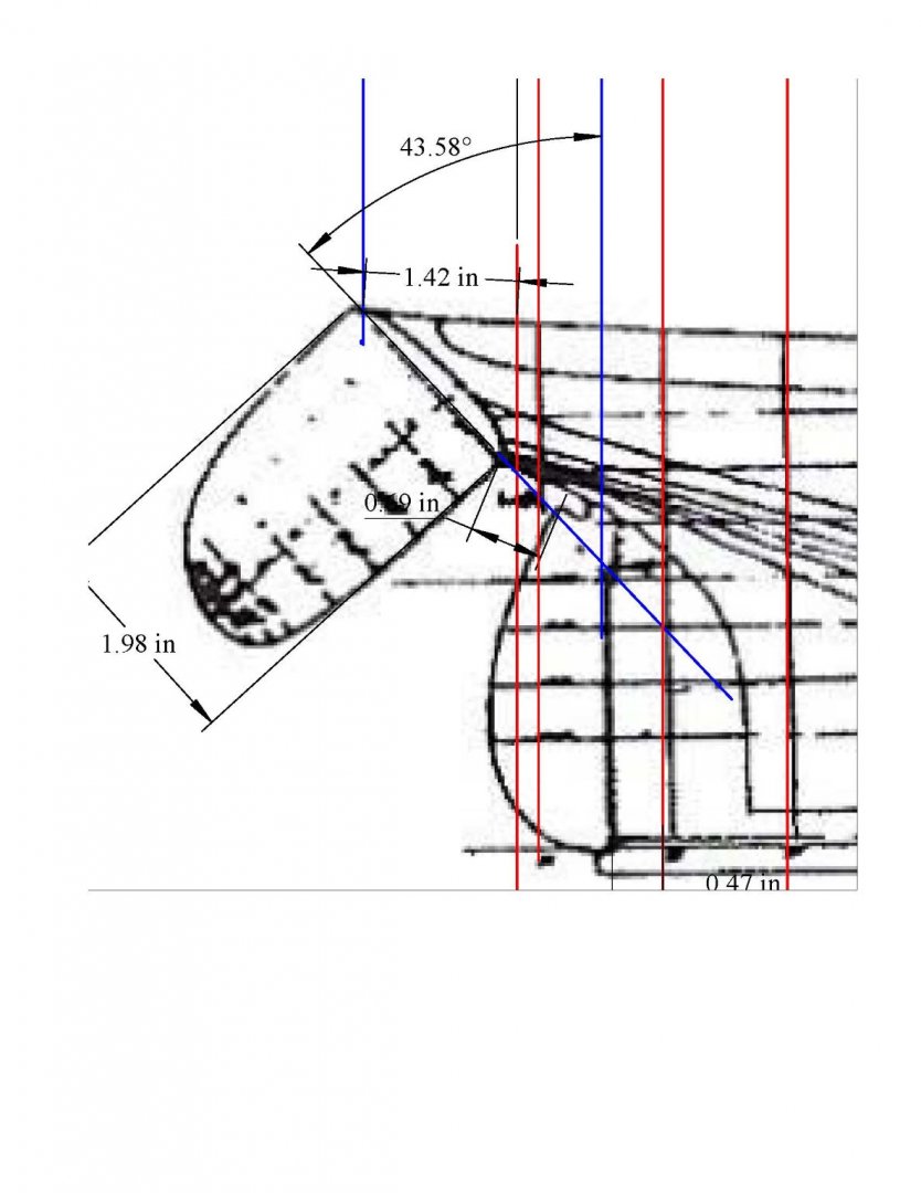
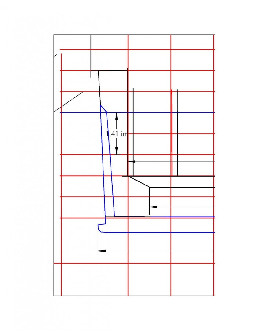
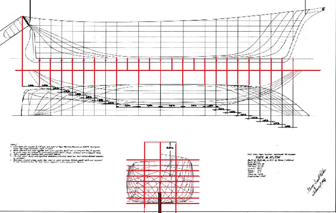
 here is the Kate Hilton section showing the transom. Roughly a 30-degree angle and 1.5 inches or six feet
-
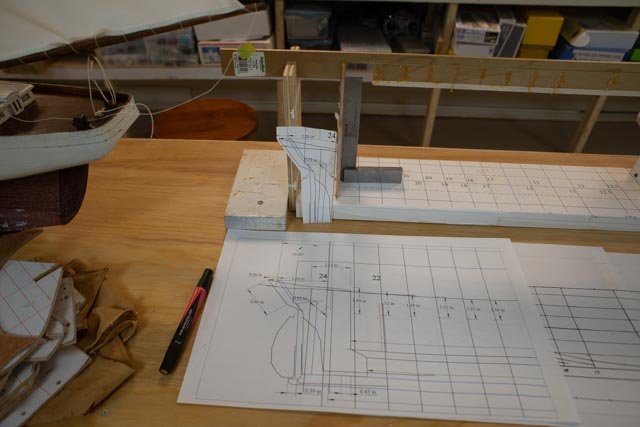
19
 here I take the station for the transom and stretch it to the measures 1.5 inches to make a pattern.
-
20
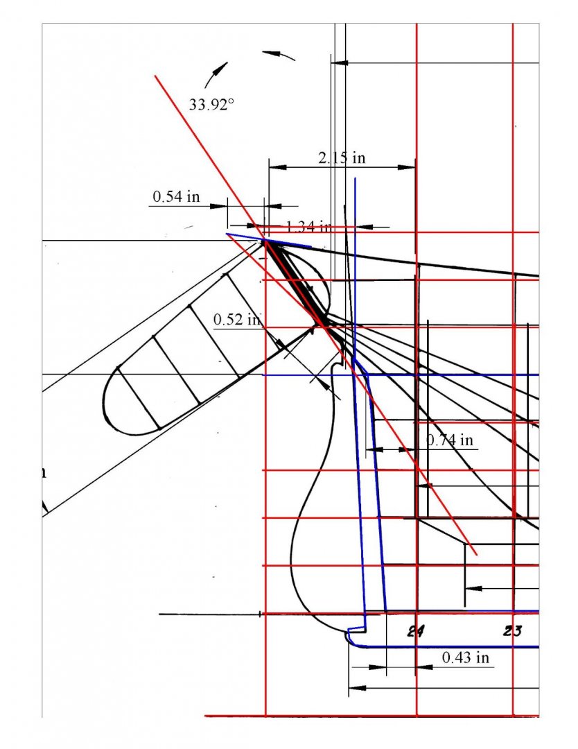
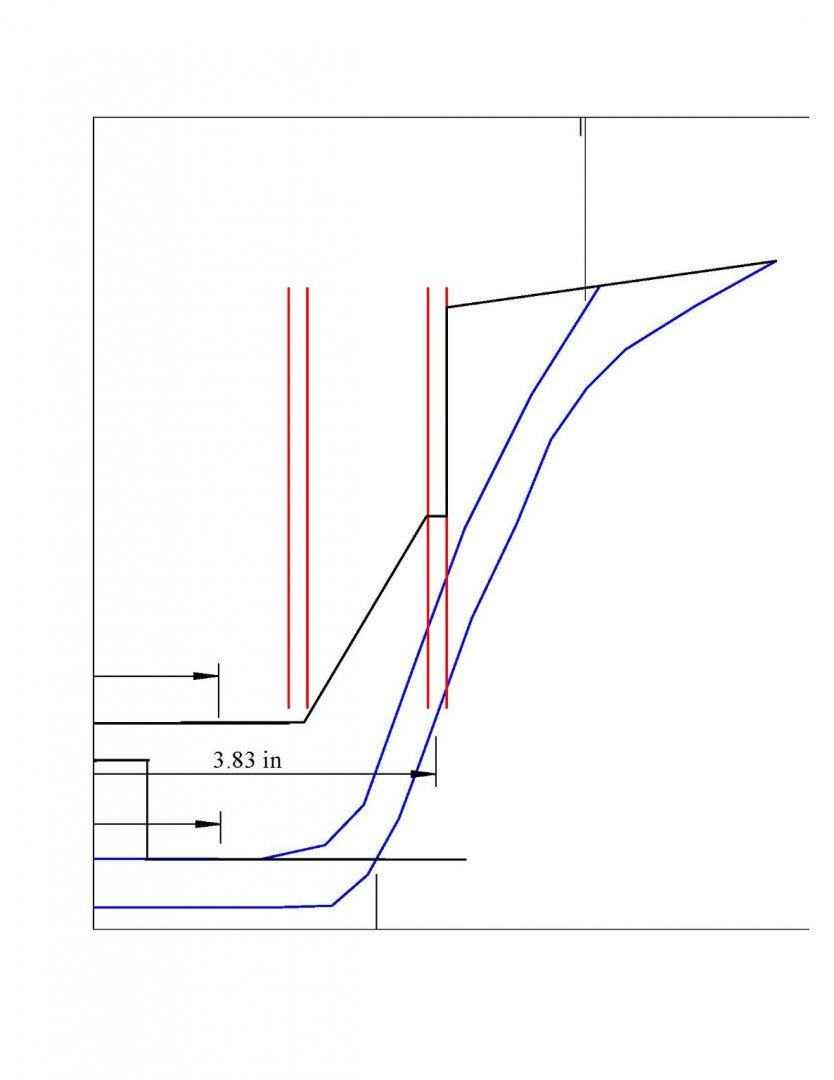
 here is the section on the scaled Priscilla plan from the book. The angle is roughly 45 and the and the slanted height nearly 2 inches or 8 feet,
-
21
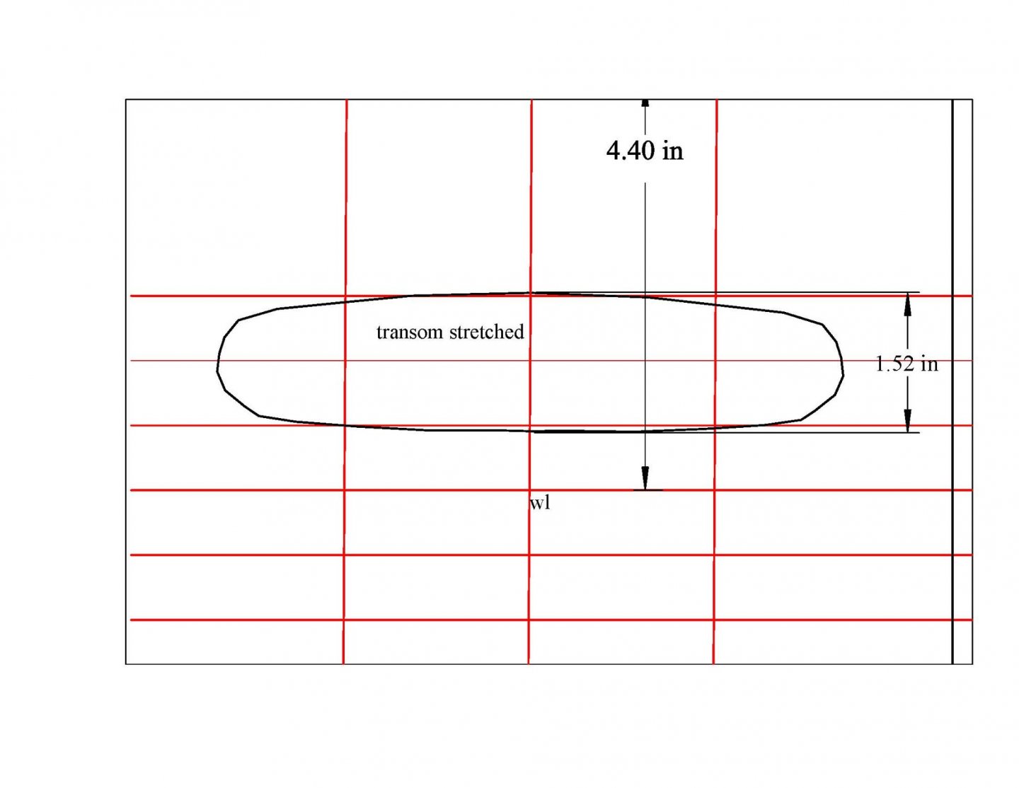
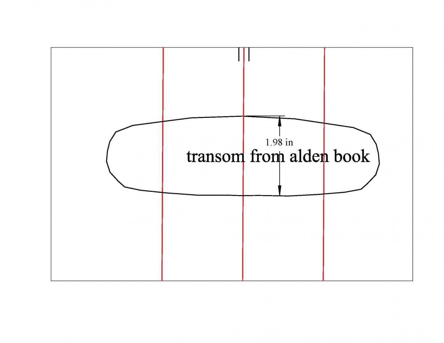 Here we see the difference in stretching the transom station to the new height.
-
22
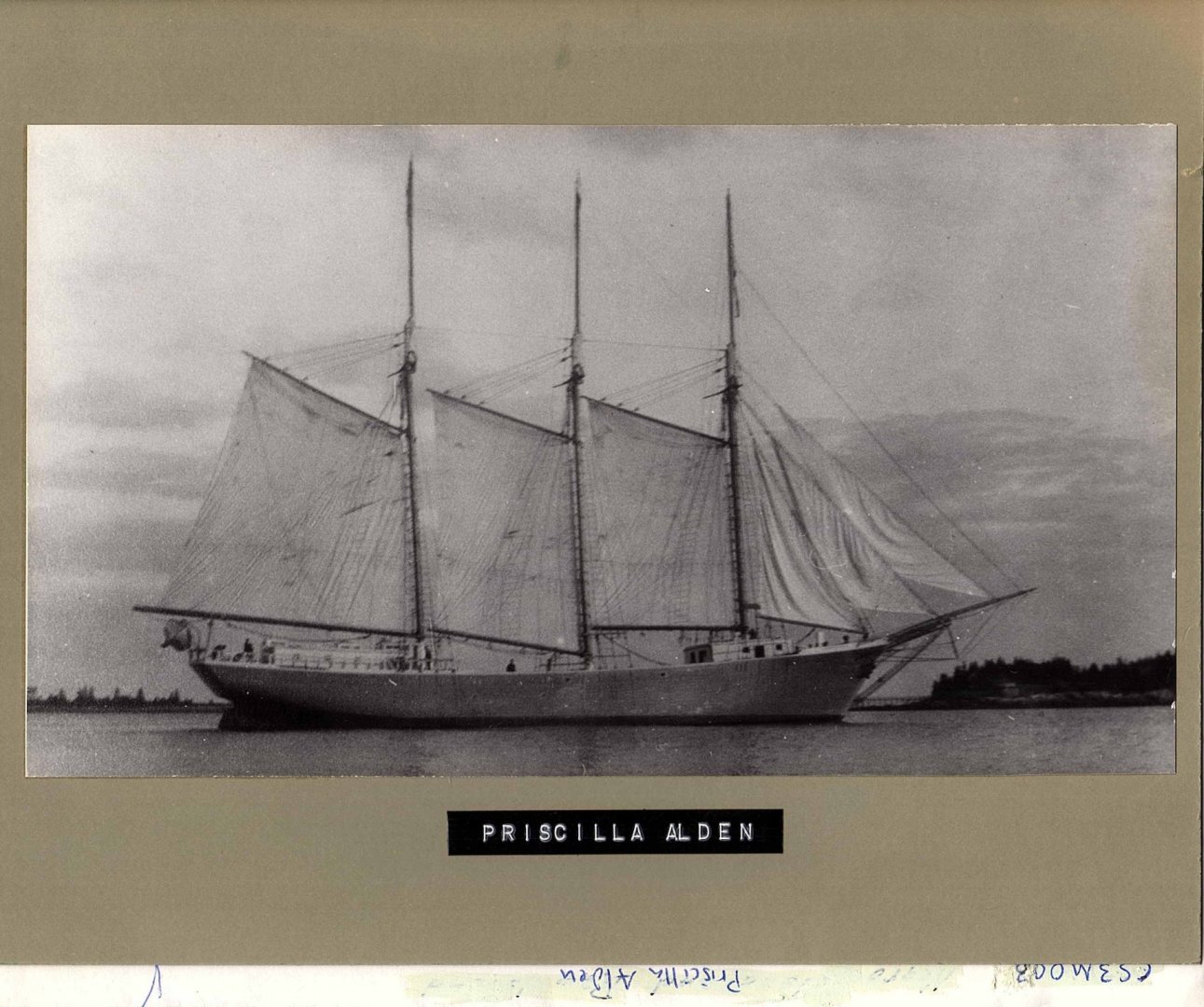 I got a great image of Priscilla from the Boothbay Region Historical society
My final comparison was to take the photo from the historical society and scale it to the 142 feet. I then traced the profile in green.
-
23
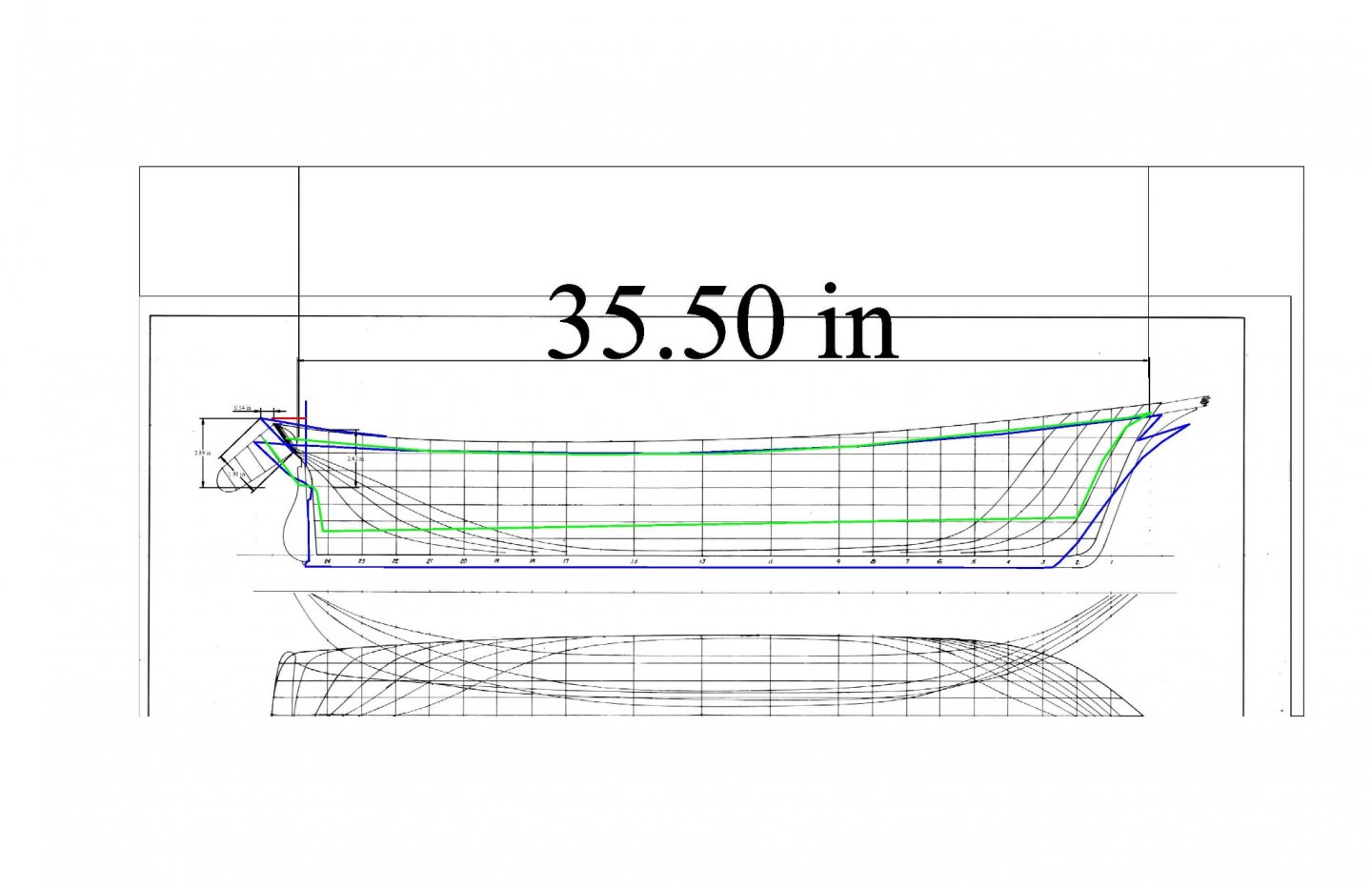 here is the result of the photo traced in green and the drawing traced in dark blue. [ the photo is cut off at the waterline] They are not the same schooner as the under image of the Kate Hilton hull.
So……..
Let’s look at the Ada Cliff. She was built at almost the same time over in the main Boothbay Harbor. She was recorded to be 149 feet. She was a production made schooner made for the coal trade. The owners built multiple schooners. In my research a few years back with the late Jim Hunt, we understood there are no surviving drawings or half models, around here anyway, that represent any of the big schooners built between 1917 and 1922. The owners were mostly from Boston, so if half models existed, they probably became artifacts of the various investors. I am planning to proceed by building the Ada Cliff based on the hull from Bath of the Kate Hilton and the few surviving photos of Ada before launching. I have already changed the name of the build, so I am determined to make it work.
Next up I need to adjust what I have to form the new length of 149 feet.
Cheers
- trippwj, GrandpaPhil and KeithAug
-
3
-
17
-
Post 2
Assemble the bulkheads and start the design for the bow and stern.
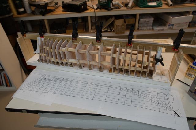
In this posting I share the process to assemble and get ready to build out the transom and bow. I can take advantage of reusing many leftover parts from earlier builds. I have several build boards that remain in the attic.
-
10
 in this view we see all the cigar boxes filled with bulkhead stops and screws from my earlier BHOD and Charles Notman builds. Having these already was nice. But the idea is to prepare all parts first and not as you go. The other step is to mark a 1/16” inner line on the edge of each bulkhead to allow for the planking. I then quickly and easily sand off this material, so hopefully the final shape of the planked hull is right, I find this process faster than trying to make the line in Cad. That is a choice.”
-
11
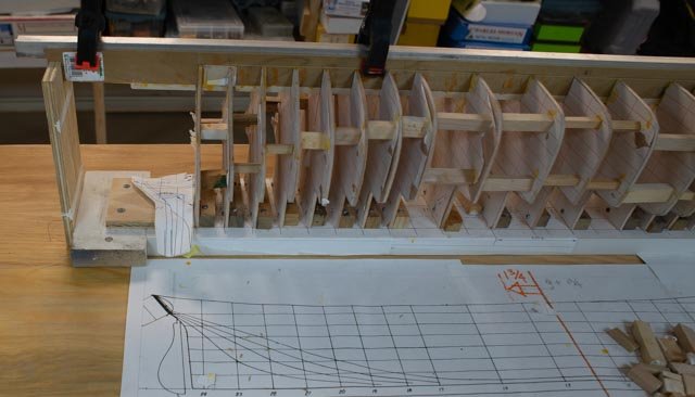
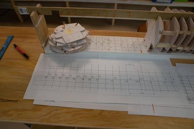
 in this view one can see the build board. When scaling the hull to 142 feet we find the bullheads are at 1.42 inches. That number like the .70 inches in the vertical grid is nuts to convert to fractions and lay out. I simply made a full-scale grid in cad and printed it out and pasted it to the building board. I then cut out a supply of spacers and using the square and a few clamps get it all square in the middle section.
-
12
 here is the cad template for the bow stem. I cut this out as the keel in ¼ “poplar.
-
13
 here is the template for the stern post.
-
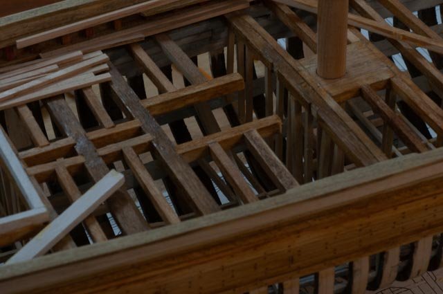
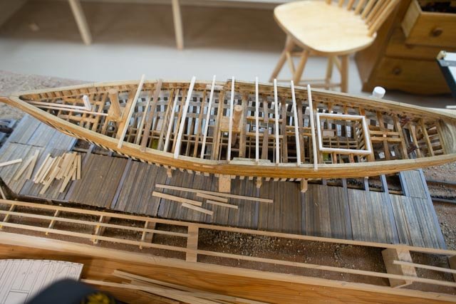
14
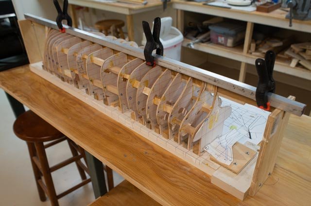
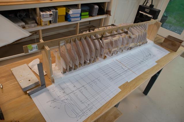
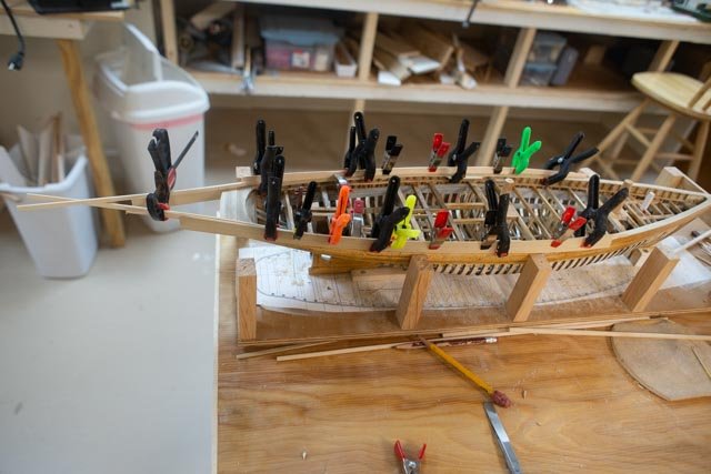
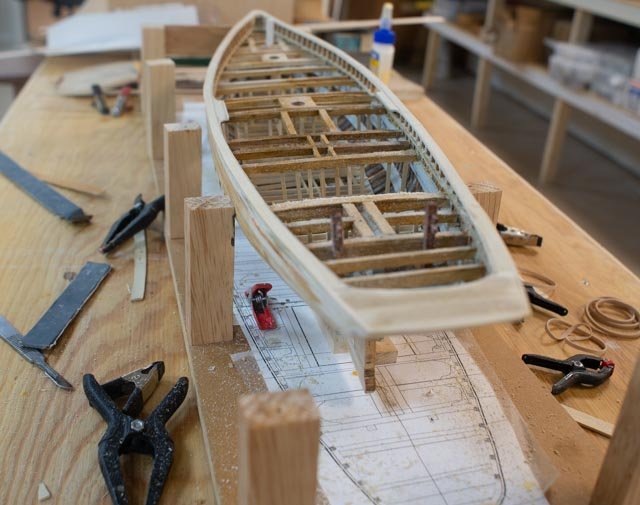
 here all the station bulkheads are in, braced and the two end posts are set into the keel. the strip for the keel extends both ways to be made fast in the end supports. I chose to cut up all the final remaining stops so after this build I will not have three cigar boxes to store again….smile
-
15
 here we are all glued up
-
16
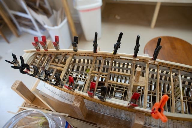
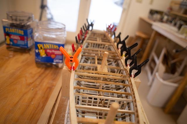
 in this view we see the square aluminum tube that extends the length of the keel with strong clamps to hold it as straight as one can during gluing.
all for now
- GrandpaPhil, bolin, Roger Pellett and 1 other
-
4
-
10
-
we made it to the museum store so that means finished.
- Roger Pellett, Richvee, Elia and 2 others
-
5
-
Revision to the beginning and name of build
I need to change the direction of the hull started in the first post and alter it to make the schooner the Ada Cliff.
There were two similar schooners built in Boothbay in 1917. One in Boothbay Harbor and one in East Boothbay. Ada Cliff has been recorded to be 149 feet and the Priscilla Alden is apparently recorded at two different lengths. The local records all show 142, but a Boston based reference suggests 154. The Ada Cliff was a more standard schooner as per her pictures, built to spec for coal. She became the design basis of several four masted schooners built in the boom years that followed. There is no remaining half model or drawings for Ada Cliff that the late Jim Hunt was able to find in his research, but several photos for reference. More on that later
I started off using a generic hull form described in the first post below. I then was able to find more references to the Priscilla Alden. Those references including surviving drawings showed a much sleeker hull. I have decided to use the framing I made in the first post to build the Ada Cliff and will hold back and start a total new hull later on for Priscilla. That will also give me the opportunity to study more about the disparity in the length.
The following first post will lead into Priscilla and the next post will bring us back to Ada
cheers
Post 1
The beginning
The beginning to a new project can often be a bit risky. For me at least I am typically a little tentative. Will this be small or large scale, plank on frames or bulkhead model or a diorama? In this case, I want to build a three masted Boothbay built coasting Schooner. What is interesting is that I rushed into it and started making sawdust before fully sorting out my research. First of all, I wanted to explore this design because after studying the bigger schooners, and learning firsthand the poor sailing aspects of the “too long” form, I wanted to get to what seems to have been the most reasonable solution. That is 3 may have been better than 4.
Three masted Schooners a quick summary
• The first 3-masted schooners evolved in the Chesapeake region around 1790
• The three masts were adjusted to be the same height around 1850
• 1840-1865 full rigged ships looking for speed evolved into clipperships
• As steamships took over for long hauls, coasting schooners, with less labor costs, took on coastal routes
• 1865-1880 coastal trade blossomed as the US government required US flag vessels for inter-city trade
• The coastline favored long narrow fore and aft rigs (like clipper) with small crews
• Coastal schooner construction grew quickly, and the 3-masted fleet competed with steam ships along the coast
These beauties became prolific in the decades after the civil War. Then, as human nature and business models dictated, they grew until the sails became too big. Then the plans changed, and a fourth mast was added to improve the sail handling and keep the sizes growing. As we know that cycle repeated itself across Maine until we ended up with nearly ten 6-masted schooners and one steel hulled 7-masted schooner by around 1910. Then, except for the World War I short termed boom, steam took over .
01a
 Looking at the local Boothbay market, we learned that through this period schooners built here were prolific in the two masted fishing arenas. From 1873 to 1903, nine bigger schooners built. In East Boothbay, four masted Schooners were launched from the Adam’s yard in 1890 and 1903. Jim Stevens, one of the area gurus, put together a story listing 21 3 and 4 masted schooners built on the peninsula. There was a complete void until in 1917, when it all came back in a roar.
'
01b
 In the main harbor in the year 1917 the Ada Cliff was being built at the I R Reed yard. That year the Mayor of Sommerville, Mr Cliff himself, and lots of investors came, bought that yard, and built four 4-masted schooners over the next few years. They took the partially built Schooner Ida Cliff lines and simply stretched them 40 feet in the middle and then added a fourth mast. Anyway, someday I hope to build a diorama of all that stuff. It is not for this build. What is of interest is that in 1917 the IDA Cliff was a 149 foot long three masted schooner and that was pretty much as big as they got. Just beyond the big roof in the phot, on the other side of the harbor, the Atlantic Company was set up and they built 6 more 4-masted schooners before then end of the era in about 1921. More on that when I get back my next 4-masted build.
I am now focused on East Boothbay. I have selected a 1918 Schooner, the Priscilla Alden. I chose after searching all the names on the list I had and found at Maine Maritime Museum an authentic copy of her sail plan to use as a basis. Their list advised the schooner to be.... Length 142.8’. Traced from Charles Sayle original by George S. Parker, 1982.
In that late year she was built at the end of the era of three masted schooners. Those built later would have been an exception. Fishing schooners continued to be launched into the 1930’s but three and four masted pretty much stopped in the early 1920’s in the post war era of steam. The Priscilla Alden comes up in a few publications. The late Jim Stevens of Boothbay wrote an informative article, Boothbay Schooners in Downeast Magazine published in Sept 1968. At the end he listed Priscilla to be 142 feet. I suspect with his working often with the Maine Maritime Museum that they shared sources and that is why they agreed. It is the length I plan to build.
A challenge was to find a hull plan big enough to use in cad to match up with the sail plan. Here some artistic license in needed. I found in the Maine Maritime Archive the hull lines for several three masted schooners. One, the Kate Hilton was built in Bath and had remarkably similar characteristics. She was 140 feet, so I chose her and down loaded the drawing.
Maybe a False Start I thought that this data was enough information to go go go
A month in and the local Historical Society has reopened for us hobbyist to come in and do research. I signed up right away and this week went down to spend time going through several files. Most important however was photocopied pages out of a book. The book John Alden and His Yacht Designs written by Robert Carrick and Richard Henderson. On pages 86-88 there is a set of plans that include, sail plan, lines, deck arrangement, cross section bow to stern as well as an amid ship cross section. There is enough information here to build anything. Unfortunately to scan the line drawings, approximately one inch square, and to blow them up in cad got a bit fuzzy mess. I found the book on Amazon and await a better original for scanning. The problem I discovered however is they declare the schooner to have been much bigger. WHAT??? We’ll see
So let’s start off with the steps I took to rough out and make bulkheads for a good start.
Design
-
02a
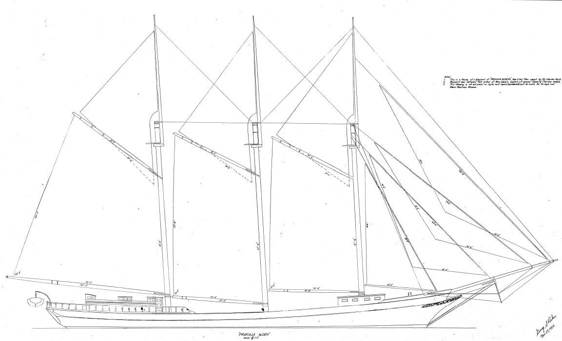 here is the sail plan published by the Maine Maritime Museum. There are dimensions on all the sails. There is a little variance[ between 1-2%] between vertical and horizontal found while measuring the image with CAD.
-
02b
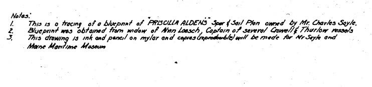 here is the source as printed on the drawing. Key word for me is blueprint.
-
03
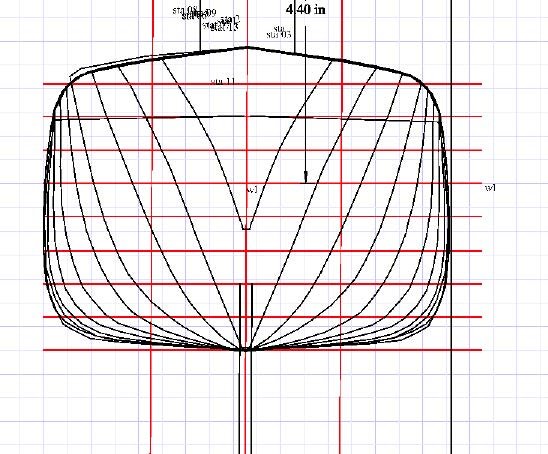
 here is the selected hull plan for Maine built schooner in the same size. I made offsets from both the sail plan and the bull plan and in scale the difference was the sail plan forward shear line rises about 1/8th inch higher than the hull plan. That is close enough for me. Maybe when I get there, I add that 1/8 inch in…we’ll see
-
04
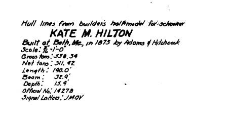 here is the source of the kate hilton hull lines
-
05
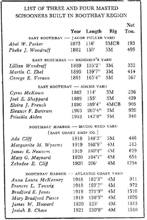 here is the Jim Stevens chart from the 1968 article in Down East magazine. It clearly shows Priscilla to be 142 feet. Of more interest is the low tonnage. IDA Cliff at 149 feet built the same year in the main Harbor was 25% heavier [ volume that is] as she was made for maximum coal transport. Priscilla was lighter and most likely a faster sailor. More on this argument later
-
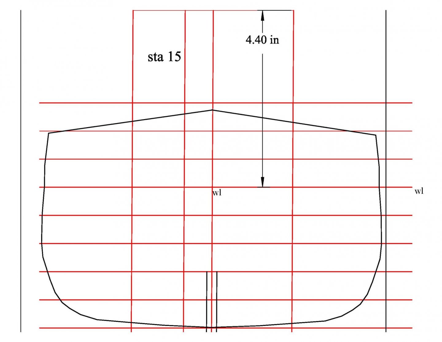
06
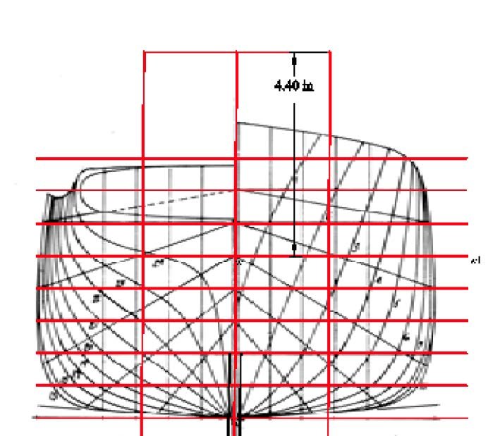 here I have laid out the cross sections the rectangle that will be used to support the bulkheads to the building board, making the waterline 4.4 inches above the board. That will come in handy at the time of marking the water line.
-
07
 here all the layers are turned on for the forward sections.
-
08
 here is what the pattern looks like for one of the bulkheads. The keel/keelson slot is important to the assembly. I did not sit for a while and add the extra cut line for the planking thickness. It takes me much longer that striking a line by eye .
-
09
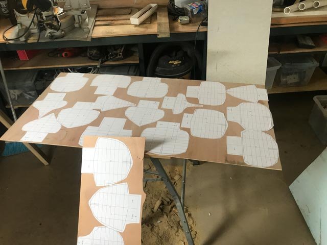 the patterns are all glued to a simple Luan plywood from Lowe’s. They are ready for cutting out . I will adjust later for the thickness of the planks.
All for now
-
02a
-
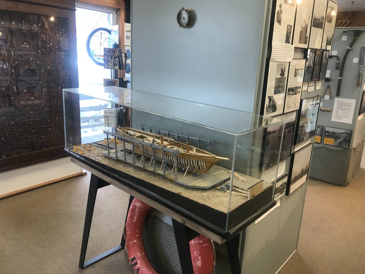
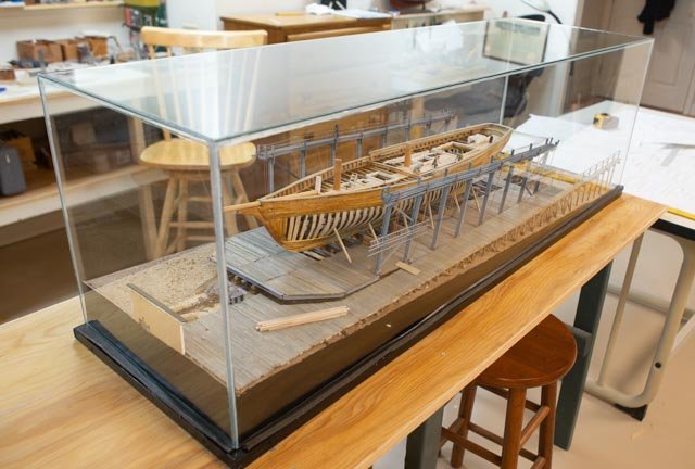
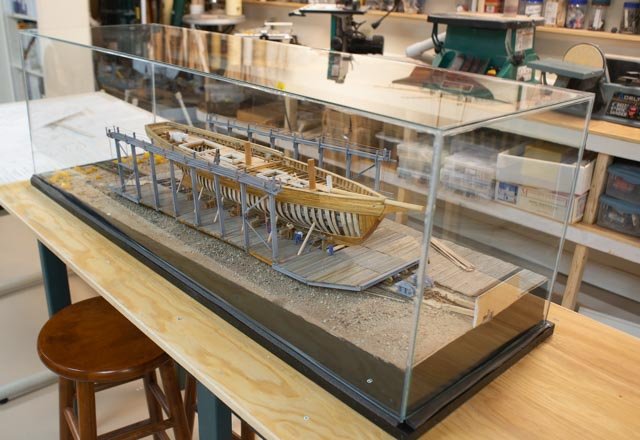
Building a case for model can be a fun challenge. I tried for my last diorama but it did not succeed. This time I made a sketch and went back to the local glazer who does a nice job
345
 i made a sketch and measured it twice
346 to 349 i am happy with it. i hope it makes it to the display next month
cheers
- GrandpaPhil, Roger Pellett, Elia and 2 others
-
5
-
Post 32
the end..... sort of
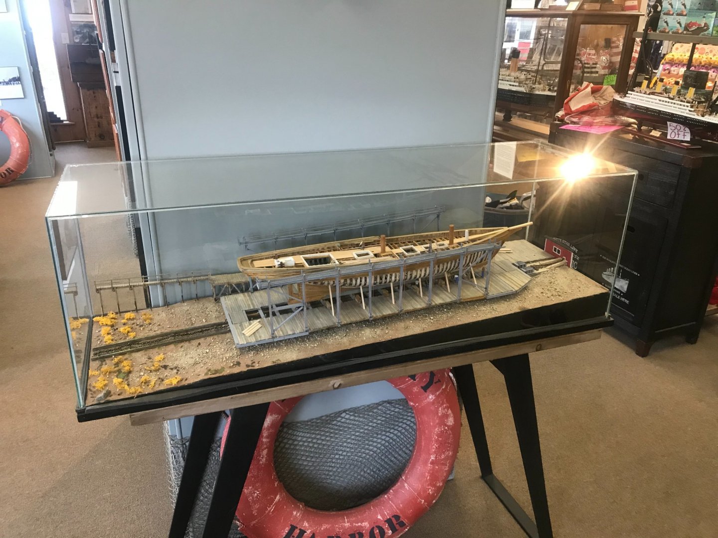
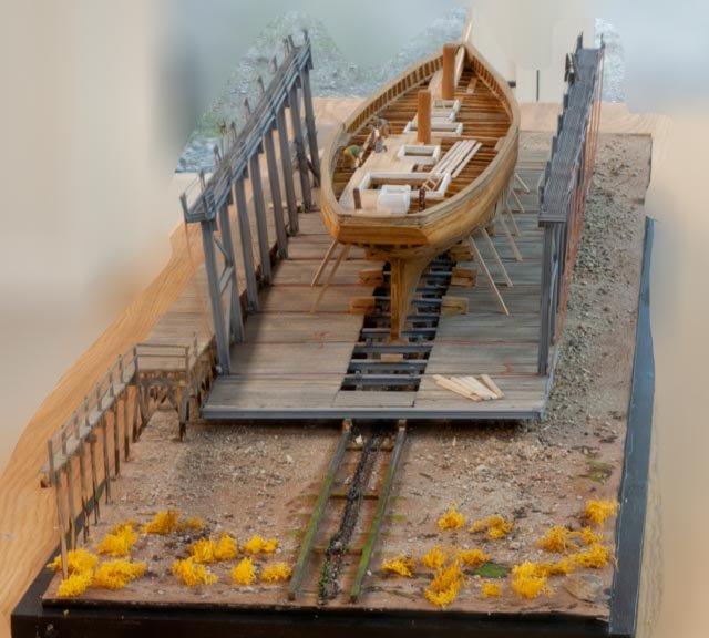
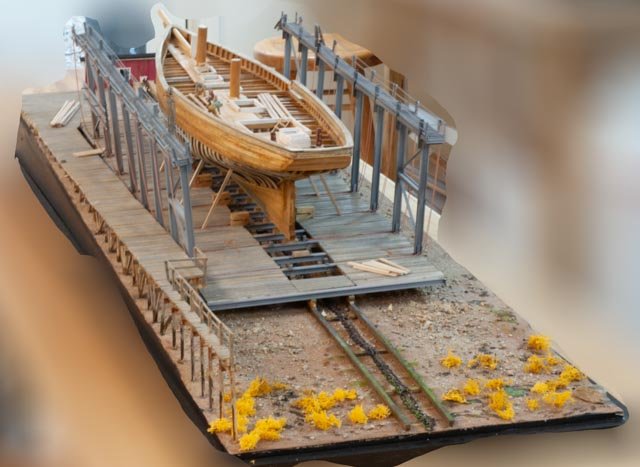
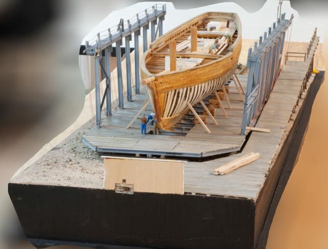
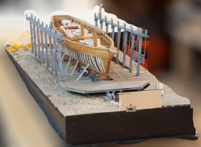
It seems when we get to the end of a project it is more subjective than definitive. There is always more detail we could add. Anyway, I think we are there. Below I have a bunch of photos to capture the completed diorama before it disappears under a case.
First up are four view from the 4 quarters
-
328
-
329
-
330
-
331
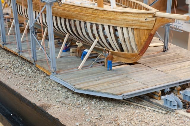
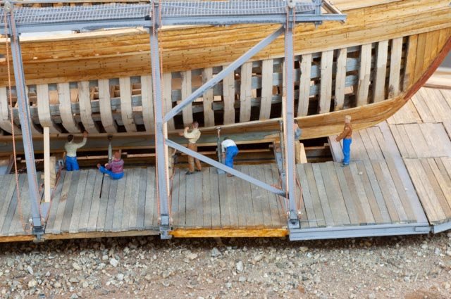
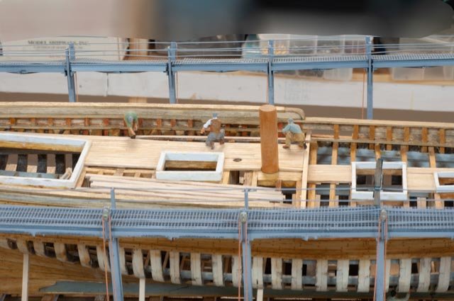
Now three pictures of the crew
-
332
-
333
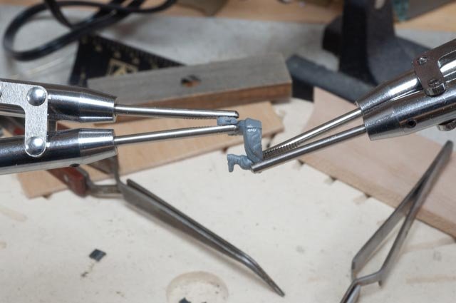
 I added a few jacks to hold the new plank
-
334
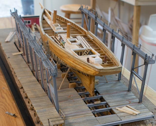
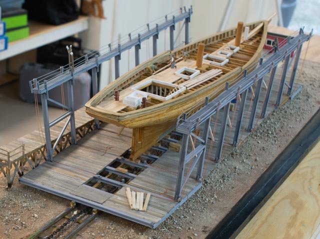
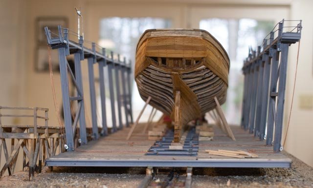
Now six views of the hull
-
335
-
336
-
337
-
338
-
339
-
340
Three looking down at the decks
-
341
-
342
-
343
And one for the chain windless shack. Oops I need to add a building 3 sign.
-
344
In the next month I will get a glass case…I think and then we’ll see where she goes
Thus it is the next posting that will say finished
Cheers
Jon
-
328
-
Feb 2021 Update on the sails
As I described last time I get a few hours each Sunday in between other activities that I choose to work on this project.
-
1107
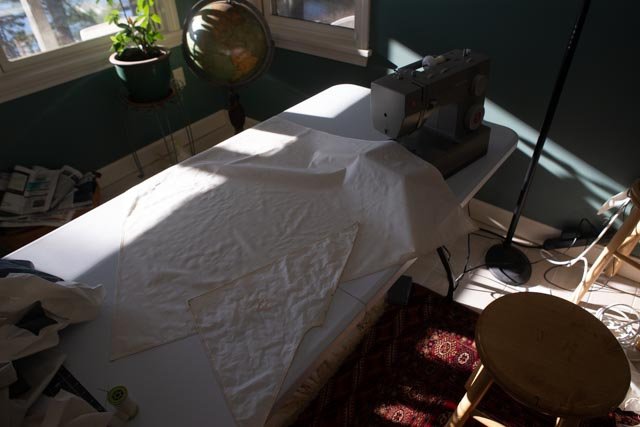 at the beginning of January we see the replacement main sail in the sewing machine as my daughter made a great contribution needed to get me going again.
-
1108
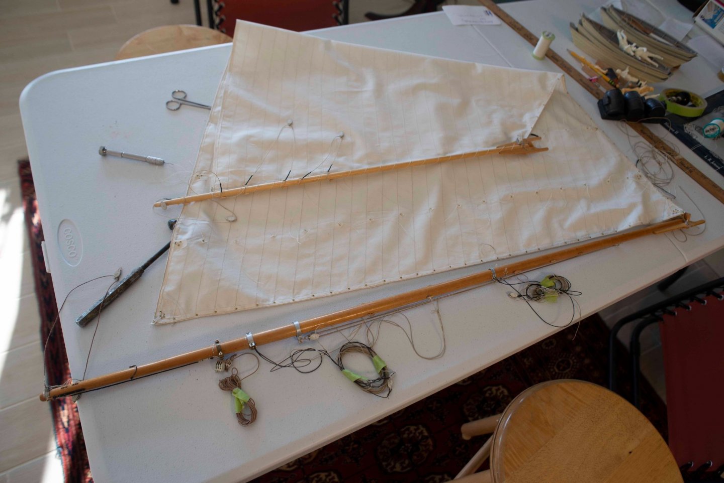 here we are at the end of February with the reef points in, all the grommets in, and the head lashed to the gaff. In March we should get lashing to the boom, sewing to the hoops and prepping to be ready for rerigging.
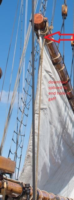
….As I mentioned, I will also add the detail of the down hauls to the gaffs in this update.
-
1109
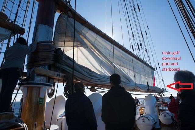 here as the Bluenose II mainsail was raised, we see the main gaff down haul is on both port and starboard
-
1110
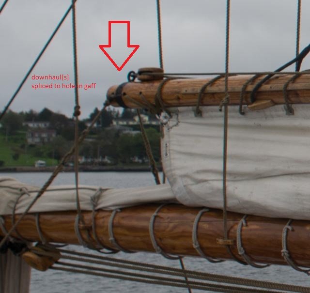 this detail shows a few things. The down hauls act like quarter tackles holding the gaff steady when lowered. The lines are spliced using holes through the gaff. The other two of three holes take the lanyard/ lashing from the head of the sails securing it to the gaff. Most interesting to me was the location of the topsail sheet block. In traditional designs the block is attached to a leather holster type devise that allows it to rotate to the up-wind side while racing. I assume for fishing it was permanently on the starboard side.
Sailing out to the banks in New England our prevailing SW winds, the sheet would have been tight headed outbound; thus, the starboard side. Returning home would have been a reach or more downwind, so no there was no need to move the bloc around. Too much thinking on my part but that is my previous logic for placing those blocks to starboard.
By riding on the top of the gaff there is less issues as to the tacking. Only the tack lines are doubled to allow pulling the tack up and over the gaff. Again, I am sure this is a racing feature but not sure if for fishing they would have worried. The top sails were most likely flown only on the outboard and return legs.
-
1111
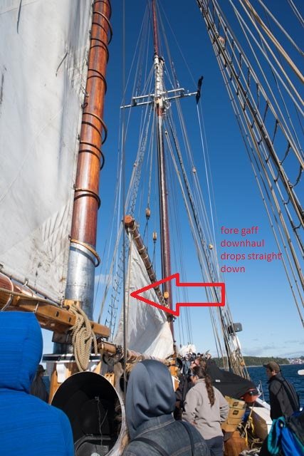 shows the fore gaff down haul. The photos don’t catch all, but the line was made off to the main fife rail on the starboard side
-
1112
 this detail shows the line is also spliced to the gaff through a hole. The sail lashing was was secured by hitch and there were not three holes
-
1113
 so back to my work. You can see I had a traditional application for the main topsail sheet block on the starboard side using hardware. I will be changing this to update the ringing to what I saw in Canada
All for now
-
1107
-
thank you Keith. it is something I needed to do. I have a few others that i need to drop back on too. we'll see how it goes
cheers
-
Post 31
Stands chain and work crew
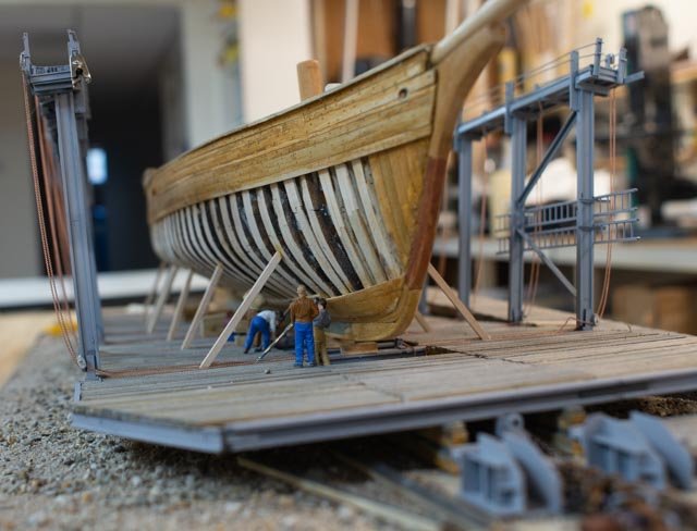
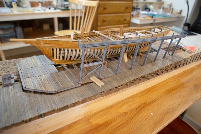
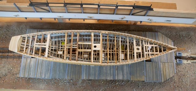
I believe that telling the story of the railway and how it works is a key part of this build. It has been here and active for 150 years and quite a marvel. In normal years there are many different large yachts, tugs, science boats and schooners that come up for underwater work. For the past 5 plus years the yard has been fully dedicated to this re build of Ernestina and that is what we are trying to show.
Stands
For the full story one needs to go back to photos 144 and 145 to see the stands engaged against the hull when Ernestina was hauled. Once the planking and framing was removed and the hull rebuilt, the stands needed to be rebuilt to facilitate launching.
-
316
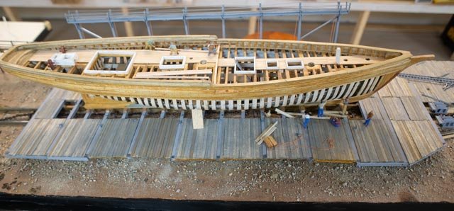
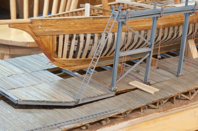
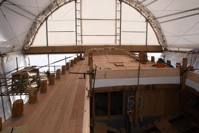
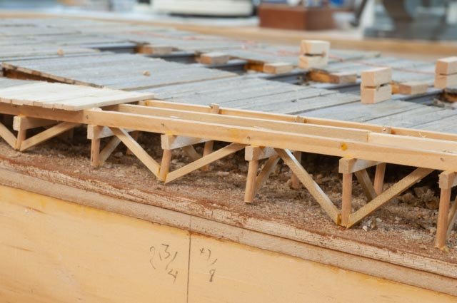
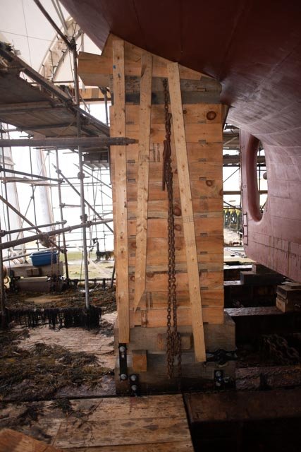
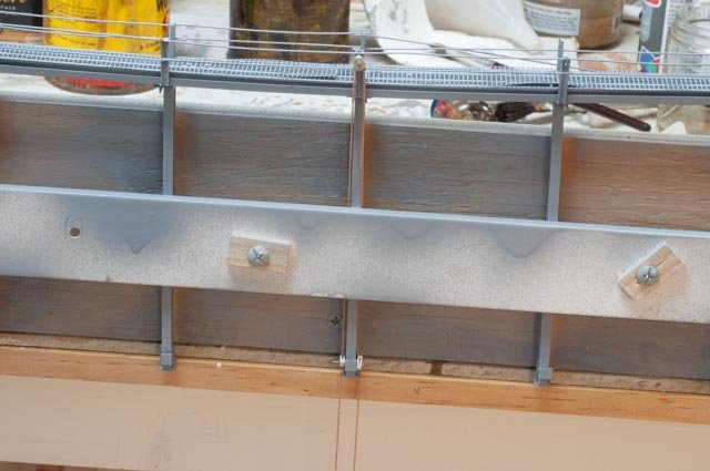
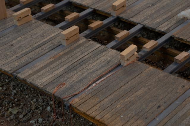
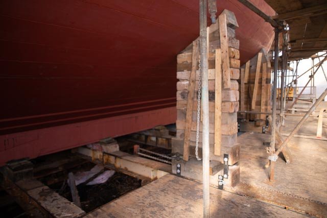 here is a new built-up stand that supports the hull after the planking is done. At this point all the painting is done and the stands are in position ready for launch. There are five of the eight on each side engaged. The chains on the deck allow the stand to be pulled away from the hull after the schooner is in the water and started to float free.
-
317
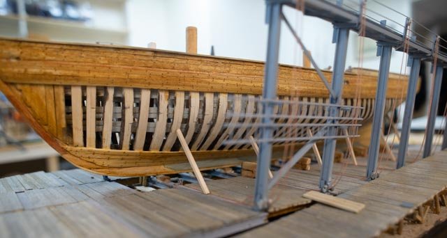
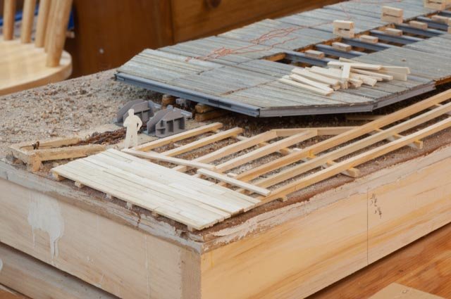
 here we see at the aft end the base is in place. there is a 6x6 post beyond. This view of the base is how I plan to show the five active units because before completing planking poles were used and continuously relocated to allow planking. Those bases at the extreme ends were laid aside to allow better access.
Chains and tide
-
318
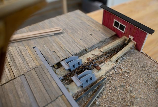
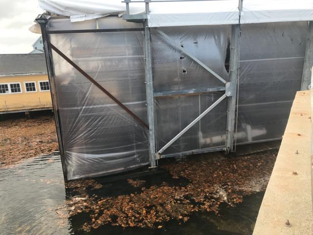
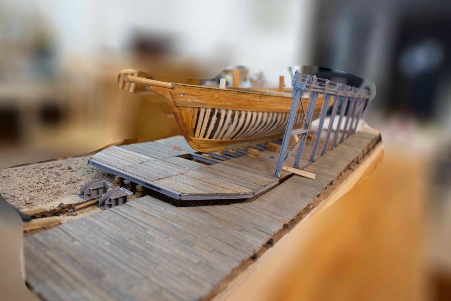
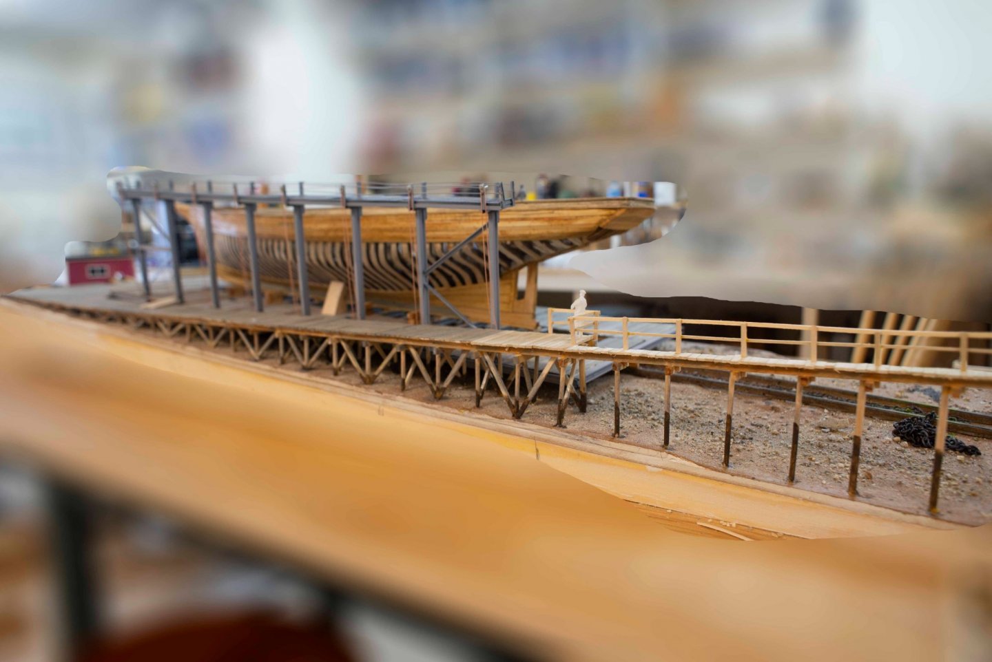
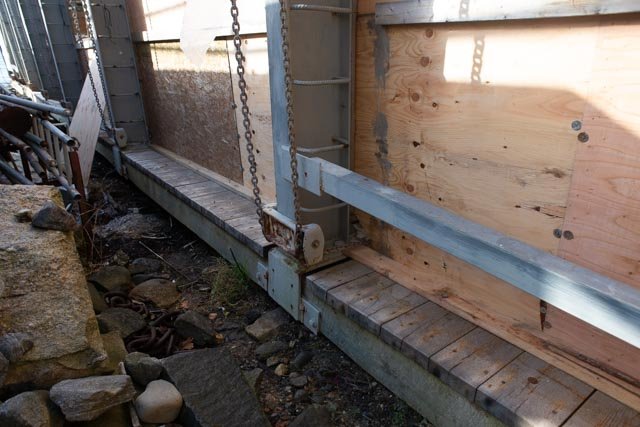
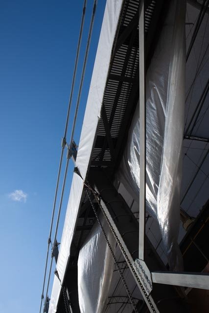
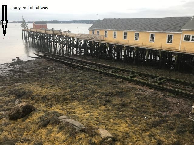 In this view we are need a low tide. We can see the red buoys marking the end of the railway. The dock in this view is shown on the edge of the diorama to help orient the viewer. See the tide marking on the piling. We have 9–10-foot tides in the harbor.
-
319
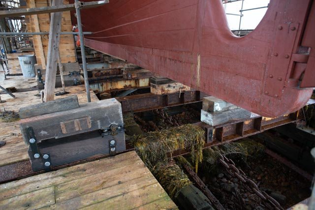
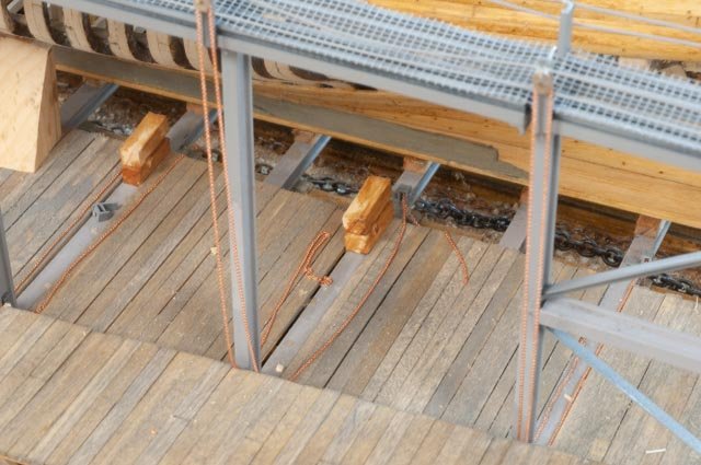
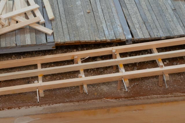
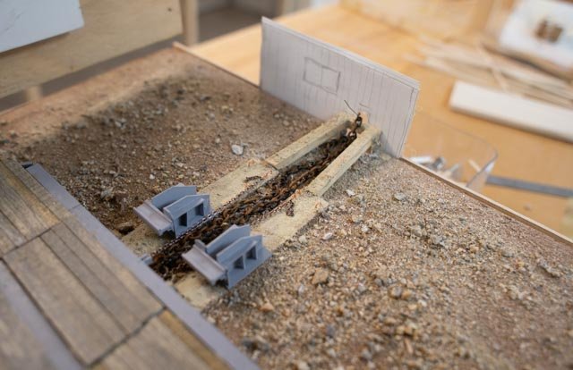
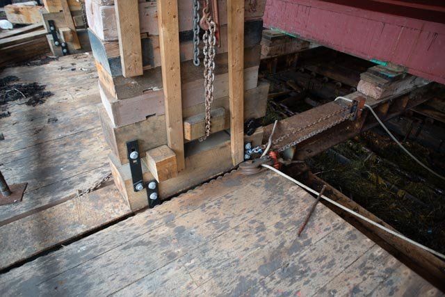
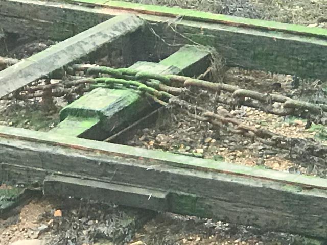 here is a closeup of the chains laying out into the harbor. The large chain does not go all the way out. The smaller chain is hooked to it and rounds a sheave underwater.
-
320
 here the smaller chain hooks into the railway car about 2/3 the way forward. Is is used to pull the car down the slope into the water at launch. The bigger chain continues up and into the windlass for hauling either out or in and connects to the front to the car. Note the large amount of seaweed even this far up the railway.
-
321
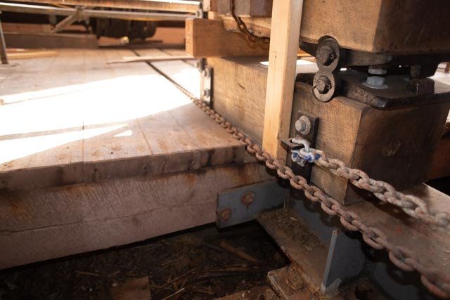
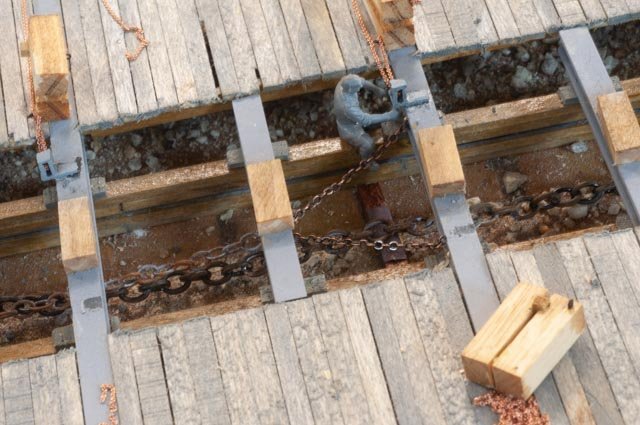 here I have connected the smaller chain to the car. One of the work crew decided to check it out.
-
322
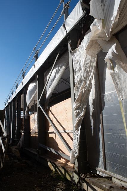
 this view is a typical near high tide. The water came in and up to the deck of the railway most tides. I debated what to do and deferred to the easier low tide approach.
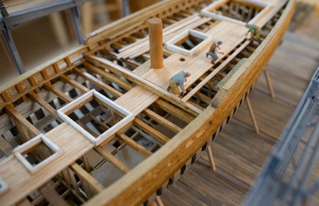
The work crew arrives
-
323
 I went to eBay and found a model kit of 9 German army tank workman and thought to give it a try. I filed off their soft hats and roughed up some of their uniforms before painting.
-
324
 I think I want to show a bunch of them working on the hull planking. It was funny as the loose schooner kept sliding and knocking the guys down. I need to fix that oops.
-
325
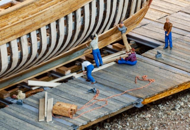
 here is the planking crew
-
326
 here is the decking crew
-
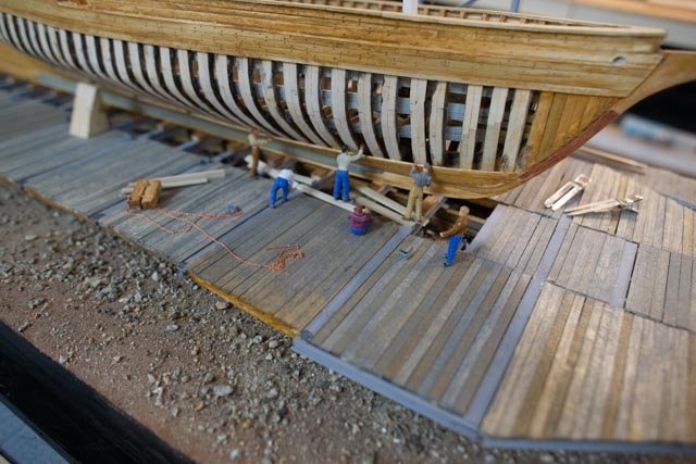
327
 Here we see both, and the new black pained trim around the diorama.
Next up
I realize I need to set the schooner on the railway permanently. That means any work needing to apply force needs to be done. Therefore, by next week. work on the schooner per say will be wrapped up and the remainder will focus on details and the overall story of rebuilding. Finally, I need to complete the diorama parts, painting and seaweed etc.
-
316
-
Post 30
Setting the first steel platform
Saturday was exciting, as I took the plunge and set the first dockside platform.
-
306
 here I have laid down the assembled platform and attached all eight of the small chains assemblies to operate the stands.
-
307
 one subtlety in this photo for my record is that the platform I am raising is actually for the other side. Can you believe it!!! I figured it out only minutes after gluing it in place…..I will explain below
-
308
 here we are with the ABS welding hopefully going to hold
-
309
 I had to set Ernestina on the railway to see the impact
Here are three fun views of what is coming along
-
310
 the bow over the dock
-
311
 the stern over the dock
-
312
 the stern over water
Now to the next steps of work
-
313
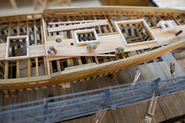
 here on deck I have started making 7 figures from an army tank model kit. I shaved off their hats. We’ll see what type scenes to make.
-
314
 here the access planks are being placed, the ladder was placed only for measurement. The two ladders will be hanged on the dockside of the steel platform columns. Here also for the last time the horizontal steel member in the first bay. It was supposed to be on the water end bay. Oops I mistakenly switched them. so now I must take out this member and place one like it at the far end.
-
315
 here is an early view of the stand set up with the chains. , the real ones are dirty galvanized. I plan to leave these now as visible copper just make them stand out. One humorous reason is they are the most expensive thing I have had to buy for this build.
All for now
-
306
-
Post 29
More detail progress on deck and the dock gets built
The schooner deck is coming along, and the dock is now completely installed and ready for saltwater impacts like tide markings. I am getting ready to install the first steel structure on the railway car.
The schooner
-
296
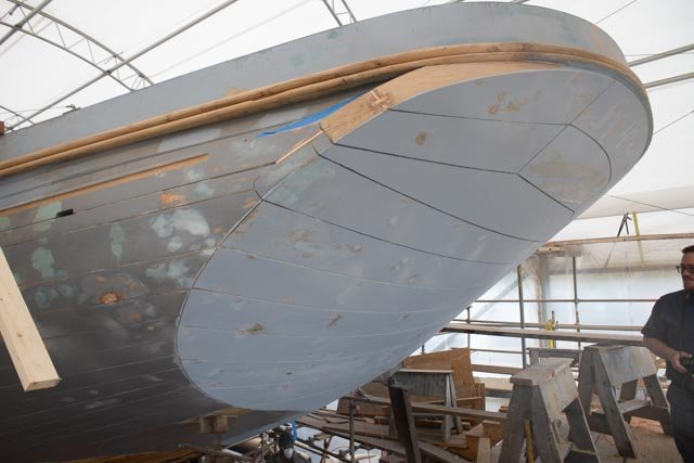 here we see the detail of the planning on the transom.
-
297
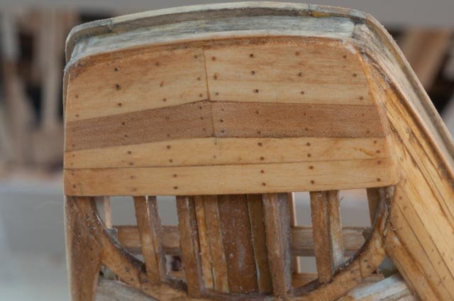 here is my attempt to replicate it
-
298
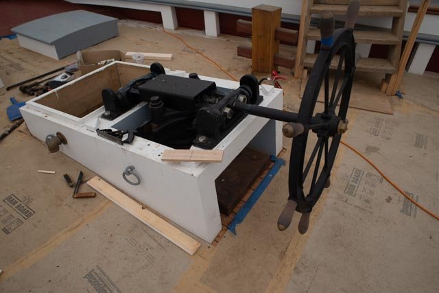 Here is the wheel gear box and access hatch
-
299
 here is my attempt to replicate it
-
300
 this view from the aft side.
-
301
 My next question is how, if at all, do I finish the wood. There are various stains and that could be enough. I often used either wipe on poly of tongue oil in the past. Once I do either there is no more ability to fuss with coloring etc. the decking is unfinished maple at the moment, and it needs something just to stay clean and to be cleanable in the future. I also must decide how much deck to install. There is no right answer I believe to that question, so I will see where it goes. I want to complete enough in the bow to show the two lazarette hatches. I need to get the scuppers in soon too.
The dock
-
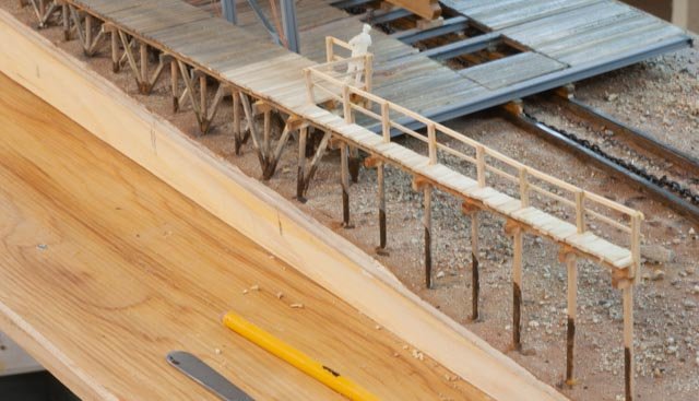
302
 this work on the dock needs to realistic enough to make sense but not take over as to the subject. I hope what I doing here works.
-
303
 as we move past the railway, the dock does stop for a bay and then continue out into the harbor with another building. I hope the sing sting of piles works.
-
304
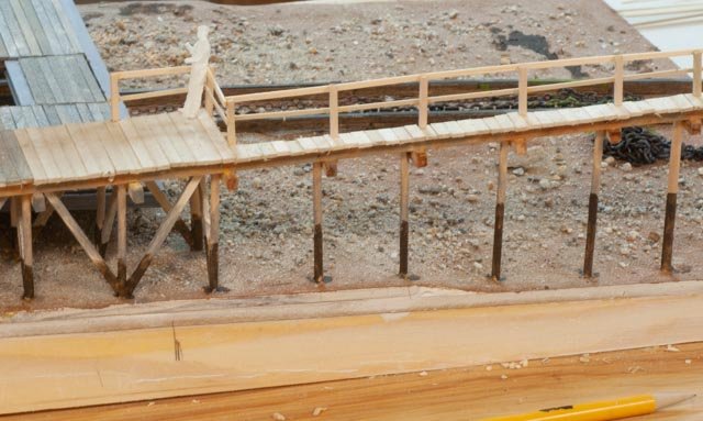 here I started to show the low tide makings on the piles. I also hope the handrail will help explain this line is the end of a dock that makes up the shipyard. We will need to have an over view phot top make that more clear.
-
305
 coming up soon I need to get into the seaweed and other things to help make the shoreline more realistic. That is actually fun as I have to invent my way through the stage and hope it all works.
Next up I need to complete the fore deck framing and get into decking. Then I need to set the first steel frame and platform and work on chains.
-
296
-
Post 28
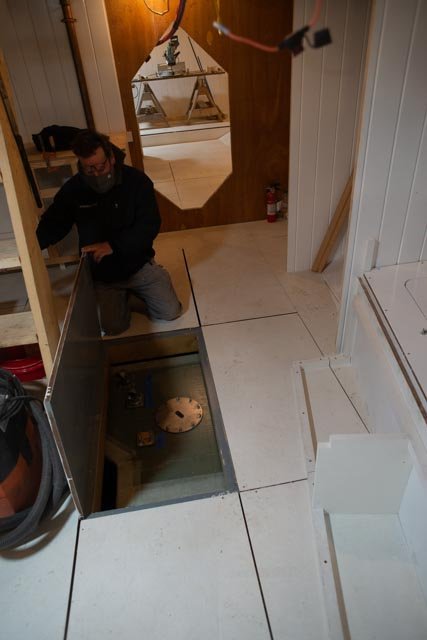
Progress on deck and the engine room hatch rebuild
This post records one of the challenges of building a model without proper drawings. The park service drawings for Ernestina were based on field measurements made in 2008 ish. The 2016 redesign and rebuild has many subtle changes. I am dependent on my observations and photos to pick them up.
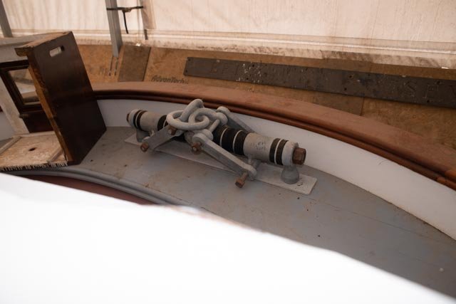
Recently I was asked for information regarding the pumps. I posted the photo below on Allanyed's site without much thought, as I am not building out all the deck furnishings. Now that I progressed as far as I have with the framing and deck beams, I started adding deck. I found something that did not make sense.
-
286
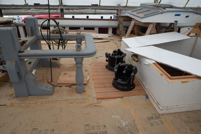 This view shows the new pump on the rebuild in a space between the main fife rail and hold hatch that is clearly as big as the fife rail. Let’s call it 4 feet.
-
287
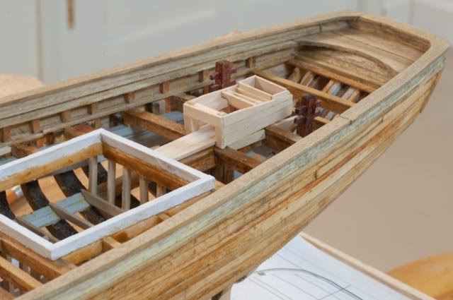
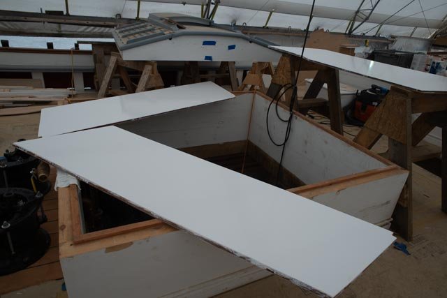 This view shows the engine room hatch/ dog house being almost square.
-
288
 This view shows what I built that clearly reflects the drawings. The hatch is big and comes forward to the major deck beam just aft of the main mast. This configuration may agree with the drawings but clearly not the photos of the new build.
I was lucky to get to the yard and learned that I not only did the hatch wrong, but the lower bulkhead should also be one beam aft of what I built, again as I built to the old drawing. I need now to dismantle and rebuild the hatch and bulkhead. That will also free up space between the major deck beams for the pumps and reflect the new build.
289
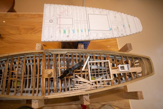 this view shows the deck plan with a red line where the forward extent of the hatch needs to be located The reduced size of the hatch would give room and clearance through the structure for the pump as well.
-
290
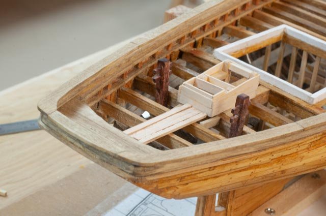
 This closeup shows the bulkhead below that needs to be moved aft one frame.
-
291
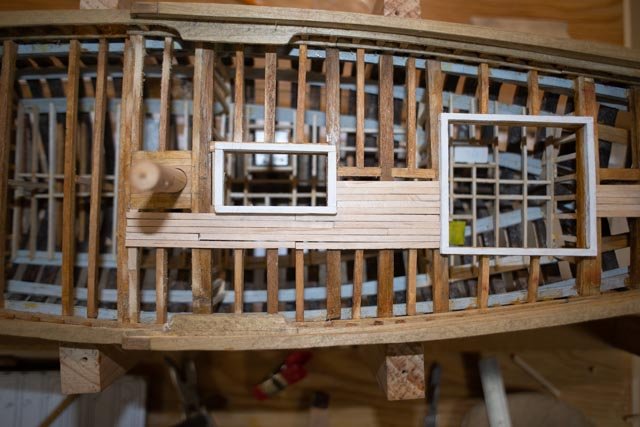
 Here I have made a new deck beam.
-
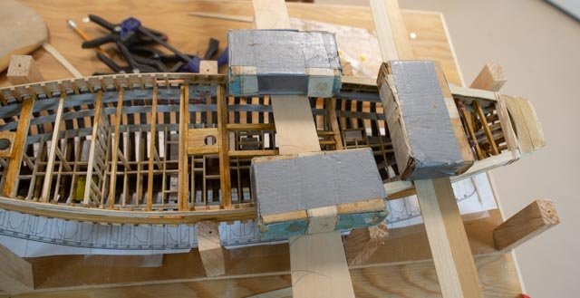
292
 In this view I have removed much of the lower deck frame and bulkhead. I may be able to reuse most of these pieces in the rework.
-
293
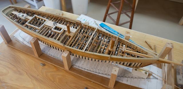
 Here we are all rebuilt and the deck recut and placed.
-
294
 Here we are a few days later where we wanted to be. The decking around the hatch is being glued down.
-
295
 I wanted to share this view of the real hatch construction. The hatch curbs are painted white. The unfinished wood is the buildup of the doghouse that as of now I am not building. I may rethink this later.
Well, I lost some time. Checking things twice pays off. Fortunately the rework was not too taxing.
All for now
-
286
-
Post 27
Diorama update on the dock and boat stands
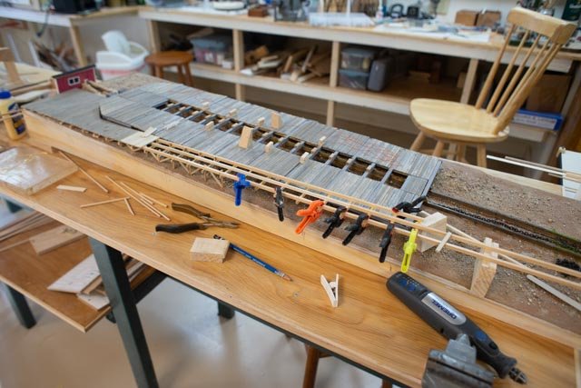
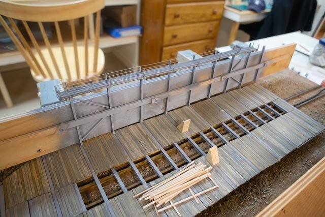
This posting records progress on the railway. I also want to share some more images of what the real equipment looks like and then my approach to replicate it in miniature. There is also a sequence issue that I will share below. What I want the observer to learn from seeing the diorama is how the railway works. First up is some progress.
-
273
 in this view the building of the structural steel towers has progressed to painting and has gone from the table. I have started the dock.
-
274
 as we start building the dock toward the harbor, the railway car deck is 2-3 feet above the dock. The piling starts somewhere under here.
-
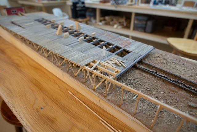
275
 as I work south, I need to make the piling reasonably realistic as one can see through from the side. I can promise this task is another rabbit hole.
-
276a
 at the top end I need to both close in the ugly side of the diorama for paint out and thought it would be good to show the front of the winch hose that pulls the chain.
-
276 b
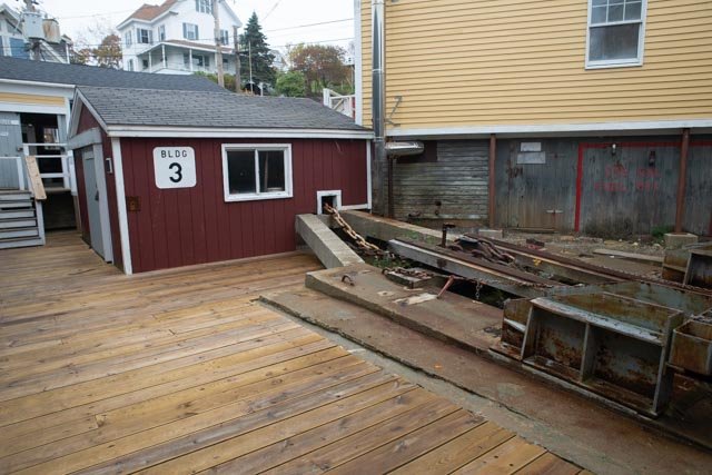 here is an image of the scene. The large 10-inch chain goes in and out around a windlass to pull the car either way.
-
276 c
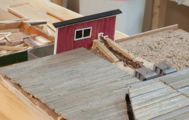 here we are with siding etc. I will add the sign
Ship stands are quite unique, and I want to represent them the best I can. The phasing issue is that while frames and exterior planking is underway, these stands are not in place. They go in after planking. I feel though the system is important, and I will explain it below.
-
277
 here is a complete stand. In this build there are ten of them engaged. The system allows for 8, a pair at each of the main columns in the structural.
-
278
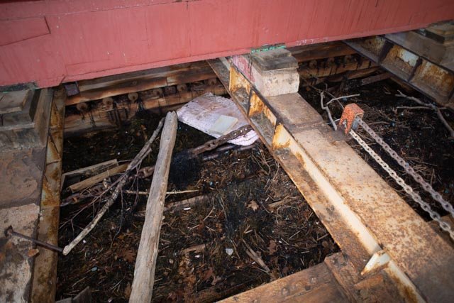
 here you can see the tabs that ride on the edge of the floor plank. The forward uphill stand connected to a chain that passes through the box sheave and runs on the near side of the beam across the car to the exterior. the chain on the far side of the beam connect to the outer corner of the block. These chains pull either toward or away from the ship [ schooner tug or other vessel when the car is in the harbor to either grab a vessel when hauling or loosen a vessel at launch.
-
279
 here is a better view of the chain that pulls the stand inward.
-
280
 on the outer edge of the car, the continuous chain feeds through two more blocks and upward to the platform.
-
281
 on the platform there is chain fall rig that grabs the chain and with a handle, when operated, allows a man to move the stands in or out accordingly.
-
282
 in this view one can see that all 8 columns are set up this way.
Now how to model this system …another rabbit hole. To do all eight that means 16 times 20 inches of chain. 64 blocks and attachment to ABS plastic steel. No soldering. I will go as far as I can reasonably…. we’ll see. I started by buying 20 feet of chain and raiding the last of alloy blocks from my Bluejacket stores. I will do at least the 5 engaged stands …again we will see what that looks like
-
283
 here we see the second side of structure just back from painting. I figured out how to do three blocks attached to ABS and thread the tiny chain.
-
284
 here I am trying to make the blocks to go at the car level out of ABS plastic so I can weld them in place.
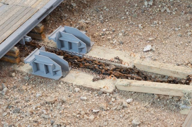
-
284
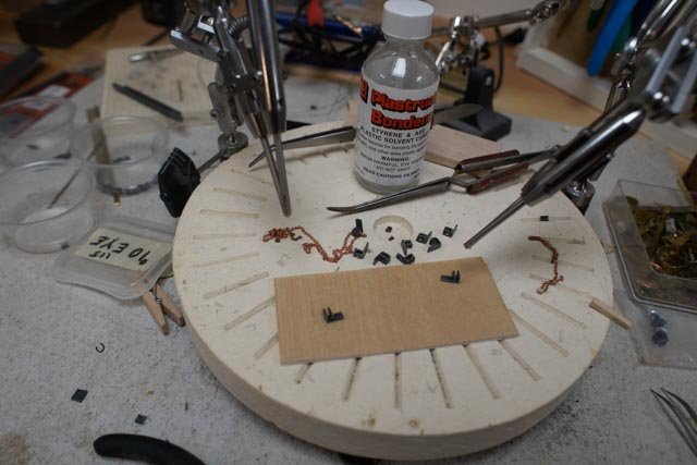
 here I have placed the bottom component of the stand where they go and laid out a 20-inch section of chain. The only way I can see to attach 42 link chain is glue. I made an eye that clearly too big so more work there.
I think it is important to tell a s tory about this 700ton-railway car. It has been here in some form since 1869. The history of the railway is being studied for exhibition by the yard and that is exciting too.
I probably should make one stand at a 1:12 scale as part of a side exhibit. More to think about.
All for now
-
273
-
Post 26
Progress on top rails and deck level
I am celebrating another small milestone this week. I completed the cap rails yippee.
-
262
 Here we are gluing in the outer band of the monkey rail. I had some scrap 1/32” on the outside resting above the lower cap rail to maintain the right shape and recess…. The outer edge of the two rails match up.
-
263
 here we are gluing in the inner band of the monkey rail. Two each 1/16” bands give us the 6 inch in scale rail.
-
264
 looking better. Now to do the cap rail. It is narrower but more difficult as it rounds to the main cap rail.
-
265
 here I took a piece of maple and started carving. it is a true trial and error approach for me.
-
266
 here we are carved, and it is time to split it on the table saw for two pieces.
-
267
 here is the port side from the outside.
-
268
 here is the starboard side from inside
Now what comes next and what needs more thought
-
269
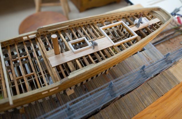
 in this view of the stern, I have placed a king plank. I plan to use maple for planking just to have some visual difference. Before I decide where to put decking, I need to build up curbs for the hatches, and things that interrupt the decking. I stared with the captain cabin and am now working my way around. I used a duller cherry stain only on the bulwarks again to show they are different wood. They are all Douglas fir as I understand it. So is the deck but it gets a very dark treatment eventually
-
270
 here we see the bow section. I have drilled the hawse holes and set up for the bow sprit. There is a king plank sitting there but ai am unlikely to use. The old drawings show no king plank and the photos I have show none. I am just used to them. the phot of the new deck clearly shows the stern to have none. Also, two planks in the middle fit nicely against he Sampson post. Sounds like a tail wagging the dog but something will be done. if i mount the prop bowsprit no-one can tell anyway.
-
271
 this shot was last Friday just laying out my supply of beams to see if I was ready to attack the main deck. I also had just installed the last few lower deck beams so that area is complete less construction planking and ladders. there is progress below on the dock as well.
-
272
 this is todays celebration. Other than the steering gear rig, which is in fabrication, the after-deck framing is complete. I have cut out the curbs [ kerbs] for the next hatch and they are in for painting white like the captain’s cabin curb. The plan above shows I have used the 2006 measured drawings as the basis. The were no noticeable differences going through the current rebuild so we should be OK.
Next up I will continue forward on the deck frame and building of the diorama dock
cheers
-
262
-
Allan
I just found this posting, so I understand you email
I will post photos on how down hauls are tied off on my Bluenose log. I am restarting that to complete sails and that will include gaff down hauls
Main gaff has both p and s going to the rails
Fore gaff drops straight down to starboard fife rail
Cheers
- allanyed, thibaultron and mtaylor
-
3
-
This posting is to record the progress as I pick up this build and carry it to completion.
When I left this work in august 2018 the model got to travel around on pillows in the back of a pickup to two showings. We since have gained an open yard trailer that lets her lay flat and go under cover if need be. She was moved in November 2020 to this new house and has patiently waited for her star to rise again. My Daughter came for Christmas as Covid-19 has truly limited mobility. She was here for a work week and play week. Can you imagine…go to the coast of Maine and work through your computer as if you are still somewhere else.
Anyway, the point is we decided to start the process to complete three upper sails and to replace the main sail and jumbo. Their replacement needs were well documented earlier in this build log and the question was both motive and time. My daughter took on the job to take the old mainsail and replicate it. Then she added the in-scale bolt rope and helped in any other ways. I started to commit a few hours a week away from my other build to plug along.
Today, I like many others have enjoyed getting into an exchange with other Schooner lovers about how certain lines are made off. As this build records, I made two trips to Lunenburg and took oodles of photos in high definition, so that I can blow them up and check many things out. So, I answered the specific question but choose to document here the findings as I too want to have those lines included on Bluenose. I recommend anyone reading this log to jump over to the build of the Effie Morrissey 1898 by Allanyed. In doing so, you will find a beautiful schooner being rigged for fishing at the same time. She fished from 1898 to 1925 mostly out of Canada with that rig which is contemporary with Bluenose
Therefore, for the record, I resumed work Christmas week 2020 to complete sails and running rigging hopefully by summer.
-
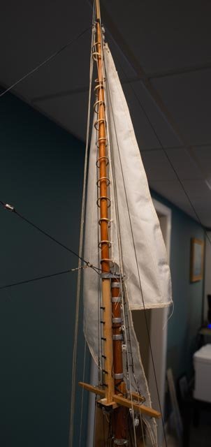
1101
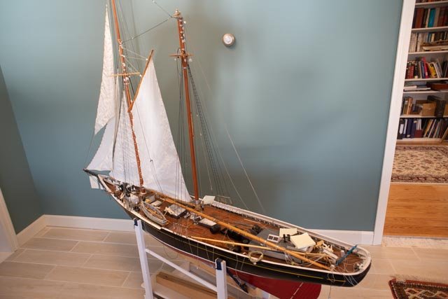 here she sits in her new home missing the old mainsail. If you look closely the main top mast is off too. While she sewed the new sail, I was in the shop making more hoops.
-
1102
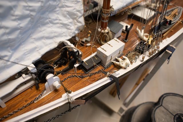 here if one looks closely there are broken parts on the windless and probably missing pieces from the moves
-
1103
 here we see the old jumbo. It is the only remaining sail. As for most of us, if we make one or two of something and then compare it a to the third and forth made a few years later, there is likely a need to rework or to replace the older version. We will see when we get to that sail. First to the others
I had made up the three topsails in 2017 and pinned them to the model while on display as seen in photos above
-
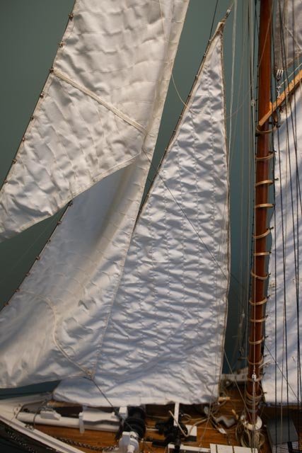
1104
 here the main topsail is in place. The tack lines and clewline are sewn in and coiled, ready for rigging after the mainsail is set
-
1105
 here the hoops are sewn to the sail. I had to add three hoops to get the number right…a lot of extra trouble. I can’t remember how I missed that before I fixed that mast.
-
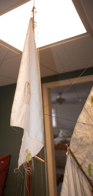
1106
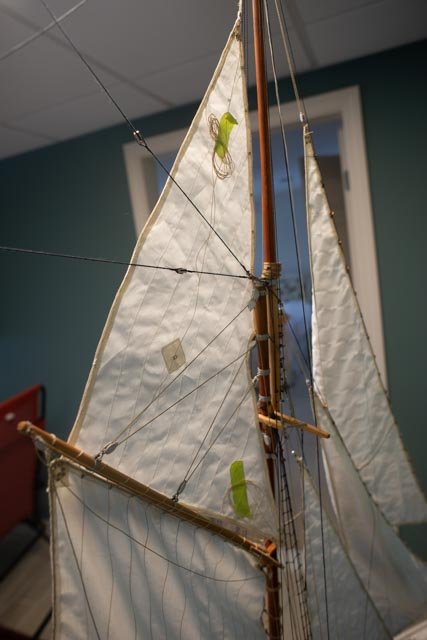 yesterday I finished adding lines and hoisted the fore topsail. Next week the hoops get sewn.
I am working Sundays on this project so it will take some time. also there is no running rigging or sails on my other current build, so this work is refreshing. I did some research on the gaff down hauls and will post that next time. I believe the clewlines act as the down haul for these two top sails. And the jibs are all in as well. That leaves the two gaffs to rig, so as I attach the top sail sheets, I will need to splice in the down hauls to the ends of the gaffs.
All for now
- allanyed, GrandpaPhil and KeithAug
-
3
-
1101
-
Allan
no sail plans yet for EM. One more detail I suspect is there were more connections in the stern. I again take my learning from Bowdoin arctic rigging and Bluenose with its large size. There were quarter tackles to secure the boom, the topmast backstays were made aft for the upwind side and last pin behind dory tackle on the main mast for leeward side. There were down hauls on the main gaff peak tied off to Starboard. Also several lines both on the rails and the fife rails needed snatch blocks on deck to allow a few men to grab the line and pull and then take it to a pin to tie it off. We learned that while sailing on Bluenose. I believe there is no need for all the travelers on Effie though. For sails like the fisherman's staysail, they were flown from the deck per tack. the tack lines and all add up to more pins. The halyard was continuous and that means two more pins and deck block. Main and fore halyards were continuous as well. I only made the pin rail according to the drawing. if i were going to fly sail I would add several pins. I would move flag halyards to the shrouds etc. like on a ship. i wish you the best in the challenge.
I am grateful for the park service drawings but remind us all that they are measured drawings made after many tough years of packet service and ultimate return to US in sorry shape. I agree with you and other commenters above that Chappelle and other Gloucester/ Essex Schooner info is the best source.
I typed this much because it is 18 degrees outside.
cheers
-
thanks John
Allan
here is the buffer. I am very happy you are doing it. I am modeling pre paint, so I think home free without deck furniture. the railway is definitely adding more scope though. I went back up on deck to see if they have a horse. that would mean to my understanding that after back and forth to the buffer they come down to a horse to feed the port side bitt. I did not find one. To be fair to the yard, they are still waiting on the rigging design. new masts etc.
also my visits need to be delayed a bit.
cheers
-
Allan
i love your work...so clean and crisp.
I am just catching up on this saga of pins and cleats on the boom. It may be a stretch, but I learned a lot when I researched Bluenose for my build. I went to Lunenburg twice, spoke with the captain, sailed on her etc. He pointed out things of difference on Canadian schooners, but they did not include this subject.
There is a great resource I bought while there, The measured drawings on Bluenose LL by L B Jensen. He had taken, as I understand, information from the original 1921 as a basis. Also, there are numerous photos of the original online that I used. The Captain told me running rigging has not changed other than material upgrades.
The book of drawings clarify as follows:
- Pins in the yoke of the main boom clearer take both the Boom Tackle [ guy] on the starboard side and topping lift on the port side.
- As to the ring forward and below the boom….if I understand correctly....The yoke rides on what I unknowingly call a table or boom seat. Below the table are two bands with forward attachment of a small winch. I assume [ guessing] it was for using the halyard whips to snug up sails. The new Bluenose II , which is actually Bluenose III as like Ernestina she was completely rebuilt again about 10 years ago, has nothing below the “table…boom seat”. Another possibility was to place a snatch block there instead of on the deck for taking halyards or whips. We need to remember there is, nor ever was, a motorized winch to raise those heavy sails.
- Flag halyards on the Bluenose drawings are pinned to the forward most end of the port and starboard pin rails. One on either side [ two more needed pins.]
One of my concerns looking at the Ernestina park service drawings is the lack of pins on the rails. There are more lines than pins for complete running rigging, dory tackle etc. and no place to put them. Good luck .
jon
-
Post 25
How to finish the outside
Now the cap rail is going on, I need to figure out the final finish for the exterior planking vs. frames etc. First up, let’s get that cap rail done.
-
251
 I continue to use milled poplar for this build. The rail is marked and cut out of ¾ inch strips
-
252
 The mid-section includes the pin rail for the main mast.
-
253
 here all rail sections are on and ready for shaping. I used this process also to build out the fan tail.
-
254
 at this point, I feel we are starting to look like a schooner. The rail makes so much difference.
Now how to finish, and what to show
-
255
 here I tested an attempt to drill and plug holes for trunnions on the left column. No good and too big and way too much work for the result. The second frame to the right is simple, smaller holes drilled and rubbed over with stain to fill the holes. Some sawdust was included. This is the way for me and now let’s get it on.
-
256
 on this attempt of the lower planks, I tried applying shellac to better fill up the holes.
-
257
 in this view I only used the golden stain and I like the results more. It is a subtle indication of trunnels. I was lucky to have earlier images, previously posted, showing the pattern.
-
258
 here I have drilled, resanded and restrained the starboard side. This view from aft also shows the transom upper half now planked as well.
-
259
 this view from the bow. Note I have fit a bowsprit to help complete the bow.
-
260a
 here in 2 stacked photos, the whole set up is clearer. One can also see progress on the port side steel structure for the railway.
- 260 b
Next up more railway progress
Cheers
- Richvee, Roger Pellett and allanyed
-
3
-
251
-
Post 24
Steel work coming along and a need to plan docks.
Every day that I can work on this project I have been adding more and more inside. I believe in another week or so I can stop. In the meantime, I need to finish the basic hull construction, so that I can finalize the finishing process. The railway could either stay simple or become a real rabbit hole. I am going through the process and will share my thought process.
The hull
-
241
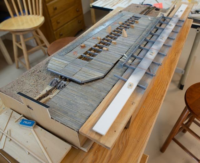
 this shot is intended to give a progress view of what the innards will look like. I have a dozen or so more lower deck beams to install and then decide what to do about its decking. After that phase I will complete the main deck beams.
-
242
 this photo shows the build out of the lower deck. The deck beams are often removable, and all of the panels of marine plywood can come up. Here we see a waste tank. There is still 60,000 pounds of lead ballast to be placed, and access to below decks will be continuous. There will be fir decking over these panels at the very end of the construction. In some earlier photos we saw plywood laid out for working platforms during the construction. What I will try is to place a few sheets to reflect that purpose and temporary construction planking to support a few construction ladders.
-
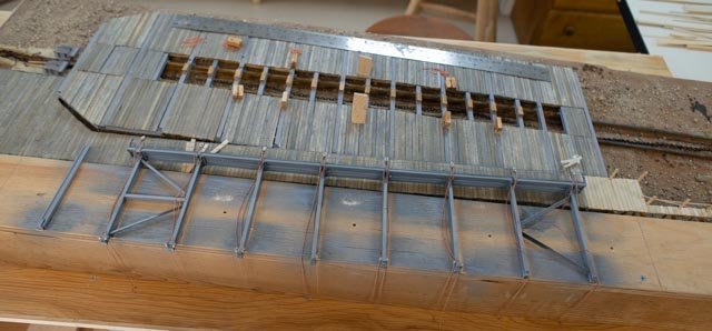
243
 I have laid out the first cap rail and will be fitting it next, as soon as all the waterways are in. I have started with the transom area and that also shows in the following photos. I hope to clean that up for next time.
The diorama
Lots of progress this week. The first stage was humorous.
-
244
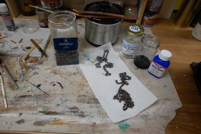 I upgraded my blackening equipment this year to include the little slow cooker for better temperature while pickling. I then went to Michaels and Joann’s and bought several sizes of chain. What I found was a mystery material from china. I tried it even though it was magnetic, and to no surprise it did not work. I did get some form of coating off because after the whole process including the blackening process it was quite bright.
Off to the garage we went for spray paint with auto primer. That worked nicely and then I am using a combination of artist acrylic to simulate the variety of colors. Rust, slime seaweed paint spills etc.
-
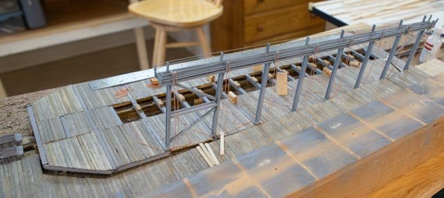
245
 also off to the garage to spray out the ABS steel frame. I am happy with it, but I ran out and the next can is a different shade of gray…….oops
-
246
 here we see ABS gray steel, painted chain and the beginnings of simulated concrete.
Next up is the blocking.
-
247
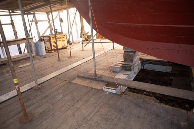 here is the most complicated one. It will surely go in last.
Overview
-
248
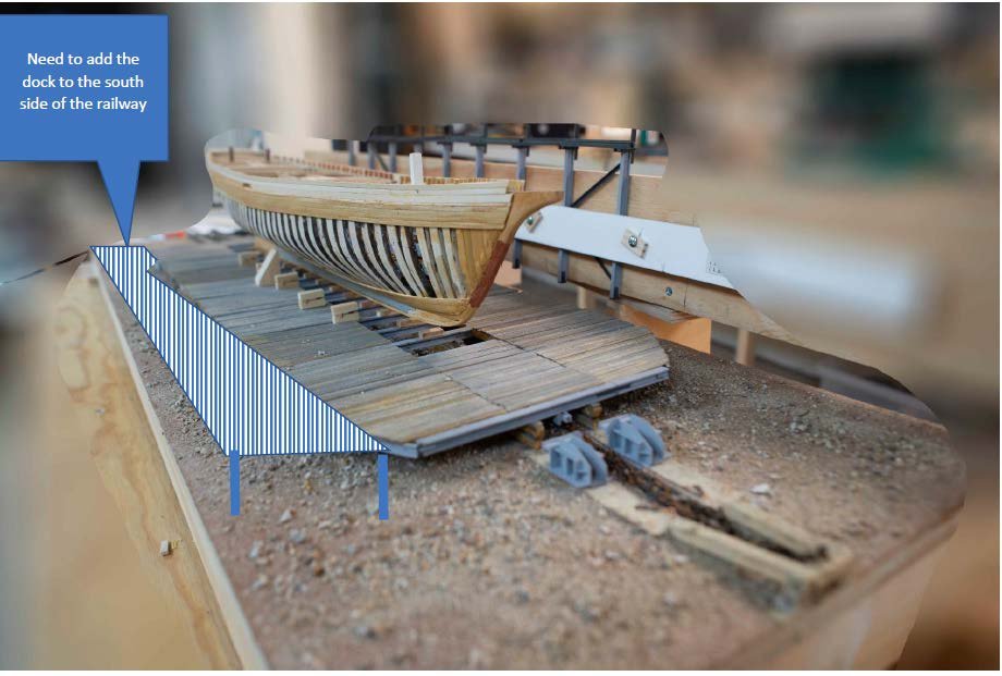 here we are sitting on new blocking with the second side [ north] steel frame being assembled. I added to the photo where I need to decide if I am going to build the dock, I think I will at this point
-
249
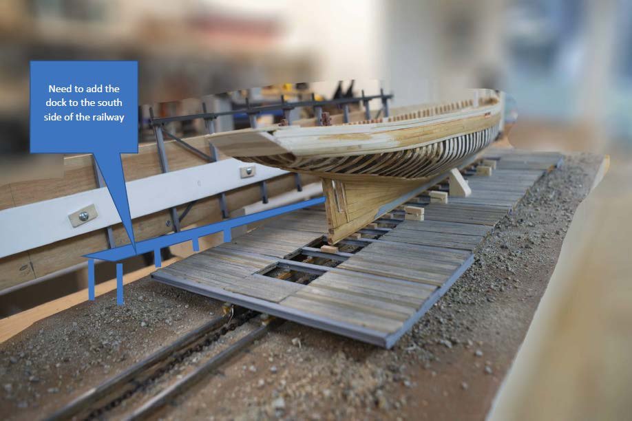 here we are looking from the west end. The transom is coming along. It is clearly the most difficult part. The chain and track and soil at this end will need more painting and seaweed. Again, I show the dock that I plan to try to do.
-
250
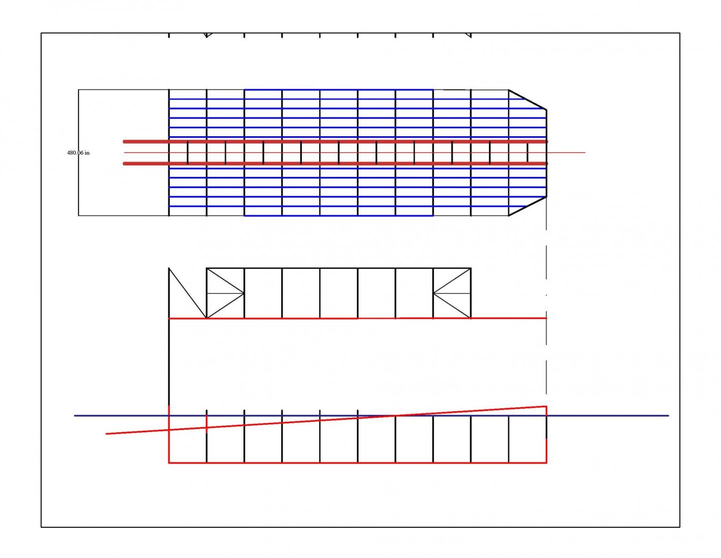 this drawing shows my figuring out how to make the slopes work to fit the dock to the railway properly. I have several photos and believe I can get it right. I must slope the existing diorama about 5/8” one end, so the red slope fits a level dock.
All for now
-
241
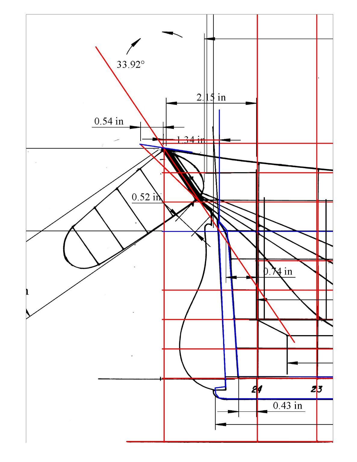
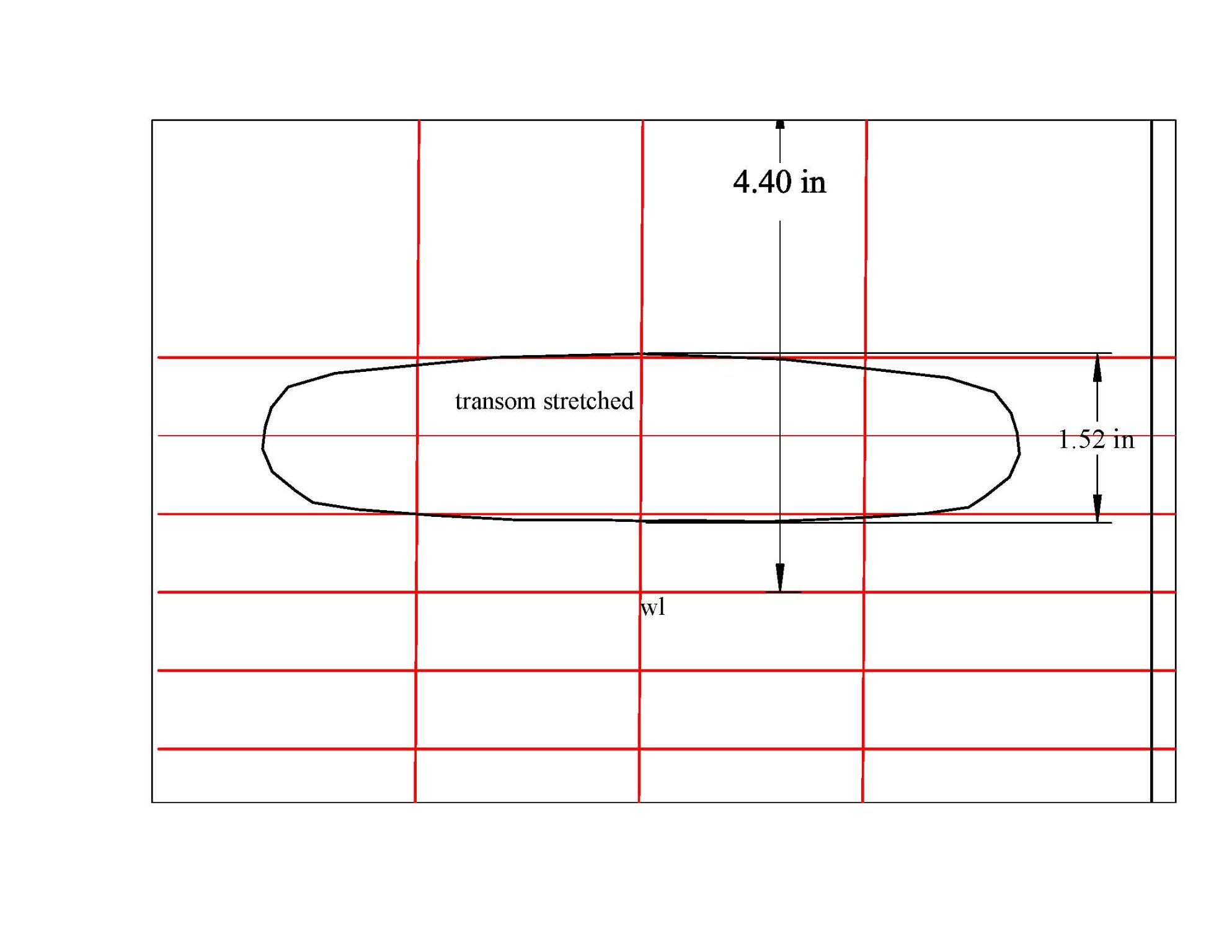

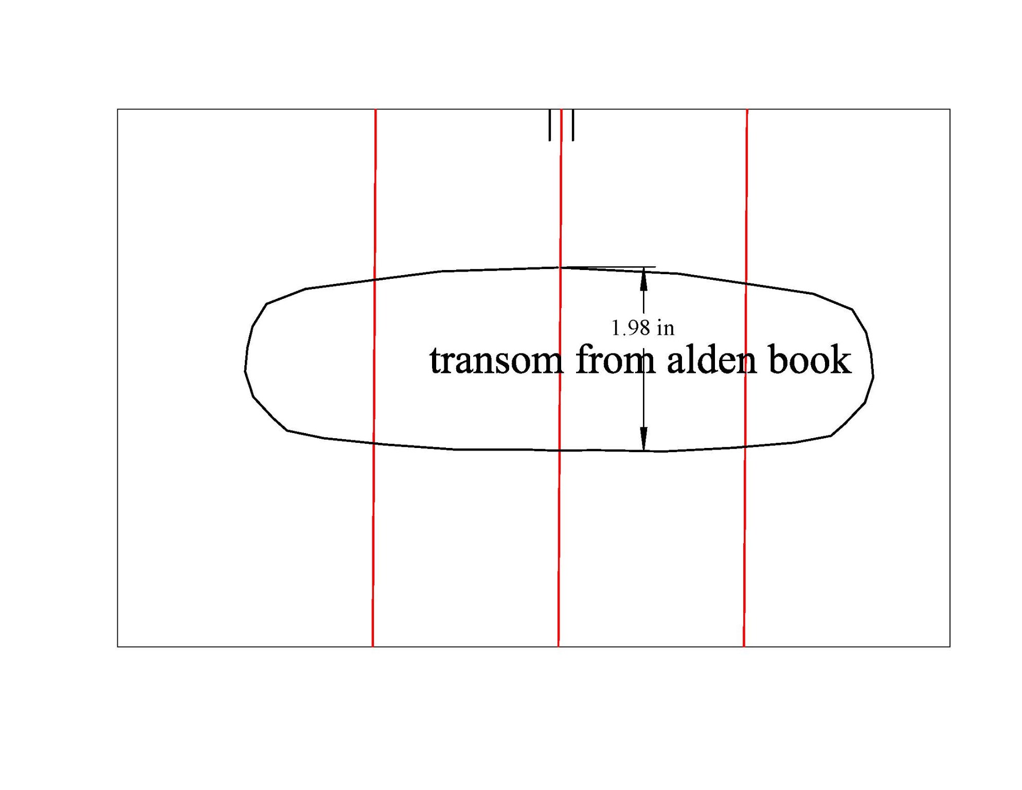
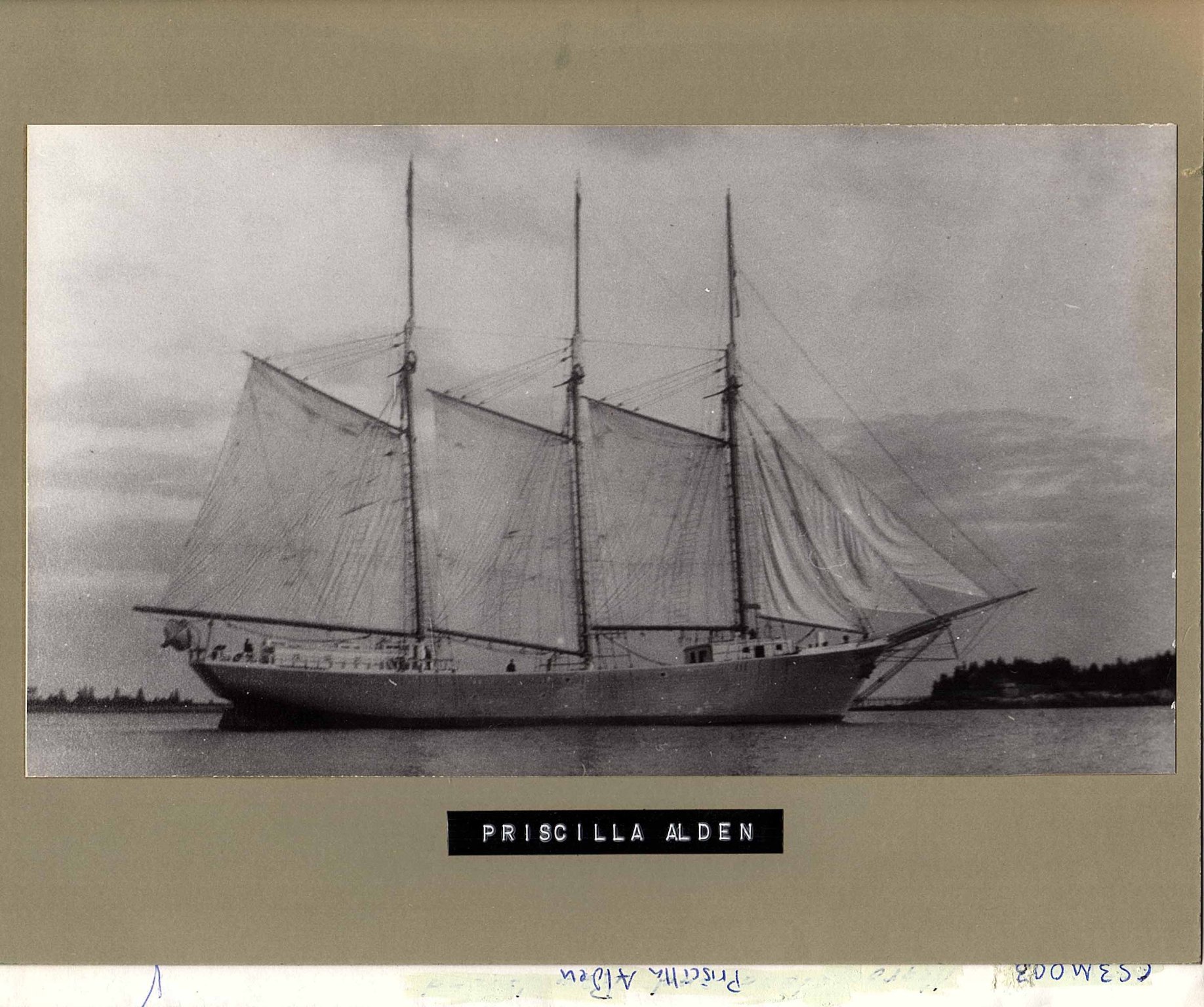

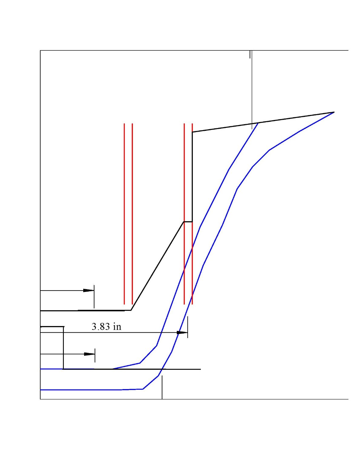
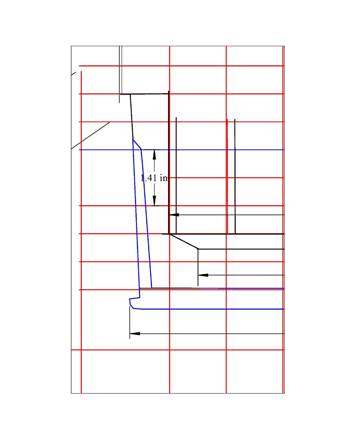

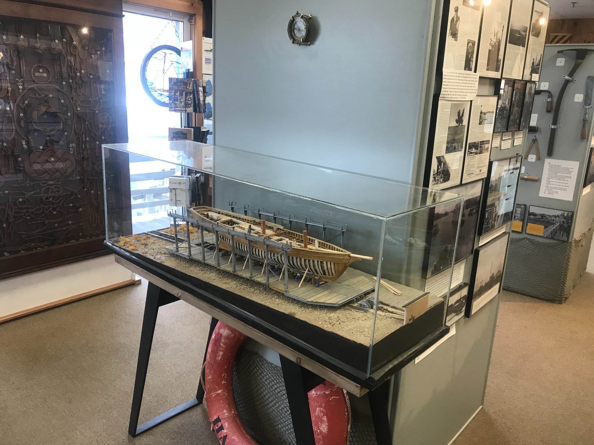
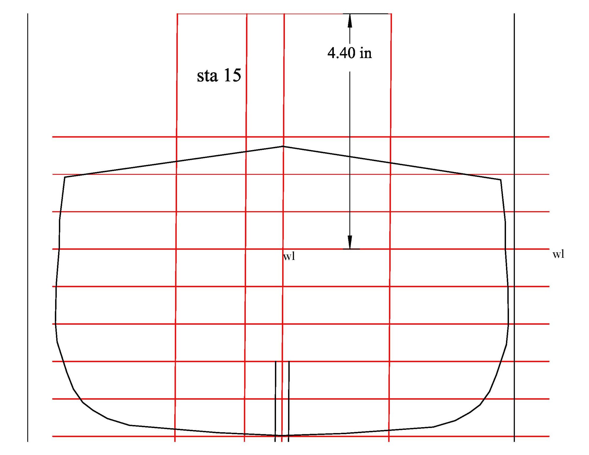
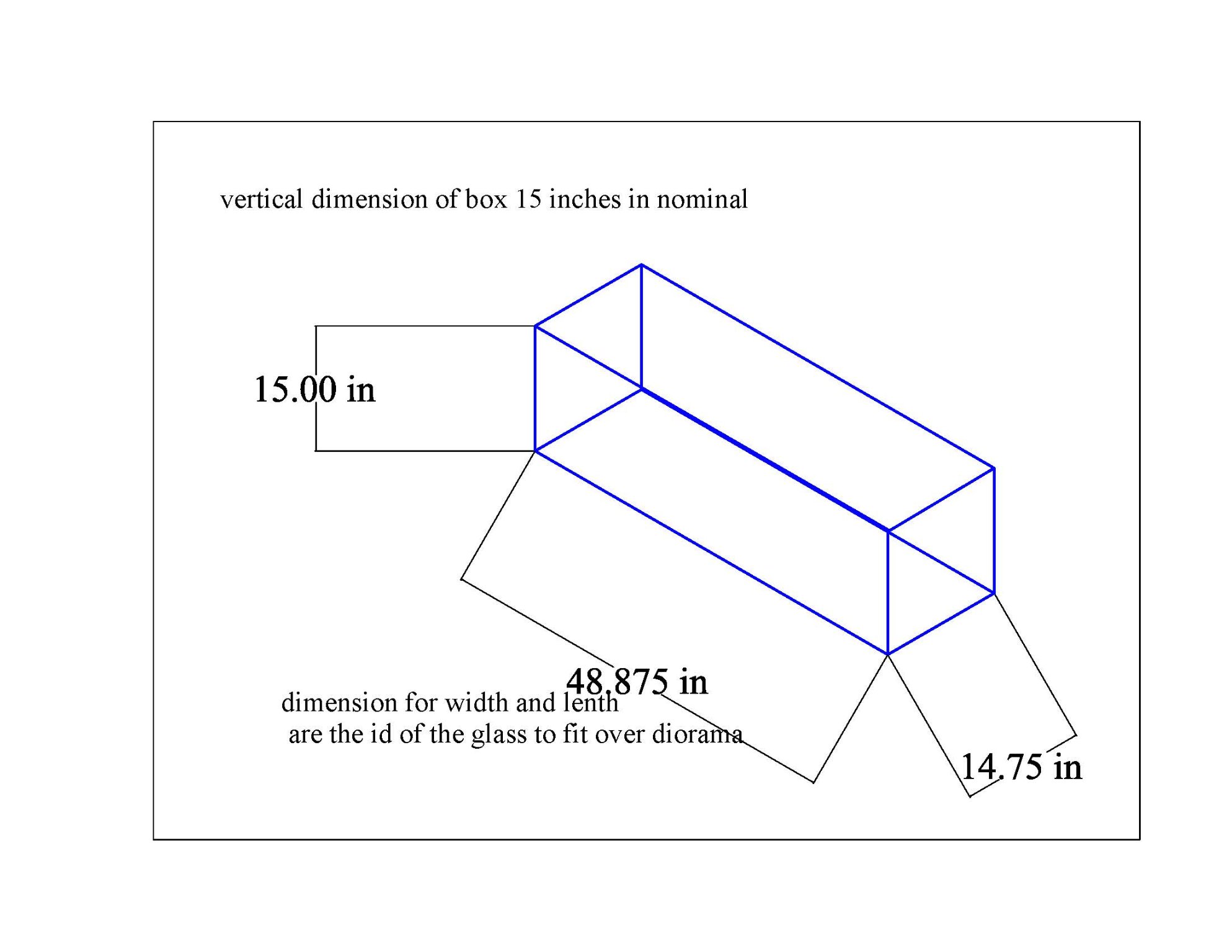
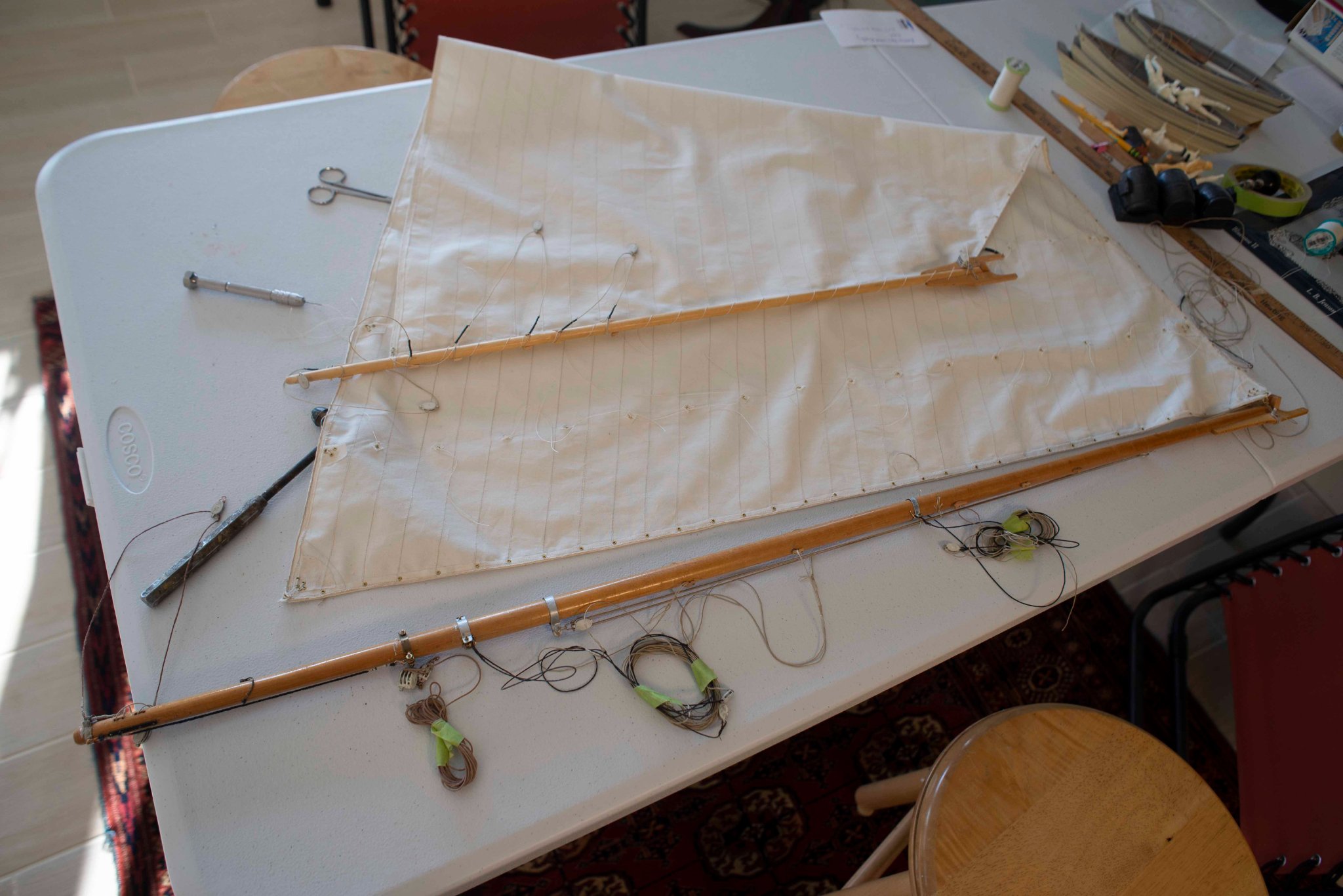
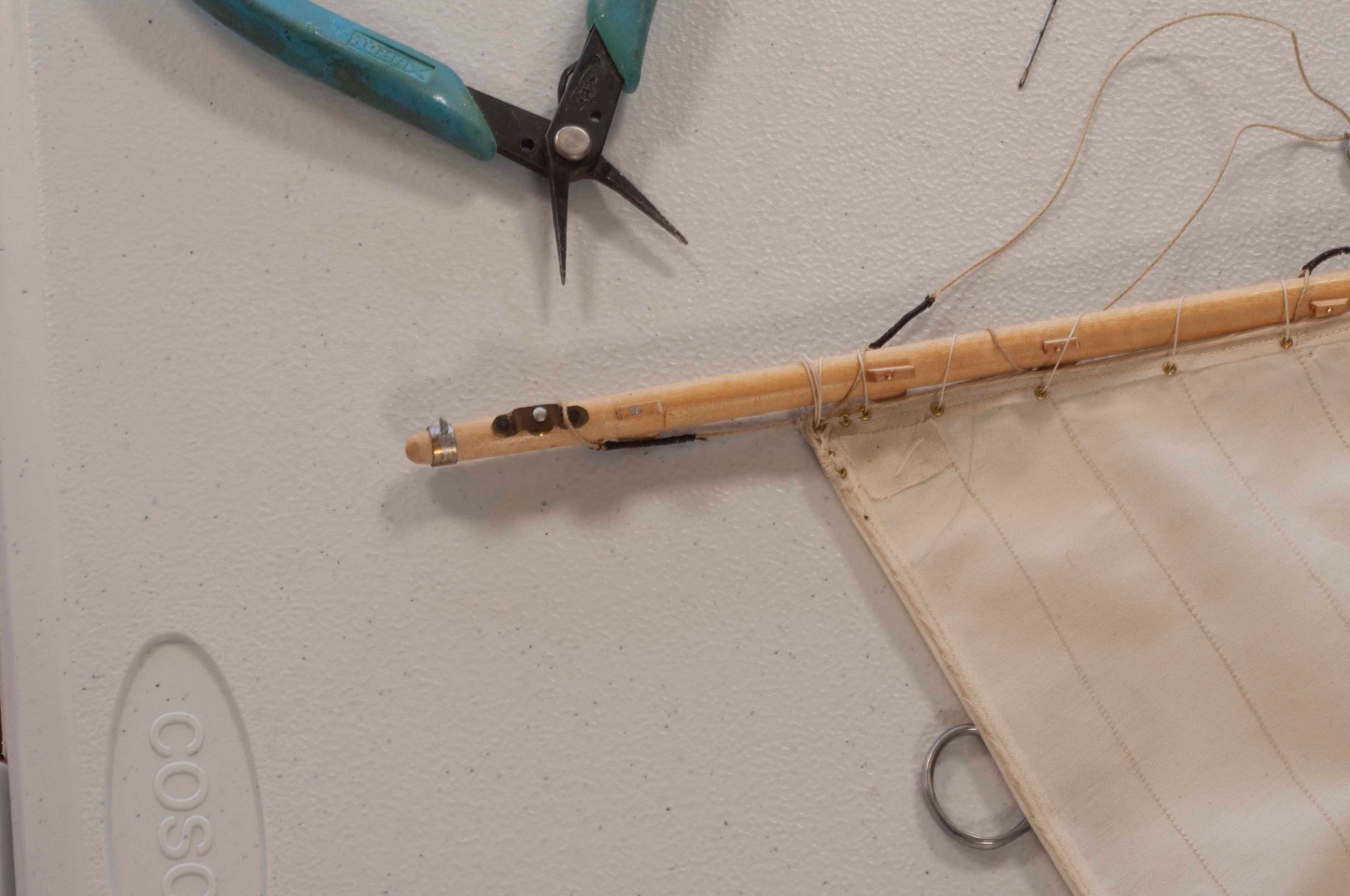


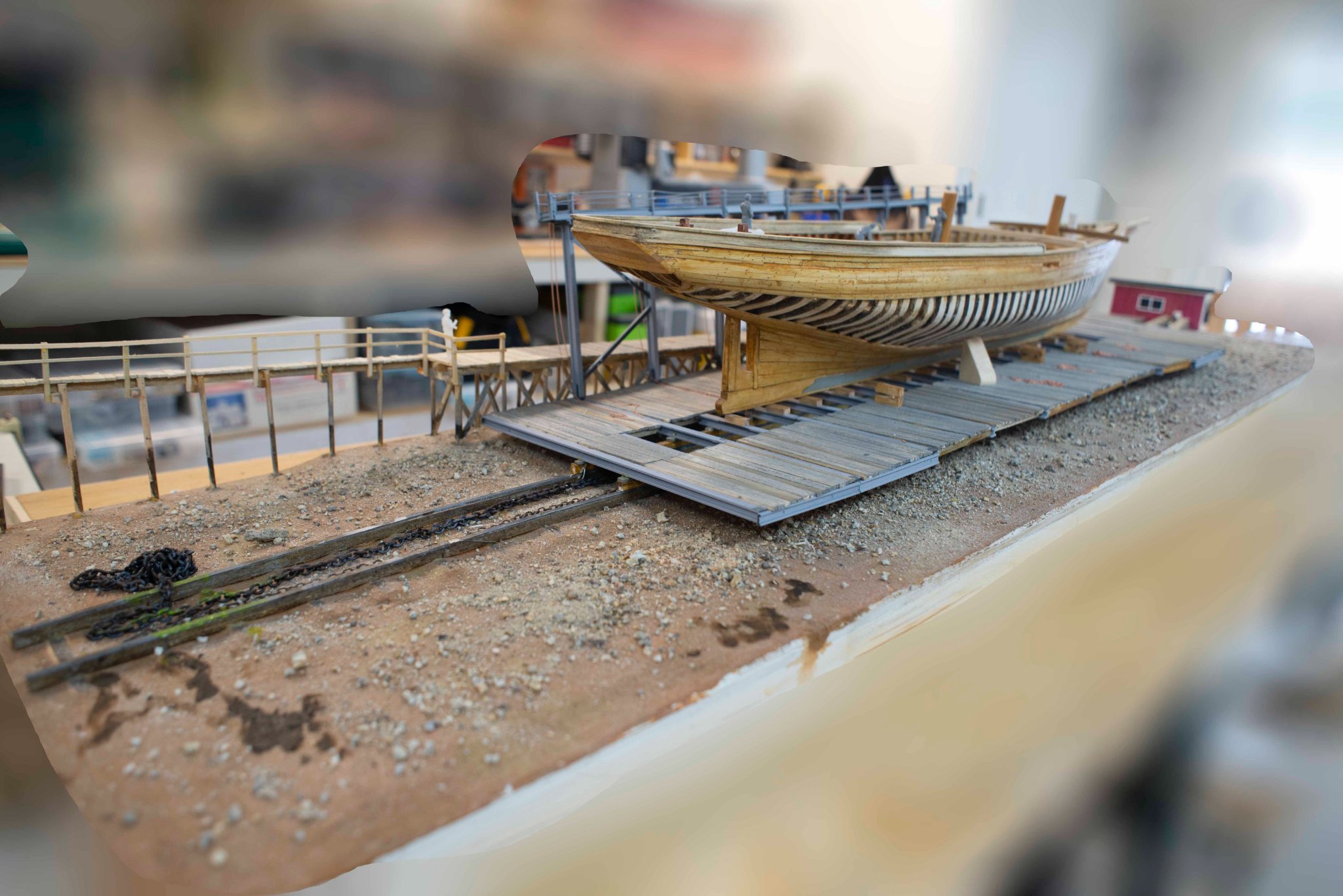
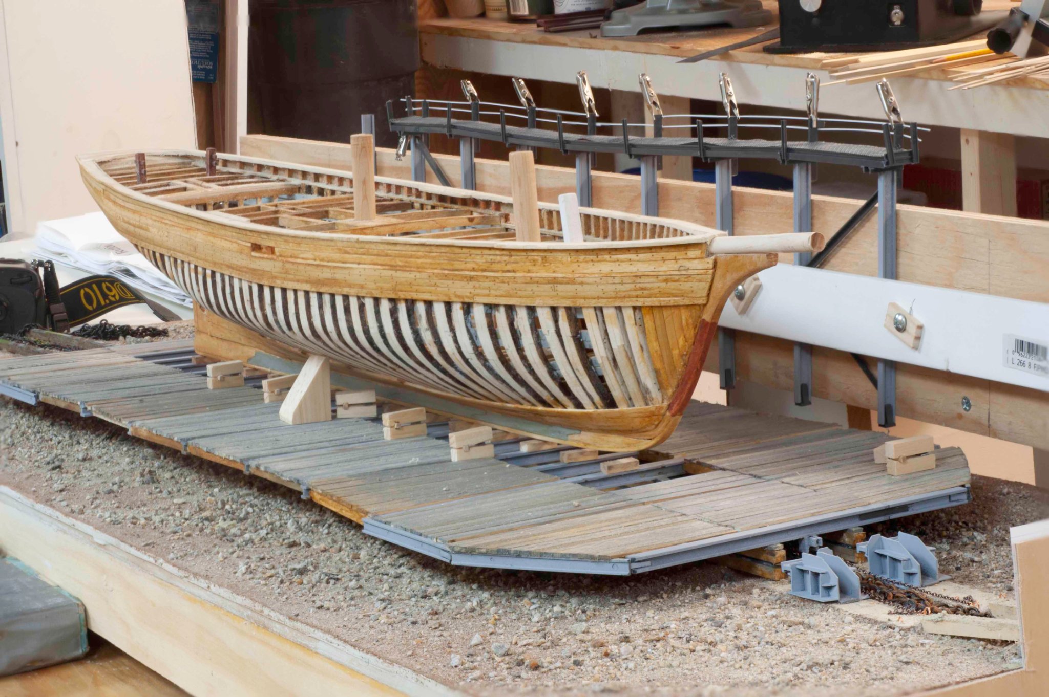
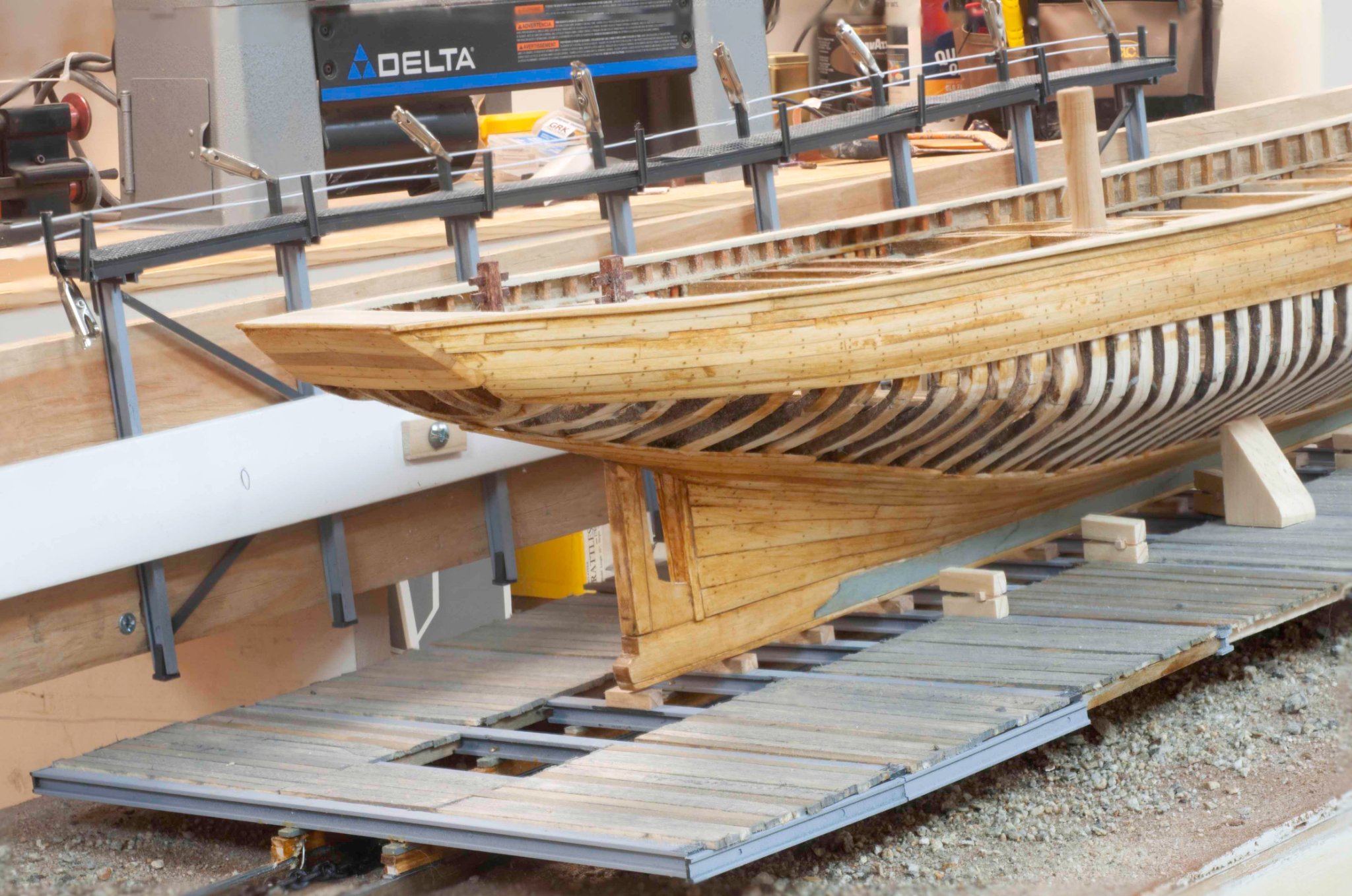
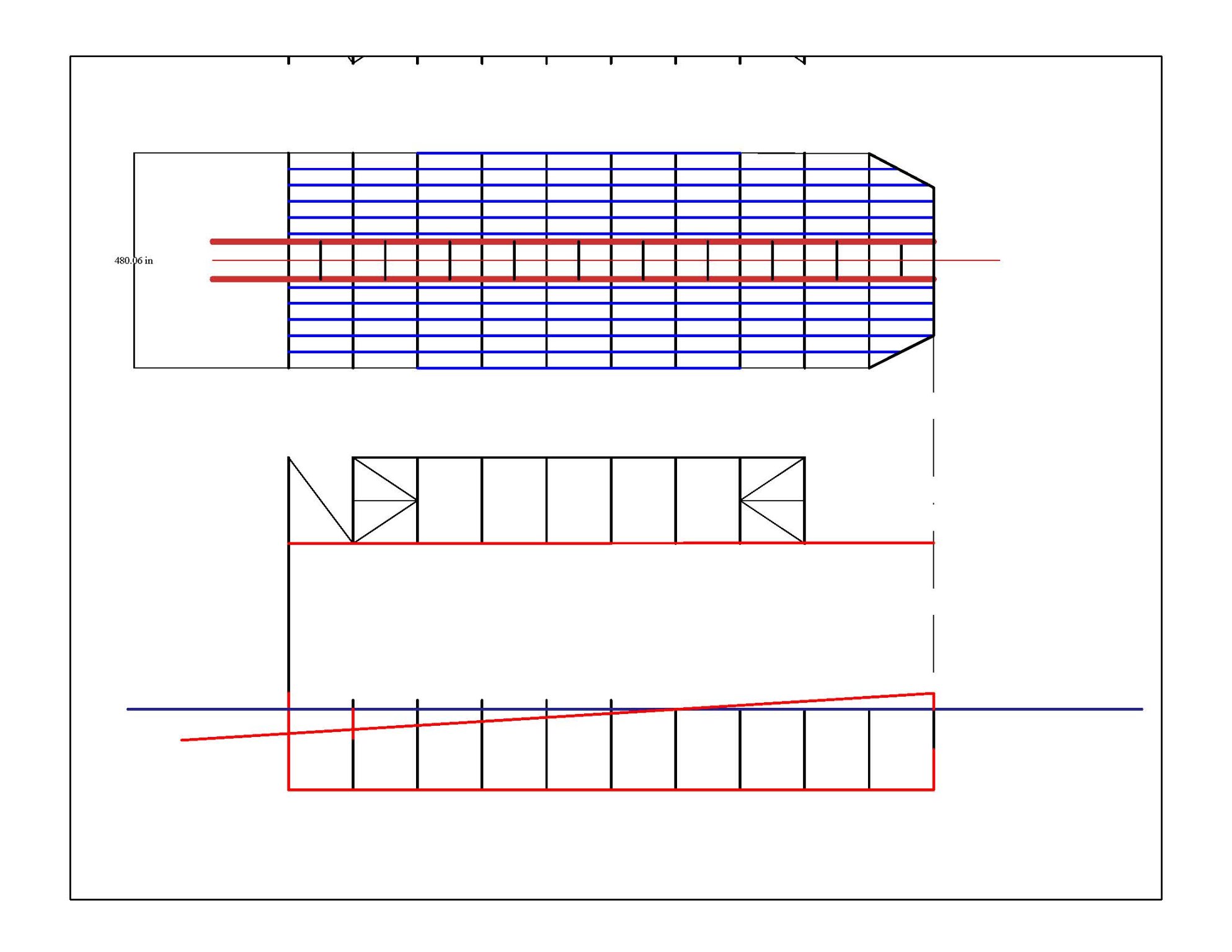
ADA CLIFF 1918 by Jond - 1:48 - three-masted Boothbay Schooner
in - Build logs for subjects built 1901 - Present Day
Posted
Post 6
Complete deck shear line planks
I have to admit that I am going back and forth between drawings of schooners and playing with the few photos to make some of the design decisions needed to move forward. One example is to identify the location of the forward end of the poop deck. In the 1894 build of the Charles Notman it was unusual and went up forward past the main mast. That was found to be not a great engineered solution and was quickly abandoned. The 1917 Priscilla Alden plans that have survived are the general basis of the logic I am using. All that being said, the point is we are building a bulkhead model and need to be sure to eliminate the bulkheads at the deck level before planking where possible.
Using the Priscilla Alden plan, the poop deck ends just forward of the mizzen mast. The fore deck is raised just forward of the fore cabin. The foremast is in the middle of that cabin, so one would go forward stepping down to the fore deck.
I probably did the extension of planking for future connection because it will make a much stronger model. Perhaps a carry over from my radio sail days. These 1/16” poplar planks will be quite strong. I do not plan to use resin on the outside because I want to see the planking through the white paint. I am not sure yet how much of the bulkhead I will cut out after I turn the model right side up and start the deck.
Next up is to figure a planking plan