


AON
-
Posts
2,792 -
Joined
-
Last visited
Content Type
Profiles
Forums
Gallery
Events
Posts posted by AON
-
-
NOTE: MY PARTNER IS WRONG AND WILL BE CORRECTED AFTER POST #1711
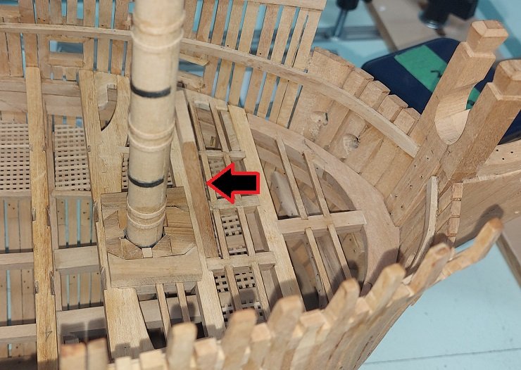
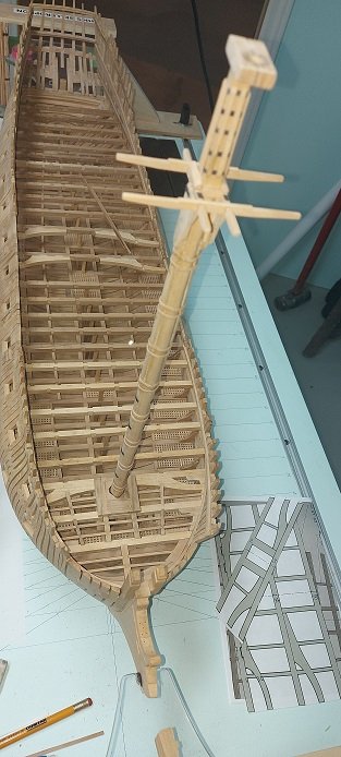
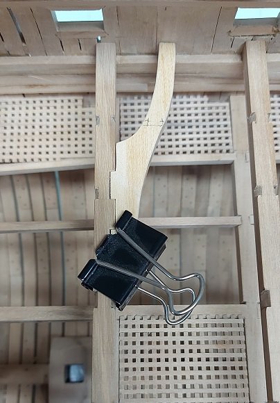
Made the replacement partner and dry fitted it on the deck beams with the foremast installed and the bowsprit step set on the beam and its present extra length leaning on the mast. The arrow points to it as it seems to blend into the background at this angle.
The step is not finished as yet. It needs some sanding and rounding off the four top outer edges.
It will also rest slightly forward of where it is now but I need to make one upper deck beam to support the bowsprit step so it can be cut to length and prove the assembly location of the foremast partner.
That is my next item to make.
I didn't call it a mast this time!
But I will ....
- fake johnbull, davyboy, mtaylor and 7 others
-
 10
10
-
-
Thanks Tom but I owe it to the masterful drawings in TFFM volumes that I copied from.
I sanded down the forward end of the partner, and after placing it and the bowsprit (mast) step I decided I could do better. By the time I do the partners on the weather decks I'll be a professional! The new stock is sanded to thickness, cut in half and rubber glued together. I'll rubber glue the templates on tomorrow and then cut the pieces out for assembly.
Let's hope I don't screw it up.
- druxey, mtaylor, Thukydides and 2 others
-
5
-
-
-
NOTE: MY PARTNER IS WRONG AND WILL BE CORRECTED AFTER POST #1711
Some images from my making of the Gun Deck Foremast Partner
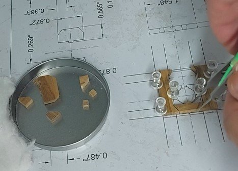
First is of all the various 10 pieces. I have a cork board I can pin pieces to.
I laid my plan on it, a layer of clear plastic over top and pinned my parts down onto it.
The plastic keeps the glue from sticking the part to the paper.
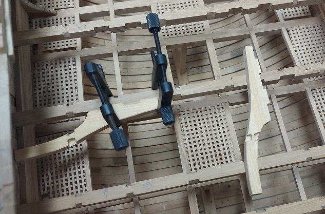
Then is the partner assembled and placed on the beams (dry fitted).
NOTE: MY KNEES ARE INSTALLED INCORRECTLY AND WILL BE CORRECTED AFTER POST #1711
Next a fitting in place with the lower foremast. It just slipped through with minimal clearance.
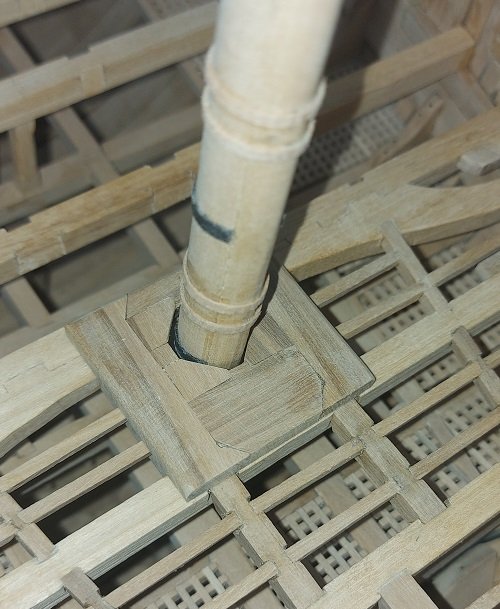
Problem being the forward part of the partner should be 1/16" or more back from the forward edge of the beam under it.
The bowsprit mast step needs clearance here.
I could sand it back. With the bowsprit mast step leaning backwards over it and the mast itself in place and two decks installed above I suppose no one will ever notice the slight "fix".
Or I could just do it over.
I'll let you know what I decide.

-
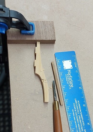
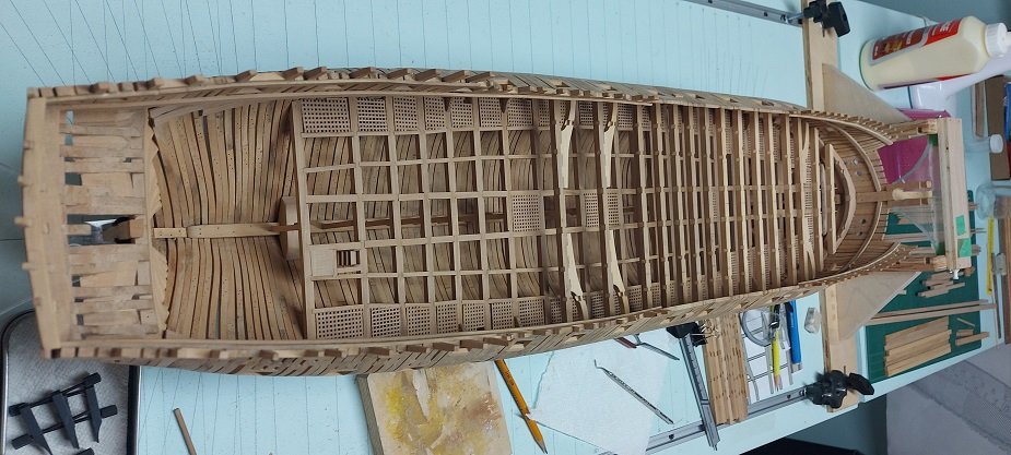
Cutting and fitting the carlings. ledges, lodging and hanging knees is slow going.
Might have a lot to do with distractions!
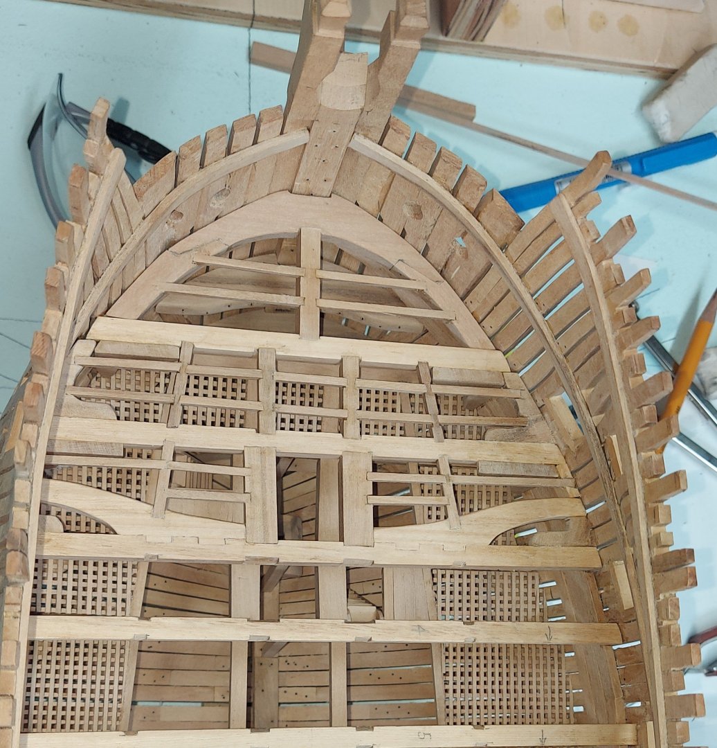
As I work back I'll be adding some additional pieces.
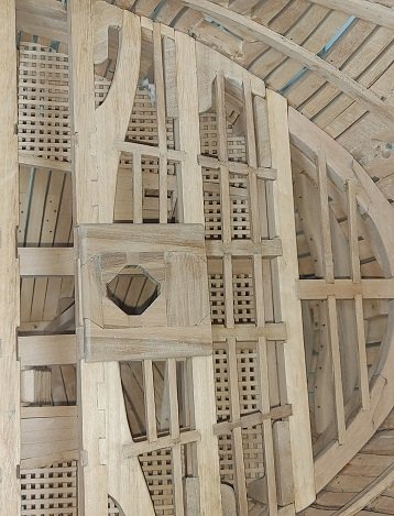
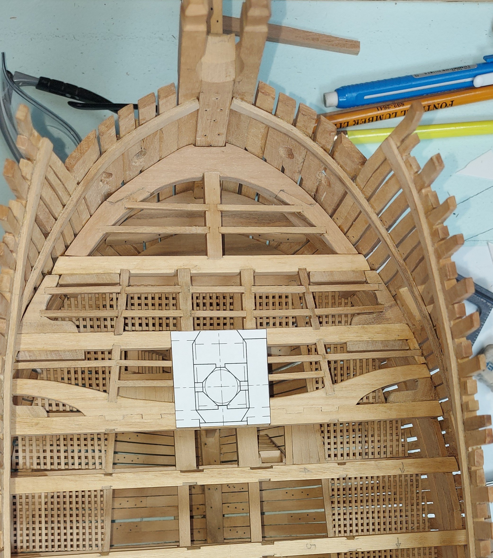
Here you can see the foremast partner template I've just made.
Hope to be cutting tomorrow as I already have the material sanded to thickness.

-
-
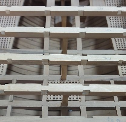
I am making and installing my ledgers, lodging and hanging knees beginning at the bow and working aft.
I may need to install one upper deck beam to secure my bowsprit step.
Then as I work further there will be riding bits, capstans, grating and coamings and mast partners.
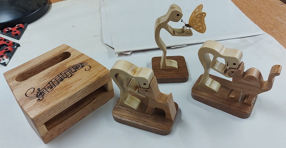
For something different to look at, I completed my gifts and I've decided to give them to my family members at our Thanksgiving dinner next month (3 weeks), not waiting for Christmas. The wood block is a cell phone amplifier for my son, the dog for my daughter, cat for my daughter-in-law and butterfly for my wife.
Hope the like them.
- mtaylor, dvm27, Thukydides and 9 others
-
12
-
Yes. After having been mentioned earlier above I did a search and that posting for the quarter deck and forecastle came up... but were there scuttles below those two, on the upper deck feeding to the capstan on the gun Deck?
- mtaylor and thibaultron
-
2
-
Thanks.
What a mess of lines! eh?
I'll try and contact them to see if they can provide a close photo of where the lines go but I have a strong suspicion they are just tied off.
- thibaultron, Thukydides and mtaylor
-
3
-
-
Ah, but there are in fact four capstans. Those below on the upper deck. At the time the upper and lower halves could be un-joined and operated separately.
Were there scuttles to pass ropes through the upper deck to the gun deck?
Could they hear the orders from above through to the gun deck?
Man handling the ropes might have been the easier option.
I am left wondering... even though I admit not using the capstans would work.
-
Thanks you.
I did read where Dr. PR wrote all of the falls would be handled by sailors.
My experience has been that no matter how many people you put on a tackle line, one or two are doing all the work, the rest a great actors.
My thought was possibly they would use the capstan as it would be easier work plus the pawls were a safety feature when lifting.
So, Wolfram zu Mondfeld in his book Historic Ship Models, top of pg 178, was misleading.
That buggers the plan formulating in my mind.
-
Thank so very, very much! (MSW rocks!)

I`ve spent the better part of two days trying to find any sort of detail on how it was done in the books in my library and the only one that came close was The Fully Framed Model, vol. 4. Several other books brushed up against the subject but left me as confused.
Your images above answer almost all questions.
I know the larger boats could weigh more than a ton and I imagine a few men on the tackle alone could raise the boat and swing it over the side without bothering with the capstan. What would be the preferred means... man handle by tackle alone or utilise the capstans with the tackle?
- AJohnson, thibaultron and mtaylor
-
3
-
You just taught me something.
Thank you!
- thibaultron and AJohnson
-
2
-
My build is British 3rd rate MOW in the 1790-1800 era.
I've just read that capstans were used for hauling anchors, installing yards and lifting/lowering boats.
My interest is in lifting and lowering boats.
I understand there were blocks used in the standing rigging and on the yards to lift/lower and swing in/out.
I assume the lift/lower lines ran to blocks on the upper deck (below the boat stowage beams) and were joined together into an extension single rope that wrapped around the capstan.
Has anyone ever read or seen anything to prove this?
Would the men manning the capstan be on the gun deck below that so as not to trip over the rope and be protected by the overhead deck from the boat being maneuvred overhead?
- thibaultron, mtaylor and Thukydides
-
3
-
Top timbers that thin will likely catch on something (shirt sleeve) and snap off
- Thukydides and mtaylor
-
2
-
-
I've noted that the columns seem to be referred to as pillars or stanchions, dependant on where you look.
The ones I installed below the Orlop deck were simple square sectioned.
These now being installed between the Orlop and Gun decks are square for the first and last 12" of their height and have the corners chamfered or bevelled in between.
The ones that will install on top of the Gun deck will be square sectioned for the first and last 12" and turned round in between with some steps creating a ball type shape at the top and bottom of this centre length.
I find that having measured the gap between decks is making the installation much quicker.
- GrandpaPhil, scrubbyj427, gjdale and 11 others
-
12
-
 2
2
-
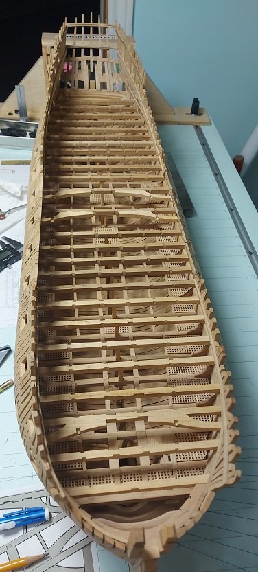
All main gun deck beams have been installed.
Working on making the support columns.
- druxey, mtaylor and mort stoll
-
3
-
Curious: What CAD program are you using to create your 3D model?
- mtaylor, tmj, Thukydides and 1 other
-
4
-
-
Pictures tell the story...
Arms installed. Now to get the other beams placed , then the columns then the ..... and the list goes on.
- marsalv, mort stoll, Seventynet and 14 others
-
12
-
5


HMS Bellerophon 1786 by AON – scale 1:64 – 74-gun 3rd Rate Man of War - Arrogant-Class
in - Build logs for subjects built 1751 - 1800
Posted
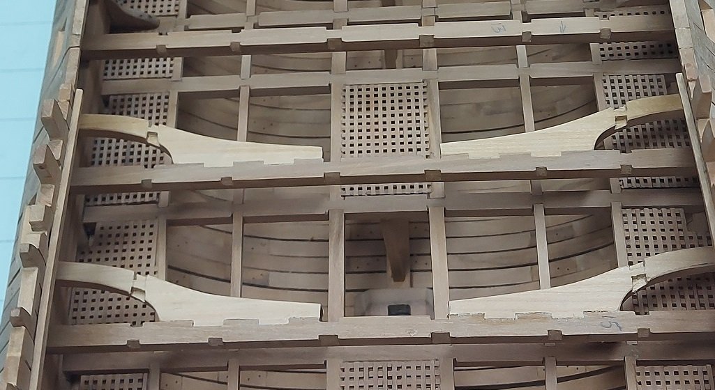
It seems I may have made a blunder with the foremast partner.
I may have added the two outer fore-aft running pieces and they shouldn't be there.
What I thought I saw on the drawing seems to actually be the carlings running between the deck beams.
I'll give my head a couple shakes and look again after lunch.
If I'm correct, they are easily removed.