


AON
-
Posts
2,792 -
Joined
-
Last visited
Content Type
Profiles
Forums
Gallery
Events
Posts posted by AON
-
-
-
Dave
I had a quick look at your sheet.
If I look at the data for the main mast in cell C13 that reads 48.94 feet the formula for that cell is =AG136
Cell AG136 is hidden.
If I scroll to where it should be (down to line 136 and across to row AG and unhide it I see all the calculation cells.
Cell AF103 hasn't populated the length of the deck properly.
It populated the beam so the formula should be (Beam + Deck Length)/2= main mast length but the cell is telling it to add (Beam + Beam)/2
-
I looked in The Fully Framed Model vol.4 by David Antscherl, The Anatomy of Nelson's Ships by C Nepean Longridge, The Young Sea Officer's Sheet Anchor by Darcy Lever, The Masting and Rigging of English Ships of War 1625-1860 by James Lee, and the back chapters of Rees's Naval Architecture.
Though difficult to tell by looking at some of the images, some straps/strops were definitely served. Like the Jeer and Quarter blocks. Others on smaller blocks on the yards don't seem to be served. Long strops seemed to be served whereas short strops on blocks forming a becket (eye) don't seem to be served.
At this moment it is all very confusing to me.
Possibly someone more experienced could offer guidance.
- Thukydides and AJohnson
-
 2
2
-
I will crack open some books this evening and get back to you.
-
I have to say I am amazed at your splicing at this scale!
You are serving the entire strop but the image does not depict the strop to be served.
Is that extra work for you, or did the image simple not show it?
- Glen McGuire, AJohnson and Thukydides
-
3
-
This sheet has cannon barrel lengths. Nothing to do with masts.
Try this spread sheet (attached) by Danny Vadas
It will take a moment to open so be patient.
At the upper left side of your screen may be a Security Warning saying some content has been disabled.
Pick Options, pick Enable the content, then pick OK.
enter your build scale in the box at the bottom and then pick Enter Data at the top.
scroll down to the year (1794) and across from 5th rate 40 guns enter your Beam (39.29) and Length (146.25) info.
At the top pick View Results
Now pick Masts and Tops- view results in Inches
Main mast 92.770 feet long and 2.354 feet diameter or 17.39" long and 0.44" diameter at 1:64 scale
-
-
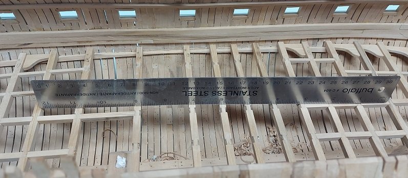
I have a CHARVOZ cutting base (made in Japan)
size 12" x 18"
Bigger is always better in this case.
I use it to cut my card stock templates for some of my ship model pieces... presently orlop deck knees, otherwise they would never fit properly.
Bought it about a thousand years ago when I was working as a junior draughtsman in an engineering office making small table top cardboard mockups of industrial quench tanks. In this age they would just make a 3D model and maybe even a 3D print!
Now, being retired, it has proven to be quite handy in the home shop
- mtaylor, thibaultron, Canute and 1 other
-
4
-
-
Rather then continue work on my standard knees, grating, decking or the last of the three stairways to the hold, I decided it was time to tackle the thing I've been avoiding... the hawse holes. The contract states they are 15" diameter, 15/64" at scale. I first double checked my heights then drilled my pilot holes at 5/64".
Next, with a new sharp bit, I drilled one inboard hawse hole very carefully and slowly with a backing board held on the inside.
Success! That was easy.
Drilled the outboard hole and it happened. She split and flew off.
That was unexpected.
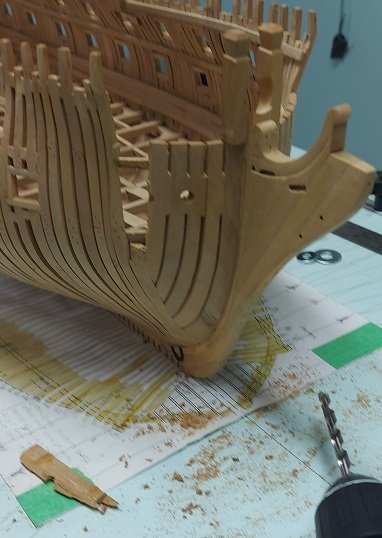
I setup the other side with clamps to help hold her together.
The outboard face of each of those holes have tear out chips in them!
So, I did the only thing left to do.
Glued the broken piece back on, clamped it up and left the room.
I won't be back working on her until Monday afternoon.
Good night world.
😉
- mtaylor, Beef Wellington, No Idea and 11 others
-
14
-
-
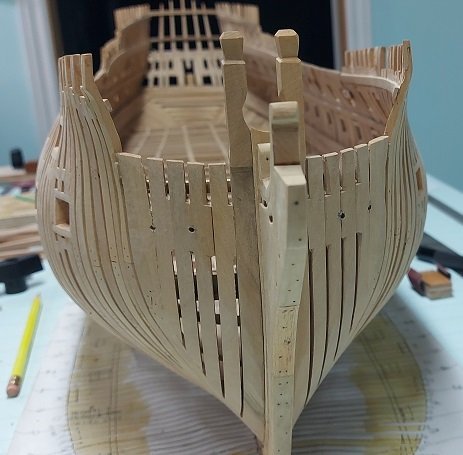
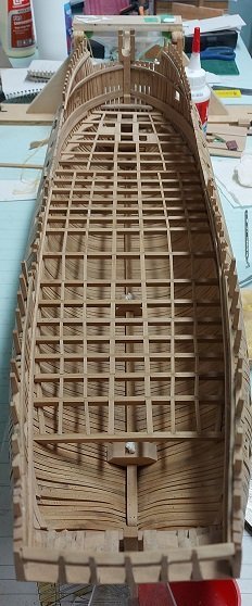
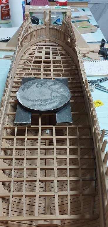
It has been an interesting week. Lots to report!
I installed all the beams and hadn't really notice "it" yet. Just in the zone happily moving along with things.
Started putting in the carlings and as I approached midships it became obvious.
What shall I do about it? Installing the orlop deck was meant to be a learning experience to prepare me for those above. The orlop deck was decidedly too deep for anything to be readily noticeable, so lets just move on.
Installed all the carlings and it was still there taunting me... "what?" you ask... the hump!!
The aft and fore are high and the deck does a gentle slope downwards towards the midships... or at least that what it looks like on the plans.
Mine has a noticeable rise or camel hump in it. I just won't look at it... but it is still there.
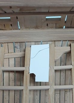
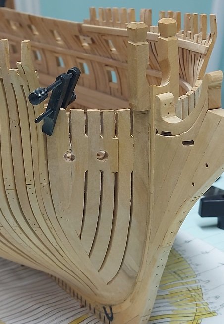
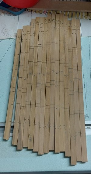
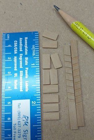
I decided to work on the ledgers and needed to make card templates as seen above. I installed them low, down on top of the deck clamp as their thickness plus the grating thickness equalled the beam height. This made sense to me. I could find no photos to suggest I was right.
I woke up this morning having made a determined decision in my sleep. I should have dealt with it, the hump, when I first noticed it. I hope this time I've finally learnt that lesson!
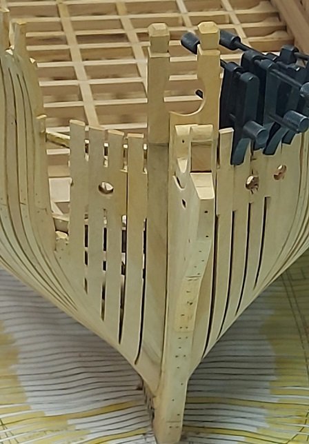
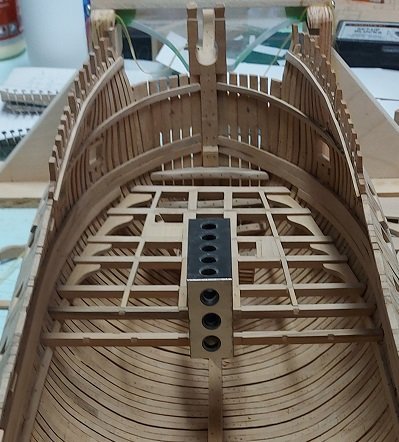
I measured the damage... about half a deck clamp in height. How it happened is of no importance, besides, I don't know the answer. Possibly my deck clamps slipped under the wooden clamps used to hold it in place when glued.
I determined which deck beams needed to come out. Cut the smaller carlings with my snips and used my flat nosed parallel pliers to persuade the larger ones to come out... almost like pulling teeth. Used the same pliers to remove the deck beams.
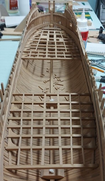
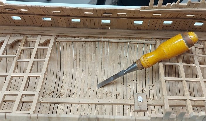
Marked the deck clamps and chiselled out the material to, at best, make the hump flat with the lowest points either side of it as seen above.
Reinstalled the beams and checked for flatness. Success! Glued and weighted them down until the glue sets up.
I feel much better about it now. When all is said and done I'll be thinking of how I corrected it, not how it is still hidden down there.
- mtaylor, GrandpaPhil, tadheus and 16 others
-
19
-
-
-
Everything looks good from a distance. Just ask my wife! 🤣
- mtaylor and mort stoll
-
2
-
slow going but I marked all the beams, removed them and am cutting and installing them one at a time to assure all the notches align properly.
slowly getting used to making shallower notches
getting used to it all
by the time I get to the gun deck I'll be... not quite a master at it but much better!
-
-
When cutting the ledges into individual pieces I first tried passing it through the blade with the notched side down.
That was a mistake as the blade tore the nubs off.
Then I turned it over and all was good.
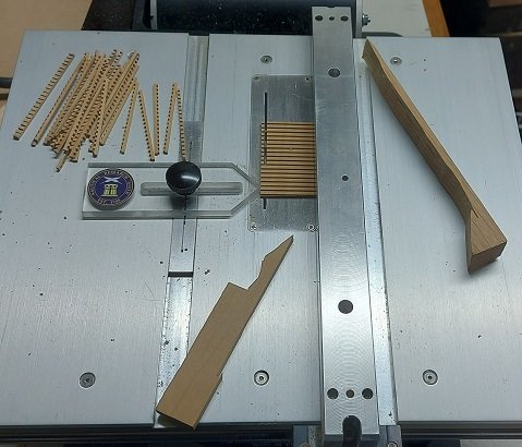
The battens were cut with the same setup with less concern for what side was up or down.
The assembly was done on the build jig.
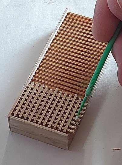
When the white PVA glue was dry the sides were sanded square and the top of the battens flush with the top of the ledge nubs.
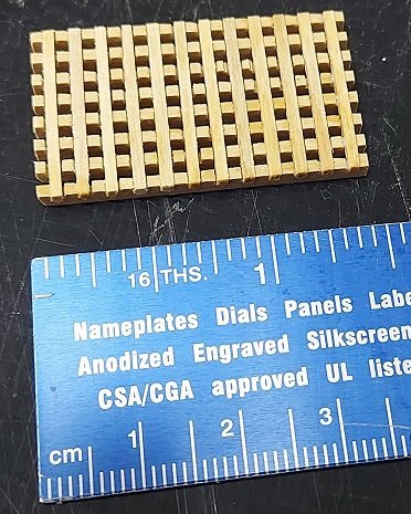
Here is the result of my very first grating ever.
Presently all the Orlop deck beams are temporarily glued in place to mark all the notch locations for carlings.
They will be removed to cut these notches on the bench as, try as I might, I could not manage to do them on the model.
It is a combination of the depth in the hull, the size of chisels I have and my skill level/confidence at this stage.
Possibly the higher decks might be a bit easier???
- Trussben, Mike Y, mort stoll and 12 others
-
15
-
I've been cutting and fitting beams. Fixing them in place temporarily with a tiny dab of glue so I can mark the notch alignments properly.
Not quite all done yet as I had to cut and sand more stock.
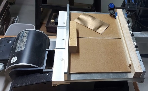
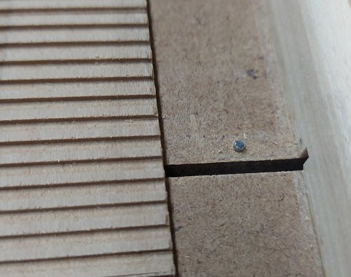
Meanwhile while I wait for glue to dry I've made a sled adaptor from scraps for my Byrnes table saw to cut the notches in my grating ledges.
The grating is made of ledges and battens.
for a 74 gun ship
- the fir ledges are 3" broad x 3.5" deep
- the oak battens are 3" broad x 3/4" deep
My saw blade is 0.57" wide which is 3.65" at 1:64 scale.... close enough!
I found a finishing nail at 0.55" diameter... perfect!
I used the nail (cut down to fit in the grove depth) as the pin on which the stock groove is incrementally stepped to cut the next groove.
I drilled a friction fit hole for the nail.
My grooves are slightly larger than the real ones at scale but we will keep that to ourselves.
The sled adaptor is clamped to the table saw sled so it doesn't shift.
I also found I needed to lift the stock clear and blow the sawdust away or it would lift the stock and I wouldn't get a full depth groove.
Now I need to slice up these into individual ledges then cut my battens to fit.
-
The plans show two stairs at the bow. Both enclosed on all sides with a door on one likely so no one falls down the hole.
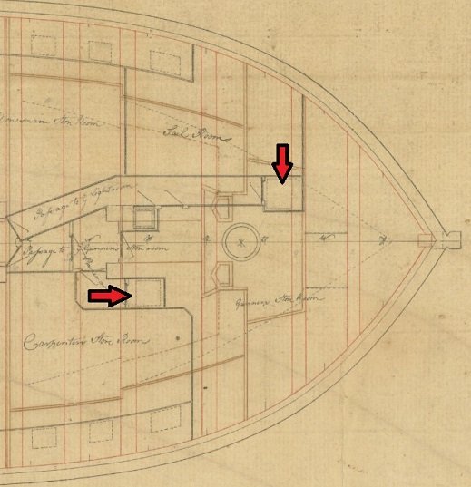
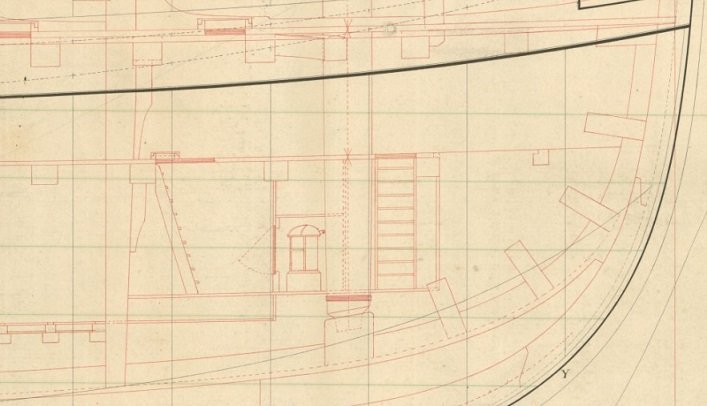
So I made a set of ladders per the above drawings. At 24" wide they are quite narrow.

They have been installed but I want to get some flush flooring and grating installed before the reveal.
As I did not install the platform below they hang midair, but no one is likely to notice that.
-
There is nothing I hate more then searching forever for information.
So to alleviate others from that predicament here is the info from Goodwin's "Sailing Man of War" on the Orlop deck construction with grating fitting along the outboard sides of the bulkhead and the planking being flush and removable.
First up is Page 59
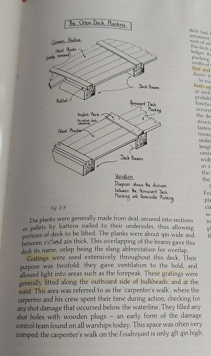
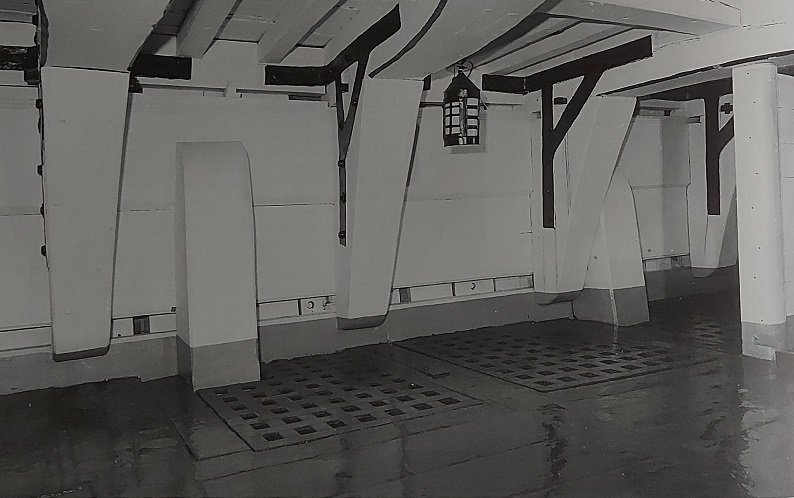
Second Pg 64 showing hMS Victory. Funny thing is that I watched the walking tour videos of HMS Victory on YouTube and they do not agree with continuous grating along the sides. I can only suppose this changed over time and refits.
The grating battens run fore and aft so there must be a support under the grating ledgers on the sides as depicted in the NRG Capstan Kit.
In this case a ledge block on the carling beam (or the carling beam is notched?) and the vertical lodging knee on the outboard side (likely notched).
Update: on closer inspection of the above it seems the carling is notched out to create a supporting ledge.
-
Possibly found one answer to one of my questions in post 1646 above.
In the book Sailing Man Of War by Goodwin pg. 58/59 for The Orlop Deck.
Gratings were generally fitted along the outboard side of the bulkheads and at the waist.
They also state much of the flooring was removable
So it may have been grating set into notches in the beams?
Wait... that's another question.
I'll keep looking
Update... turned a few pages and pg 64 shows a photo of the orlop deck of the Victory... grating inset into the beams to be flush at the top.
-
Masting and rigging the Clipper Ship and Ocean Carrier by Harold A. Underhill, pg72 fig. Plate 15, at the top of the Royal Mast shows a sheave for the Royal Tye at the top just under the truck and head (or pole). at the top of the Topgallant Mast is a sheave for the Topgallant Tye. At the top of the Topmast under the trestle trees and cross trees is a sheave for the Upper Topsail Tye.
- mtaylor and Keith Black
-
2
-
After seeing Druxey's image above I've decided, as a start, I will cut the ledge notches in situ.
I've been cut the carling notches and beams as a bevel. It seems I've been cutting them too deep. That might be what my problem is. If I cut them shallower it would be easier?
Druxey. Do you cut your's as a shallow pocket like the ledges?
Also, if there are no lodging knees for the first three and last four locations what supports that end of the outboard ledge beams?

Period Scale Model Masting and Rigging Tables
in Masting, rigging and sails
Posted · Edited by AON
Dave
You are going to chase your tail on this one.
These are rules of thumb they worked to in that age... but they weren't chiselled in stone if you get my drift.
Also, getting it dead nuts on seems really important right now, it took me about two years to get comfortable with working to a reduced scale and the "close enough" concept.
The difference between the two calculations at 1:64 scale is indistinguishable to look at and absolutely no one is going to take a vernier to you model but you.
If you can actually make your mast exactly to scale your better than me.
It is akin to a ship build contract stating what length and breadth the vessel was to be built to... and when done they wrote in the actual dimensions on the drawing.