


AON
-
Posts
2,792 -
Joined
-
Last visited
Content Type
Profiles
Forums
Gallery
Events
Posts posted by AON
-
-
Just coming through the other side of a rather unseasonably cold week.
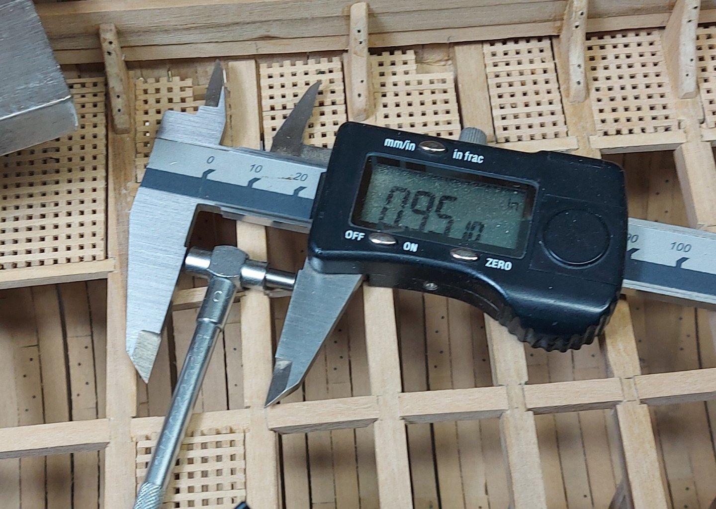
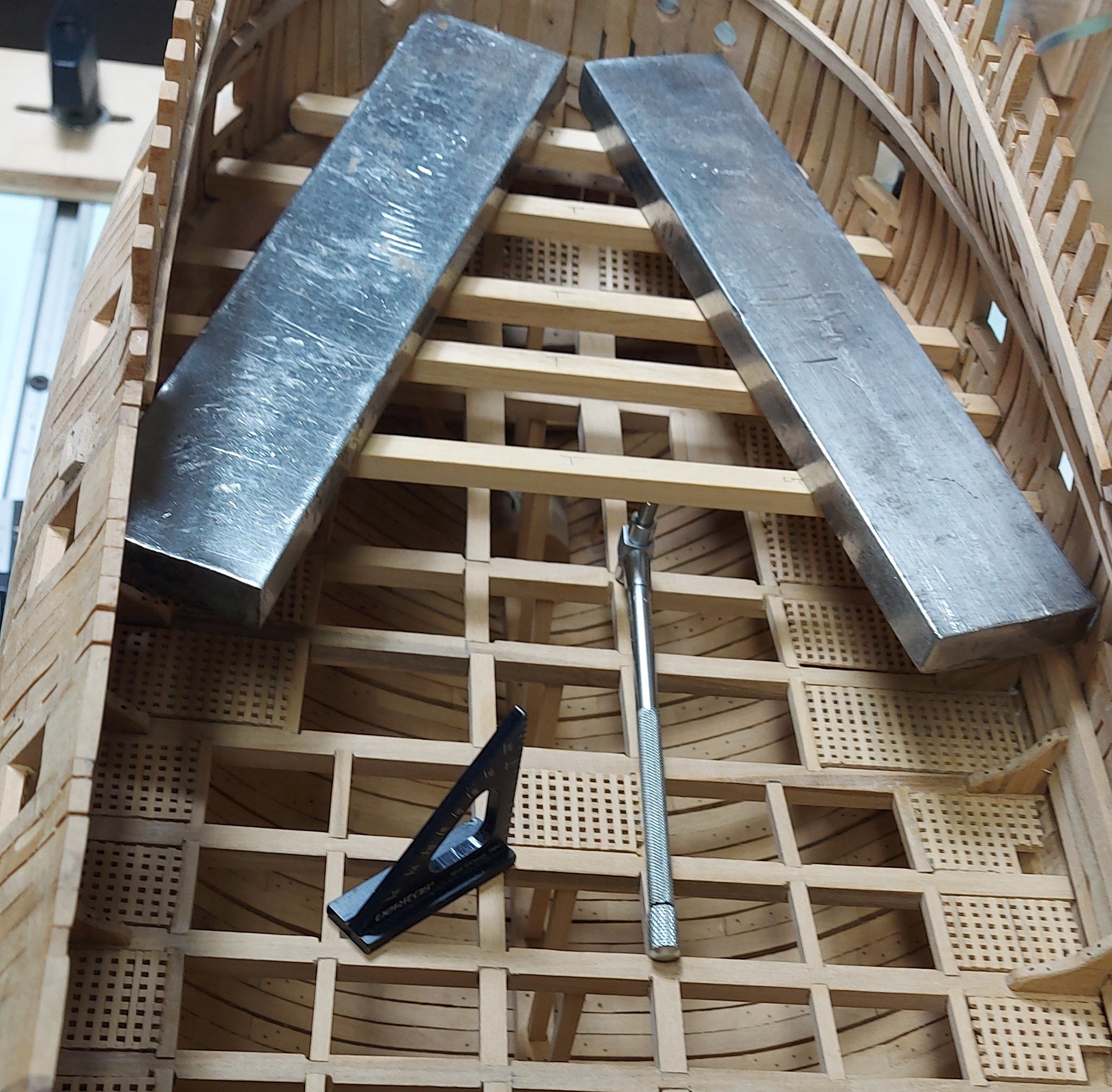
Below is my set up for cutting my notches.
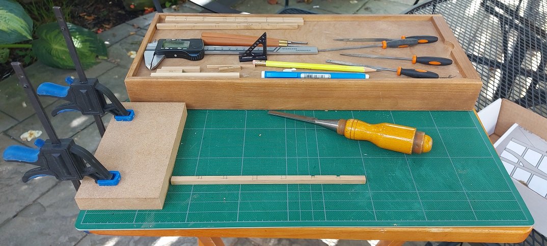
One short timber sample of each size carling. I marked the centerline and inside carling edges when originally mounted on the model. I didnt mark most outer edges.
Pencil and mini square to complete marking the locations. I use the sample pieces to locate the outer edge accurately and then draw my lines.
I use my vernier, set at 0.04"(2.5" at 1:64 scale), to scribe the depth into the top of the beam at each notch. If I overshoot my cut I will approach 3" depth which might be more accurate.
I use my 1/4" chisel to press in at the edge limits of the notch. My notches are mostly bevelled as opposed to proper square pockets of which I have some in the deck hook and beam arms.
I set the end of my beam against the dead stop (clamped block) so I do not need to hold the piece down by hand to keep it from sliding on the cutting matt. Slice in once from one side, turn it around, slice in the other side, use mini files to clean up, use mini chisels to re-sharpen the filed corners of the notch if they got rounded off.
Double check my notch width with the sample pieces.
Use my eraser to remove the pencil marks.
This works for me , and I find I am a bit steadier on this deck having had the orlop to practice on.
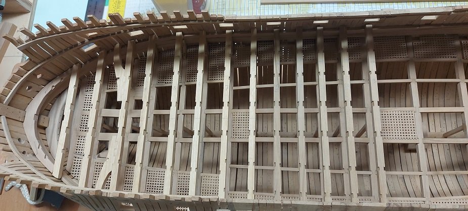
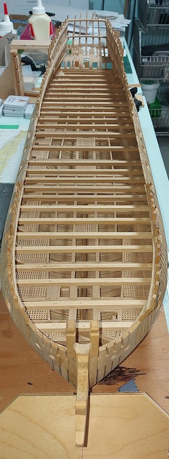
Below are the first group of beams installed.
Once they are all in I will fit and install the column posts, carlings, knees, ledgers and stairways.
-
-
It is difficult to get anything done on this build when the sun is out.
I have 10 of 26 beams notched.
I should have taken a photo of that process... will do the next time I set up outside on the patio.
Reassembled the three beams at the bow and dry fitted the arms so they could be notched for the carlings.
Progress is slow... but it is summer.
- druxey, KARAVOKIRIS, gjdale and 10 others
-
 13
13
-
Been a couple weeks since I posted.
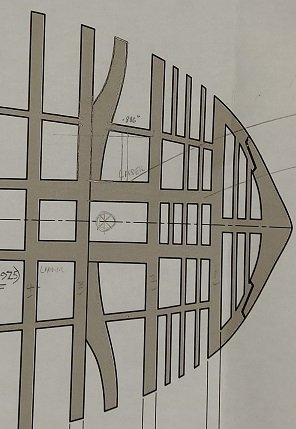
I had completed the deck hook in three pieces.
I marked all the carling locations and started removing the beams when I realized I hadn't made the three beam arms
Here my templates were laid over top.
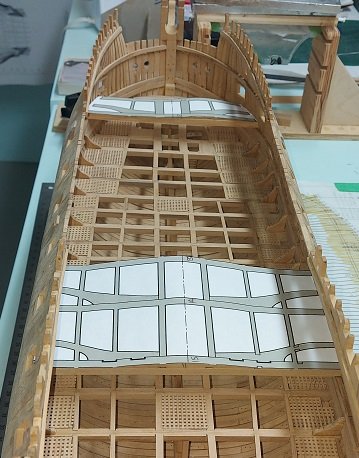
The beam arms (pairs still rubber cemented together) are made and all stored with the beams in a box.
I must now cut the notches ... cleanly this time
Oh, and I prepared stock for the carlings and ledges. I will also need to install the knees between the beams after they are re-installed.
I been preoccupied starting to make Christmas gifts in the shop.
Had to start early and have to be sneaky about it so no one accidentally sees their gift.

- bruce d, Thukydides, mort stoll and 11 others
-
14
-
Cat whiskers go to a fine point.
Paint brush hairs are cut blunt and thicker at the ends.
Which ever is appropriate for the job at hand.
-
One fellow working with CA on tiny parts used cat whiskers as an applicator for tiny deposits.
If you know someone with a house cat the whiskers fall off regularly and new ones grow in so if they spot them on the floor ask them to save you a few.
They are quite fine and stiff!
- Canute, Thukydides, Old Collingwood and 2 others
-
4
-
 1
1
-
I would never have thought to try that.
- Thukydides, Old Collingwood, mtaylor and 1 other
-
4
-
-
Yes, that is what I am now watching.
Interestingly.... I have a electric soldering gun with heat adjustment and a variety of tips, including a hot wire cutter!
- Old Collingwood, Canute, Ian_Grant and 2 others
-
5
-
... and again I am learning something new!
- Old Collingwood, Thukydides, Canute and 2 others
-
5
-
-
Obviously you meant CDO 🤪
- Canute, Thukydides, NavyShooter and 3 others
-
2
-
 4
4
-
Kevin
We have a member in the MSON club with one. They used it to make their copper tiles. Would you like me to dig up the name and send you his contact info?
Alan
- Thukydides and mtaylor
-
2
-
I had a few machinist tools I used regularly in a different life. Two dial verniers, a tee micrometer depth gauge set and the spring loaded telescoping (hole) gauge set.
Occassional I find a use for them in retirement.
- Thukydides, CiscoH, druxey and 1 other
-
4
-
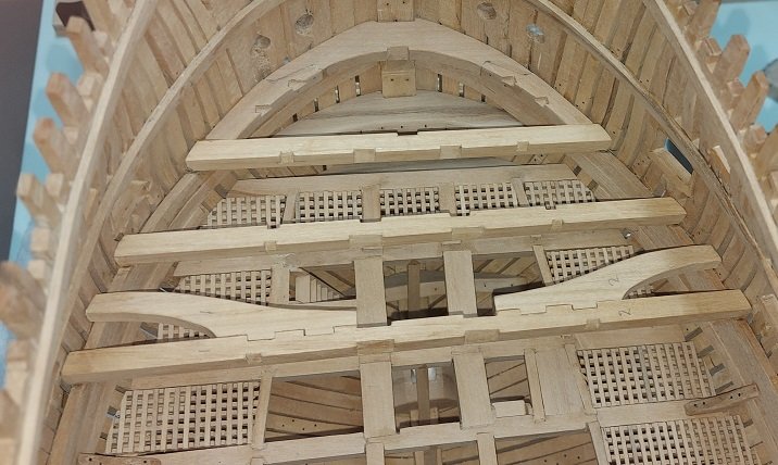
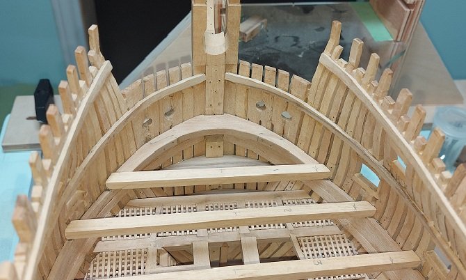
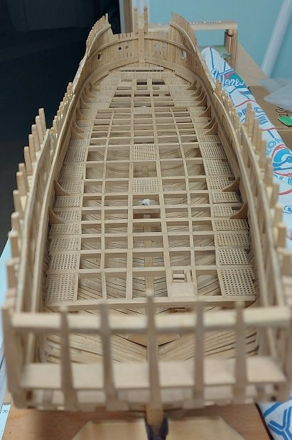
Gun deck beams fitted and tacked in place.
I used the small square to align the aft edge with the beam below so the gun deck hanging knee misses the standard orlop deck knee below.
(The first beam aligns with the one below. The second and third do not. Those after do again)
Telescoping gauge used to measure the gap between the orlop and gun deck beams for the height of the columns.
These beams are slightly fancier, square at the top and bottom and some turning in between.
Quite a bit to do before columns!

- PaddyO, druxey, fake johnbull and 5 others
-
8
-
Just recovering from another eye injection, 44th to date. This one was the best reaction/experience to my recollection and so I hope it means I might be getting better as opposed to the doctor has finally got enough experience 🤣
The last thing I did on my build was add the columns under the orlop deck beams (photo below). These were not fancy, simply 9" square at the base and slightly tapered upwards, but I didn't bother with the tapering detail. (I also started fitting the gun deck beams but no photos as yet)
I am now contemplating the purchase of a slightly used Soling 1 metre R/C sailboat as our club (Model Shipwrights of Niagara) has had a few members out sailing on the local recreational canal this summer and I've been out taking photos and videos of the events. I've got all my costs figured out, and my accountant is on board with the expense. I'll be test driving it on Tuesday morning.
If interested you can view a 4 minute video of the club's first r/c boating event here: https://vimeo.com/957260258?share=copy
- Thukydides, Erik W, albert and 7 others
-
10
-
Yes I did, but your method seems so much better than what I did. I hope to remember what you've recommended for the next time!
- mort stoll, PaddyO, mtaylor and 1 other
-
4
-
-
-
"Got up the nerve"
I know the feeling well.... and also the satisfaction and surprise when it actually works
 .
.
- mtaylor, Greg Davis and Canute
-
1
-
2
-
Standard knees installed yesterday. Glue cured today and I decided there is one last thing I want to do. I will drill and insert faux bolts in the knees to complete the look.
Here are a couple photos. Not much to look at.
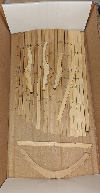
Today I cut my beam stock for the gun deck the beams at the bow and stern are slightly smaller but as no one will ever measure them and one cannot physically see the difference at this scale it is not worth the effort. I will square all beams to 16" (0.25"). They should be rounded to 5" (0.078") but that cannot be seen either so it is definitely not worth the effort. I shall try to do better with my joinery on this level.
I've very little Castello Boxwood left so I am now using Pau Marfim as that was what Exotic Woods in Burlington, Ontario, had in stock in 2" x 8" x 91". My 10 year old full size Canadian Tire "affordable" table saw died a few months ago so I bought a new one at RONA, an upgrade, and I like it very very much. I put the old one out on the boulevard and it was picked up by scavengers before the sun set.
Cut off a 20" length from the billet. Planed it flat on four sides then sliced it down into 0.3" squares on the Byrnes table saw. I'll sand them down to 1/4" square tomorrow on the Byrnes thickness sander.
And so we begin again.
-
Happy Canada Day everyone!
I haven't posted in a bit as there are many summer events and one special project keeping me occupied or distracted.
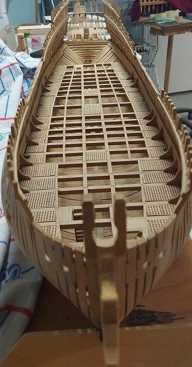
I did get all my gratings installed on the orlop deck and have been installing the standard knees on top of the beams... except the fore most three and aft most four and those adjacent the second futtock riders.
Thank goodness it is all deep in the hull as the assembly isn't as pretty as I'd like but it was good practice.
Possibly today or tomorrow I'll have them done. then I'll post a photo and start on the next deck.
- PaddyO, mtaylor, Thukydides and 1 other
-
4
-
-
hope the move goes smoothly and your back to building soon
- bruce d, mtaylor and Ryland Craze
-
2
-
1


HMS Bellerophon 1786 by AON – scale 1:64 – 74-gun 3rd Rate Man of War - Arrogant-Class
in - Build logs for subjects built 1751 - 1800
Posted
It's all wizardry!