


AON
-
Posts
2,773 -
Joined
-
Last visited
Content Type
Profiles
Forums
Gallery
Events
Posts posted by AON
-
-
-
-
-
Mike,
Short answer... nope!
(I have done a scratch build boat)
I fear I may not live long enough to complete the only ship I want to do, so, I dive into the deep end and if I should go "to the place of truth" before it is done I will have at least been working on it.
- mtdoramike and mtaylor
-
 2
2
-
-
Good morning Druxey
Because?
I imagined other more substantial reasons!

I have purposefully left minute gaps to help me with the breaks between pieces when making the templates
My breaks are between full scale 1/2" and 1" (depending on the location) which will not amount to anything in the build (0.016" max)
There are also other painful errors, for example there is a ripple in the outer surface of the stealer timbers at the stern below the lower transom pieces but the ripple is outwards and so will sand away if I should happen to be oversize a wee bit. I've tried and tried and it just gets worse so, I've thought it through and have my plan.
(I am also sometimes calling Waldo a stealer timber as I haven't found the proper term as yet)
There are also a few irregularities in the lower transom pieces that I can fix (blend) easier in the 2D drawing
I also left the radii out of the corners of the wing transom as my gut tells me I should gentle do this by eye sanding the pieces
I've had to make decisions along the way, and will live and learn by them.
Lord knows there is likely something I haven't noticed... seeing the forest for the trees kind of thing.
Alan
- druxey, mtaylor and Seventynet
-
3
-
Good morning Mike
Yes it has been a long time, no one knows it better than me
I had a false start building a year ago but approached it wrong and I didn't like what I had done
I have had at least three starts at modelling, this last being a switch from SolidWorks to Inventor.
Besides having caught many errors, learned many things about the ship, I also learned about 3D modelling which has been quite valuable for work.
Although I do not draw at work anymore (I do not model) my co-workers do, and the mystery surrounding the process is gone.I expect it will take me a few weeks to complete my templates and have two sets printed... then I start.
It takes time to clear your head and then the mistakes leap off the screen/sheet and they can be addressedI've been going slower this last attempt at modeling and will be taking my time with the build.
This will be my first scratch build "ship" and I am learning so much.... including patience; not something that comes naturally to me
It is also the first time I've made my own templates
Many firsts happening here
It is as much about the journey as it will be the completion.
Alan
-
-
-
-
advice?
We are always our own worse critics
and this is as it should be
I like what you've done and anxiously wait to see how the small changes make huge differences.
My first thought with the above photos was "OMG she's tall"
BZ
Alan
-
-
Now you are being modest.
As a former hunter I appreciate the ergonomic design of a perfect grip and shoulder rest, balance of the stock, length, etc...
Then there is the fit and finish of a real wooden stock (not that plastic crap they sell now) that brings a smile to my face.
-
Cut away the parts that didn't look like a rifle ! ? !

You make it sound easy.

it can't be so simple..... can it ?

- mtaylor, CaptainSteve, avsjerome2003 and 1 other
-
4
-
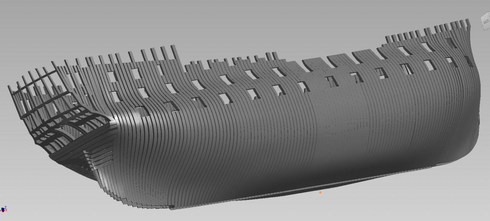
Fast approaching two years and little to show.
I am about where I was in my last model when my computer died and I lost my privilege to using SolidWorks.
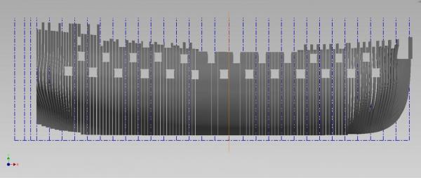
I've completed (for the most part) up to frame 28. Need to add the Gunports.
The last couple quarterdeck gunports are drawn narrower than actual as the frames are bent and if I cut out the full gunport I'd loose the frame cutting template detail I need.
About to complete the stern.
Below is a snip of my progress and what is left to do!

Being an old draughtsman I admit to not being able to see my own mistakes and so relied on my working associates to check my work after I had thought I'd thoroughly reviewed it. I miss my checkers but alas they wouldn't know what to look for in these models and drawings. The further away from the Dead Flat I get the more my errors pop up. Caught most (I believe) but will have to clear my head and give it a few final reviews when I am done.
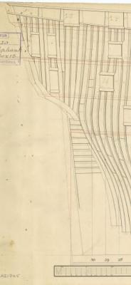
I have not drawn in the shifting, bent and very special frames shapes as I will be working very closely with a clean print of the original framing draught to pick up those details. My drawings are to get the basic molded shapes for cutting.
Will post again when I am done... or I stumble again.
BTW... my "Waldo" frames proper name still eludes me and I continue to look.
-
-
Sometimes we are just to close and involved to see "outside the box"... that is where an extra set of eyes come in handy.
I like the 'see through' option of the plexiglas
I also have a set of machinist's squares and find them very handy
So I am torn between Greg's suggestion and what you are doing!
-
-
-
-
Thank you for the very good suggestion Jagger!
It was suggested this would take some research to find out.
I'm guessing it was not that common.
I have a small library that I will look through once more... and of course there is the inter-web which I will delve into further but I have a feeling you may be correct as it may have just been a "toptimber filler piece" as opposed to that sneaky little so and so.
For the present mine will be referred to affectionately
as Waldo.Regarding your comment on the choice of build... there are moments I feel I may have bitten off more than I can chew but I have nothing but time and I can be very patient but certainly never quit. I am hoping it will be more fun than it seems. It will definitely be a worthy challenge.... and ah loves a challenge!
Alan
-
-
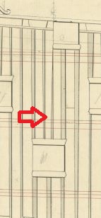
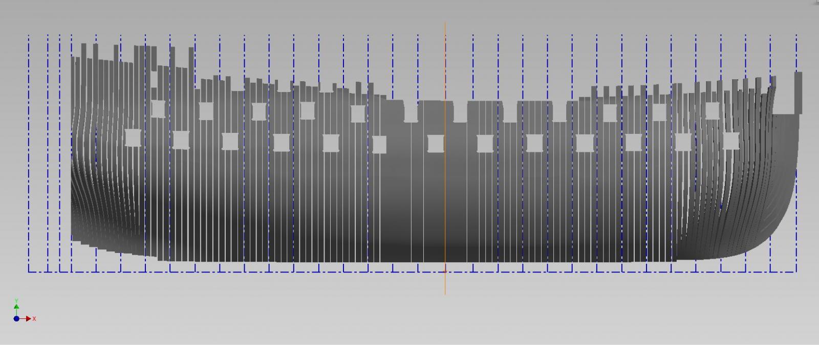
Can someone tell me the proper name for any extra partial top timber frame?
I was into a rhythm drawing my frames and suddenly noticed something was wrong.
After about 20 minutes I suddenly saw it tuck in between two frames above a gun port.
(see the attached image below)
Of course I had some choice names for it at the time, but now that I've had time to... reflect... I probably should be calling it something else.
Thanks in advance for your help with this.
Alan
-
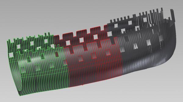
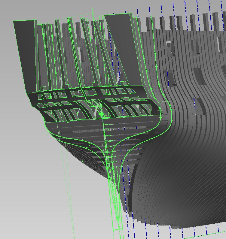
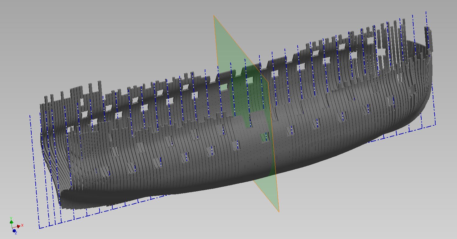
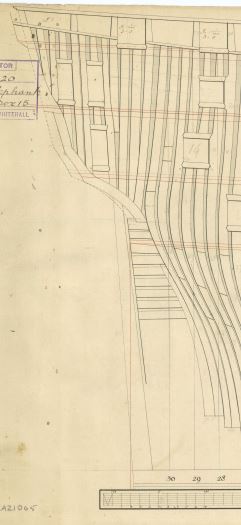
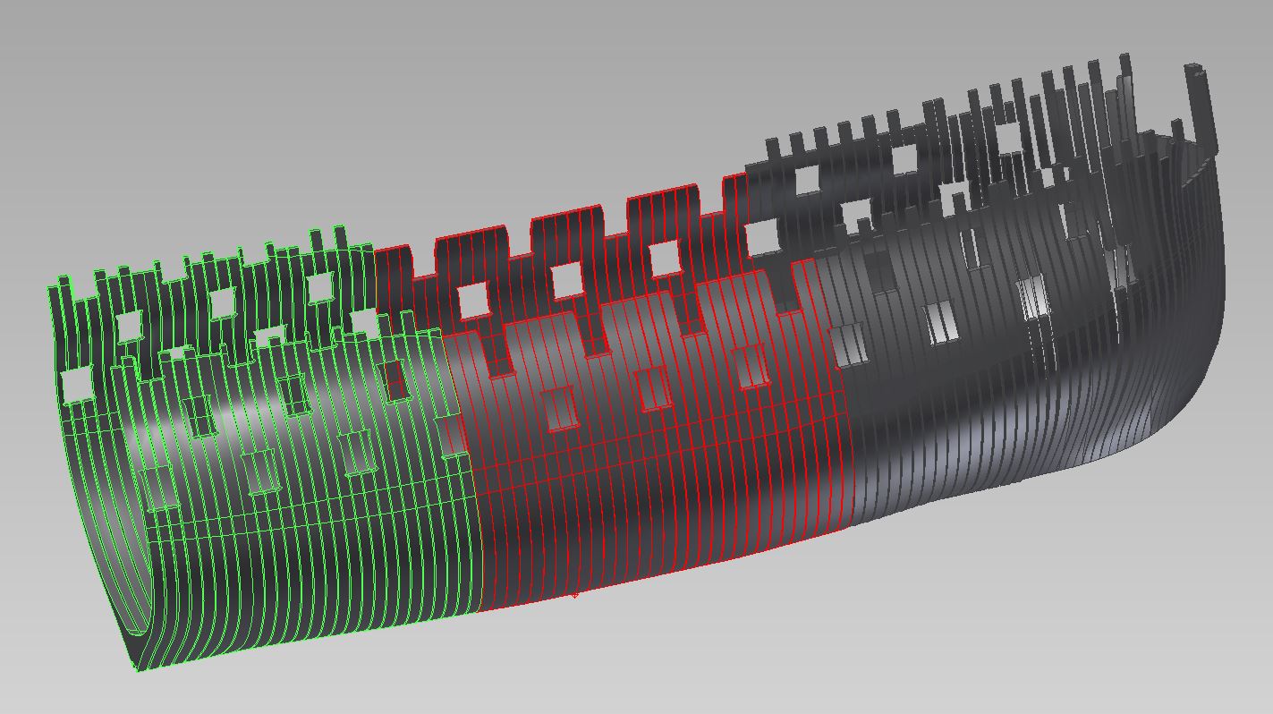
some progress aft (the green highlighted portion from station 2 to 16)
it is slow going but I may possibly have the framing templates completed before Christmas
then I try my hand at building again
- avsjerome2003, tadheus, mtaylor and 5 others
-
8


HMS Naiad 1797 by GDM67 - 1:60 - using Ed Tosti Books
in - Build logs for subjects built 1751 - 1800
Posted
love the photos, details, locking cams for chiseling/shaping the deadwood, etc...