Jump to content

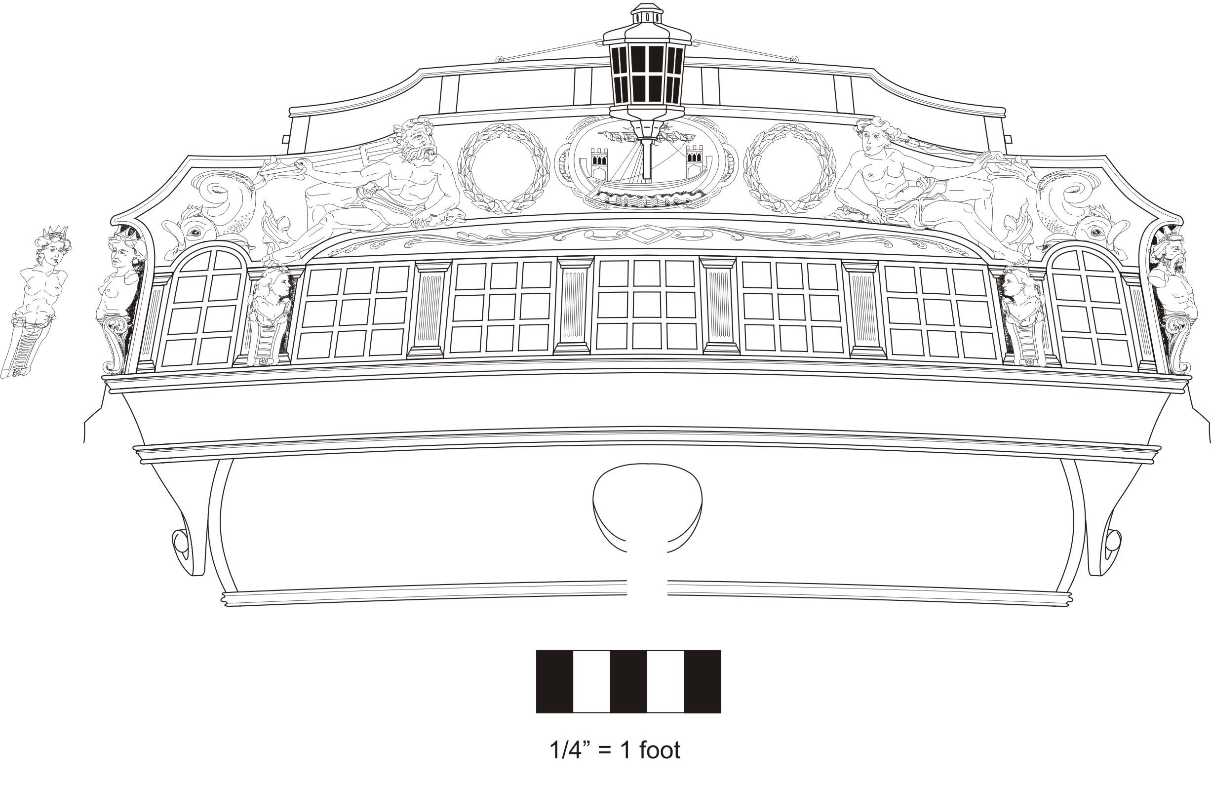
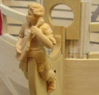
HMS Winchelsea 1764 by Thistle17 - 1:48


Recommended Posts

Joe, im Not sure what kind of glue you are using but I found the mistakes I made early on were easy to correct by using some denatured alcohol to soften the PVA and move/adjust pieces, in fact I think I even encountered a similar problem on my framing as you are experiencing, I just softened the glue and made adjustments. Rebuild your transom frames and glue back into the slots, set your angles with a jig and let set. This is a recoverable problem. 

Current Builds: HMS Winchelsea 1764 1:48 - 5th rate 32 gun frigate (on hold for now)


                         HMS Portland 1770 Prototype 1:48 - 4th rate 50 gun ship


Link to comment
Share on other sites

I managed to remove the sawn off frames and preserve the openings in the existing bulkheads. Of course there is residual PVA in the joints which will prevent good bonding of the new frames. I will attempt some remedy without opening up those frame slots. I had mentioned that I had two unused intermediate elements that were meant for the first go around. They are shown dry fit between #28 and #27 bulkheads. While they do not add much as fillers for strength they certainly will give some much needed unspoiled glue surface for the frames.


I am milling the boxwood for the frames and will be cutting them out shortly.


The saw in the foreground is the one I referenced earlier. It is such a great tool!


Joe

P1010426.JPG

Link to comment
Share on other sites

As I was preparing to build anew all the elements of the transom it struck me that I might try to salvage the transom that I had sawn off on my last attempt at assembly.


Since my transom angle was the driver for the removal it seemed to be a waste to just abandon it without trying a repair. I first trued up the cutoff ends of the port and starbaord C/D frames. Then I mortised into the cleaned up ends a deep enough mortise to give a tenon a substantial seat but not too deep as to protrude aft. Having saved scrap cedar from the kit I glued up "extenders of the same material thickness and let in the registration socket in each. One "extender" was cut to length (including the tenon length) for the starboard side. It was glued up using the cutout template for the element alignment. Since it had broken away from the transom full assembly it was easy to machine. The fuller assemblage was a bit awakward but it did fit my mill vice with some creative clamping. The port side extender will be cut to length and milled in a similar manner.


The mid transom frames would be more difficult to repair with them in an assembled manner so they will be treated differently. Since they require simple extenders I will "sister planks" of appropriate dimension to A and B frame ends. Having done so I will open up the respective bulkhead slots and reinstall the repaired  transom. And this time I will use the template guide I fashioned.


Hopefully I will be back in business soon.


Joe 

P1010428.JPG

Link to comment
Share on other sites

After preparing all the sistering planks to facilitate use of the existing transom framework I had second thoughts about this method of repair. Knowing that a poorly fit and aligned transom implied problems, possibly unrecoverable, when it came time to include the quarter galleys I scrapped the idea.


Instead, using the kit blanks for the intermediate frames I made new ones of boxwood. As stated I never throw away the "blanks" for just such a reason. I remade frame pairs for 'A' and 'B' elements. They were rough cut on my scroll saw, sanded on my disc and drum sanders to the traced lines and they were hand tuned with files and chisels. Finally they were ganged together and fined tuned further for conformity. By the time I finished I had yet more respect for the accuracy and repeatability of laser machining. 


I was able to repair the 'C' and 'D' pairs as stated earlier so with the spare filler parts included in the Chapter 1 ensemble I will start again to assemble the transom using selected techniques developed by those wiser than me.


Joe

P1010430.JPG

Edited by Thistle17
Link to comment
Share on other sites

  • 3 weeks later...

After some 20 days of on and off focus on this build I finally believe I have a worthy transom construction that will carry me through. The first photo shows the transom sub assembly (sans the lower sills) dry fitted onto the frames. If you have been following along my path to this point you are aware it has been a circuitous and not without folly journey. Fundamentally I just did not appreciate the criticality of the transom positioning in relation to the quarter galleys. So anyone approaching this area should be fore warned.


Having said that and for what it may be worth to others I would like to share my methodology. I would not say it is the definitive way of doing things for there are a number of ways within the build blogs that worked but for me it replaced the awkwardness of paper patterns especially when removing and replacing the assembly.


In stepwise fashion here is how I approached the construction:

1. After making the new frame members and repairing the P and S outer ones I repositioned them in the registration slots on bulkheads #27 through #29. My slots were a bit sloppy from my first try at building the transom so some shims were needed to hold them in place.

2. I then took the transom laser cut outer 'skin' shown in the second photo and clamped it to the outside of the frames. It was positioned so that the relief around windows was equal. The "fit" templates (1 thrugh 5) were then placed in between the clamped frames and the whole was adjusted accordingly to ensure that this piece was placed vertically (aligned at the bottom to the topside of the upper edge of the counter) and again symetrically around each window opening.

3. Lines were traced down the inside of the transom piece where the frames should align. See the markings on the inside of the transom piece. You will also note a center line on the transom piece.

4. Starting with the inner 2 frames the filler piece was sanded to fit the exact opening. It was then glued in place to both 'A' frames. It too was marked with a center line.

5. This assembly was removed from the model and the aft side was rough sanded to nearly its final thickness.

6. This sub assembly was returned to the model and once again aligned with the transom piece via the premarked center lines.

7. The next transom filler piece was edge sanded (with the appropriate taper) using the guide on sheet 1 of the plans and trial fitting on the model such that the port hole concentricity was achieved. This is a bit tricky but doable in carefully repeated steps. The registration guide supplied (i.e. #2) was used to ensure that the sizing was proper. It was then returned to the model and glued to frame 'A' only.

8. Once the glue had securely bonded (I take extra clamp time when edge grain is glued to face grain) I then sanded this added filler off the model to near flatness to its frame. I then reclamped the transom filler to the frames ensuring alignment and clamped the 'B' frame to this new sub assembly to check for edge trueness, port hole alignment etc. If satisfied I glued frame 'B' to the sub assembly.

9. This same process was used for the port side filler of the same type.

10. Iteritively, this process was repeated for the remaining frames and fillers.

11. I must repeat that all along the way I used the spacer registration pieces 1 through 5 repeatedly while fitting and during assembly. And as importantly I used the angle template made from the drawing to ensure that the final assembly would have the correct tilt from vertical.

12. Lastly if one measures off the drawing where the inside of transom piece 'C' must tie into bulkhead #28 with the horizontal member that becomes the header for the quarter galley passage way you will find that it has to be 61mm across its top. Before final gluing that should be checked P and S.


Joe


Just an editorial comment: Chuck must have had me in mind when he made duplicates of all the transom filler pieces. I used and went through them only having to make the outer ones from scrap on the originally supplied parts blank.

transom.tk2.JPG

transom prtsntools.JPG

Edited by Thistle17
Link to comment
Share on other sites

It’s good you took the time to get it right. Everything done right now pays off later in the build. 
 

Be sure to follow the plans getting the lower counter and stern end of the wales right. 
 

Your patience and attention to detail are serving you well. Nice work!

Regards,

Glenn


Current Build: HMS Winchelsea
Completed Builds: HM Flirt (paused) HM Cutter CheerfulLady NelsonAmati HMS Vanguard,  
HMS Pegasus, Fair American, HM Granado, HM Pickle, AVS, Pride of Baltimore, Bluenose

Link to comment
Share on other sites

And thank you Glenn for the encouragement and alert. I have been looking ahead and have anticipated the need in this area. I am plodding ahead with the gun port lower sills as I write this. Indeed boring and annoying as the placement of those members is such a pain. I have found that the only good way to fit those members is to use my Byrnes sander and carefully tune them to fit. It is surprising that with all the time I took with the bulkhead positioning that I find when using Chucks measurement of the members right at the strong back by the time I get out to their extremities they are quite different! I have had to clamp them in place to hold their position in most cases. I will also add the members in the areas where the gun ports are absent to make the assembly more rigid.


One amusing thing I found was that my "clever" method to hold the fragile uprights in place with spot glued battens had to be removed to make the sill and filler install work as I had no lateral movement capability.. Seemed like a good idea at the time!


I do have one question that maybe folks can help me with though. I have yet to run across an indication of just how thin the inside of the uprights of each bulkhead should be sanded after I finish the hull planking. Is there a measurement stated somewhere?


Joe

Link to comment
Share on other sites

1 hour ago, Thistle17 said:

use my Byrnes sander and carefully tune them to fit.

I did the same thing, it’s a great tool.


1 hour ago, Thistle17 said:

how thin the inside of the uprights of each bulkhead

It’s in the monograph, 3/16ths, the width of the cap rail. The pattern can be printed out on the chapter 10 monograph. 

Regards,

Glenn


Current Build: HMS Winchelsea
Completed Builds: HM Flirt (paused) HM Cutter CheerfulLady NelsonAmati HMS Vanguard,  
HMS Pegasus, Fair American, HM Granado, HM Pickle, AVS, Pride of Baltimore, Bluenose

Link to comment
Share on other sites

  • 1 month later...
  • 2 months later...

Glenn I wish I were at the planking stage. It has been one interruption after another mostly family needs. I did finish and deliver a display table to my daughter and am wrapping up a portable stand for my Sherline lathe ( I will debut it a bit later). As I work in our study/computer area I have to constantly work to keep the area clean. In addition Winchelsea is so big I have had to come up with a temporary" work bench extension". The lathe stand will help solve that problem as it can support the model when not serving the lathe.


So Winchelsea has suffered. As witnessed by this post where I am asking for a little guidance. I have been fairing the stern area after "plinking away" on the gun port framing. I have used a number of MSW builder references including Chuck's postings for stern faiting. To me it seems a bit subjective as to how to achieve the desired end point.The attached picture (with mark ups) shows my progress on this critical area. I have rough formed one of the fillers that will "land" the planking for the port side. Using fairing strips it appears close to the correct taper torward the stern but still needs tapering towards the port side. I have crudely marked that area in green.


Secondly the stern post area still appears to need contouring all the way down (up) to the filler. This suggests that frames 29, 28 and 27 need much more sanding to an even more wine glass contour.  Am I correct here?


And lastly it appears the bottom side of frames C and D need little to no tapering towards the stern save for the side. That appears to need some build back. Again am I correct?


Joe

strn.win.mrkup.jl.png

Edited by Thistle17
Link to comment
Share on other sites

Already I forget, but I explained what I could in my log. Seems like the counter is planked first to give you the place to end the planks. It is a challenge for sure. Definitely yes on the red mark or something close to it. 

Regards,

Glenn


Current Build: HMS Winchelsea
Completed Builds: HM Flirt (paused) HM Cutter CheerfulLady NelsonAmati HMS Vanguard,  
HMS Pegasus, Fair American, HM Granado, HM Pickle, AVS, Pride of Baltimore, Bluenose

Link to comment
Share on other sites

Thanks for the coaching Glenn. I have hesitated on the counter planking but will do so now.Your postings is one I follow closely. Your progress is amazing.  I have to develop some rythm for my build. The stop, start method I seem to be in just makes the build more arduous.

I am not sure I mentioned it before but I worked in Dallas for a year back in 1973 - 1974 on Mockingbird Lane at the corner of I35. Lived in Denton. That was a 32 mile trek to and fro on I35. It was crazy then has to be a white knuckle drive now I would imagine.

Joe 

Link to comment
Share on other sites

I am taking your advice Glenn and began the process of planking the lower counter. As I approached strake #5, in a dry fit mode,  I encountered a bit of interference with the stern post. I have checked and checked every aspect of the stern framing and the remade frames A and B. They are pretty much on. Rather than fight this I have decided to premark the stern post cutout at this stage and "prep" this area for removal while on the bench. I Have also included the relief in stake #5 to get around the interference problem. I will allow some tune up real estate once that stage is reached on the model.


It isn't that long ago that I remember my difficulty with Cheerful's stern post relief so I have to assume in the long run I will be more satisfied with the outcome.


Joe

win.cntr.prep.JPG

Link to comment
Share on other sites

On 1/6/2023 at 7:40 AM, Thistle17 said:

has to be a white knuckle drive now

Not at all, that’s because you’d never get above about 30mph the whole way😂

Regards,

Glenn


Current Build: HMS Winchelsea
Completed Builds: HM Flirt (paused) HM Cutter CheerfulLady NelsonAmati HMS Vanguard,  
HMS Pegasus, Fair American, HM Granado, HM Pickle, AVS, Pride of Baltimore, Bluenose

Link to comment
Share on other sites

7 hours ago, Thistle17 said:

I encountered a bit of interference with the stern post.

Likely not a big deal but carefully check the start point for the top of plank 1. The transition from upper and lower counter is important and not as obvious as you’d think. Try a little. dry-fitting there. We all know our models won’t be fit like Chuck’s. I made lots of little adjustments here and there. The planking transition from sternpost to counter took me multiple tries and a couple of weeks to sort out. But it does sort out…

Regards,

Glenn


Current Build: HMS Winchelsea
Completed Builds: HM Flirt (paused) HM Cutter CheerfulLady NelsonAmati HMS Vanguard,  
HMS Pegasus, Fair American, HM Granado, HM Pickle, AVS, Pride of Baltimore, Bluenose

Link to comment
Share on other sites

Yes Glenn I suspected this and have dry fitted the placement and even marked the placement on the aft side of the frames at least 3 times. The lower/upper junction intersection is indeed a caution. Moldings can't hide everything. Thank you.

I was on the phone with Rustyj yestrerday and he too was quite helpful. I value everyone's advice.!!!! Where else but here could there be such a helpful community!!!!!!

Joe

Edited by Thistle17
Link to comment
Share on other sites

I heeded your warning regarding the upper/lowercounter positioning Glenn. Sure enough if I had proceeded with the placement of just the lower counter as I thought correct I would have been off the mark for the upper counter. I have repositioned and dry fitted the lower counter and also dry fitted the transom "skin". I have marked the correct positions and now it is a matter of fine tuning so the upper counter will dock where it is required. Thank you again you are saving me some pain and agony!

Joe

win.frz.jl.JPG

Link to comment
Share on other sites

Glad i was helpful. The trial fit of the friezes really helps visualize it all. 
 

Nice work, you’re on your way. 

Regards,

Glenn


Current Build: HMS Winchelsea
Completed Builds: HM Flirt (paused) HM Cutter CheerfulLady NelsonAmati HMS Vanguard,  
HMS Pegasus, Fair American, HM Granado, HM Pickle, AVS, Pride of Baltimore, Bluenose

Link to comment
Share on other sites

The purpose of this post is more of a personal nature than news worthy to others. With my committment to the Mark I PBR completed I can be more focused on this project. Today I milled the wales first layer planking out of AYC that I happened to have. After confering with the "master' it was suggested I use other than the stock supplied as future need may arise.


The wales have been carefully aligned (even checking the P/S height to ensure symmetry after slight adjustment). So now I am ready to start and this post is a marker to see how long this is going to take.

Joe

P1010492.JPG

Link to comment
Share on other sites

Great to see you at the planking point Joe. 

Rusty

"So Long For Now" B) 


Current Builds: Speedwell


Completed Build Logs:  HMS Winchelsea 1/48   Duchess of Kingston USF Confederacy , US Brig Syren , Triton Cross Section , Bomb Vessel Cross SectionCutter CheerfulQueen Anne Barge, Medway Longboat


Completed Build Gallery: Brig Syren , 1870 Mississippi Riverboat , 1949 Chris-Craft 19' Runabout


Link to comment
Share on other sites

  • 2 weeks later...

I learn so much from other, reading posts and confering with those that have advanced before me. Truly a gift!


After completing the wales first layer on both sides, I was anxious to try my hand at the second layer. Stuntflyer coached me through the process and I must admit it is quite straight forward. One justhas  to progress slowly and deliberately. Mike's "stops" to align the black strake at the top is such a simple but effective measure. I colored the top edge with a Winsor Newton Pro Marker, XB Black, rather than paint it with acrylic so as not to have paint build up on the back side. Since the strake from the bow was too short I 'buried a butt joint under the anchor lining and then continued on to follow the pattern.


That void in the first layer wales at 'G' I caught too late. It is such a smooth run that breaking the joint and reclamping I anticipate will foul me up with the lower planking. So I made the wales strakes just a tad wider than the 7/32" so the second layer will over lap by just a tad.


Joe

P1010502.JPG

Edited by Thistle17
Link to comment
Share on other sites

It looks good.  BUT its odd to me why you would glue the black strake on before you glue the second layer of wales on.  And the 1st layer above the black strake.   Was there a reason why you decided to do it that way?  When you sand the layer above the black strake it may very well screw up the black strake.  Just me thinking out loud.  But I suggest to stick with the order mentioned in the monograph chapters.  You may run into issues later on.   

Link to comment
Share on other sites

I think the black strake isn't black?  As Chuck, notes the handy thing about putting in on after the above the wales planking and after the second layer of wales is you get a nice clean paint line on the top of the wales with the not painted black strake above it.  Maybe it's nomenclature and what your showing is actually the top plank of the wales?

Regards,

Glenn


Current Build: HMS Winchelsea
Completed Builds: HM Flirt (paused) HM Cutter CheerfulLady NelsonAmati HMS Vanguard,  
HMS Pegasus, Fair American, HM Granado, HM Pickle, AVS, Pride of Baltimore, Bluenose

Link to comment
Share on other sites

Maybe it is time for me to call a 'time out" on myself. I had quite a time milling my 1/64, 2nd layer wales stock until I took the time to set up the saw with a new blade. modify my cut off jig to work on my larger table top. Then and only then was I able to fine tune the strakes to the desired thickness. To make the story a tad longer I found I was eating up the cut strakes a bit getting the butt placement so I was hesitant moving

the setup until I understood the consumption. Hence the start of the top black strake. I now realize that I will need to sand the black strakes a bit so indeed it was only a good idea to do only the edges with the pro Marker. I will either rip it off or finesse that one in place and return to the regimine layed out.


Joe


Edited by Thistle17
Link to comment
Share on other sites

Hi Joe. I'll talk to you tomorrow about this. 

Rusty

"So Long For Now" B) 


Current Builds: Speedwell


Completed Build Logs:  HMS Winchelsea 1/48   Duchess of Kingston USF Confederacy , US Brig Syren , Triton Cross Section , Bomb Vessel Cross SectionCutter CheerfulQueen Anne Barge, Medway Longboat


Completed Build Gallery: Brig Syren , 1870 Mississippi Riverboat , 1949 Chris-Craft 19' Runabout


Link to comment
Share on other sites

In confering with Rusty this morning I now know I had read (and reread) the monolog incorrectly. Sometimes information sequency or at times too much information can lead to incorrect interpretation. Nonetheless I own the error.


I updated my drawing to reflect the correct interpretation of the wales. So I will deconstruct what I have done and finish the 3/64" planking above the wales and at least the two lower strakes below the wales.


Joe

Wales.draw (1).pptx

Link to comment
Share on other sites

  • Recently Browsing   0 members

    • No registered users viewing this page.
×
×
  • Create New...