


thibaultron
-
Posts
2,876 -
Joined
-
Last visited
Content Type
Profiles
Forums
Gallery
Events
Posts posted by thibaultron
-
-
Denis: Download all the info from that thumb drive, now! Soak it as recomended, above. However, never trust it again. The Pepsi will have already started to damage the circuit board. 34 years of experience as a digital engineer speaking. Thumb drives are cheap, lost data is not.
-
I'm the one who responded. The mini lathe has been buried behind stuff, as I have been renovating the shop. In the near future however, a change from being a 7X10 (actually 7X8 (Harbor Freight lies)) to a true 7X16, is in the offing. I bought an extended bed kit from the Little Machine Shop, and now that the lathe has been moved to where I can get to it, I will be changing it over in the next couple months. For now I have been concentrating time and funds to my HO train stuff. (I managed to burnout part of my digital control system, and had to buy new parts), and invested in two Santa Fe prototype brass steam locos.
-
-
Try adding a resistor to the cabin lights, this would make the console lights more noticible.
-
-
Maybe they are planning to add curved track sections, in the future, and the slop is to allow the wheels to move to follow it.
- Canute, popeye the sailor and lmagna
-
 3
3
-
As bad as Bligh's reputation was, the captain of the ship that was sent to round up the muteniers was far worse. He, accidentily, ran the ship aground after catching the ones who stayed on the original island, and left them locked in the brig as the ship sank! One of the crew released them, against orders, as she went down! He then left them expossed without shelter, until the crew was rescued. I think only one was not hung, after all the rest testified that he had not been one of them, but was left, as the boat Bligh was set adrift on was too small to hold him, as well as the others. Bligh sailed the boat to a settlement, while accurately mapping the areas he sailed through. I believe the ship, sent to get them, was the "Pandora". The crewman who was spared, eventually returned to the island, to find that his native wife and children had died from one of the diseases brought by the other ships that had come later.
-
-
-
Been busy at work, and I'm rearranging the shop, now that the back section is "finished". I also was concentrating on getting the scroll saw setup, and I have been working on designing some 3D printed parts for my HO trains. I'll be continuing with the Dremel in a couple weeks. Yes, the thread will continue.
-
You might look at venier strips at your local hardware store.
-
-
Well, if you do use toothpaste, your model will, at least, be Minty Fresh!
- Old Collingwood, mtaylor, lmagna and 4 others
-
7
-
-
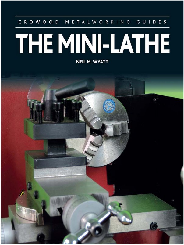
If you are thinking of buying one of the several flavors of Mini-Lathes (7X10 to 7X16), or already own one, this is a must have book!
I am not a professional machinist, nor would I claim to be a highly skilled one, just a hobbyist. I have, however, rebuilt two 12 inch Atlas lathes, and spent a fair share of time using them. I recently had to sell my last Atlas, and as part of the deal, picked up the new owners old Harbor Freight 7X10 mini-lathe.
When I started with my Atlas lathes I bought several good books on using and maintaining a “Full Size” lathe, including the Atlas and Southbend manuals, and used much of what I learned. This book is the equivalent for the mini-lathes.
This book is filled with chapters on the construction of various vintages of these lathes, discussions of how to adjust them for better precision, and work piece finish, and easy modifications to improve their range and usefulness. The book is also fair in pointing out the strengths and weaknesses of a mini-lathe.
The book explains how to use the lathe for those who have never used one, as well as several projects that you can use to improve the lathe and your skills at the same time.
I would recommend the book to those who have been using this type of lathe for a while, if only for the adjustment tips, examples of after-market accessories available, and the projects. Many of the adjustments are the same as for a larger lathe, but there are also many specific to these types.
-
-
To protect softer metals and wood, used brass or aluminum shims between the jaws and the work peice, and tighten the jaws enough to hold the piece, but not distort it.
- keelhauled, Canute, bruce d and 1 other
-
4
-
-
-
On a note about the C/D model shown above. As I'm sure you know the later models had the spine at the tail, and a tailgunner. With the earlier models, there was no room for a tail gun. That is not the reason the spine and thicker aft fuselage was added though. During a flight in an earlier model B-17, it encountered a violent storm. As the crew desperately tried to make it to an airfield, the tail was twisting around so badly that the rivets were failing and the aft section of the plane was slowly coming apart. Finally the pilot ordered the rest of the crew to bail out while he fought to keep the plane in the air. The crew made it out safely, but the pilot, who could not leave the controls, without the plane immeadeately crashing, died when it finally came apart. After this, is when they added the spine to stiffen the tail, and then had room to add a tailgun.
- mtaylor, popeye the sailor, Canute and 2 others
-
5
-
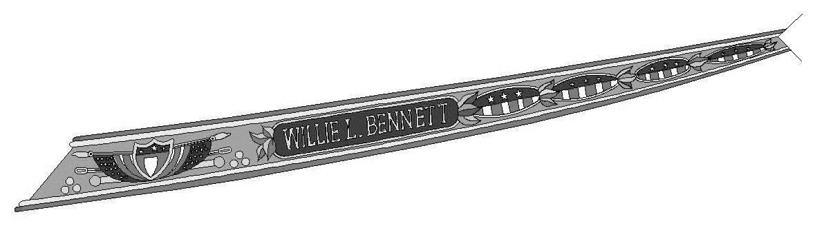
DesignCAD has a curved line tool, that follows the points you give it, to give a smooth line for a frame, etc.
An example it this trailboard I made by tracing a scan from the ME Willie Bennett plans, using the curve line tool. I gave them this graphic and they now supply in their kit. Their graphics are color, I made this starboard one grayscale, so as not to infringe on them.
-
The weird thing about the German bombers, is that they never developed a 4 engine bomber, even though they had a 4 engine airliner, that they used as a reconnaissance aircraft. They used them to track Naval and convoy ships.
- popeye the sailor, mtaylor and lmagna
-
3
-
I'll be following this. I have the same kit in my stash.
-
making parts
in CAD and 3D Modelling/Drafting Plans with Software
Posted
That depends on the scale you are thinking of. Thought, in general, you would need to 3D print in plastic, and that brings in issues of failure of the plastic, over time due to the tension from the rigging. The fine detail plastics are brittle and quite weak, in thin sections.