-
Posts
2,421 -
Joined
-
Last visited
Content Type
Profiles
Forums
Gallery
Events
Everything posted by usedtosail
-
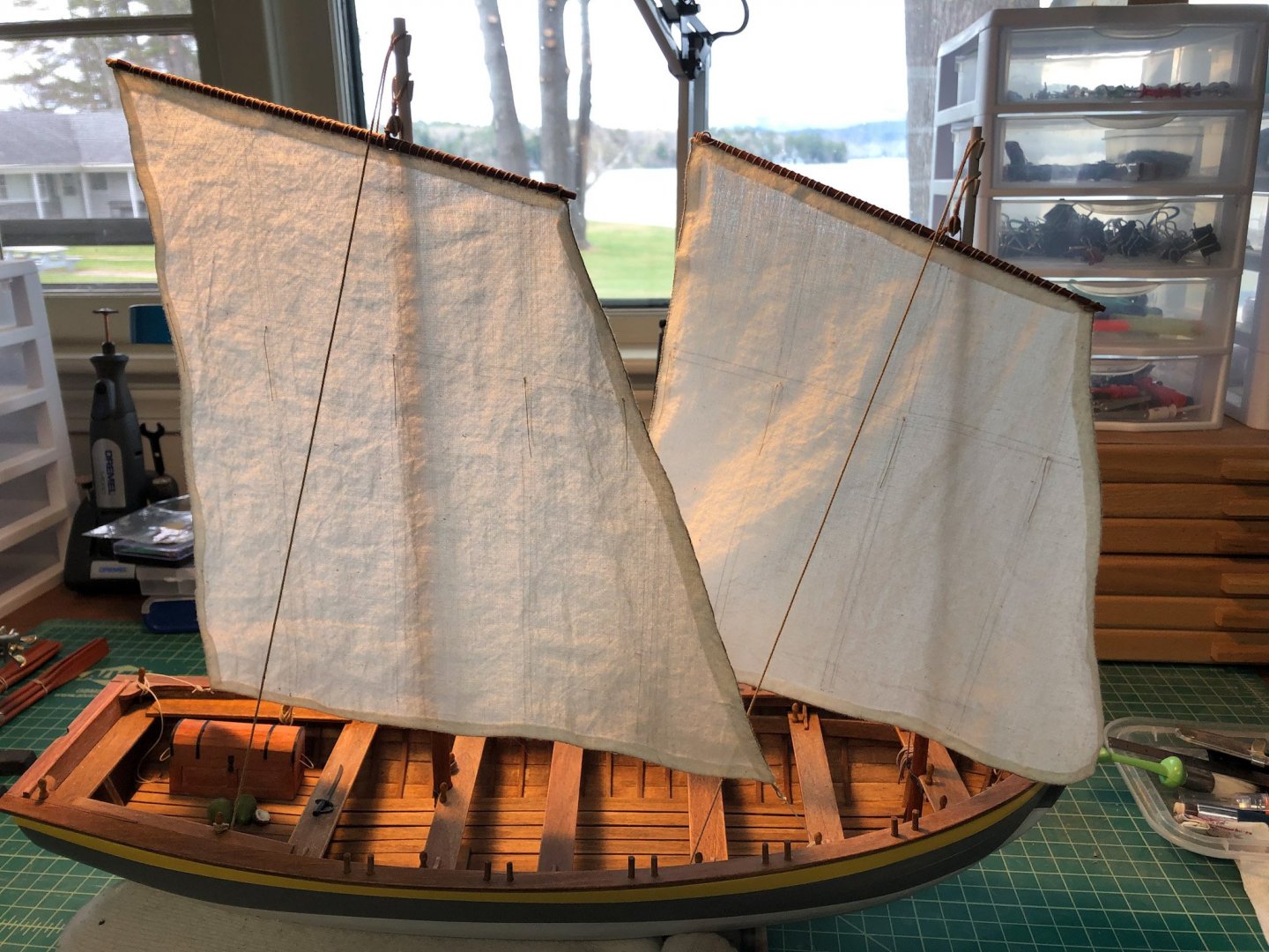
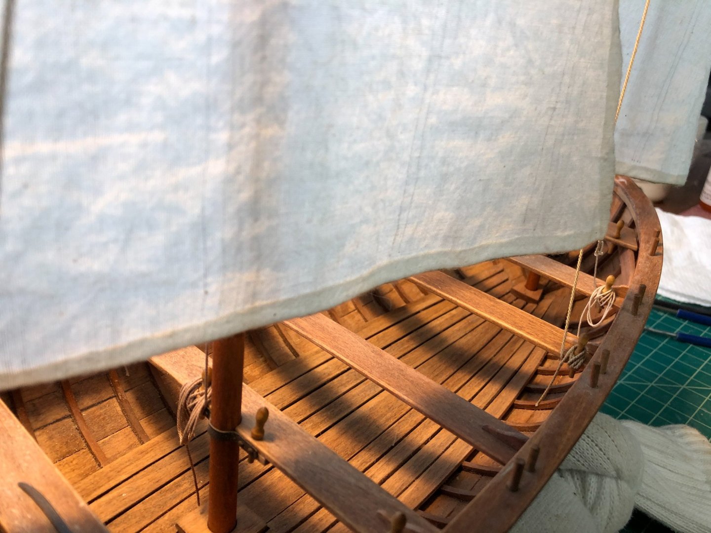
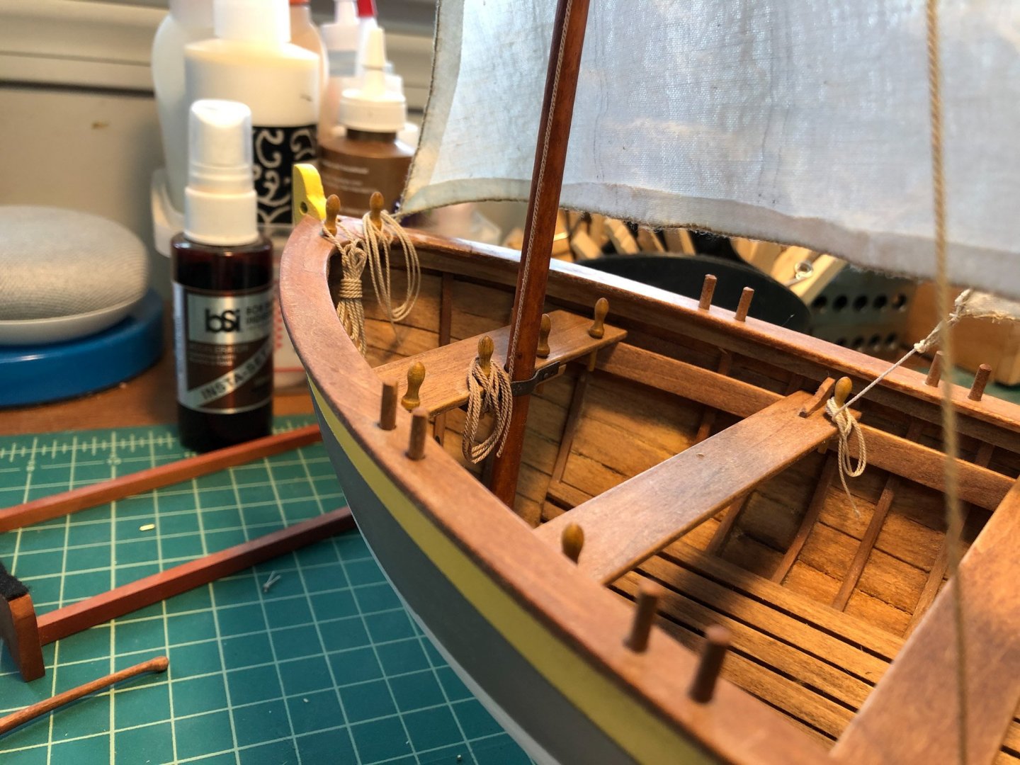
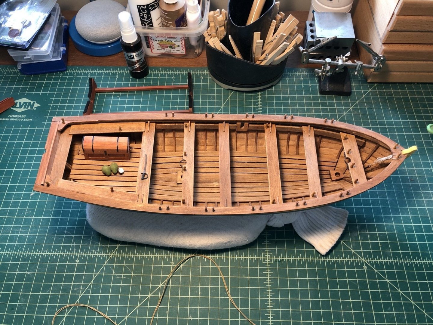
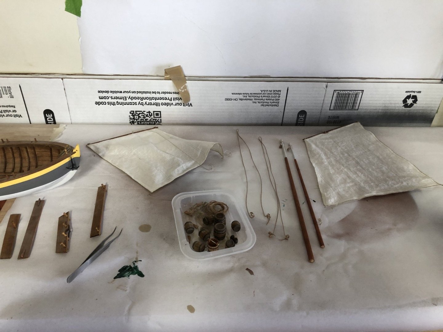
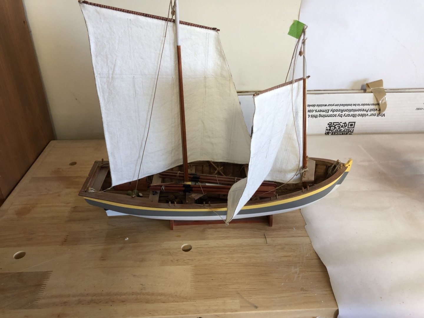
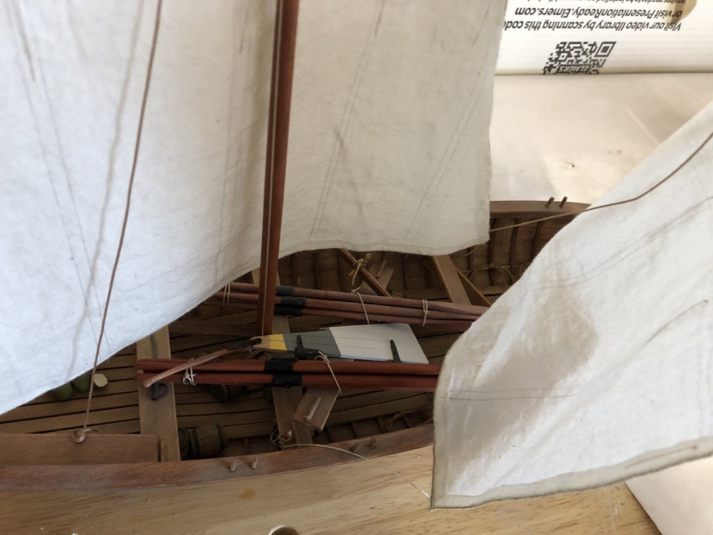
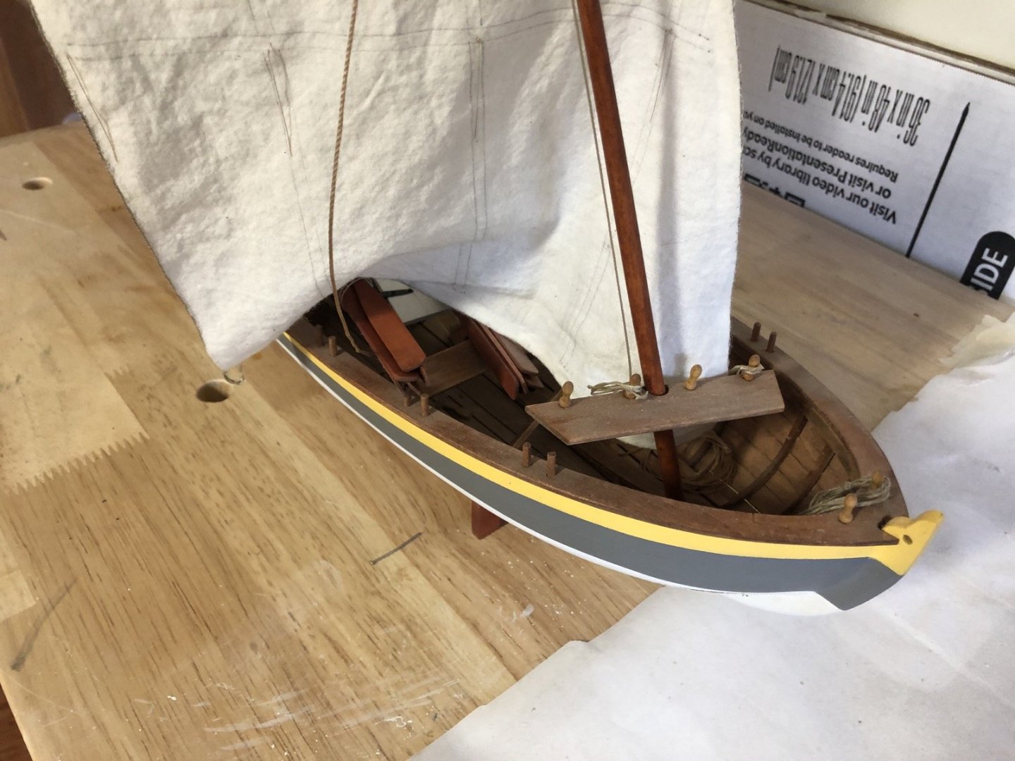
I put the masts back in and added the new shrouds. I then replaced all of the lines on the sails with better rope and hoisted them onto the masts. I arranged them differently than they were before but I think it gives a better view into the boat. I was able to wrap all the excess lines onto the belaying pins making rope coils from the actual lines so I did not have to make any separate rope coils. I used micro clips to hold the coils together and weight them down then I brushed diluted white glue onto them. I am really pleased with how this new version is coming out.
- 153 replies
-
- model shipways
- bounty launch
-
(and 1 more)
Tagged with:
-
That's a good idea Keith. I will look into that.
- 153 replies
-
- model shipways
- bounty launch
-
(and 1 more)
Tagged with:
-
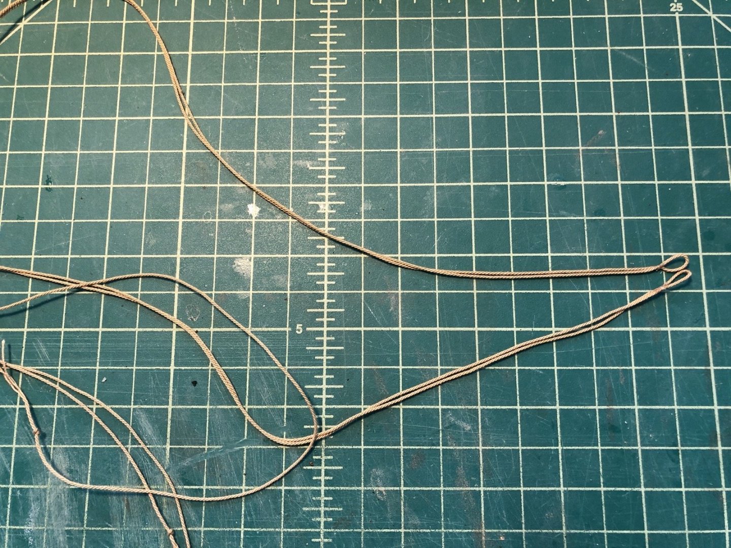
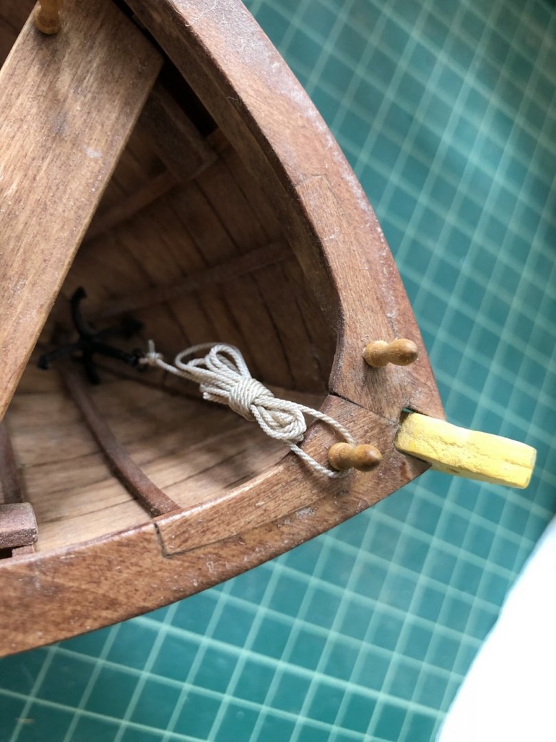
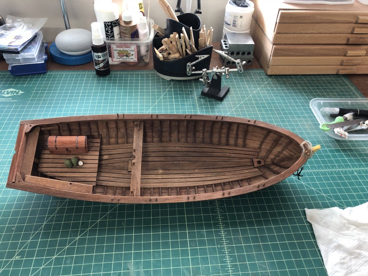
I glued all the cleaned up thwarts back in. I made new shrouds using rope that I made instead of the crappy rope that the old shrouds were made from. I used some crappy looking cotten rope from some old kit and spun it up on the rope walk to make a thicker rope, which looks really good. I also replaced the anchor rope with some rope I had made for the Constitution. Again, it is much better than the crappy rope that came with this kit.
- 153 replies
-
- model shipways
- bounty launch
-
(and 1 more)
Tagged with:
-
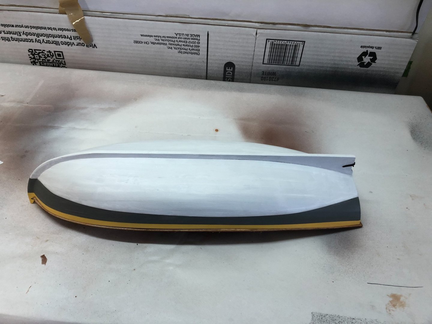
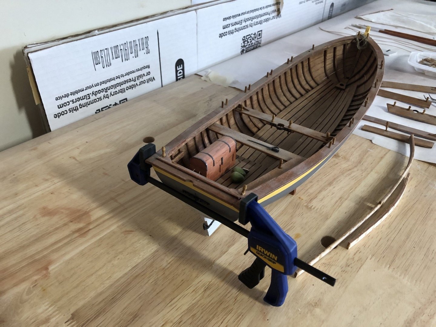
The filler could been seen from inside the hull so I touched it up with some Cherry strain. I also touched up the black paint on the toolbox straps. I then have the white part of the hull a couple of coats of thin white paint. When that dried I glued the thwart supports back into the hull.
- 153 replies
-
- model shipways
- bounty launch
-
(and 1 more)
Tagged with:
-
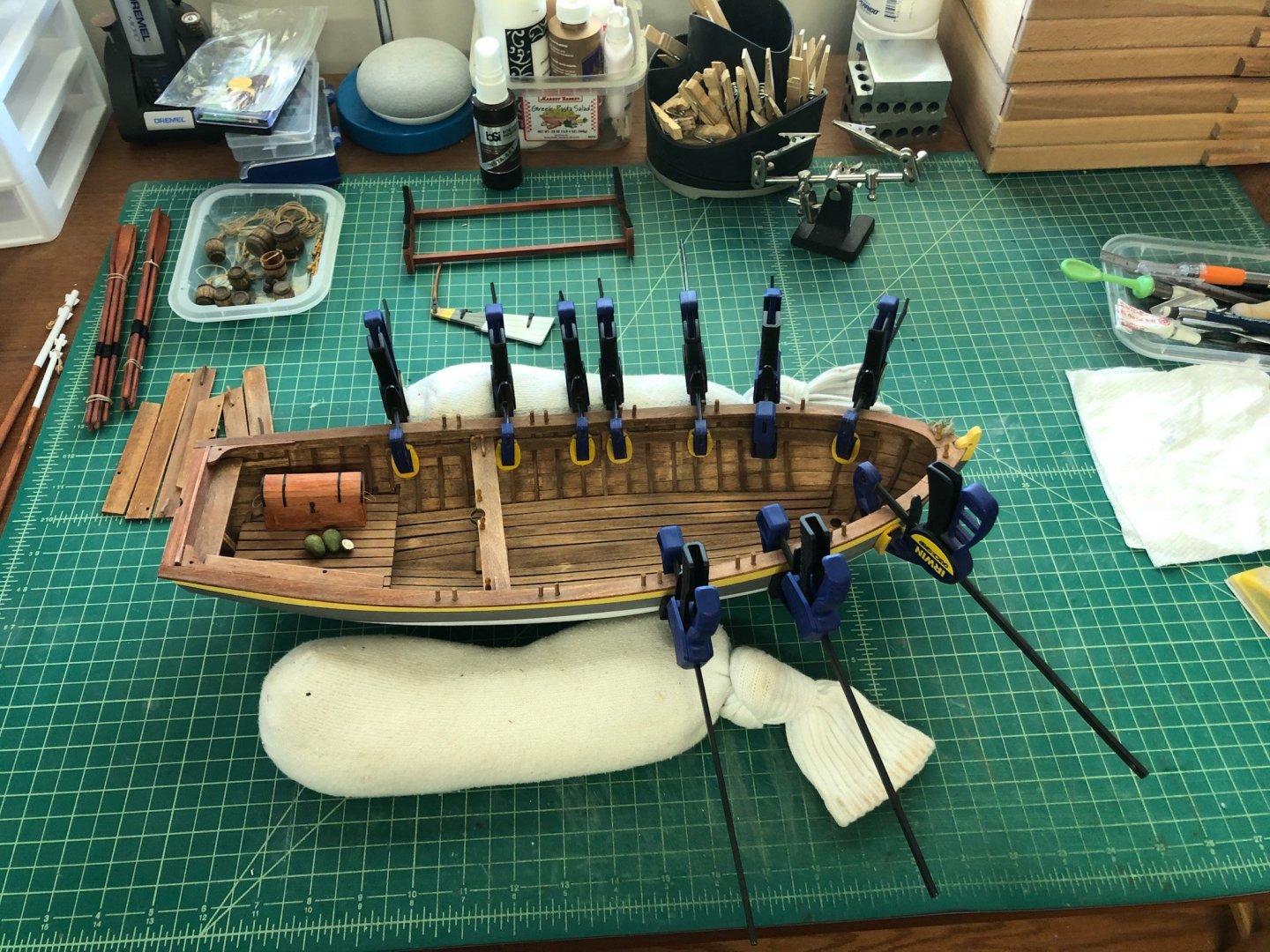
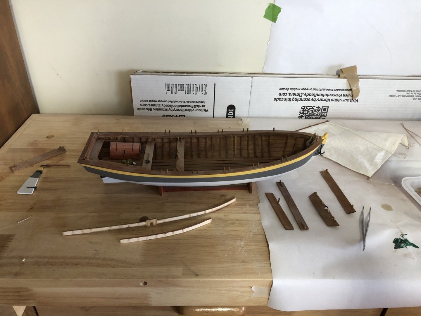
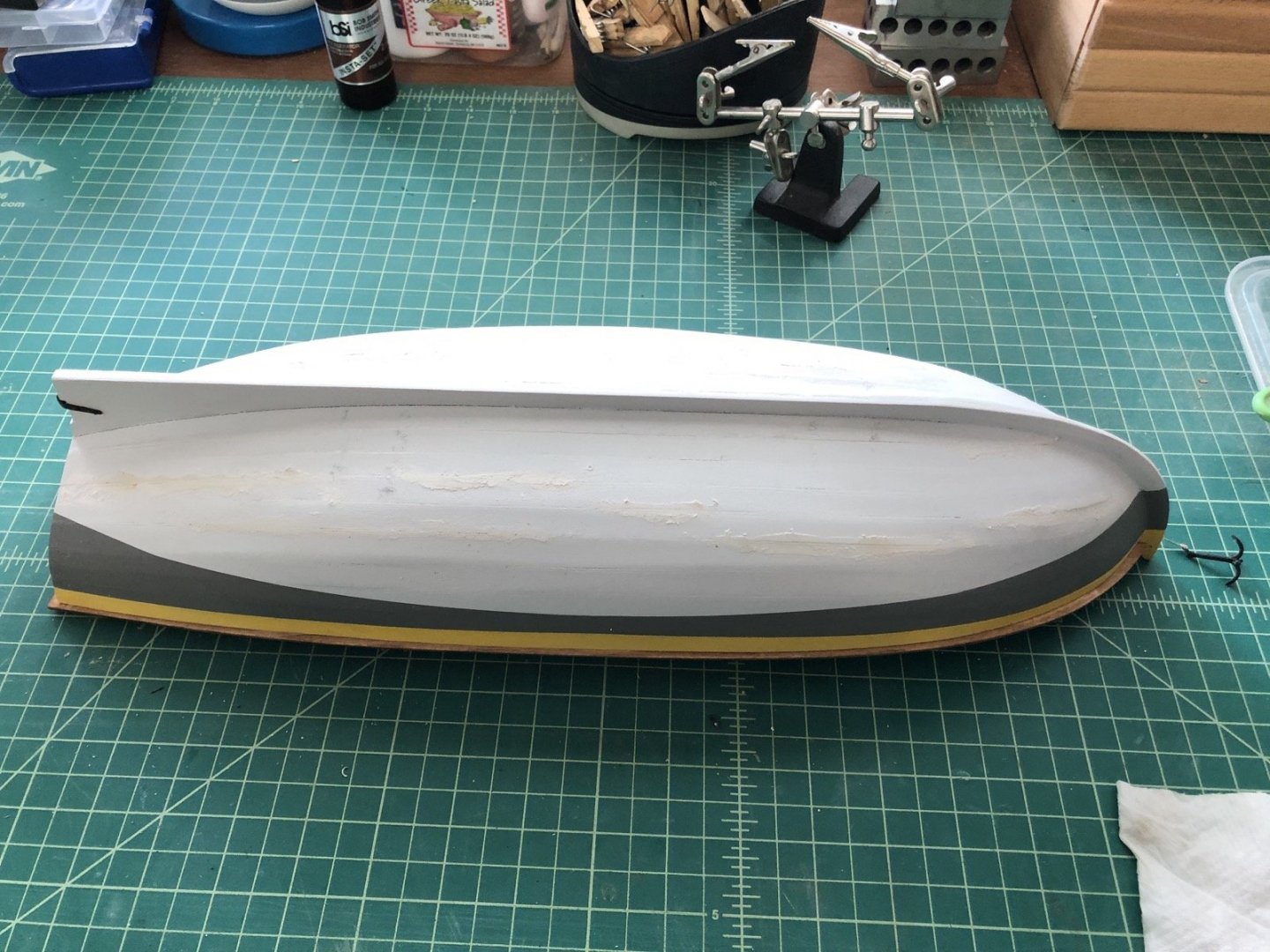
I started out by just separating the loose parts. For the rigging, I was able to loosen up the lines around the belaying pins so I could remove the sails with the rigging intact, at least for now. I then re-glued the aft corner that had come loose. You can really see how dusty it is inside the hull in that last picture. So the next step was to clean all that dust out. I used Q-Tips with a little water and wiped all the surfaces, which worked nicely. The next step was to fill the cracks in the hull with wood filler. This will be sanded off when it dries and I will then touch up the white paint. In the mean time I am cleaning the dust off the detached pieces and figuring out if I will re-rig the masts and sails.
- 153 replies
-
- model shipways
- bounty launch
-
(and 1 more)
Tagged with:
-
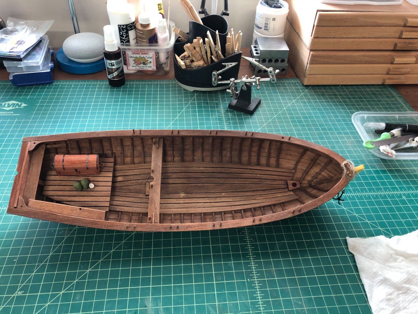
Well, the Bounty Launch got launched. It was the only model in the house not in a case and a cushion caught the mast as the Admiral was getting it. Not a huge deal because I could tell it was not aging well and needed some attention anyway. Here is how it looks back on the bench after the accident. Nothing is actually broken. Most of the thwarts have been dislodged due to the pull of the rigging. I will probably take the time to redo all the rigging as I have better rope I can use now. The stern starboard corner is loose but it was like that before the fall. There are also a few cracks in the planking that need some attention. I can also clean out all the dust that has accumulated over the years inside the hull. Luckily this happened just after I finished the Chris Craft and before I have started the Half Moon.
- 153 replies
-
- model shipways
- bounty launch
-
(and 1 more)
Tagged with:
-
Hi Dave. I just found your build log and will follow along. You are doing a great job. I really like the look of your copper plating. If I may give you one note of caution is that to make sure the chain plates will take the strain of the rigging just being glued to the hull, unless the lower deadeyes are held securely in the channels so they would take the strain.
- 55 replies
-
- constitution
- model shipways
-
(and 1 more)
Tagged with:
-
Thank you cleat and Jeff. The case is 1/8 inch Plexiglas that I had left over from a previous project. In the past I have cut it on a table saw with a blade with a lot of teeth per inch. For this one I just used my table top band saw with a normal blade. The edges were a little rough but some light sanding took care of that.
-
Thank you Chris and Popeye. Popeye I thought you had finished your Half Moon. Don't start it back up yet. It's going to take me a while to get to where you are so finish up those other projects first.
-
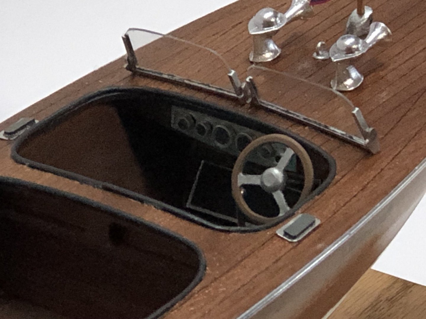
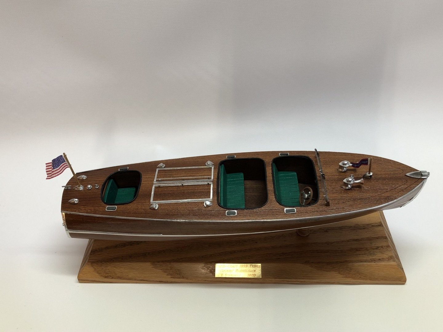
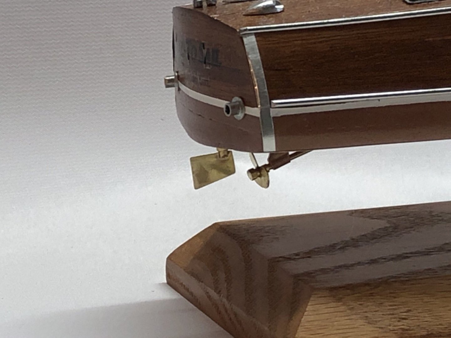
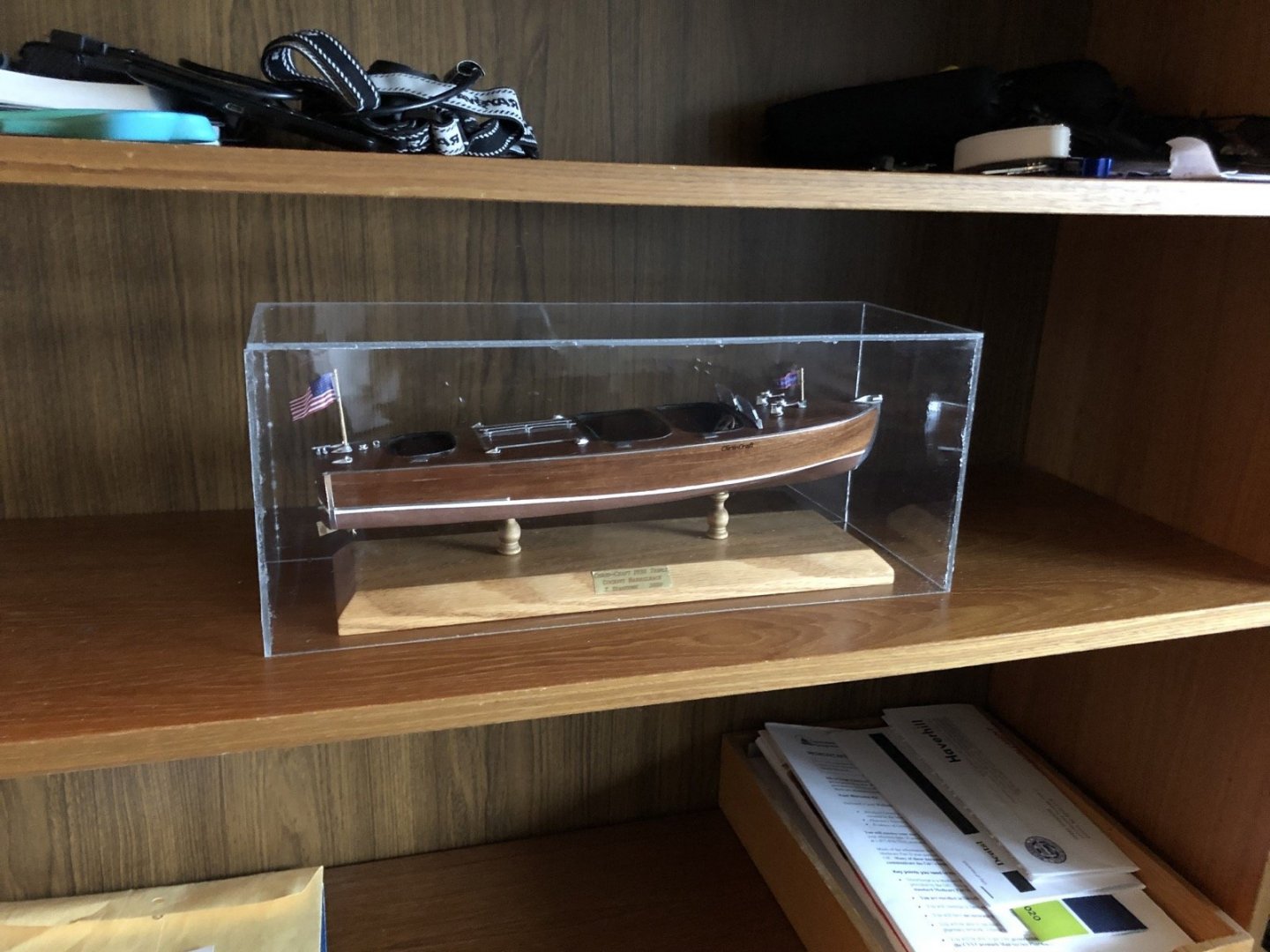
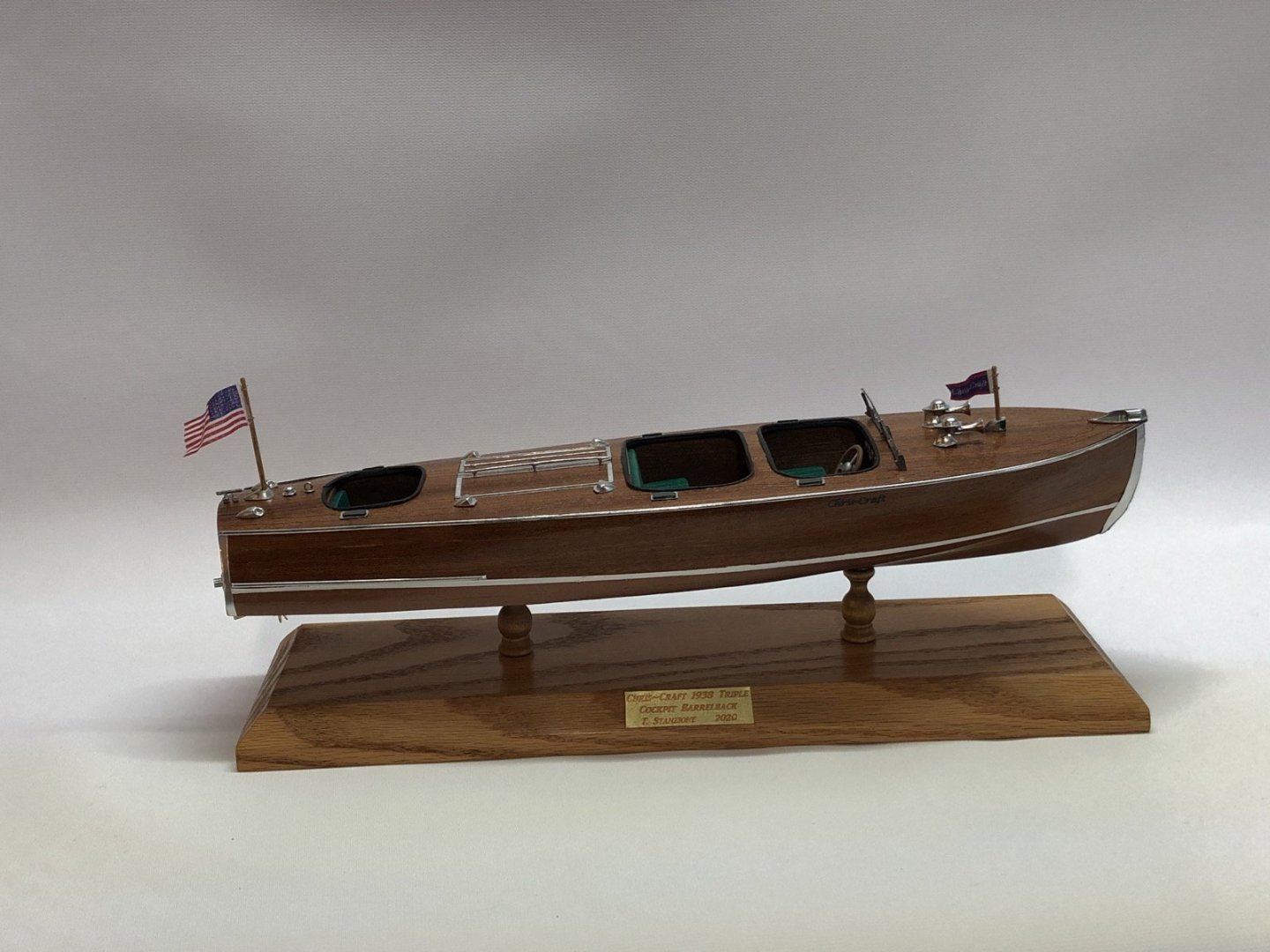
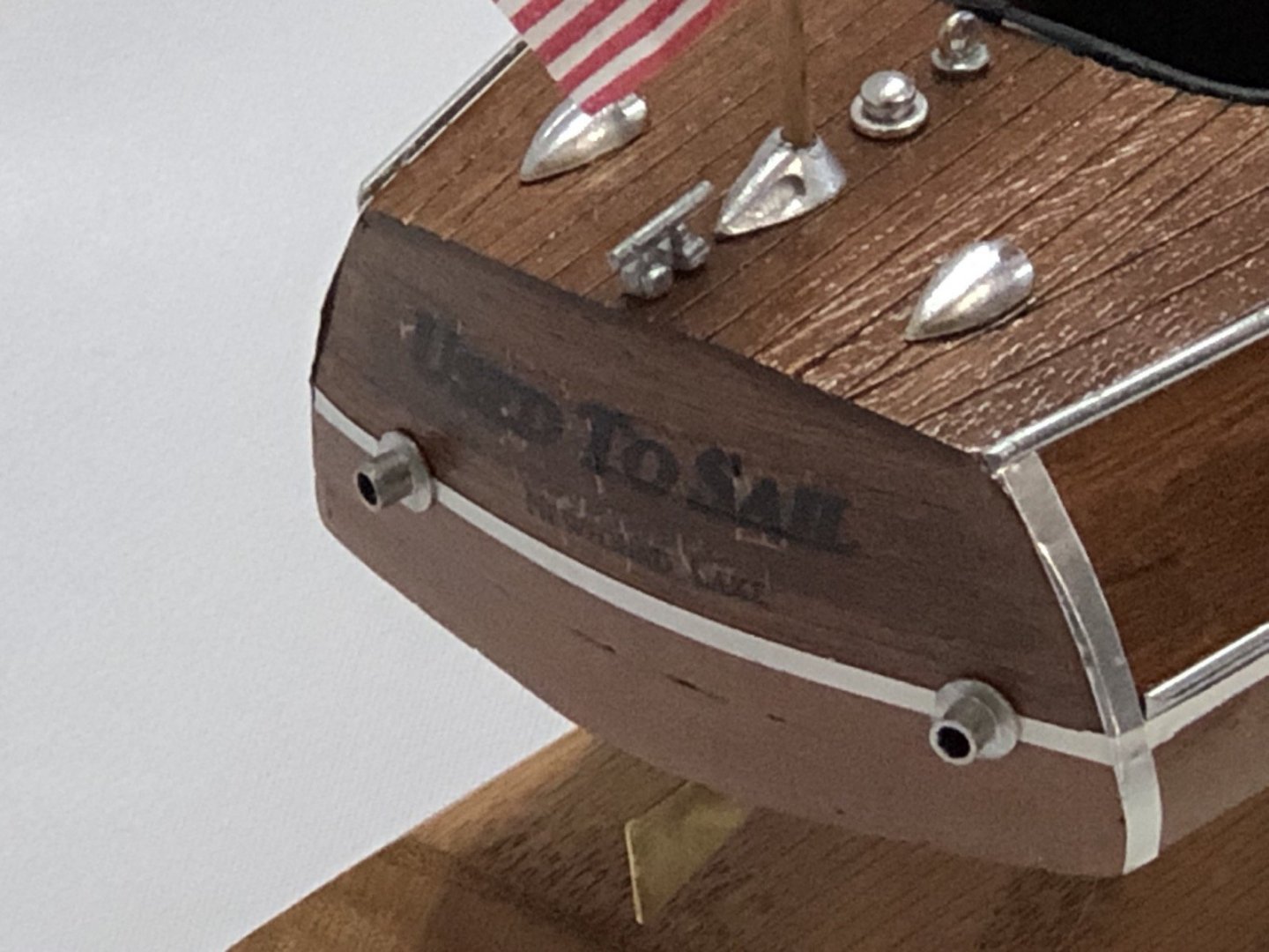
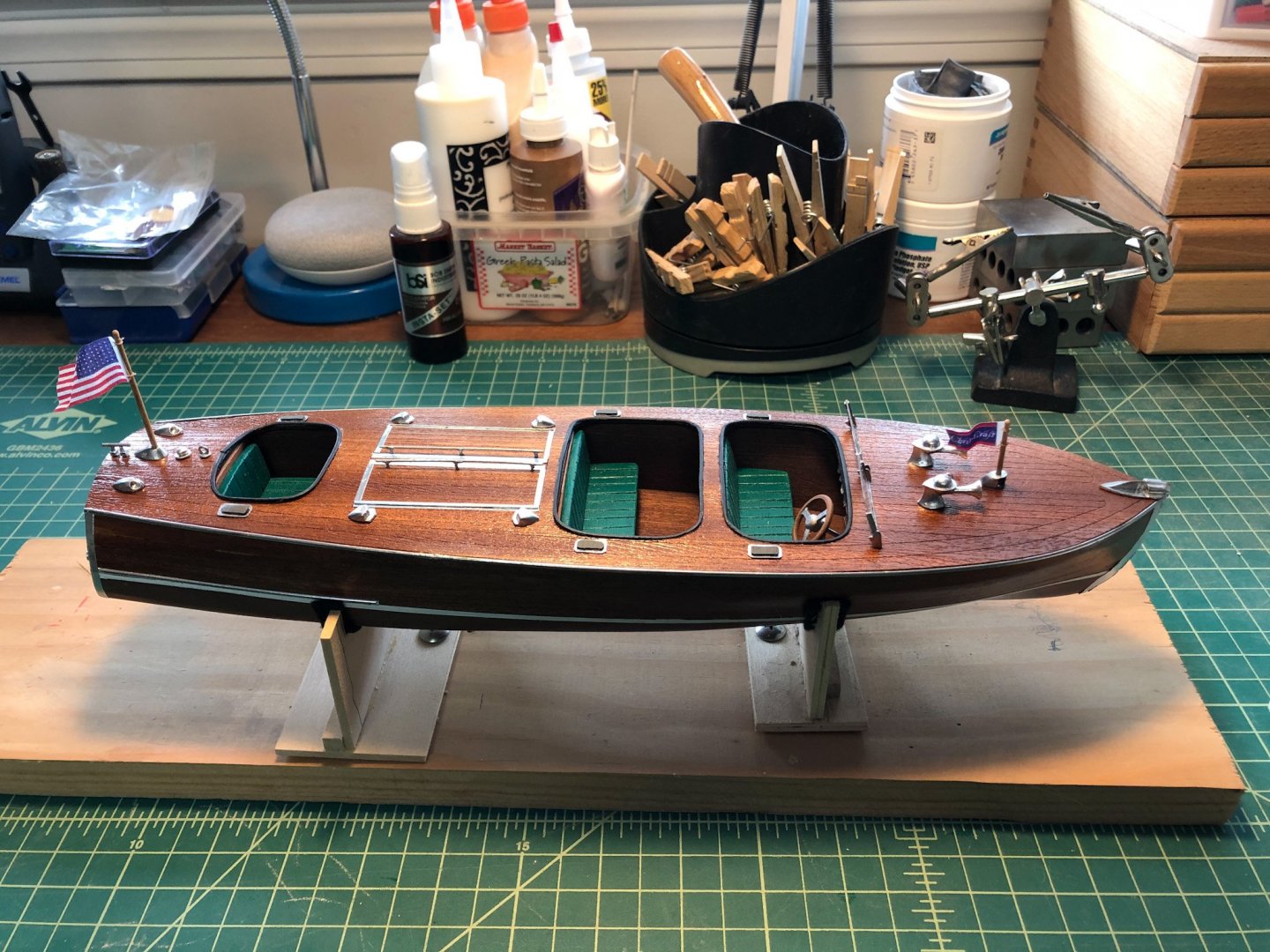
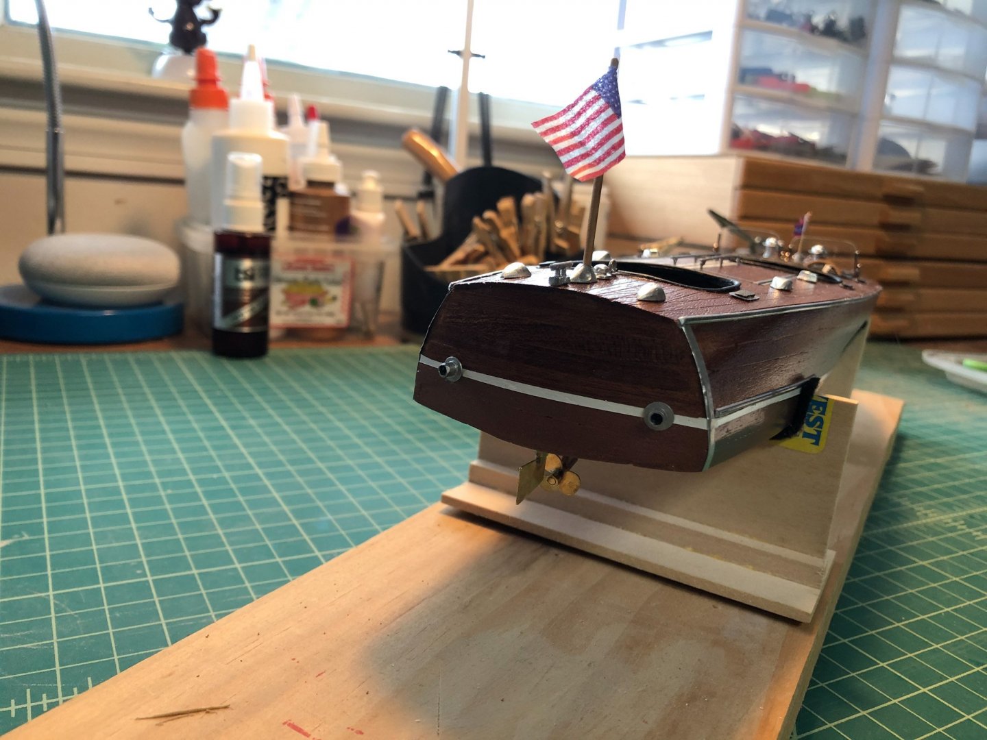
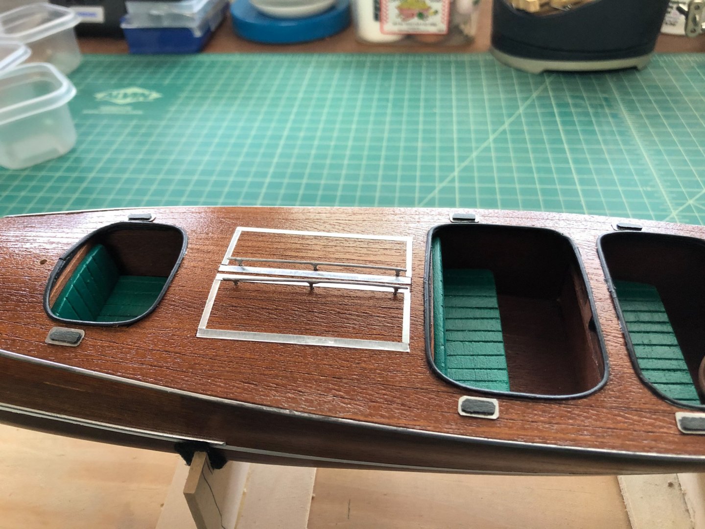
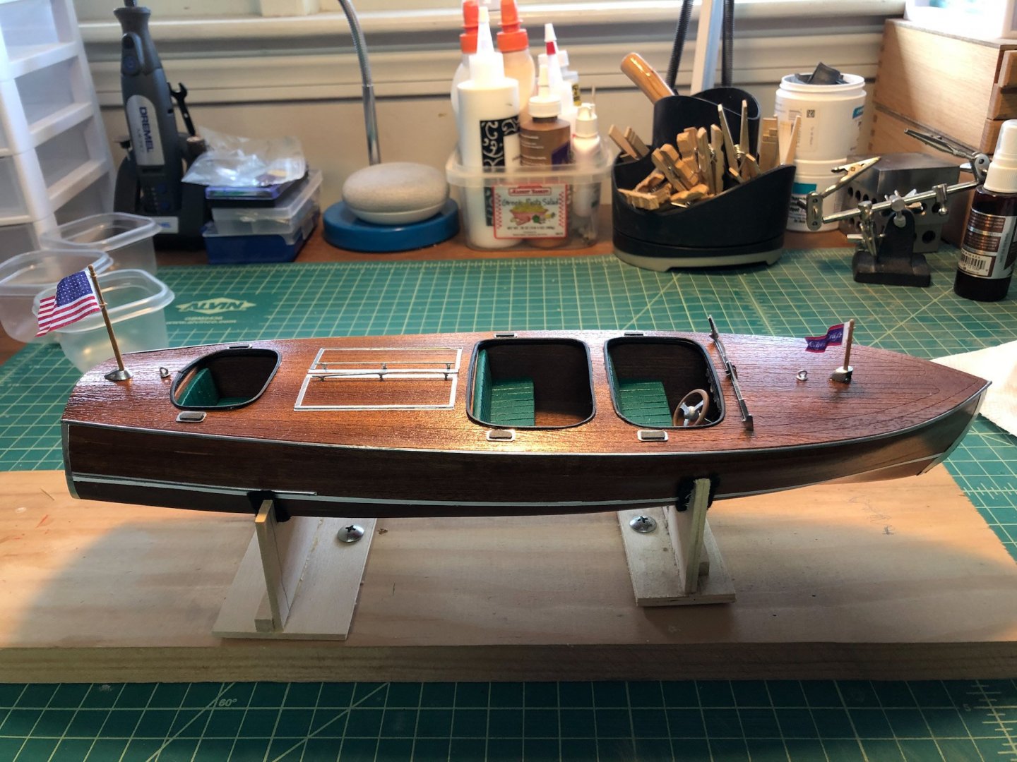
Thanks cleat and Popeye. This was a fun little project despite the issues with the mahogany. Adding the name to the back was a small project in itself. The first round of decals I made up didn't show at all on the hull. I was going for some fancy gold lettering but the printer just couldn't get it dark enough. For the second attempt I tried white letters which again did not show up well. I finally made some decals with black letters that did show up. The logos are also done in black so they can be seen. I used a product called Micro Set to place the decals and they looked pretty good, but then I tried a product called Micro Sol that was supposed to make them set even better. It did the opposite and bubbled up the decals and made them very soft so that trying the flatten them messed them up even more. So I took those off, made another set and placed them with just the Micro Set. They are not as nice as I would have liked but they will do. Here are some pics of the completed model, and I will add some more to the gallery. Now before you think I am too narcissistic, my screen name actually came from the name of my first full size power boat. I had always had sailboats before that so I was more "used to sail" than I was power. So I had to name my first power boat model the same.
-
Thanks Cleat, Popeye, and stuglo, and the likes. For my next build I chose the Billings Half Moon. I was inspired by Popeye's and JCT's builds of this ship. I've had the model for a while and it is now at the top of the queue. Still a little more work to do here first though.
-
Great build. Your students are very lucky to have you.
- 168 replies
-
Just about done now. I glued on the rest of the details to the deck and transom, and also the prop and rudder. Only one more thing to add - a name on the transom and the logo. The kit supplied a couple on the sticker sheet but I am not using them. I made a decal sheet with the name and the logos but I am waiting to receive some Micro Sol to get the decals to lay down better. Should be here tomorrow.
-
You are doing a great job Cleat. That finish is gorgeous. I like the way you made your seats too.
- 36 replies
-
- chris-craft 1956 capri
- dumas
-
(and 2 more)
Tagged with:
-
I have his vertical rope walk which I converted to use horizontally. It works great for me. I did have to replace the power supply but they are cheap and easy to find.
- 11 replies
-
- block seizing serving
- serv-o-matic
-
(and 1 more)
Tagged with:
-
Very very nice build Jesse. The flags are exceptional.
- 1,306 replies
-
- syren
- model shipways
-
(and 1 more)
Tagged with:
-
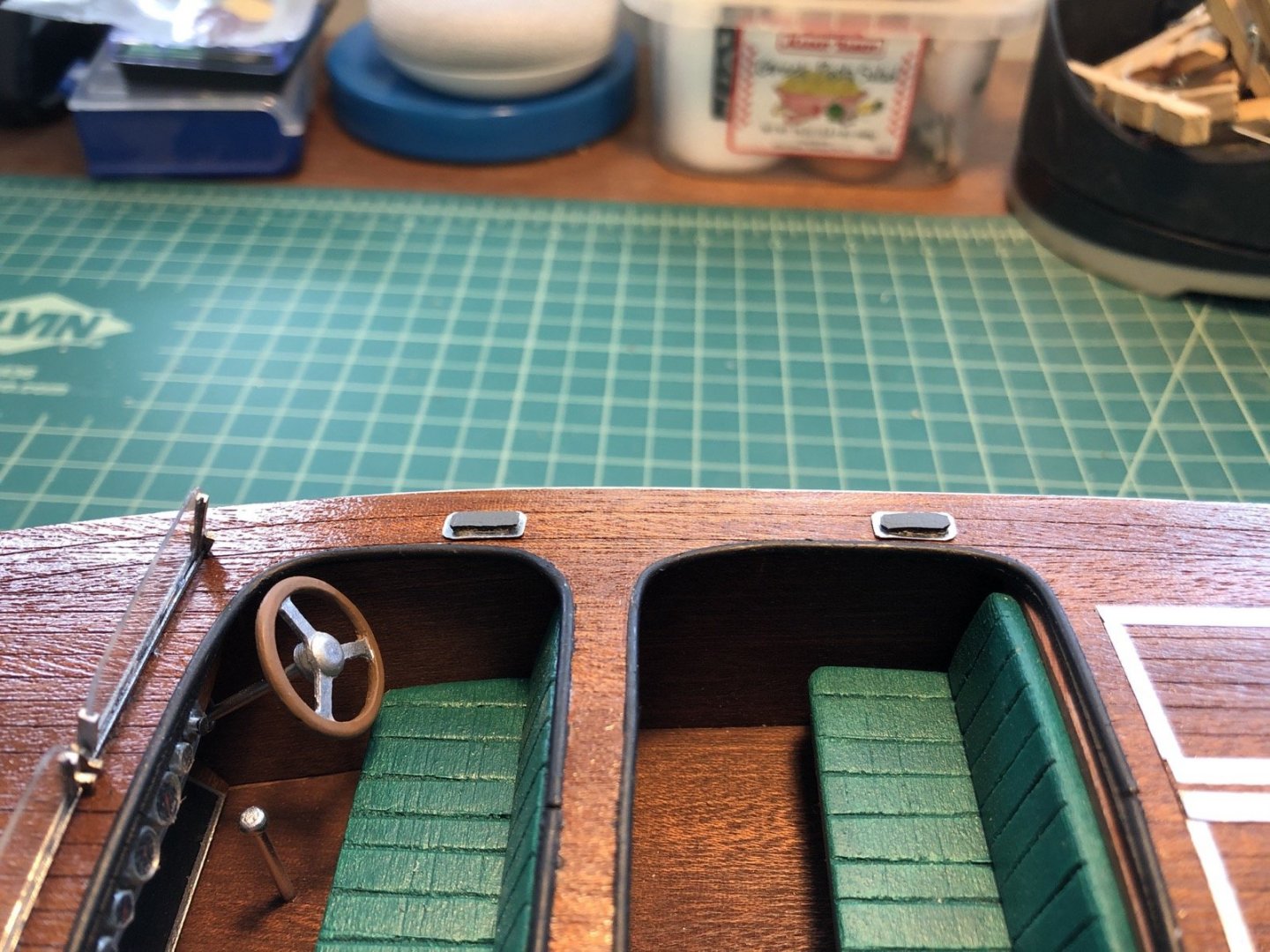
Now it was time to drill the holes for the hatch handles. The thought of this actually kept me awake some last night because I only had one shot at this. Drilling three holes in a straight line by hand for each one was a bit daunting. I thought about using that wood strip with the holes as a jig but it was too clumsy so I instead laid the handle down on the deck and used them directly to get the positions of the holes. Well I had no problem getting the holes right and the handles fit right into the deck. With that of of the way I starting installing the other details I have been working on, including the hinges, flag staff, jack staff, and lifting hooks. I have more details to add and I am working on some decals for the transom. It won't be long now.
-
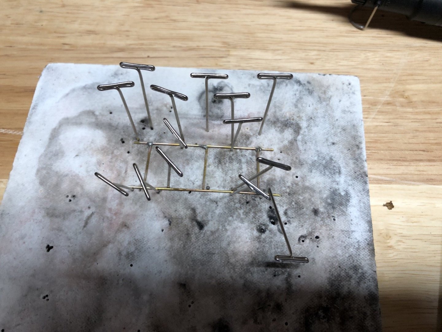
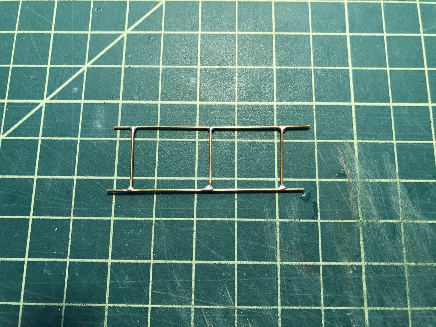
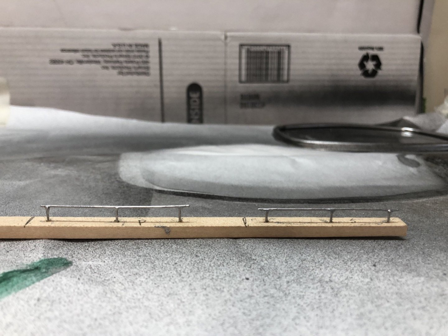
I made the handles for the engine hatches this afternoon. The instructions wanted me to glue the brass rod pieces together using a wooden jig. It might have worked but I would be afraid of knocking them loose as I glue the rest of the details on. So, using what I learned in those excellent soldering videos that someone posted recently, I decided to try soldering them together. In order to make two that were the same, I made them as one piece and then separated them later. I cut the brass rod pieces to length, making sure the three short pieces were exactly the same length. I then laid out the shape using T pins to hold the rod pieces in place. I also used three T pins to mark the locations of the short pieces so I didn't have to keep remeasuring as I got them into position. Once they were in place I carefully added flux and small bits of solder to each joint, then heated each joint with a butane pencil torch. I took this picture after the first round of soldering. The two center joints were reheated with more solder as the first pass didn't come out well. The other four joints were fine. I pulled the pins out and started cleaning up the excess solder with files. This was the crucial test because if the joints weren't good this handling would probably break them. Everything stayed together and I then cut the center supports so I had two equal handles. I cut the ends of the handles and filed them a bit rounded then test fit them in a scrap strip of wood. I left them in the wood and painted them with aluminum paint. I am hoping I can use the wood strip as a jig to drill the holes in the hatches. Overall I was pleased with the result. I have never been able to do this fine kind oif soldering before, even if I know it is not perfect.
-
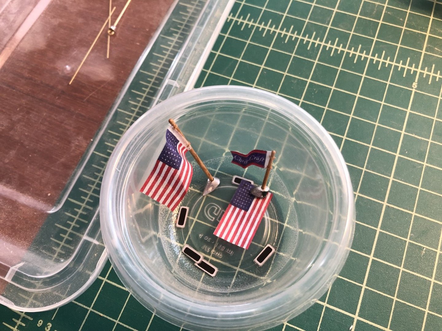
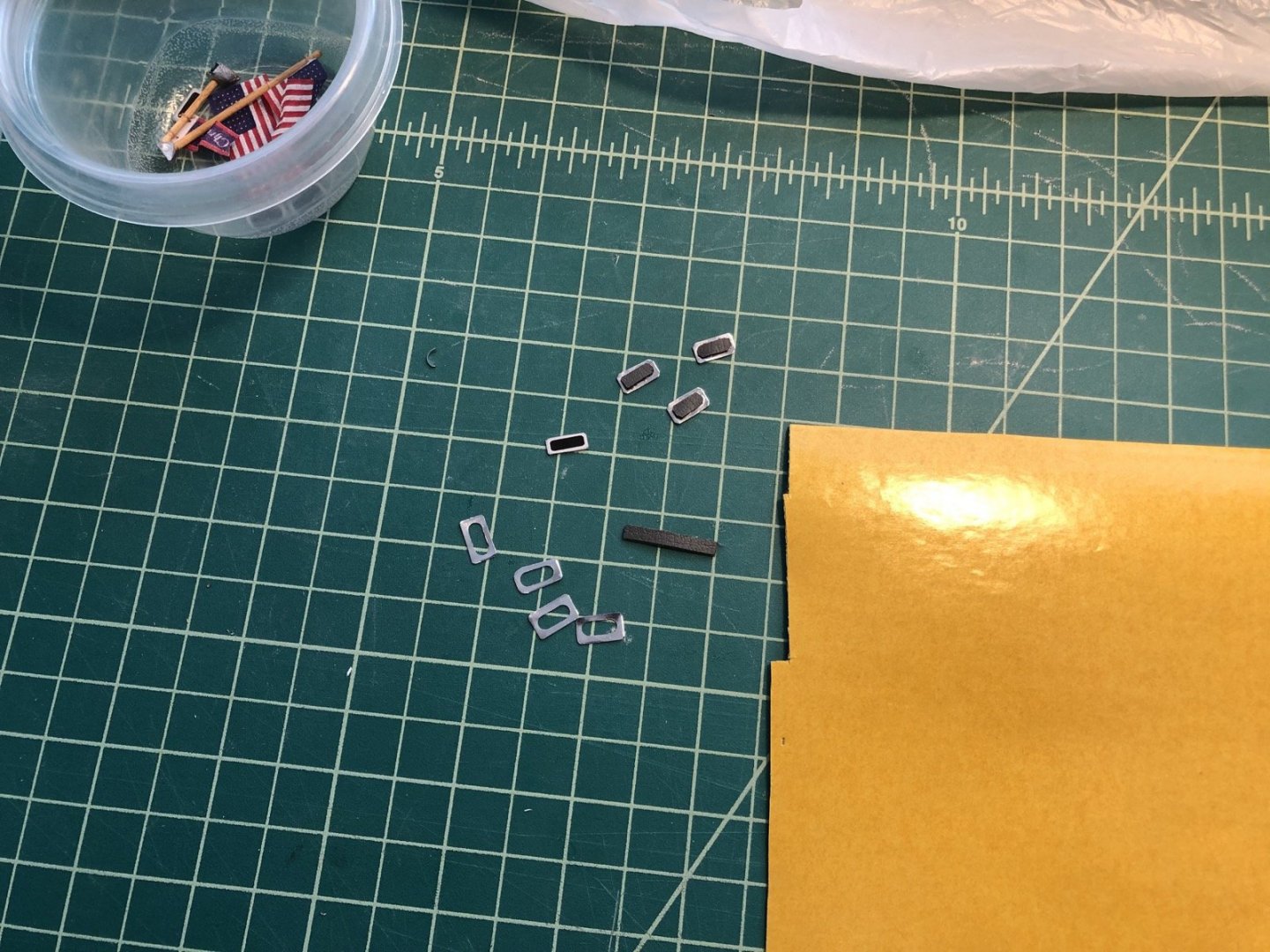
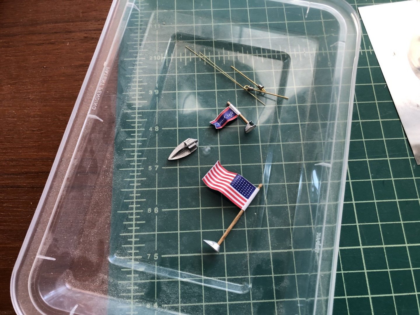
Hello Cleat. Welcome to the build. To answer your questions, the aluminum planking clamp is something that I made from 2 pieces of aluminum angle iron I got from Home Depot. I cut them to about 14 inches in length, then drilled holes through one and tapped the other one so I could screw in those screws that you can hand tighten, also from Home Depot (I forget what they are called). The Spaz Stix has a black spray that you use before the chrome. It is supposed to make it easier to see spots you may have missed with the chrome. You can really use any color under the chrome. Are you going to add a build log? I would love to see your project. I cut the flags and tied them to the flag and jack staffs. I ended up redoing the pennant using the inkjet printer because the ink on the laser jet one was scrapping off as I cut it. Here are the new flags on the staffs. I then made the new foot steps for the deck. In the above picture you can see the kit ones which are just a sticker on a piece of plastic. I wanted something with more depth so I remade them using some thin aluminum sheet and some thin rubber that I had. I first mounted the sheet in the mill and cut a series of holes. I was able to use scissors to cut the steps around the holes, although they were a bit too wide. I cut the rubber into a thin strip and then cut lengths of that to fit the holes, rounding the ends a bit. I was able to push these into the holes from the bottom and get them to stay. I again used scissors to cut the steps narrower and then glue them to the hull with Hypo cement. I like the way they have some depth now. Not perfect but I think better than the plastic. Next I need to make the handles for the engine hatches and add the hinges.
-
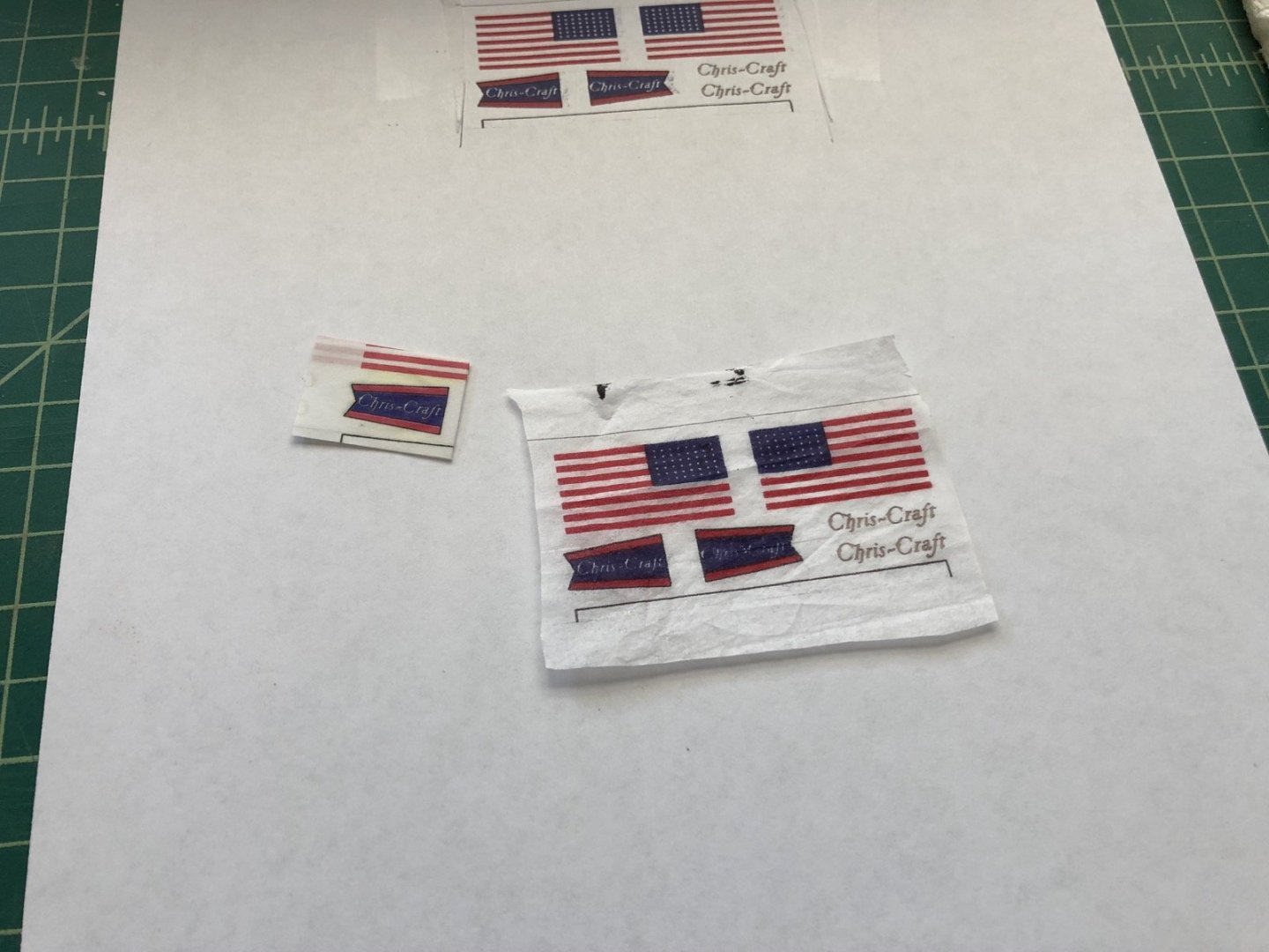
I made the jackstaff and flagstaff from a wooden dowel instead of the plastic rod that came with the kit. The plans show a ball on the top of these but the plastic was too narrow. I used the lathe with files and sandpaper to make them. I tried using the supplied flags which are adhesive plastic and of course they looked terrible. I had made a copy of the sticker sheet and used it to make paper flags, which I wrapped around the staffs after finishing them with oak stain and WOP. They looked OK but I knew I could do better. So I broke out my old inkjet printer and spent a few hours getting it working again as the ink had dried up pretty badly. Once it was working again I printed the sticker sheet on vellum paper. I had to use this for the Chris Craft pennant because of the writing on it I needed two different sides. I carefully folded and glued the two sides together. I printed the flag on tissue paper so I can use only one layer since the inkjet ink shows on both sides. Once I cut these out I am going to tie them to the staffs instead of wrapping them around. For the other stickers, like the Chris-Craft logo and the name on the transom, I am going to try to make a decal sheet. I have the materials but have not tried it before so there will be some learning curve there. You can also see in the first photo the fairlead which goes on the bow. I carefully drilled two holes to open up the tubes and touched up the paint, so it is ready to go. What is not shown is the bow light which I painted red and green in the lens area. The lifting eyes are shown which are supplied as an eyelet and a eyebolt, which you are supposed to glue together and then glue into the deck. The problem is the hole is so large in the eyelet that there would be a hole around the eyebolt. My solution was to fill the hole with Sculpey then put the eyebolt in, then bake them to harden the Sculpey. I now have to paint them and trim the ends of the eyebolts. The two pieces of thin rod I am going to use to simulate the hinges on the engine hatches by painting them and then gluing them on the metal frames. I have also decided to not use the plastic foot steps and I will try to make them from metal sheet and some thin rubber. More on that later.
About us
Modelshipworld - Advancing Ship Modeling through Research
SSL Secured
Your security is important for us so this Website is SSL-Secured
NRG Mailing Address
Nautical Research Guild
237 South Lincoln Street
Westmont IL, 60559-1917
Model Ship World ® and the MSW logo are Registered Trademarks, and belong to the Nautical Research Guild (United States Patent and Trademark Office: No. 6,929,264 & No. 6,929,274, registered Dec. 20, 2022)
Helpful Links
About the NRG
If you enjoy building ship models that are historically accurate as well as beautiful, then The Nautical Research Guild (NRG) is just right for you.
The Guild is a non-profit educational organization whose mission is to “Advance Ship Modeling Through Research”. We provide support to our members in their efforts to raise the quality of their model ships.
The Nautical Research Guild has published our world-renowned quarterly magazine, The Nautical Research Journal, since 1955. The pages of the Journal are full of articles by accomplished ship modelers who show you how they create those exquisite details on their models, and by maritime historians who show you the correct details to build. The Journal is available in both print and digital editions. Go to the NRG web site (www.thenrg.org) to download a complimentary digital copy of the Journal. The NRG also publishes plan sets, books and compilations of back issues of the Journal and the former Ships in Scale and Model Ship Builder magazines.


