
HOLIDAY DONATION DRIVE - SUPPORT MSW - DO YOUR PART TO KEEP THIS GREAT FORUM GOING! (83 donations so far out of 49,000 members - C'mon guys!)
×

popeye2sea
-
Posts
1,935 -
Joined
-
Last visited
Content Type
Profiles
Forums
Gallery
Events
Everything posted by popeye2sea
-
I have seen it done so that you end up with a reef point at 1/3 (or 8") intervals on each cloth, but I am sure there are other ways. I read a description whereby robands are put in two to a cloth with one falling on the seam, perhaps reef points could be done the same? You will end up with different patterns across the sail. The first produces groups of two with a larger gap between groups. And the second will produce an even spacing. Choose the one that looks best to your eye. Regards,
-
 Chuck, the standard in the last post is for the Kingdom of Great Britain, established and adopted by Queen Anne in 1707. Queen Anne first used the Royal Standard you show in the earlier post ( Fleur-de-lis and lions in the first and fourth quadrant). This was called the Royal Standard of England, first adopted in 1603. Regards,
- 269 replies
-
- 5
-

-
- Queen Anne Barge
- Syren Ship Model Company
- (and 1 more)
-
There were generally 2 reef points in each sail cloth, evenly spaced between the seams. Regards,
-
There is also a bolster fitted below the hawse holes. Sort of a quarter round moulding to ease the cable around that 90 degree angle. Regards,
-
Instead of a clove hitch try a constrictor knot. Tie the constrictor knot around the stay and snaking, but do not haul completely tight. Get the snaking into the proper position being careful to not draw the stay and preventer closer together then do a final tighten on the constrictor. It should not move after that. Regards,
-
Question on MS Constitution kit - Channels
popeye2sea replied to usedtosail's topic in Wood ship model kits
Navy leadership took the ever-present threat of fire seriously, and from the beginning wished to provide fire-fighting equipment for each of the frigates. As early as November 1794, Commissioner of the Revenue Tench Coxe began to pester Secretary of War James McHenry for fire engine specifications. It took two months before McHenry addressed the issue by requesting Naval Constructor Joshua Humphreys to transmit the ideal dimensions for the engines to Coxe. At the beginning of February 1795 Humphreys obliged. He proposed that the boxes or cisterns of the engine be five feet long, two feet wide, and 18 or 20 inches deep. The chamber would be six inches in diameter with pistons of composition metal. They would come complete with 50 feet of leather hose and a 30 foot long suction pipe for drawing seawater from alongside the ship. The common land-based fire engines used in towns of the time were too bulky for ship board use, so Humphreys suggested a few modifications. “The levers of these Engines should be so constructed as to open in such a manner as to admit a number of men to work the engine & to fold up into a small compass when she is to be stowed away. Every fastening of the box and every other part of the Engine should be of copper or other metal that will not corrode with the sea water." Here the matter rested until 1797. As the first three frigates neared completion, Tench Francis, Purveyor of Public Supplies, let contracts for the fire engines to manufacturers in Philadelphia, but not one of them was able to deliver on time. Captain Samuel Nicholson, superintending Constitution’s construction in Boston, suggested that the engines for his frigate be procured from a Mr. Thayer in Boston. As an endorsement, he claimed Thayer made “the best Fire Engines in America, and on the simplest principles.” Excerpted from USS Constitution Museum Log lines. Regards, -
Solder and brass blackening
popeye2sea replied to Cabbie's topic in Metal Work, Soldering and Metal Fittings
Glad to hear that this works. I had thought about trying that but never got going with the attempt. Regards, -
cleats, ring bolts and belaying knots
popeye2sea replied to jray47's topic in Masting, rigging and sails
Lines are not normally belayed to a ring. If a line does terminate at a ring bolt it is normally the standing (not hauled on) end of the line. In this case the line is put through the ring, a half hitch is taken and then the end is seized to itself. You see this on sheets and tacks where the standing end is hitched to ring bolts on the hull exterior. Also in the channels for the halyard tyes. A lot of rigging plans do have sparse belaying plans, but most lines would belay either near the base of the mast on pin rails, at knight heads on the deck, or at cleats, kevels and pin racks at the ships sides. Sometimes lines, particularly on older vessels, would belay directly to a rail. Regards, -
If you really want to be something of a purist about rigging, very very few "knots" are used in actual rigging practice. The few that I can think of immediately include the matthew walker knot, the manrope knot, the tack knot, and the spritsail sheet knot. Everything else on the ship are hitches, bends, splices, seizings, and lashings. Each performs very differently from what is traditionally called a knot and share an important difference. A knot, once tied is relatively permanent. The others, although very secure, can easily be un-tied. Remember, a ships rig is a working system with parts needing to be unrigged and shifted easily and sometimes with a moments notice. Depending on how detailed you want to make your model rigging, it may be to your advantage to learn a few of these ways to fasten ropes to various objects. Regards,
-
I very much enjoy the rigging portion of a build. Although, I might change my mind after this build. I've set myself to a very big challenge. I intend to rig this ship as close as possible to actual practice. Meaning all of the appropriate bends, hitches, splices, and seizings. No glue in the rigging. And, lines of the proper length to work the rig. I should be able to change the set of the sails at any time (not that I would ever do that in the future.) At 1:100 scale we will see if I have set the bar too high. Regards,
-
I agree. Not all ships should be mothballed or are capable of being upgraded. However, there are significant numbers of non-combatant and fleet support ships that are almost routinely mothballed for future use. Their capabilities never go out of date. Most of the ships in our mothball fleets are in this category. Regards,
-
Just as an aside. Every major conflict we (the U.S,) have been in we have reactivated ships from the mothball fleet. Up to and including the last gulf war. It has always been less expensive than building new ships. Look at the four Iowa class battleships. They were modernized to bring them up to current standards three times over their long careers. Currently they are museum ships, but under conditions and terms by which they can still be reactivated if needed. Regards,
-
I am not so sure that Anderson has based his descriptions of rigging practices on the Royal Louis model. He certainly uses that model as an example of what he describes. He also uses several other models as examples. He himself points out some of the rigging on the model that he finds questionable. I think you can take Andersons work as being a very good reference for the period. Regards,
-
Good point!
-
Keith, Another way to go after the research would be from the other direction, so to speak. Check out the development of the anchor. See if you can find out when they got too large to be hauled up without using some kind of purchase. Regards, Henry
-
Topsail yard tie rig on 1763 cutter (Sherbourne)
popeye2sea replied to tkay11's topic in Masting, rigging and sails
The purpose of a leading block (or fairlead, chock or roller chock) is to change the direction of the working part of the line. While it does not multiply the force of the pull, there is a mechanical advantage. How many men can you employ to haul on a line if the pull is vertical as opposed to horizontal? Regards,- 4 replies
-
- 2
-
-
- cutter
- Sherbourne
- (and 1 more)
-
Parrel tyes for the lower yards led down to tackles hooked into eyebolts in the deck abreast the mast. For the upper yards they most often led down to the tops. Regards,
-
Using a server with dead eyes, standing rigging
popeye2sea replied to achuck49's topic in Masting, rigging and sails
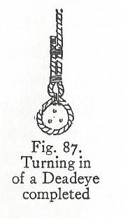
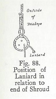
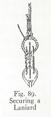
Hi Chuck, Here is how to serve and set up your shrouds and deadeyes. Strop and attach your lower deadeyes to the channel. The channel is the platform that sticks out from the side of the ship. Depending on which ship and when it was built will determine the shape and style of the chains (the extensions of the strops that secure the deadeyes to the hull). Measure the distance from the masthead to where the upper deadeyes will be. The distance, or drift between the deadeyes was usually about 2 times the diameter of the deadeye. Now double your measurement. The shrouds are going to be put on in pairs. Do not cut to the final length yet. You need to leave extra length for setting up the shrouds. Now serve the middle 1/3 of each shroud, calculated from your doubled measurement above. This will be the portion that forms the loop around the masthead. If you have calculated the length of the service correctly it should end slightly below the point where the futtock shrouds meet at the futtock stave. The forwardmost shroud on each side of the mast was usually served its entire length to prevent chafe from the sails and their gear. Middle the shroud pair around the mast head and clap on a seizing to form the loop around the mast head. The seizing should come just below the bolster on the trestle trees (the bolster is a quarter round molding placed next to the mast on top of the lattice of beams that supports the top platform. It's purpose was to ease the angle for the shrouds passing over the trestle tree. For each succeeding pair the seizing should lie just below the previous one. This would prevent the seizings from chafing against each other. Next, turn the upper deadeyes into the ends of the shrouds. Some find it helpful to make a jig that will position the deadeye at the proper spacing. The shrouds go around the deadeyes in a specific way that is determined by the lay of the rope. Looking from the outside of the ship, if you are using right hand laid rope the shroud will pass counter-clockwise around the deadeye, behind the standing part (that is to say more inboard) and then the end is seized to the standing part with three seizings. For left-hand laid rope the shroud runs the opposite, clockwise around the deadeye. The first seizing to be put on is called a throat seizing and it is put on where the two parts of the shroud cross above the deadeye. The next, the middle seizing, is a short distance up the shroud and the third, the end seizing, an equal distance above that. The rope that runs between the upper and lower deadeye is called the laniard. The laniard should be a bit less that half the diameter of the shrouds. It always starts on the upper deadeye in the hole furthest away from the end of the shroud. The stopper knot will be on the inboard side of the deadeye. Pass the laniard from outboard in through the corresponding hole in the lower deadeye then up and from inboard out through the middle hole in the upper. Continue passing the laniard through the remainig holes. You will end up with the laniard passing from outboard in through the last hole in the lower deadeye. The end of the laniard is then hitched around the shrouds where they cross above the deadeye. It is best to leave some extra length on the shrouds and laniards so that final adjustments can be made later in the rigging. Set up the shroud pairs starting with the forward most and alternate sides until all of the shroud pairs are done. If you have an odd number of shrouds on each side the final one will go on single. I hope that helps, . Regards,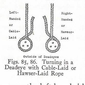
-
If you consider that each rope on a ship is either being hauled on or slacked off to accomplish some task you will quickly see that there needs to be some length on the hauling end of the rope that will need to be coiled on the belaying pin. Take for example a halyard. With the yard in the lowered position the blocks for the halyard tackle are at their farthest apart. There is a certain amount of rope that makes up this tackle. As the yard is hoisted by hauling on the tackle fall these blocks get closer together and all of that rope that used to be in between the blocks is now in your hands at the working end. That is the rope that must be coiled and hung on the belaying pin. All of the lines on the ship function this way. So, there will almost always be a coil of line to be found at the working end. Regards,
- 3 replies
-
- 13
-
-
The angle of the ladder varied with the amount of room available. No standard angle as far as I can tell.
-
Sails size ? Need advice for more realistic sails
popeye2sea replied to ioanniz's topic in Masting, rigging and sails
It appears that the sail from the kit and the sail from the book are from two different ships. You have to decide which is more correct. Since the proportions of the sail are determined by the length of the yards, and you already have the kit yards, I would just go with your existing yards and make your sails accordingly. Unless, of course, you decide that the yard lengths depicted in the book are the correct ones. Regards, -
That is a common misconception. The average height of a human has not changed much in hundreds of years. They just leaned out of the gun ports sometimes to service the guns. Or they used thick rope for the handles of the sponge and rammer. Made for a flexible handle that would bend around corners.
-
I seem to remember a reference that stated the drift between the upper and lower deadeyes should be 1.5 to 2 times the diameter of the deadeye. I do not remember where I read this though. Regards,
-
Of course, you still need men aloft shaking out the sails. As soon as the anchor is aweigh the vessel is adrift, so you need to set sails for her to be hove to while you finish raising the anchor.
-
I think we can assume that working the capstan to haul the ship up till the anchor cable is 'up and down' (the actual term we used to use in the Navy) and then weighing and hoisting the anchor out of the water would take the longest. The stowage of the cable in the cable tier would run concurrent with this. The set up, i.e.: Laying out the messenger, breaking down stanchions, and rigging the fish davits would not take that long. I could see catting, fishing , and stowing the anchor taking , timewise, something in between the two. I bet I could find more info if I spent more time researching.