
.JPG.ca33079f5815b861e67b9c2cccd37982.JPG)

Blue Ensign
-
Posts
4,281 -
Joined
-
Last visited
Content Type
Profiles
Forums
Gallery
Events
Posts posted by Blue Ensign
-
-
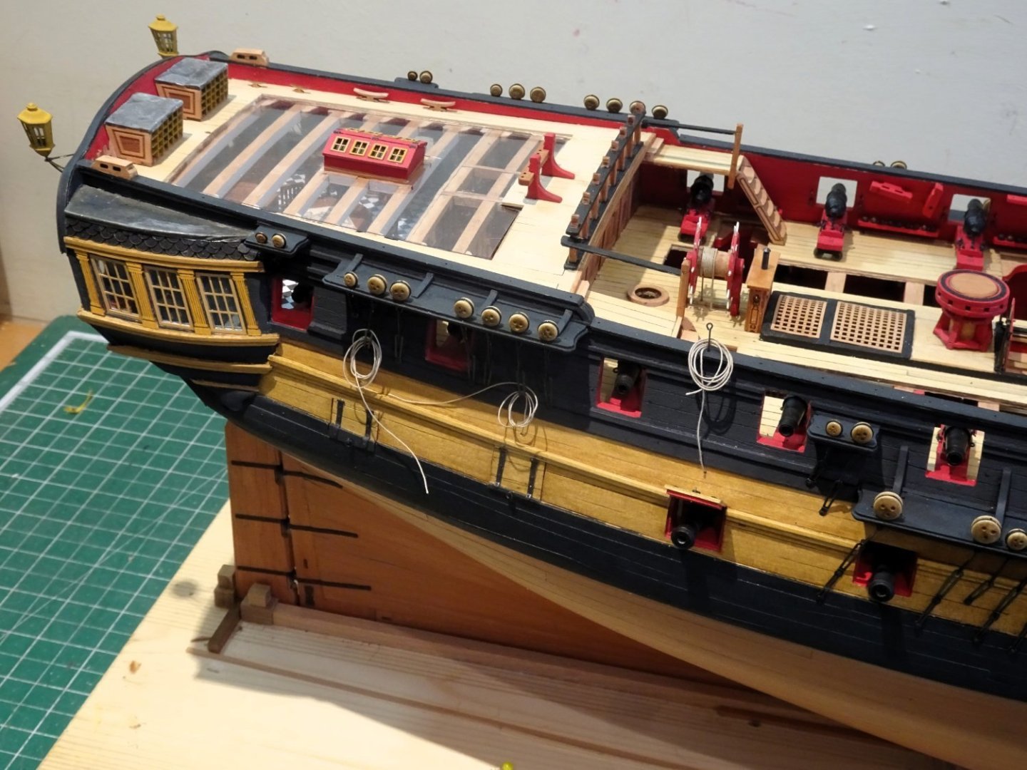
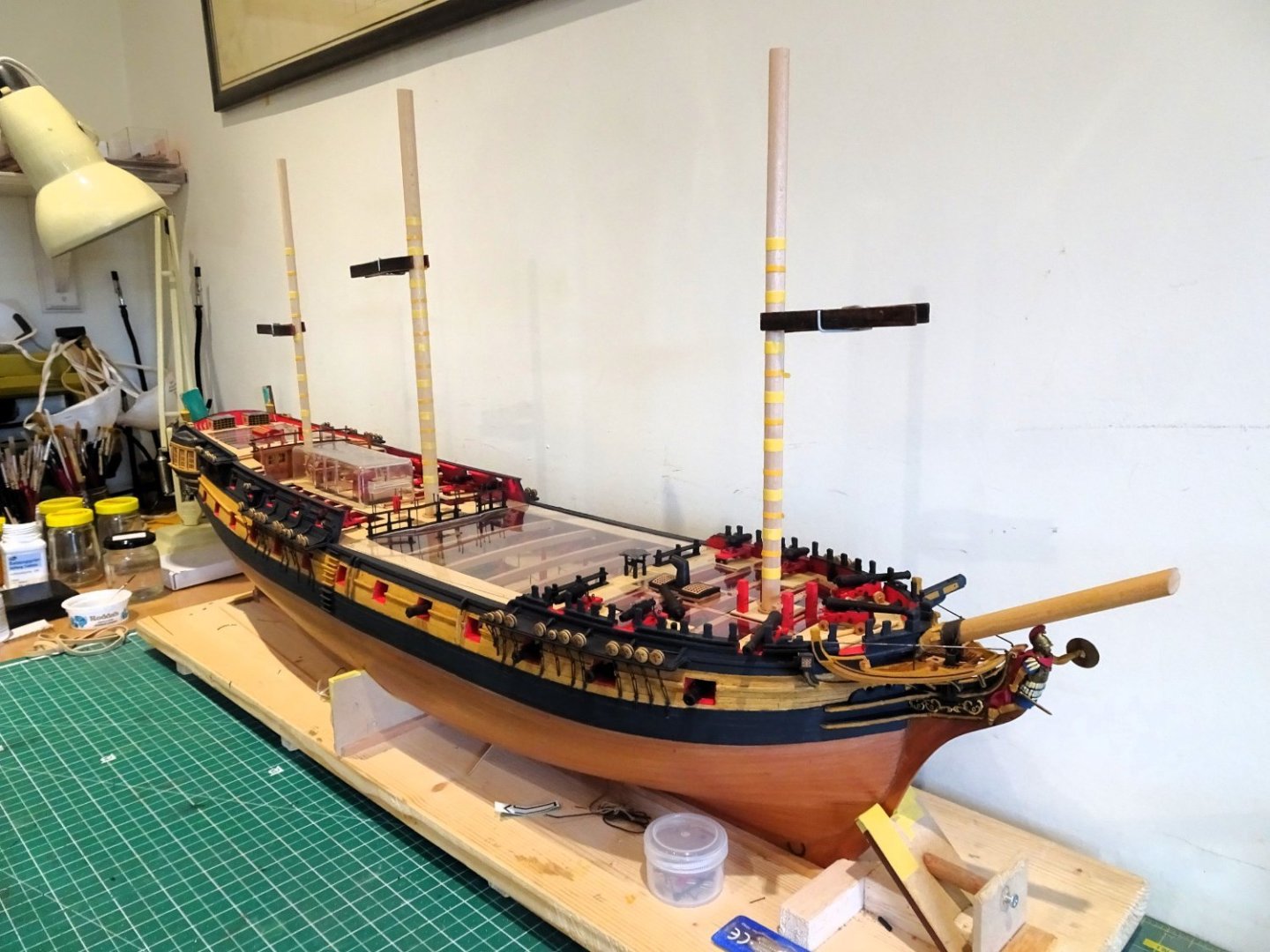
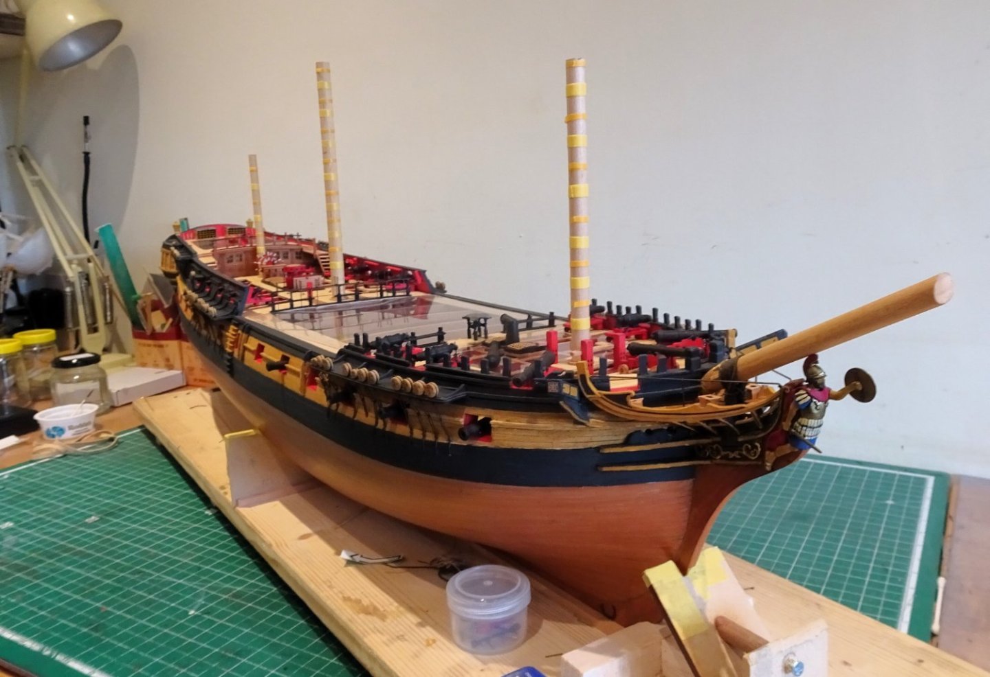
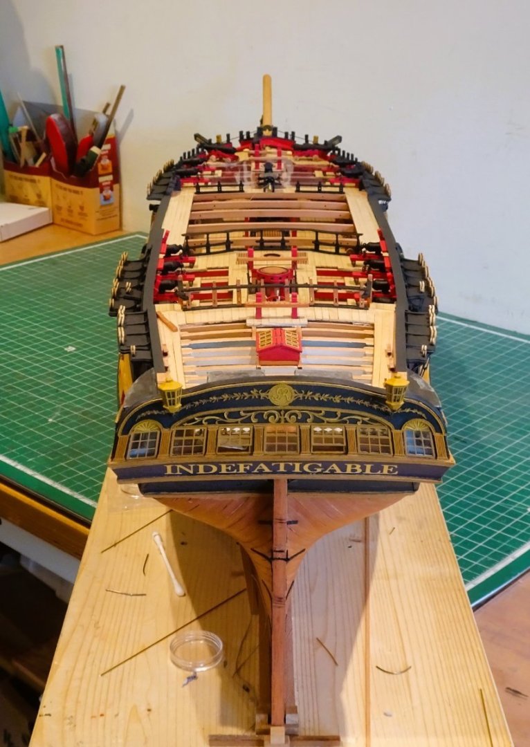
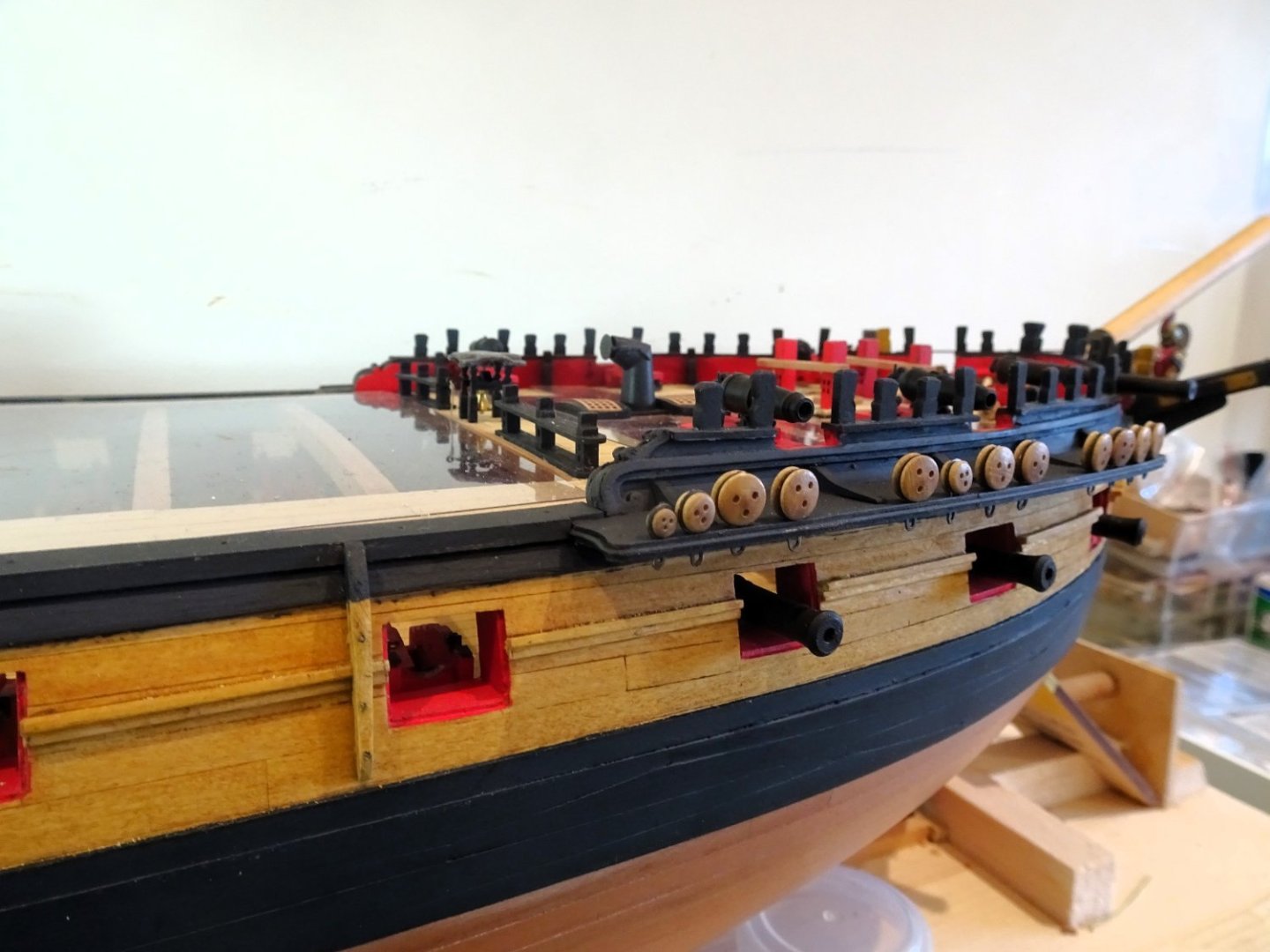
Post One Hundred and fifty
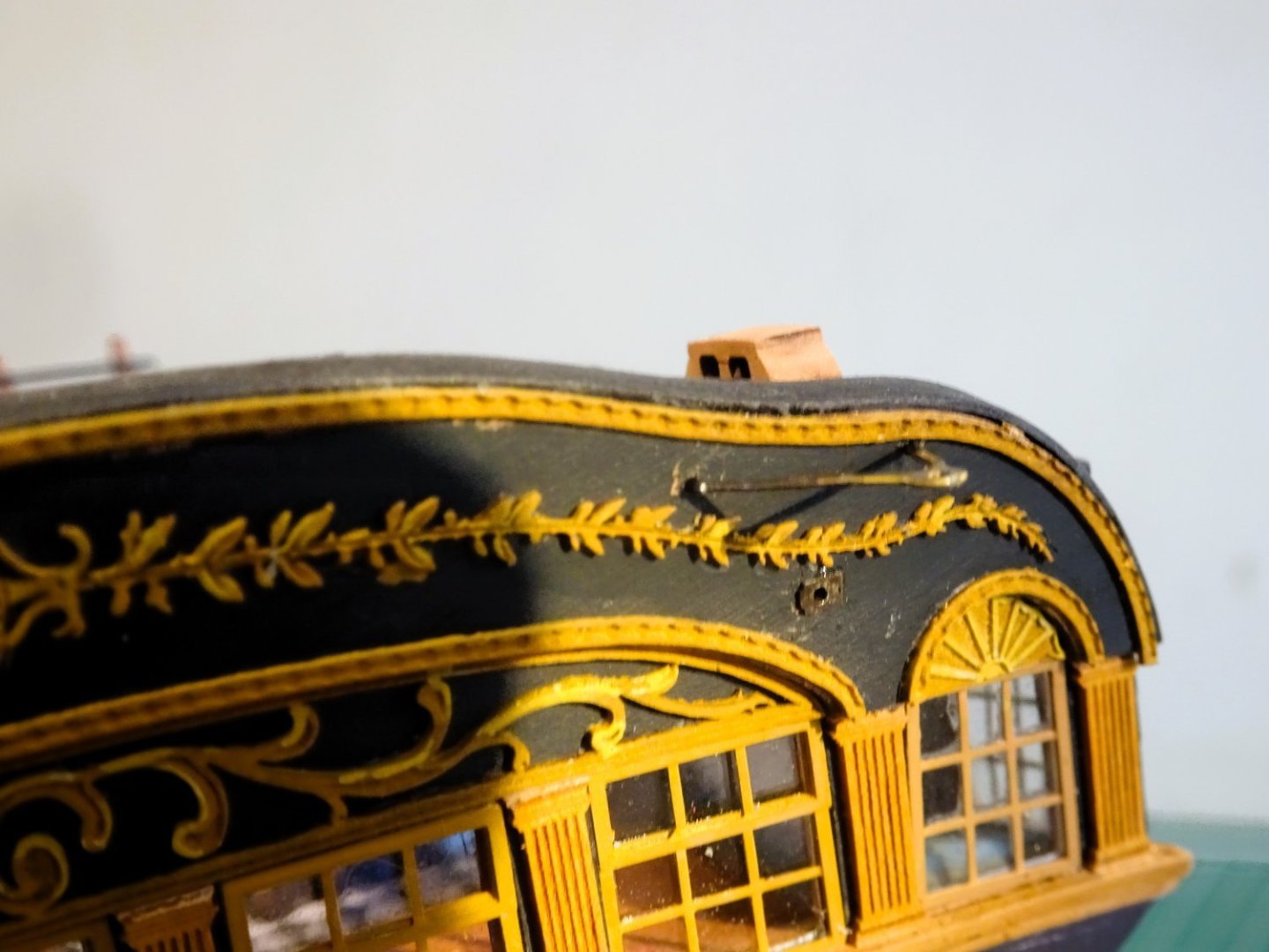
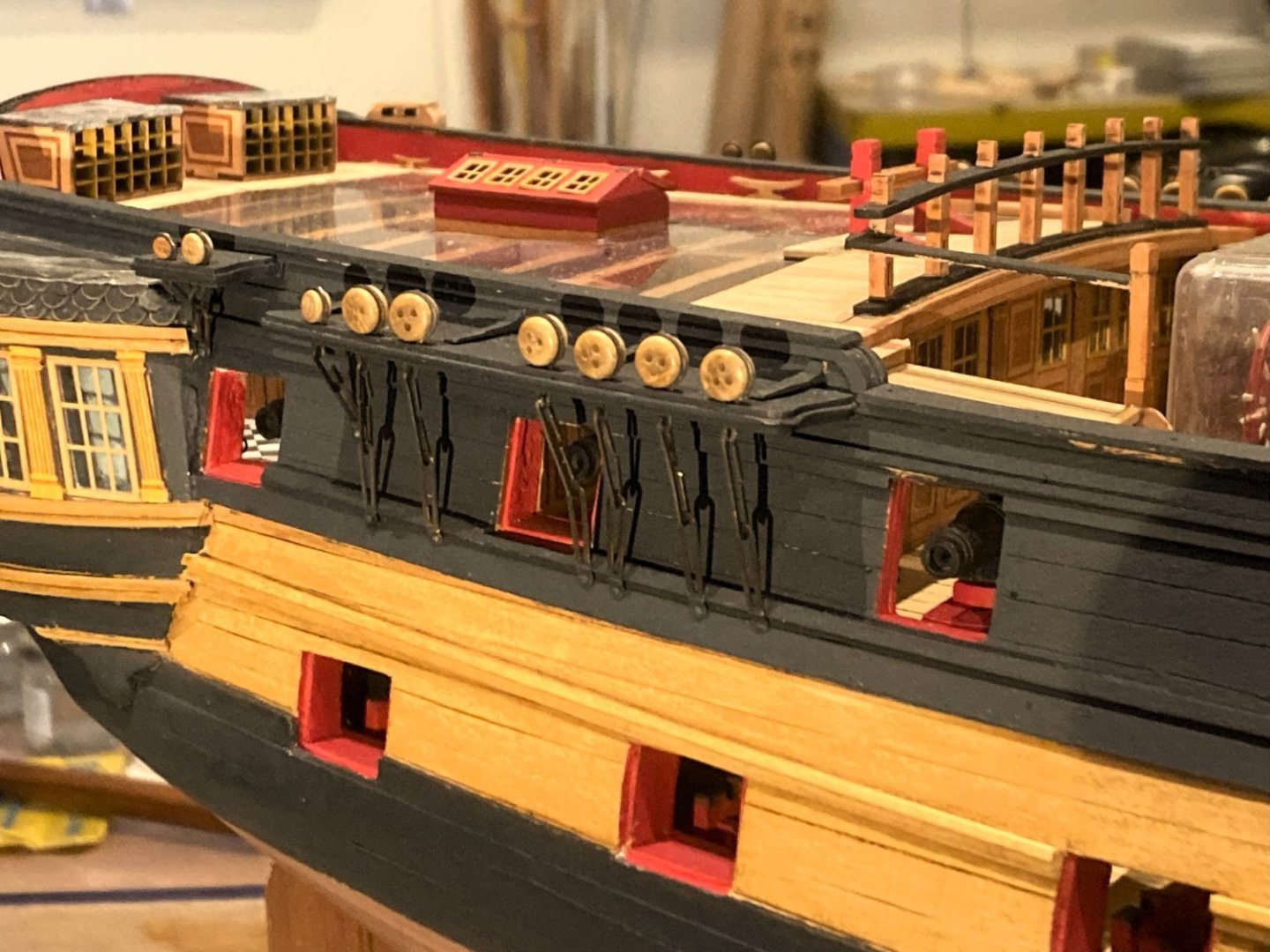
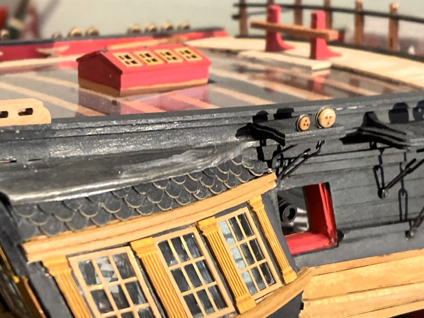
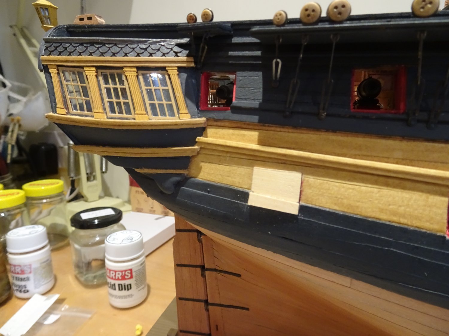
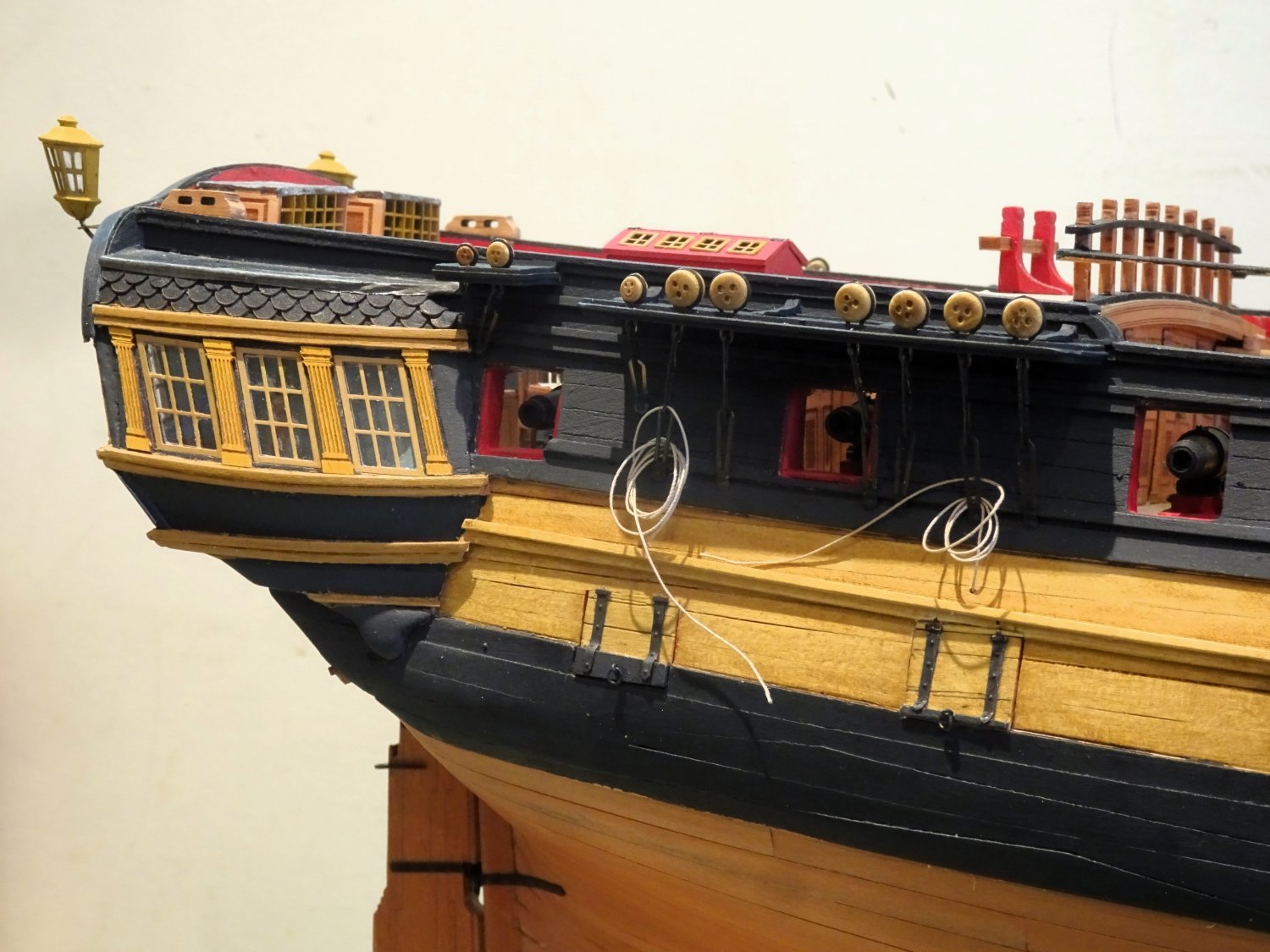
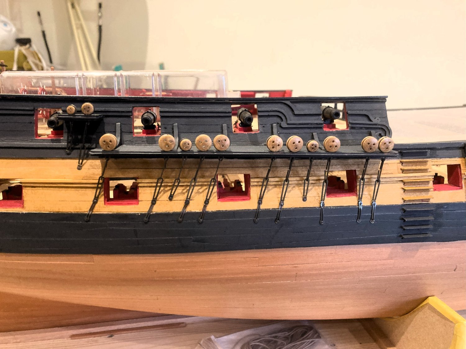
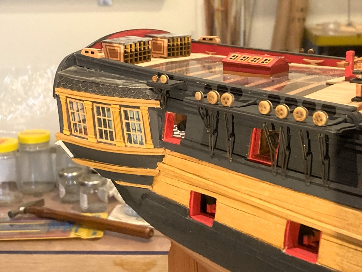
Completing the ports
The two enclosed Qtr deck ports remained to be done.
Usual top hinged lids into the Great cabin, and a pair of side opening doors into the Coach and Bed space.
3660
I thought I had done with queries about ports, but I’m not entirely convinced why side opening doors are shown in the position they are, constrained by Mizen chains which only allow them to open half way.
They are a feature usually found in positions above the channels, or at the foremost bow port, where space is restricted.
2231
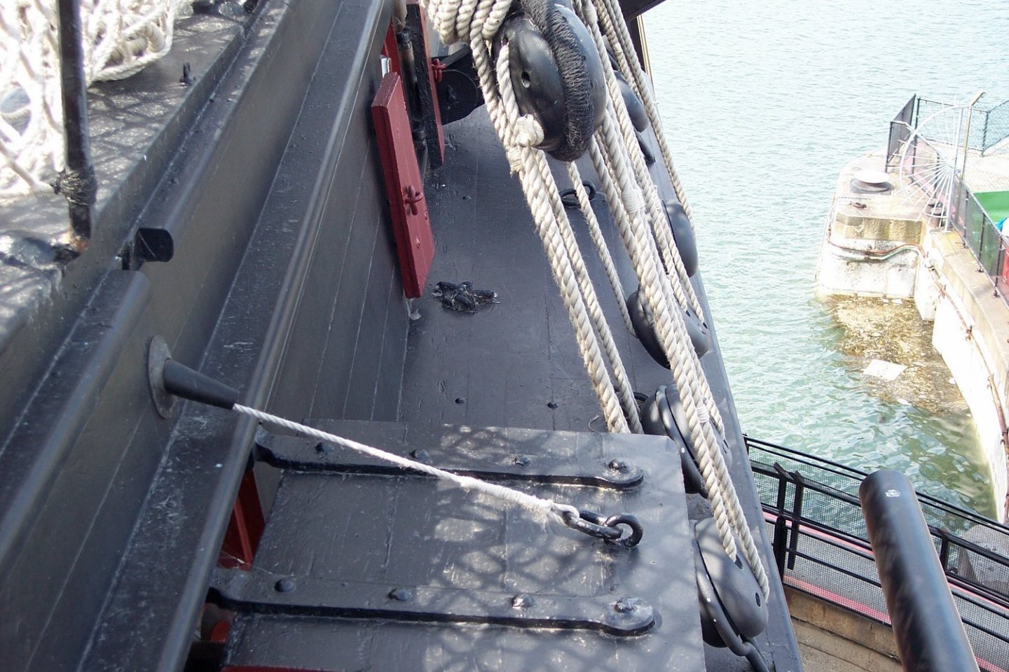
This shot onboard Victory taken when I blagged my way onto the Poop deck shows similar doors in place.
The photo also has other interesting features. Note the tube thro’ which the port lid lanyard goes inboard, and that the port only has one lanyard presumably due it being of lightweight construction over a Qtr deck cabin.
The final interesting feature for detail fans is the knot secured on the Mizen channel.
This is the reason at the time I wanted to look over the Poop.
The knot secures the Rudder pendant which attaches to the chains and is used to control the rudder should the tiller lines be shot away.
Back to INDY..
Notwithstanding the above, the side doors do make a nice feature and provide additional interest to the build, more so if displayed closed.

1901a
I used a normal port lid as it makes more sense to me.
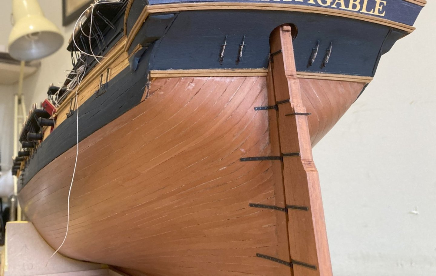
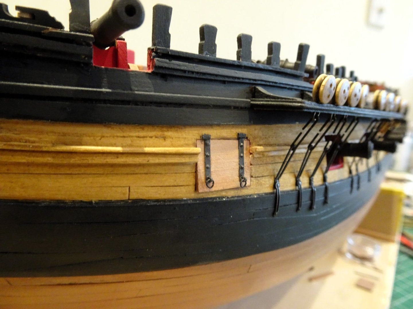
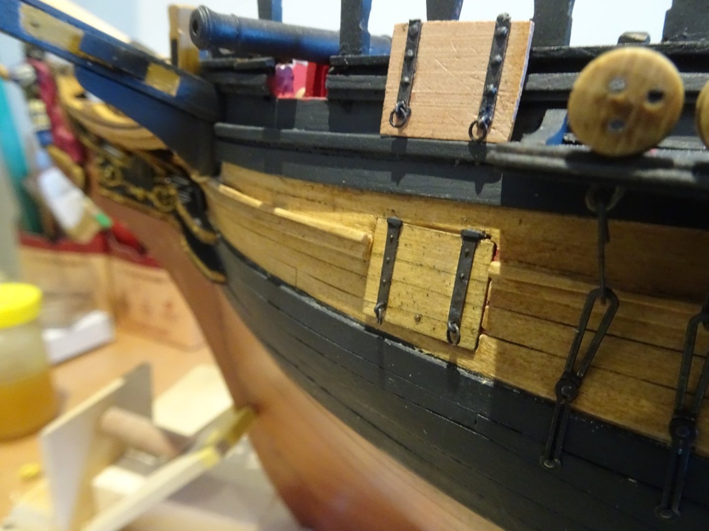
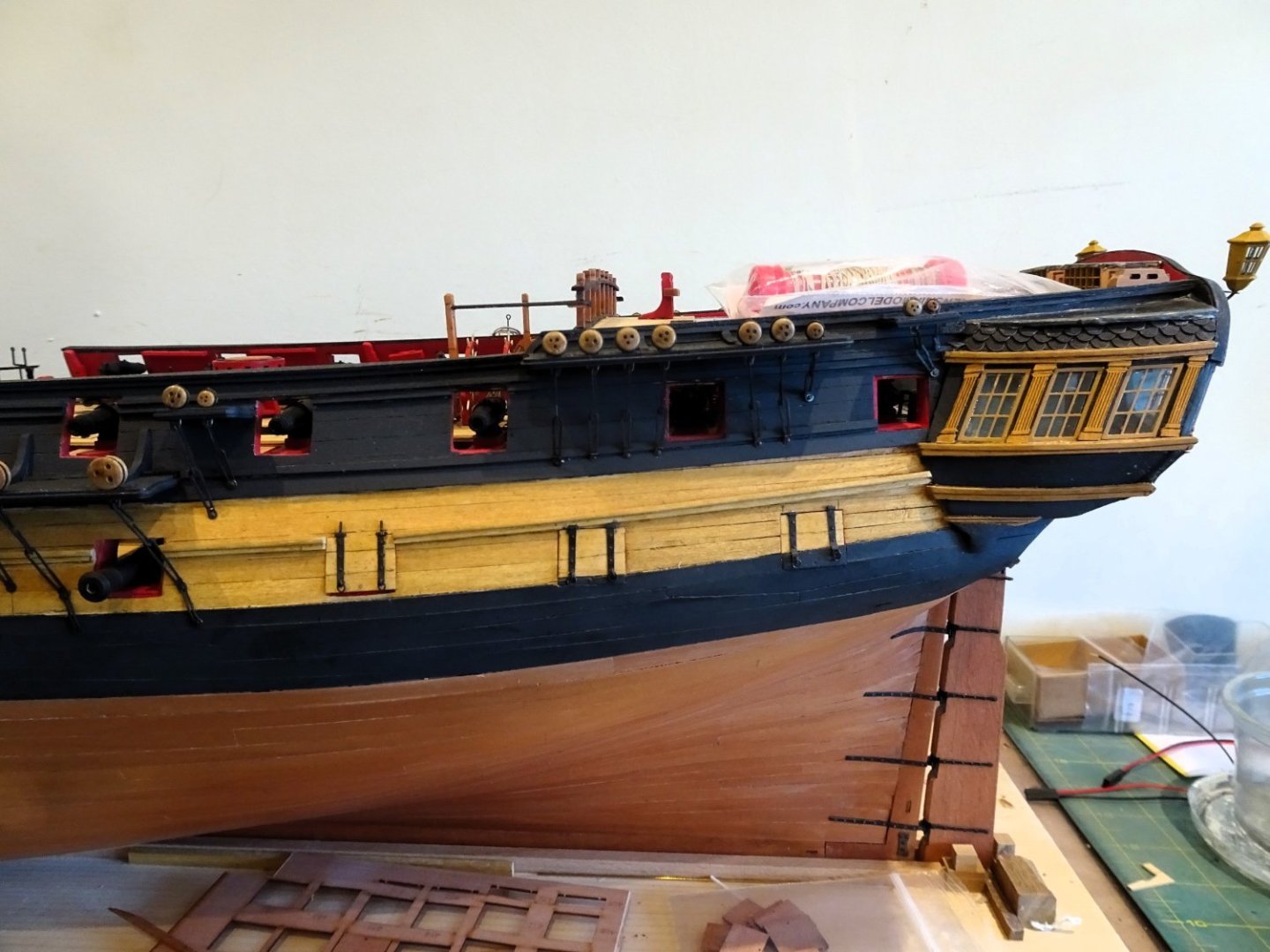
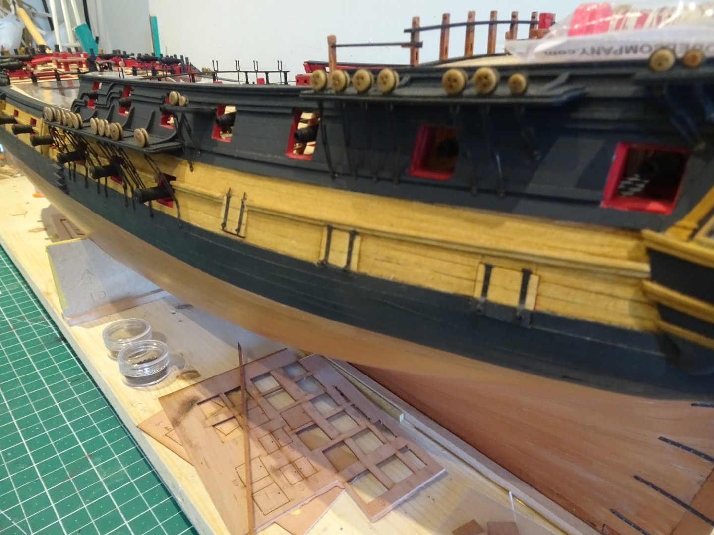
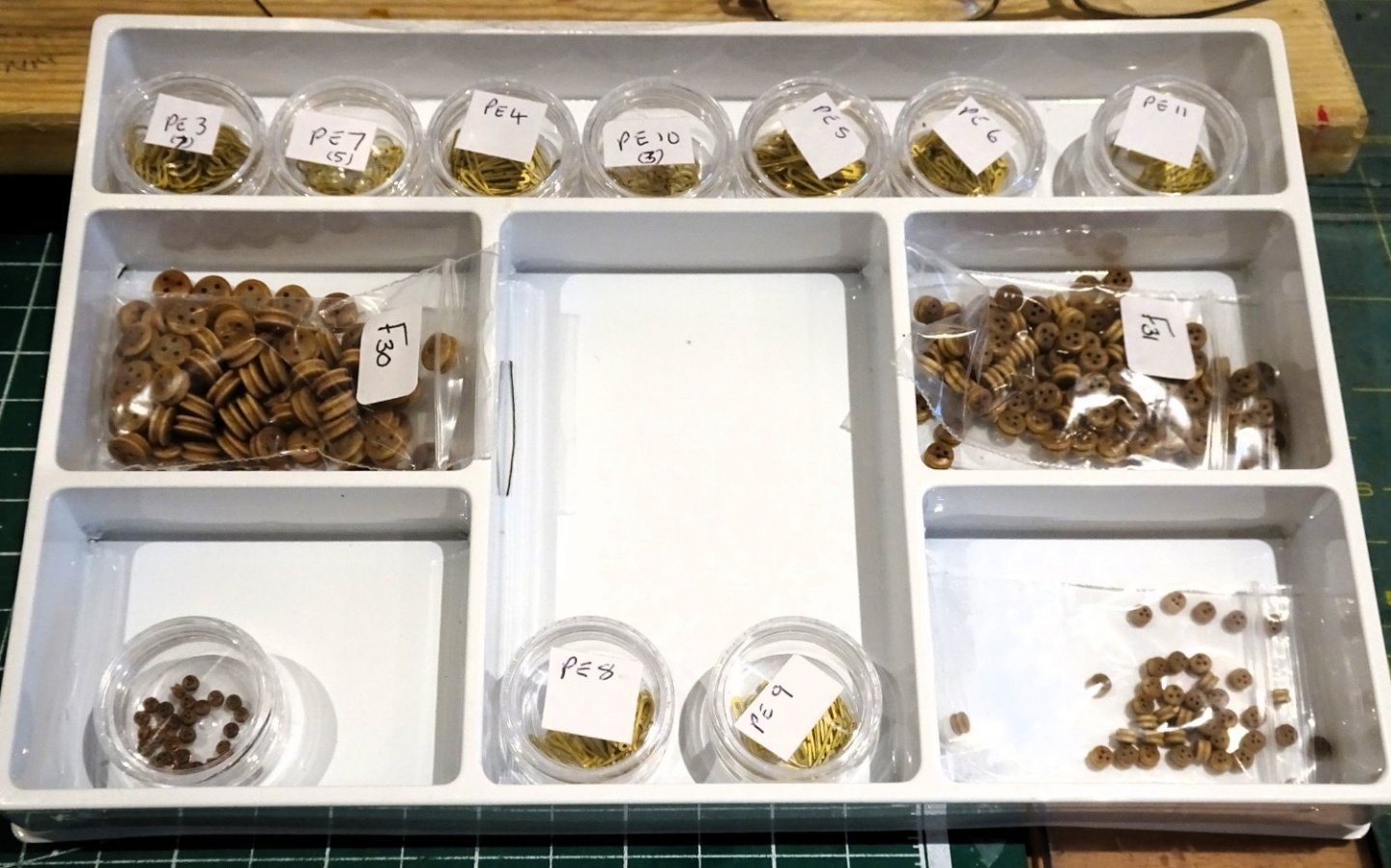
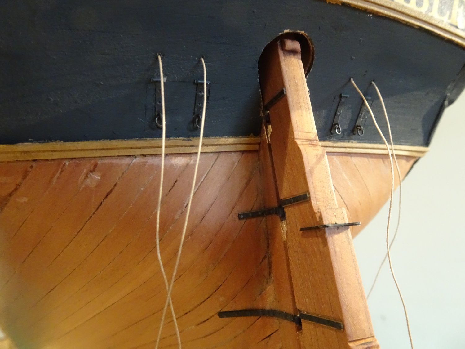
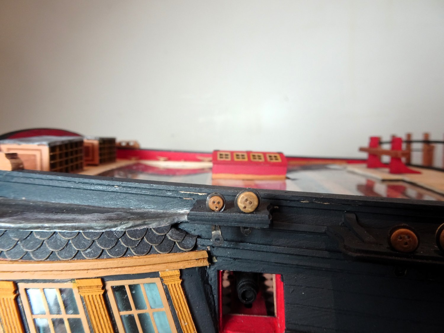
Stern Ports
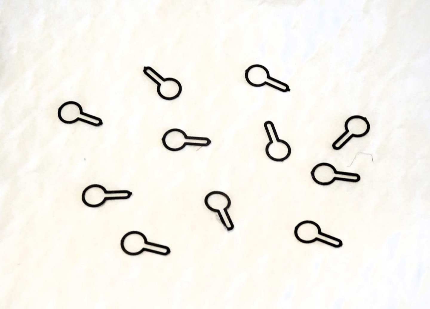
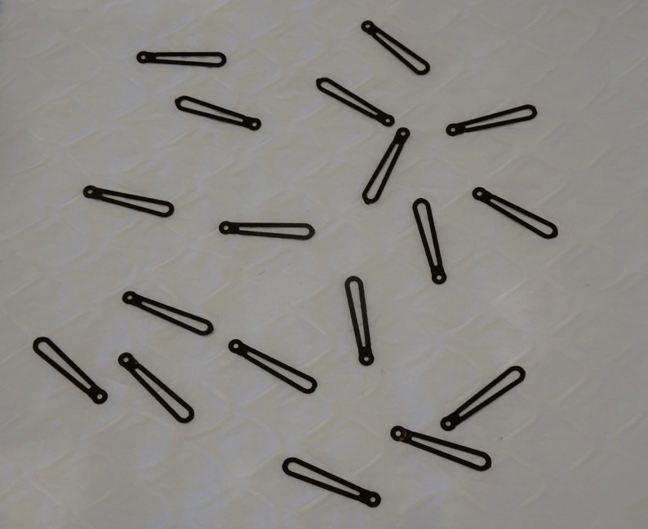
There are two stern ports engraved on the lower counter, the plans show use of provided hinges (PE47) over the patterns, but I didn’t seem to have sufficient to do this, but the Laser board Syren straps filled in nicely.
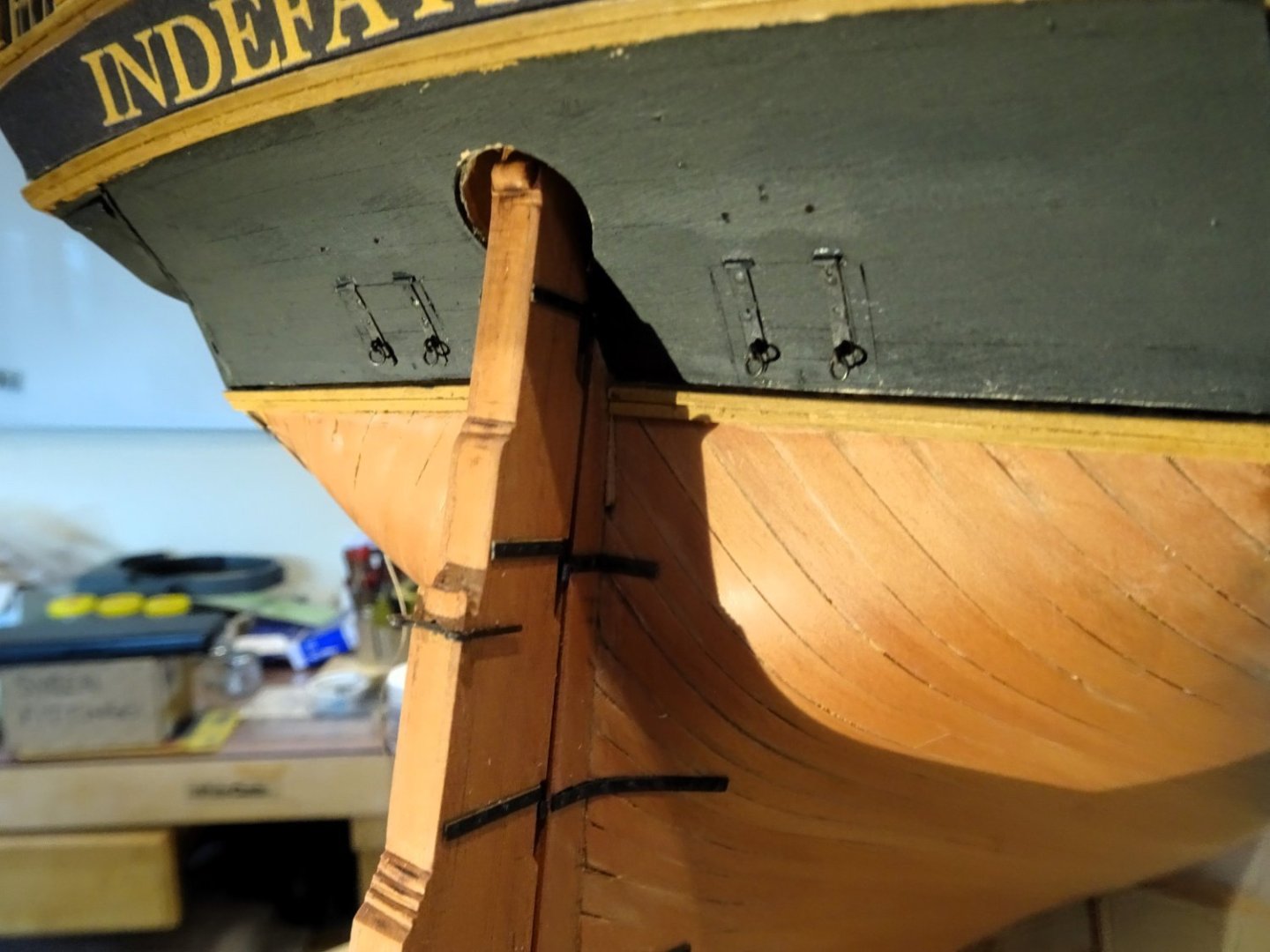
3794
This is not a very prominent area of the model but that is no reason not to enhance it.
 3796
3796
Addition of double lift rings and lanyards complete the effect.
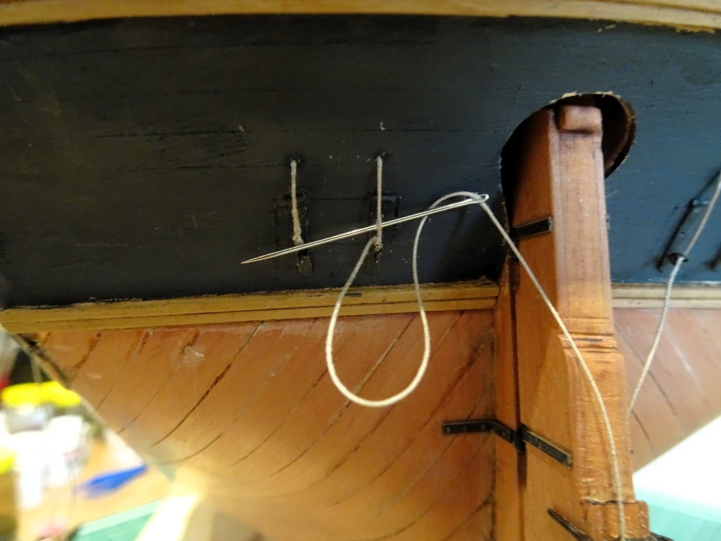
3800
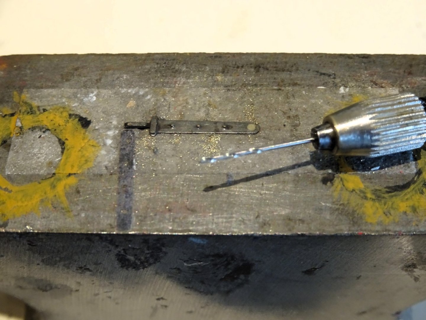
The trickiest part is securing the lanyards thro’ the lifting rings using a false splice.
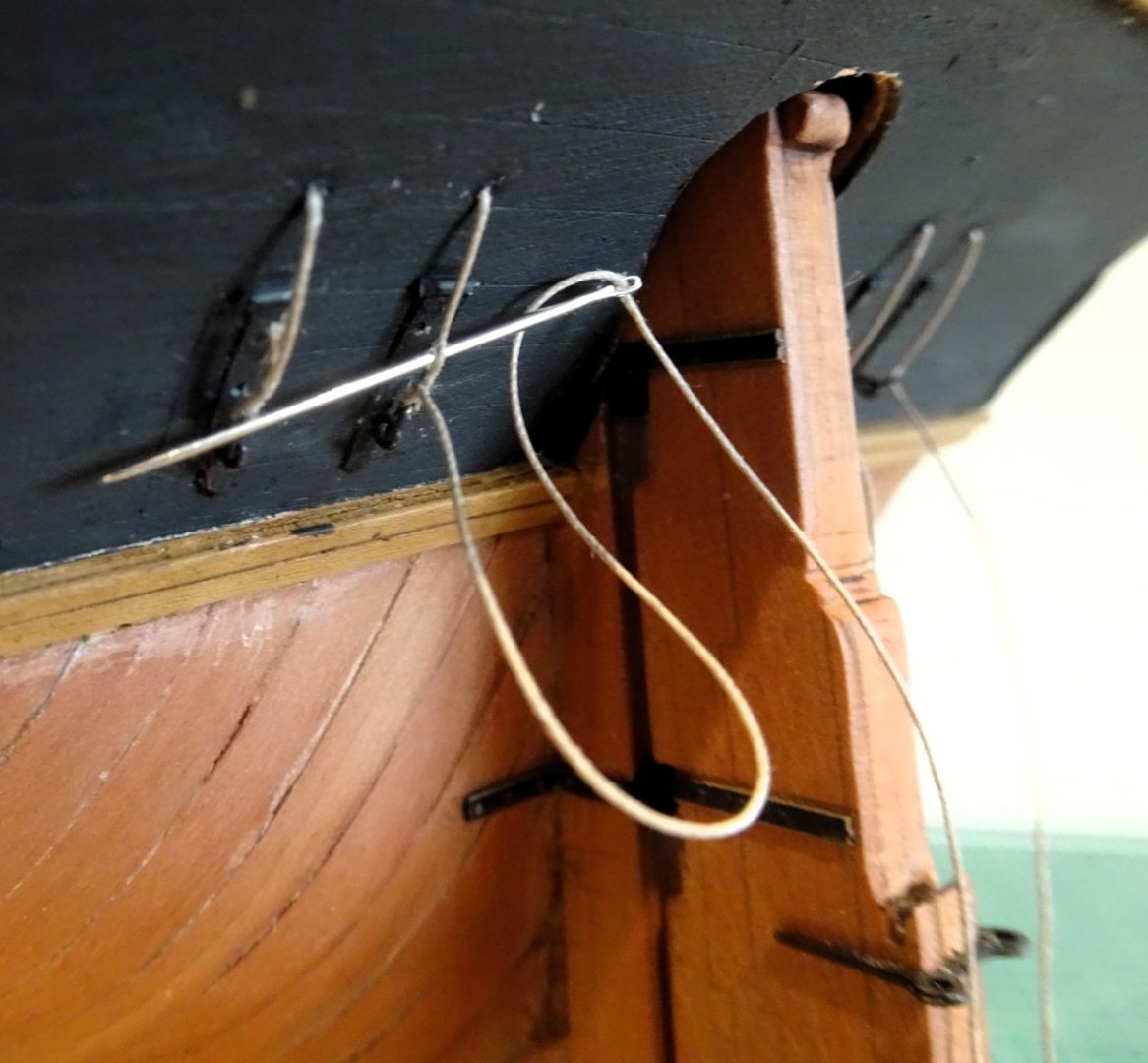
3799
Getting the needle thro’ the 0.3mm line is a severe test of my aging eyesight.
1900a
Still lot to do on this build.
B.E.
26/02/2024
- Glenn-UK, CiscoH, Theodosius and 27 others
-
 30
30
-
Chuck produces a lot of stuff useful to non Syren kits builders, and I see he now has working port lid hinges (Winchelsea) which may adapt to smaller scales.
His Laser board rudder /pintle sets are my go to for use on the Vanguard kits I have built recently, and easily double for lid hinges.
For 'Indy' Chris has supplied laser board straps for the Rudder, for me, brass etched rudder straps are a thing of the past.
B.E.
- mtaylor and hollowneck
-
2
-
-
-
Thank you Ron, and Allan for your input.
3787
Chris has done a great job on designing and producing the strops/chain link combinations to allow the fitting of these with the minimum of fuss, and with an excellent result.
3789
The trade-off is that the middle link chains of necessity have a tiny gap that is necessary for linking the strops to the lower chains and is a simplification much appreciated.
The middle links should retain that elongated oval shape and personally I don’t think they are improved by either turning them into effectively an iron strap with eyes either end, or trying to squeeze the gap together that risks deforming that perfect oval shape.
David Antcherl does indeed cover the making of chains from scratch very well, but in this case, and at this scale, even my inner pedant recognises that rejigging the chains is simply not worth the effort of messing with Chris’s excellent set-up.
B.E.
- Theodosius, KARAVOKIRIS, allanyed and 8 others
-
11
-
Post One Hundred and forty-nine
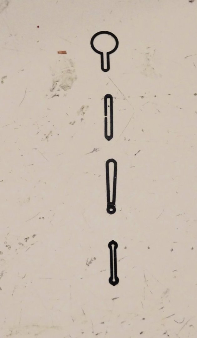
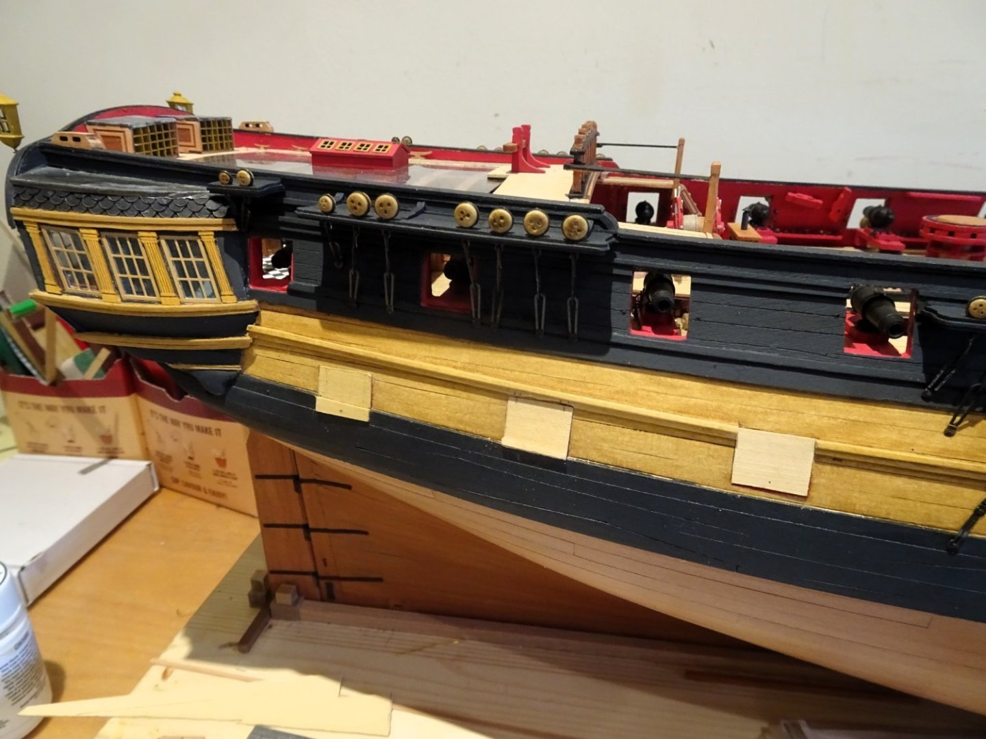
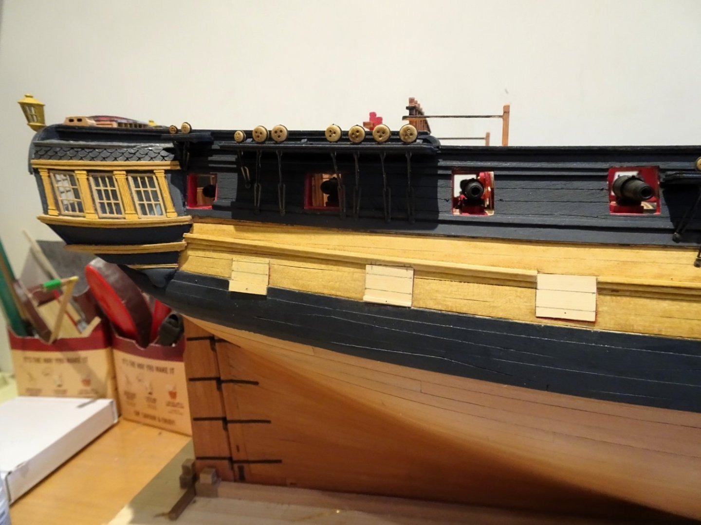
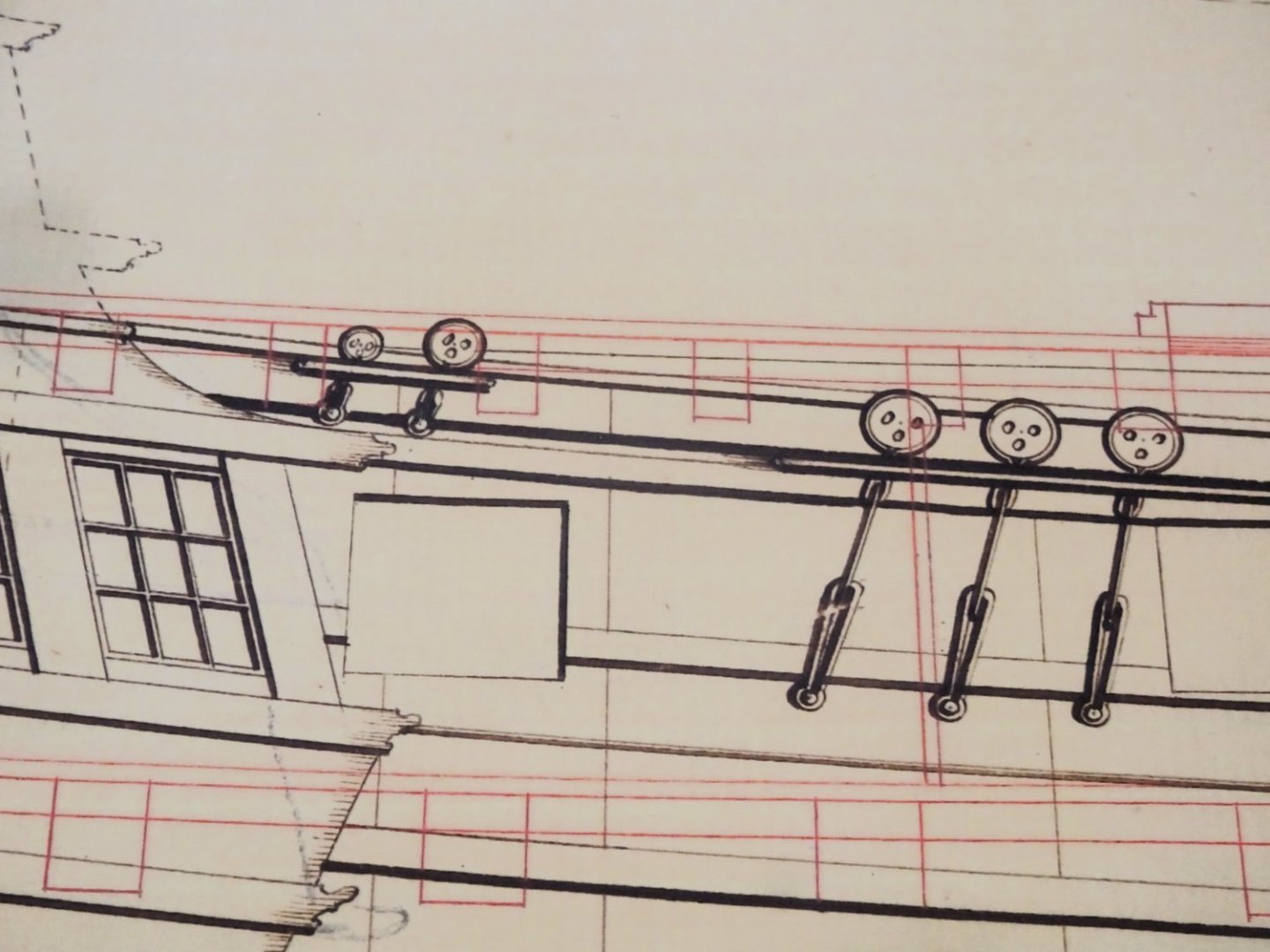
Thinking more about Gunport lid fittings
Before I start the gunport fixing on the Starboard side, my mind keeps returning to those single lanyard fittings.
The provided port lids look pretty enough and the brass etch versions provide an easy fixing to the hull with the combined hinge, port stop and flexible tangs for fixing the lid to the hull in the open position.
However, I do like to make changes to enhance historical accuracy where I can, and I think Indy should really have double lanyards.
On a model the size of Indy, particularly Navy board style, such detail gains more prominence, not having all the top hamper to distract the eye.
3763
Revision One
I have mocked up a revised port using a spare port lid.
I am using Syren laser board rudder straps, cut to size to act as the hinge straps.
These conveniently have nail holes pre-drilled, the bottom one is drilled thro’ to take the ring bolts for the lanyards.
The tricky part is representing the port hooks that secure the hinge.
For the purposes of my exercise, I have used separate tiny segments of Boxwood.
The final touch is to add spots of pva to represent the bolt heads.
This would work for closed ports but for open ports wire would need to be inserted in the top edge to replace the tangs on the kit version.
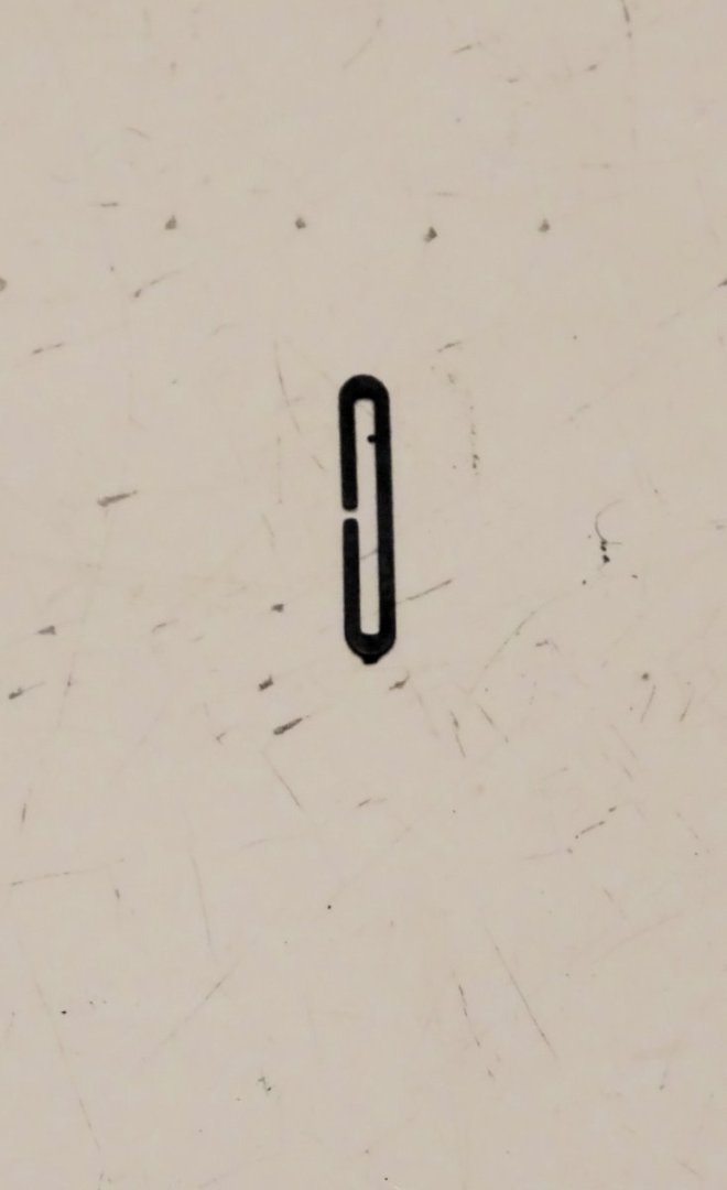
Revision Two
I had abandoned an early attempt to drill thro’ the bottom bolt head of the kit hinge due to broken bits.
I resolved to try again.
I filed the bolt head flat and started the hole with an awl. This time I was able to drill thro’ using a 0.6mm drill in a pin vise without breaking the bit.
3772
I secured the hinge to my mini anvil using double sided tape.
The ideal solution would be if the hinges could be pre-drilled during manufacture.
3780
Modified hinge straps on the Fore port. The example above it is the laser board version.
3781
The forward of the three port lids will be displayed open.
3782
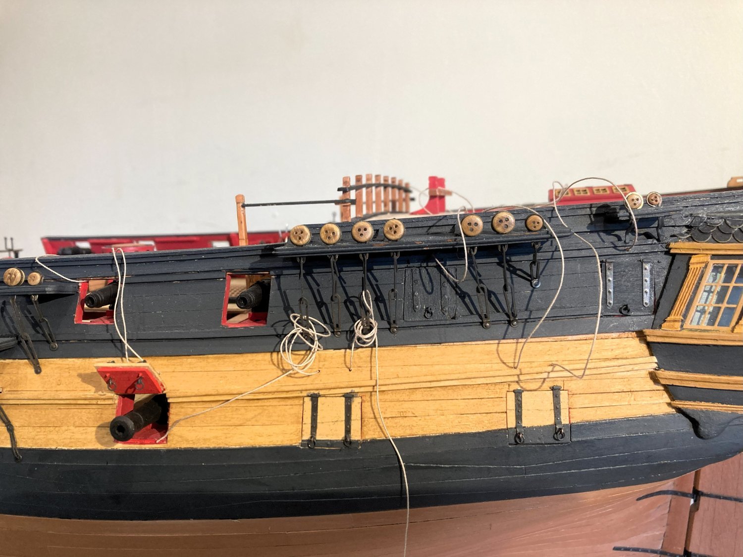
So, the starboard side ports are fitted with correct double lanyard fixings, and the Port side for a central single lanyard.

3748
Perversely, I think the single lanyard arrangement has a better aesthetic.
One last thought on gunport lids:
The second and third ports from the bow, adjacent to the Galley, are without lids. These ports lie beneath the Fore Channels.

3784
This is a tricky area, some contemporary models have them some don’t.
Logical thinking would support the fitting of lids for those adjacent to the Galley Stove. One big wave and out goes the stove fire that the cook has spent some time getting up to heat, but I don't think they lit the stove in very severe weather..
I note that Alex M’s drawings for his Anson razee do include lids in this area, and incidentally double lid lanyards.
The fitting of port lids in the open waist and Qtr deck areas was removed by Navy Board order dating from 1703.
Well, that little excursion has soaked up a day and a half,
...........time to move on.🙄
B.E.
24/02/2024
- mtaylor, BobG, Wintergreen and 16 others
-
19
-
Kit provided hoops at 1:64 scale are probably not feasible, but that doesn't mean they can't be added at that scale.
I use sub 1mm strips cut from a Manilla folder which fulfil the purpose very well.
They stick easily to the mast, conform to the shape around the cheeks and fish, and are the right colour.
B.E.
-
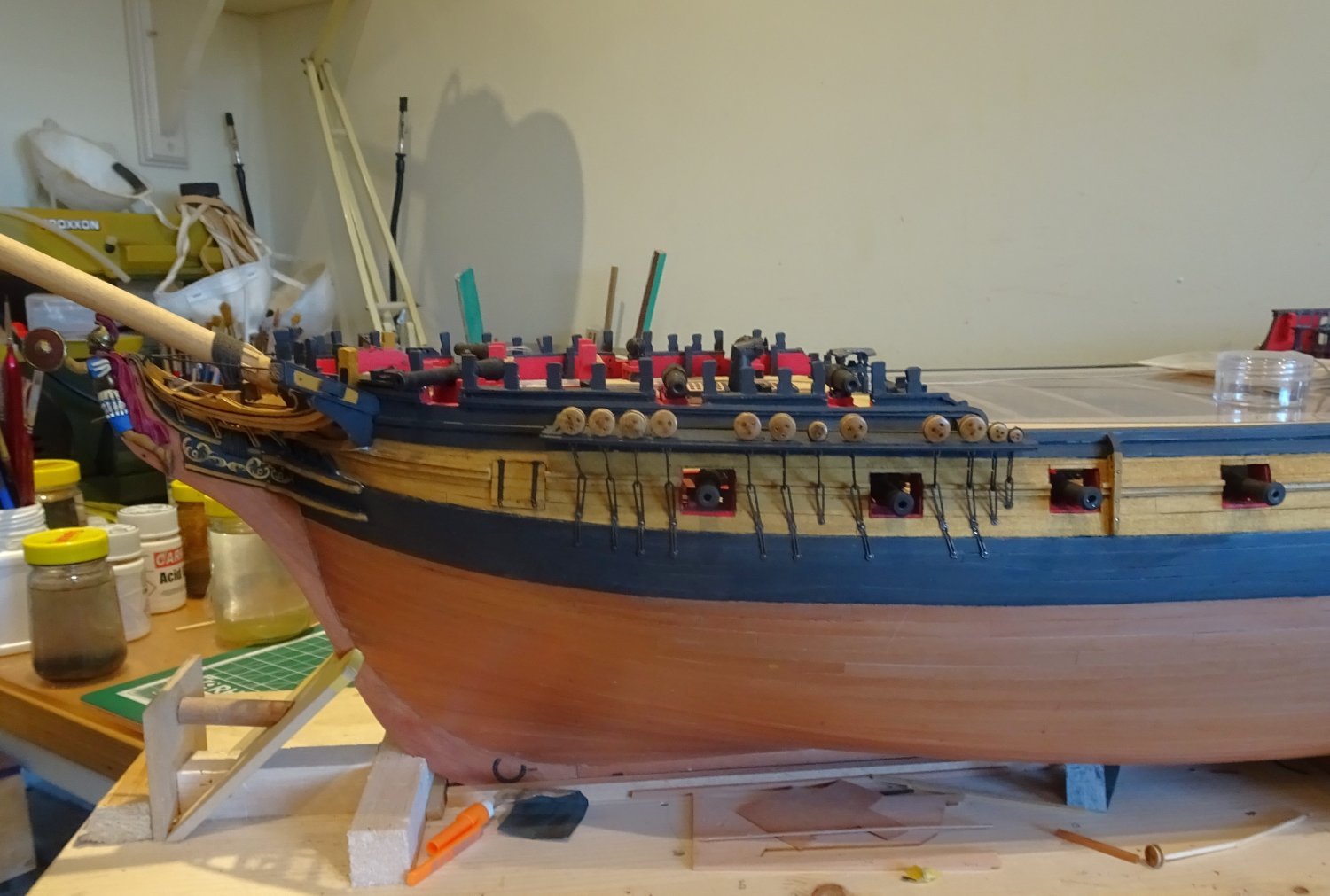
Post One Hundred and forty-eight
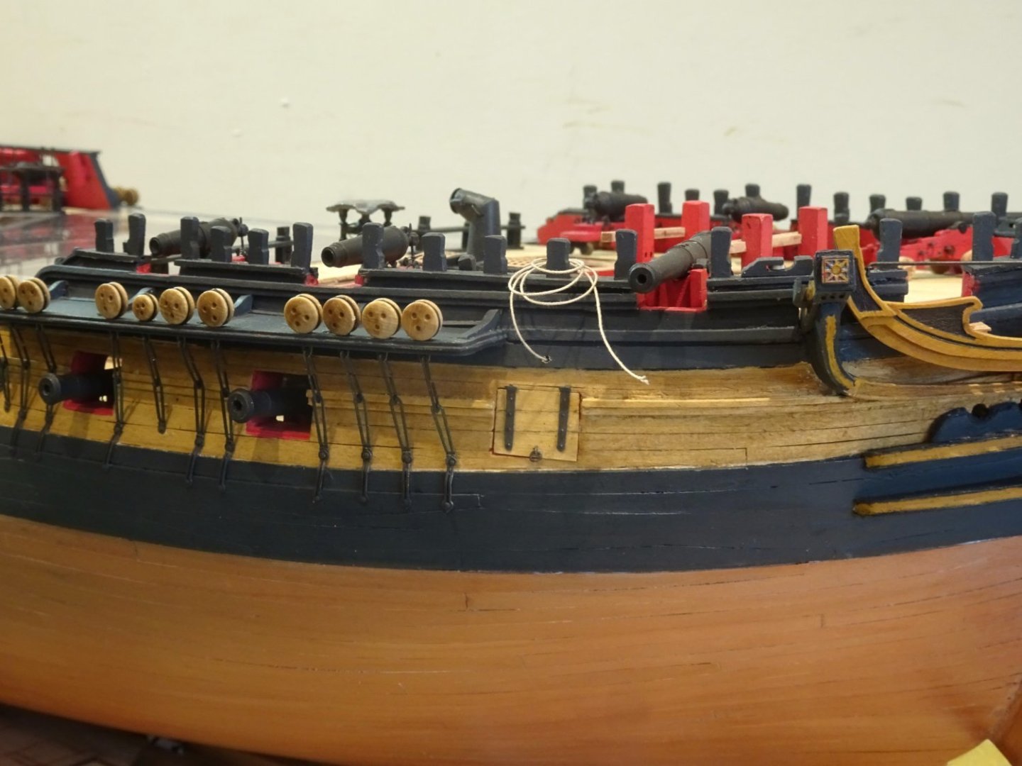
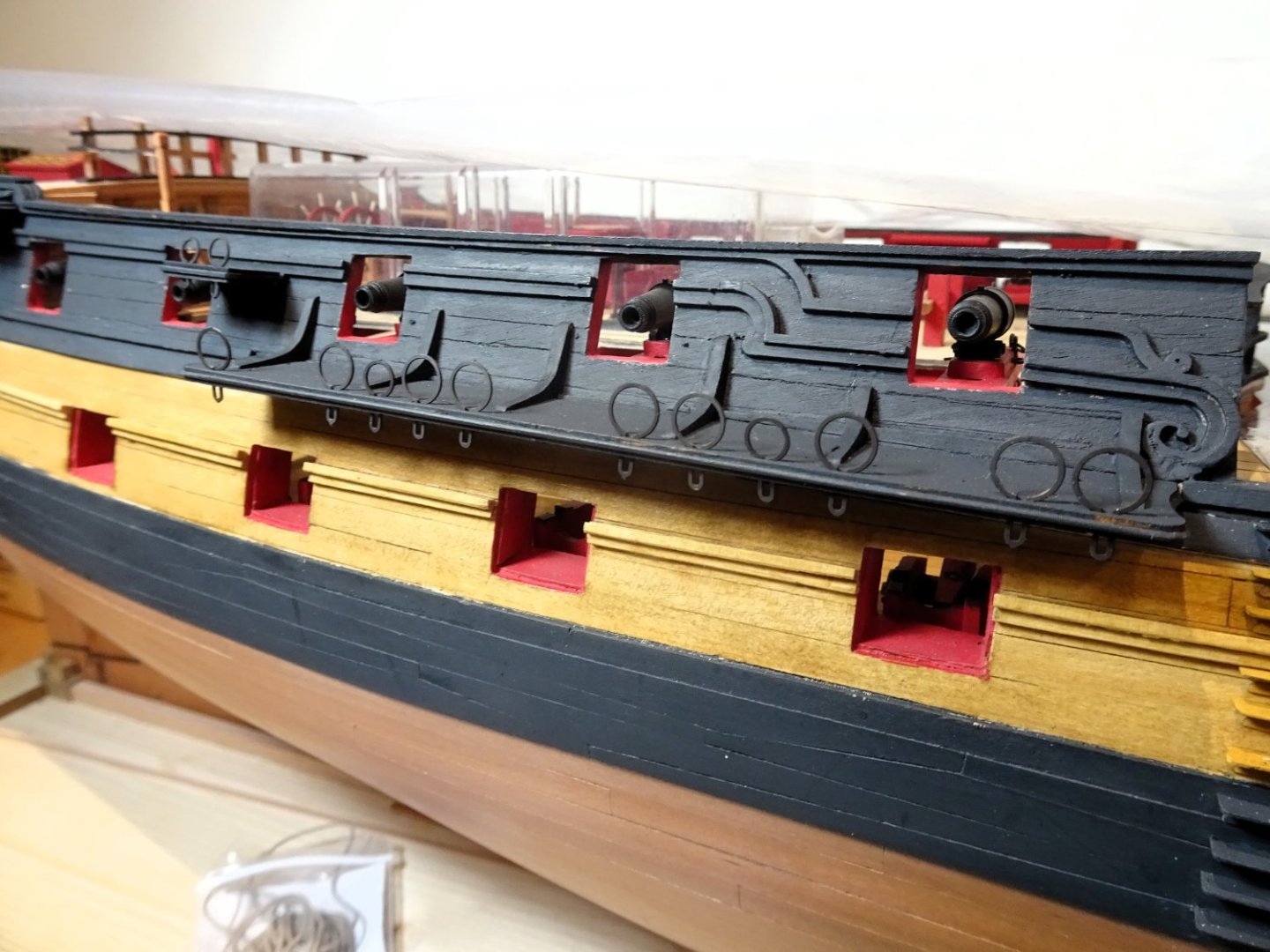
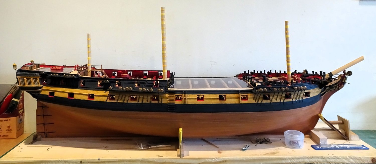
Fitting the Main ordnance
The design of the 24 pounder carriages is such that it allows the guns to be fitted much later in the build, to reduce the risk of knocking them out of position.
The carriages were pinned to the deck earlier, and the guns are slid thro’ the ports to locate the trunnions in the open cap squares.
Quite a snug fit and it helps to have the port line at eye level to do the job.

3731
For fixing I used ca on the trunnions and bent nosed tweezers to press them into position.
For the eight waist guns, with each fitting the model is rotated to check that the barrels are squarely located on the carriages.
For closed decks this aspect won’t be seen.
The simplification of the ‘open’ capsquares has no relevance because any view of them is severely limited, and the tops of the trunnions will masquerade as the capsquare tops.
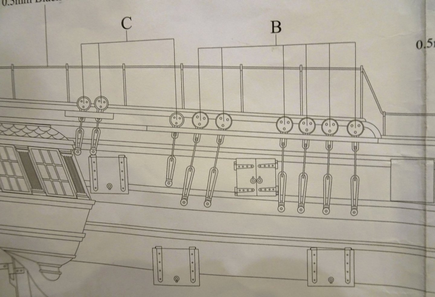
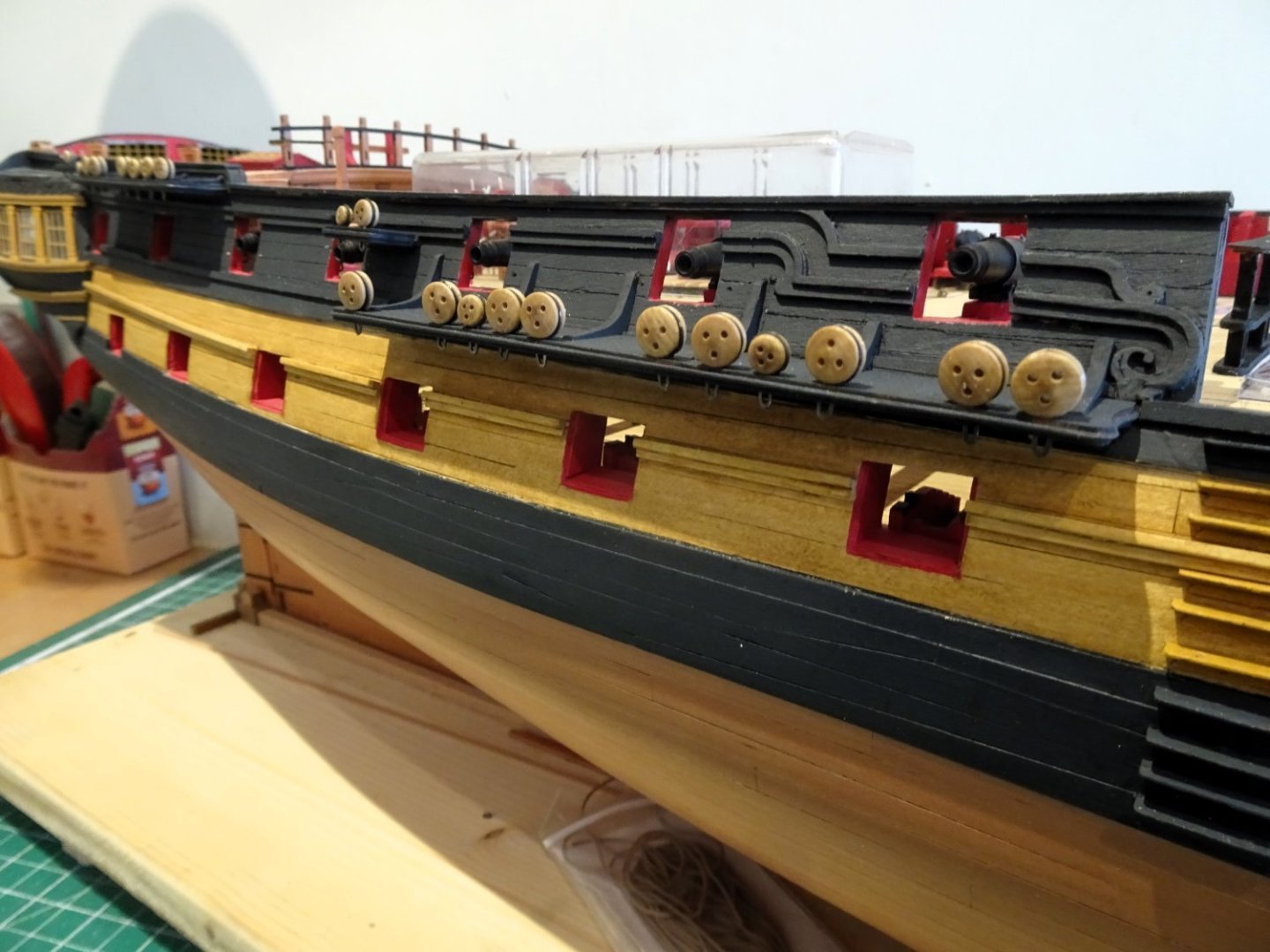
Port Lids
These are pre-cut in Pearwood and supplied with etch hinges.
For the Qtr deck and Bow port lids a sheet of corrected lid patterns is supplied to replace those elements included on the main laser sheet of lids. All these lids are port specific.
As with the channel chains, the hinges are chemically blackened.
3737
I re-made the lids for the Main deck ports as I wanted a match to the existing hull planking in Boxwood.
I had a fancy to show at least one port closed.

3736
I decided to torment myself with trying to get the aftermost port lid sitting flush and lined up with the wale.
3739
It did take a bit of fettlin’ to get a decent fit.
In the end I decided to close three ports and have one open.
3744
The bow port is shown closed and the gun run in.
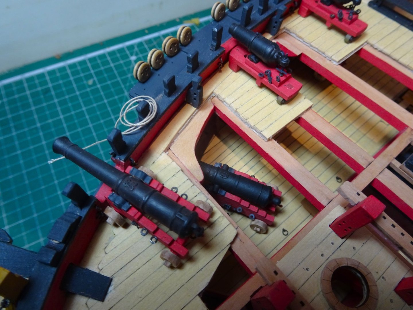
3760
My mainly open Foc’sle deck gives a clearer view of one of the Twenty-four pounders.
3747
Three after port lids in position.

3748
The port lanyards have been fixed into position from the inside.
The suggested tackle line of 0.1mm (1½” circ) is a little thin.
I used 0.3mm ø Syren line which equates to 2½” circ.
(Lavery comments that in the 1780’s port ropes were usually of 3” rope.)
3749
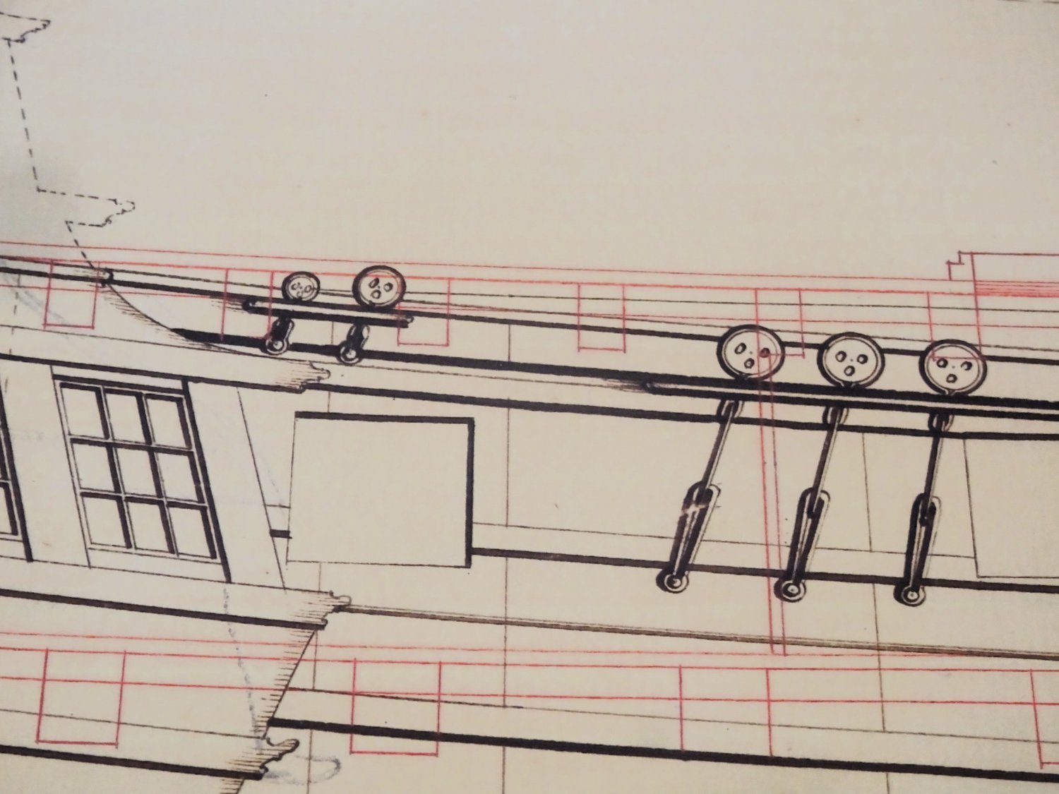
I was a little surprised by the inclusion of a single lanyard for the port lid tackle, particularly as the hull is that of a sixty-four.
The general arrangement for this period, except perhaps for smaller vessels, was for two lanyards per port, with lifting rings attached to the iron hinge straps.
On the kit this would entail drilling thro’ the straps, so the kit arrangement is probably a simplification to aid construction.
An alternative to aid ease of fitting would be laser board straps.
I have gone with the kit arrangement but if it annoys me enough I will re-visit.
3752
I’ve yet to fit the Qtr deck port lids, but as these are painted I will use the Pearwood laser parts.
B.E.
22/02/2024
-
Simply beautiful Håkan,
Glad to read that you are feeling better.
B.E.
- Keith Black, FriedClams, Nirvana and 2 others
-
5
-
-
Post One Hundred and forty-seven
A case for Indy – or the trials and tribulations of a shipaholic
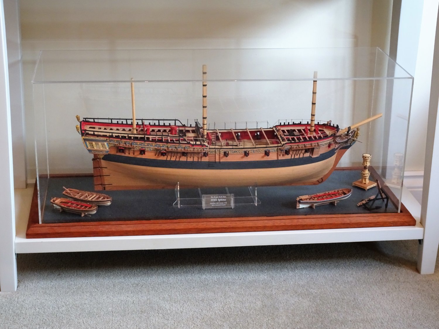
My previous supplier of acrylic cases, Paul, of Just bases, in Devon, retired in 2021 so I have to look for another source to provide the housing for the latest cuckoo in my nest.
The required internal dimensions are width 40”, depth 12” and height 17”. (To allow for stump masts.)
Still a sizeable space taker, but nothing compared to that required for a fully masted and rigged Indy. It’s a good job that I have no aspirations in that direction.

8808
By comparison my Sphinx (above) is housed in a case 30” x 10” x 12” a much more manageable option.
I found a home for Sphinx, but as I write I am struggling to find a space for Indy.
I have had a look around acrylic case suppliers, and they are expensive.
A random selection on the web.
(acrylicdisplaycases.co.uk) - £369 excl VAT
Display Cases | Striking Displays - £442.80 excl VAT
Model Display Cases & Cabinets | Luminati - £372.97 excl VAT
These figures also exclude any delivery charges.
A search on MSW brought up a reference by Dan (DB789) on his Grecian build to a company called DSC Cases.
These are wooden trimmed glass cases and one sized for my Indy would cost £220.80. plus £30 delivery.
I now only have one glass- cased model in the house, I made it myself many years ago, but these days I simply can’t be arsed.
2801
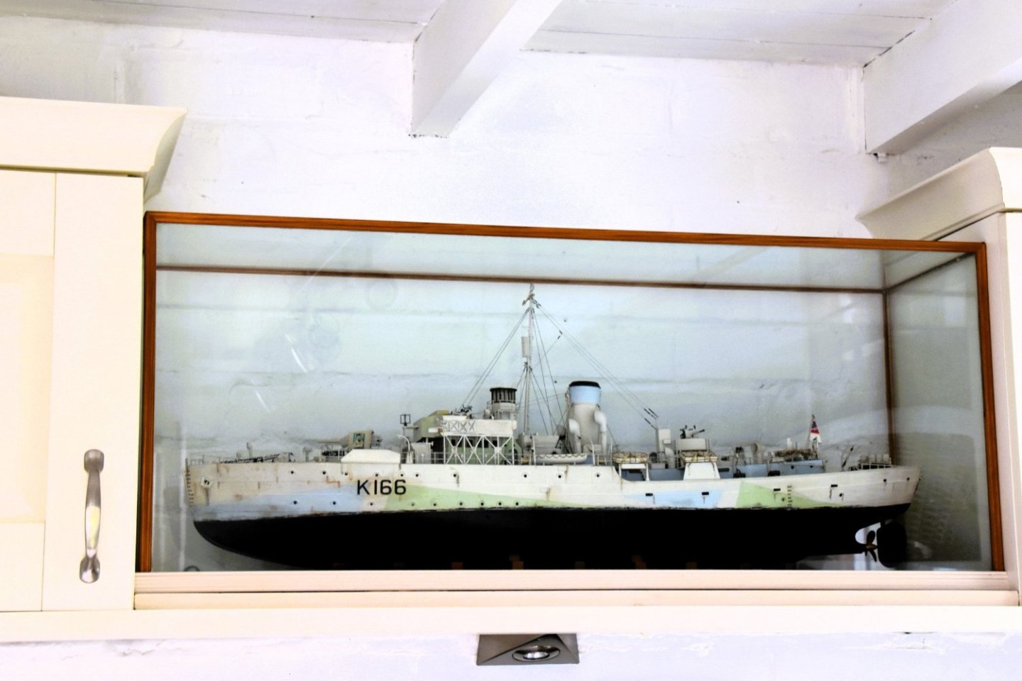
A favourite of mine, she sits high up between the wall cupboards.
Mrs W has mentioned more than once that she must be the only woman ‘blessed’ with having a Flower Class Corvette in her Scullery! 🙄
I digress, but it illustrates the shrinking availability of space after some five decades of model making. Most rooms have their allocation of ship models around the house, and I am now being pressed on ‘where you goin’ to put that.
Oh, I’ll find somewhere, sez I confidently, wandering around the house 40” rule in hand. 🫤
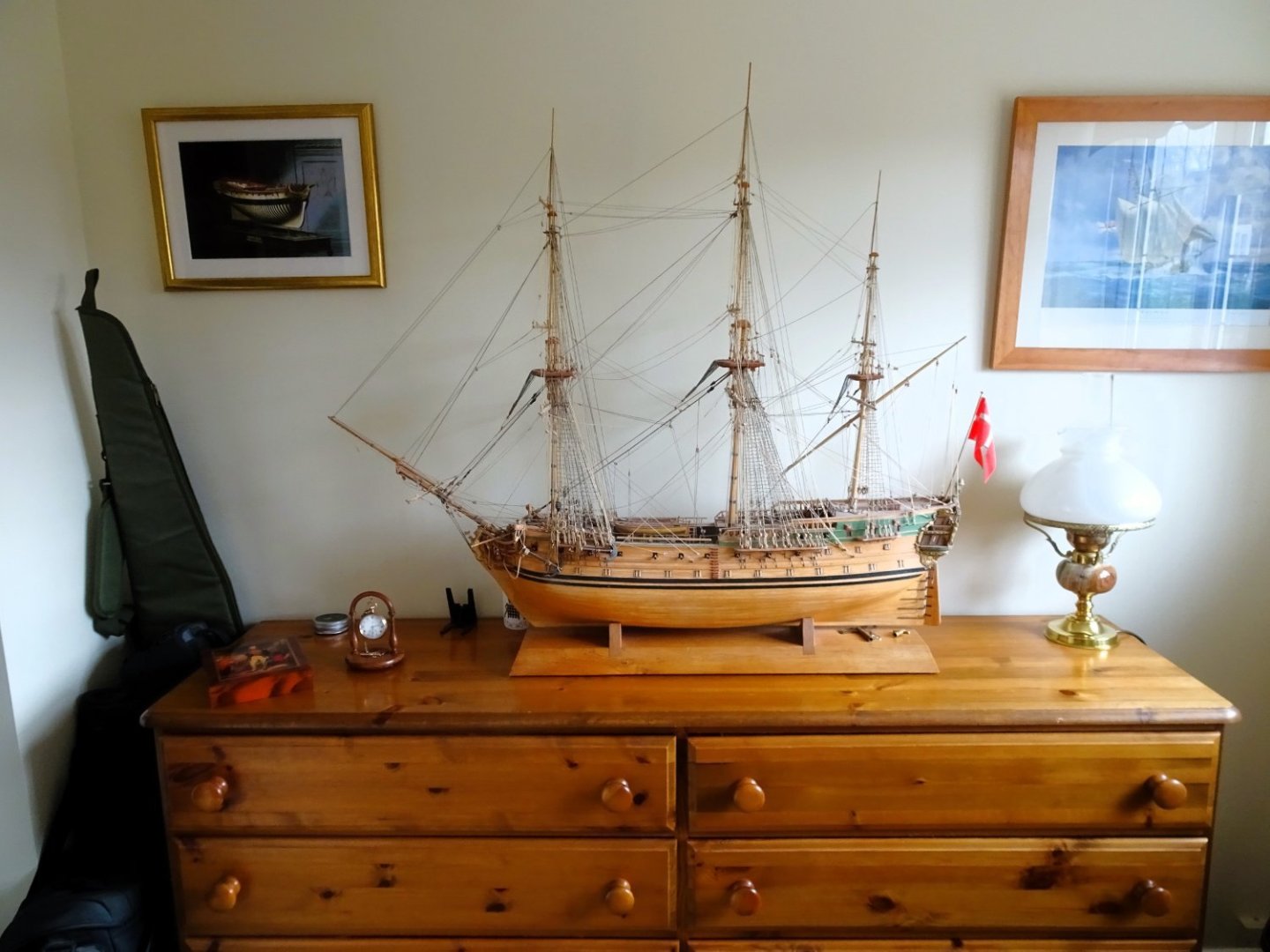
3730
The ideal place would be atop the chest of drawers in my office, but that is taken by Norske Love, a dusty but much-loved model, I really must get around to cleaning her.
I don’t think I could bear to move her out after all these years.
I have placed my order with DCS Show cases and I now have around a month to find a suitable place to display her.
Tick tock.
B.E.
19/02/2024
-
You surely do have the knack of finding lesser known subjects to model Nils, I too look forward to seeing this one develop.
B.E.
-
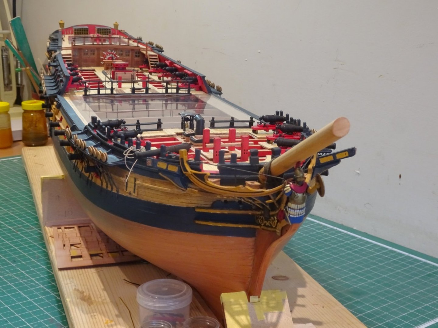
Post One Hundred and Forty-six
Thinking about Masts
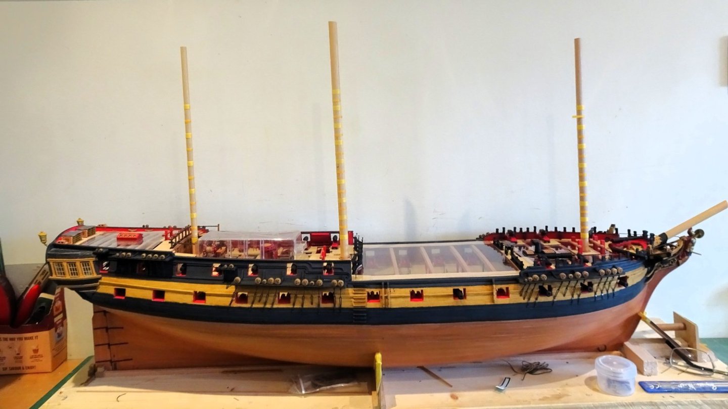
For a change of focus I have turned my attention to the fitting of masts, or stump versions thereof.
At this point I need to determine the overall height of the model so I can order the display case.
My masts will finish below the hounds but will include those elements that would appear on the length displayed.
These will include the wooldings, Cheeks, Front fish, and iron hoops.
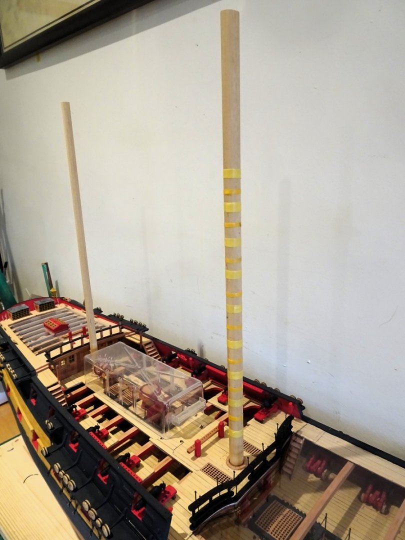
3711
I start with the Mainmast as this will determine the length of the other masts, and I first need to decide what overall height looks best.
They need to look proportionate, but I am conscious that the taller they are the bigger the case requirement.
3716
In Chris’s design the Mainmast has a set of nine wooldings with eight iron hoops between.
The iron hoops fit beneath the Front fish and cheeks, and the wooldings over both cheeks and fish.
3720
Gauging the relative heights.

3722
The Mainmast now sits around 15” above the stand with the Fore and Mizen reduced proportionately.
 3724
3724
I use only Ramin dowel for the lower masts, 12mm, 10mm, and 8mm.
-Copy.thumb.JPG.190e7cf1a23d5755a5a3894e4fa83eeb.JPG)
08070
Once treated with w-o-p the colour takes on a warm ochre tone as shown here on my Sphinx build.
Not included on the kit plans for either Sphinx or ‘Indy’ are the wooden hoops top and bottom of the wooldings that secure them in place.
B.E.
18/02/2024
-
On 2/8/2024 at 1:46 PM, yvesvidal said:
Thank you, Kevin.
While finishing the lamps, I have a few questions regarding the staff and ensign on these period ships:
- How was the ensign attached to the staff?
- Was the staff equipped with a pulley at the top, to raise the ensign?
Any precision or explanations would be much welcome.
I thank you in advance.
Yves
Hi Yves,
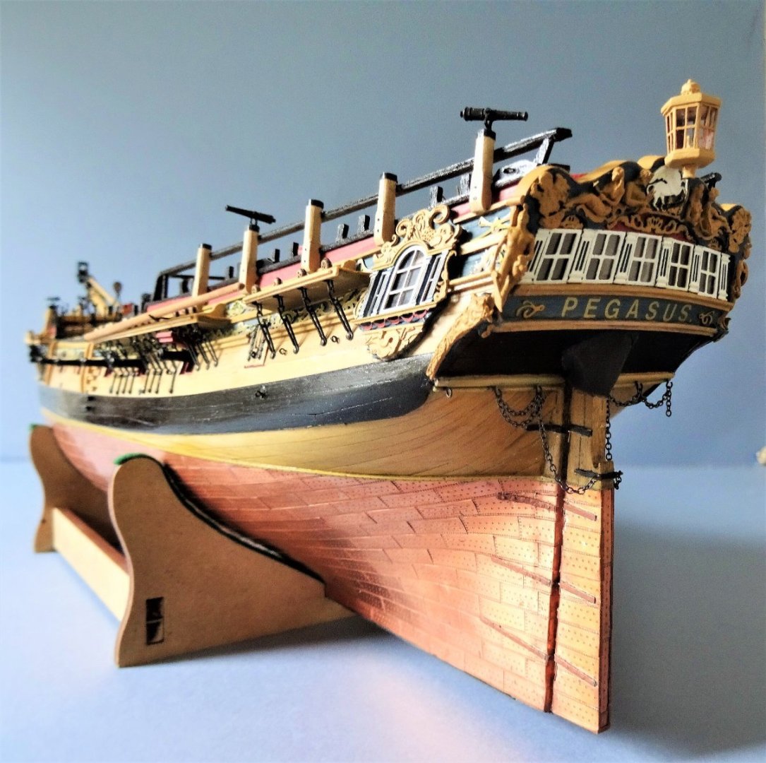
This is how I dealt with the Ensign staff on my Pegasus build.
068
The truck was fitted with two sheaves.
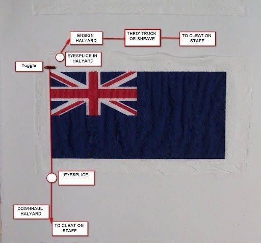
This is a schematic of how I attached the Ensign.
Hope it helps.
B.E.
- mort stoll, mtaylor, John Ruy and 2 others
-
5
-
You've developed a great range of smaller naval ships Chris, including cutters for every taste.
A re-vitalised Sherbourne is an excellent choice.
I may well be tempted as I inexorably move towards my dotage.
Well done!
B.E.
- Loracs, chris watton, Pitan and 6 others
-
9
-
Thank you Nils, but every time I do a set of macro's I see another little area needing attention, but getting there by degrees.
B.E.
- hollowneck, mtaylor and Mirabell61
-
3
-
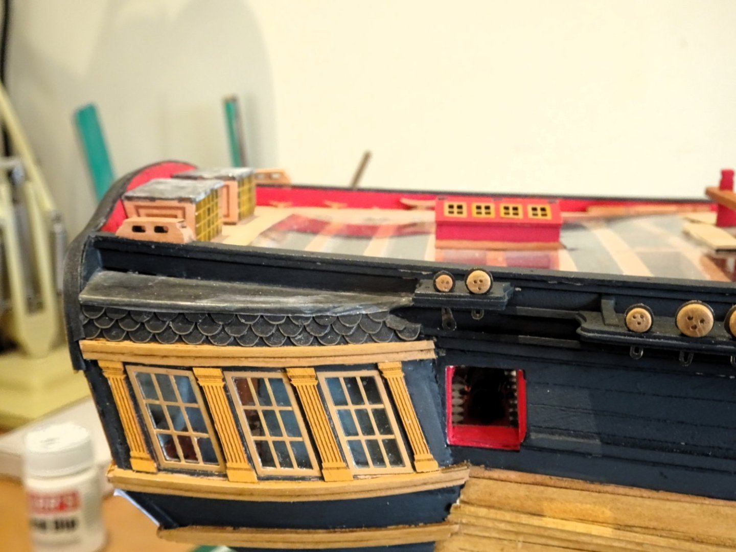
Post One Hundred and Forty-five
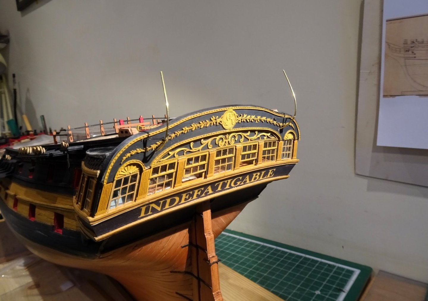
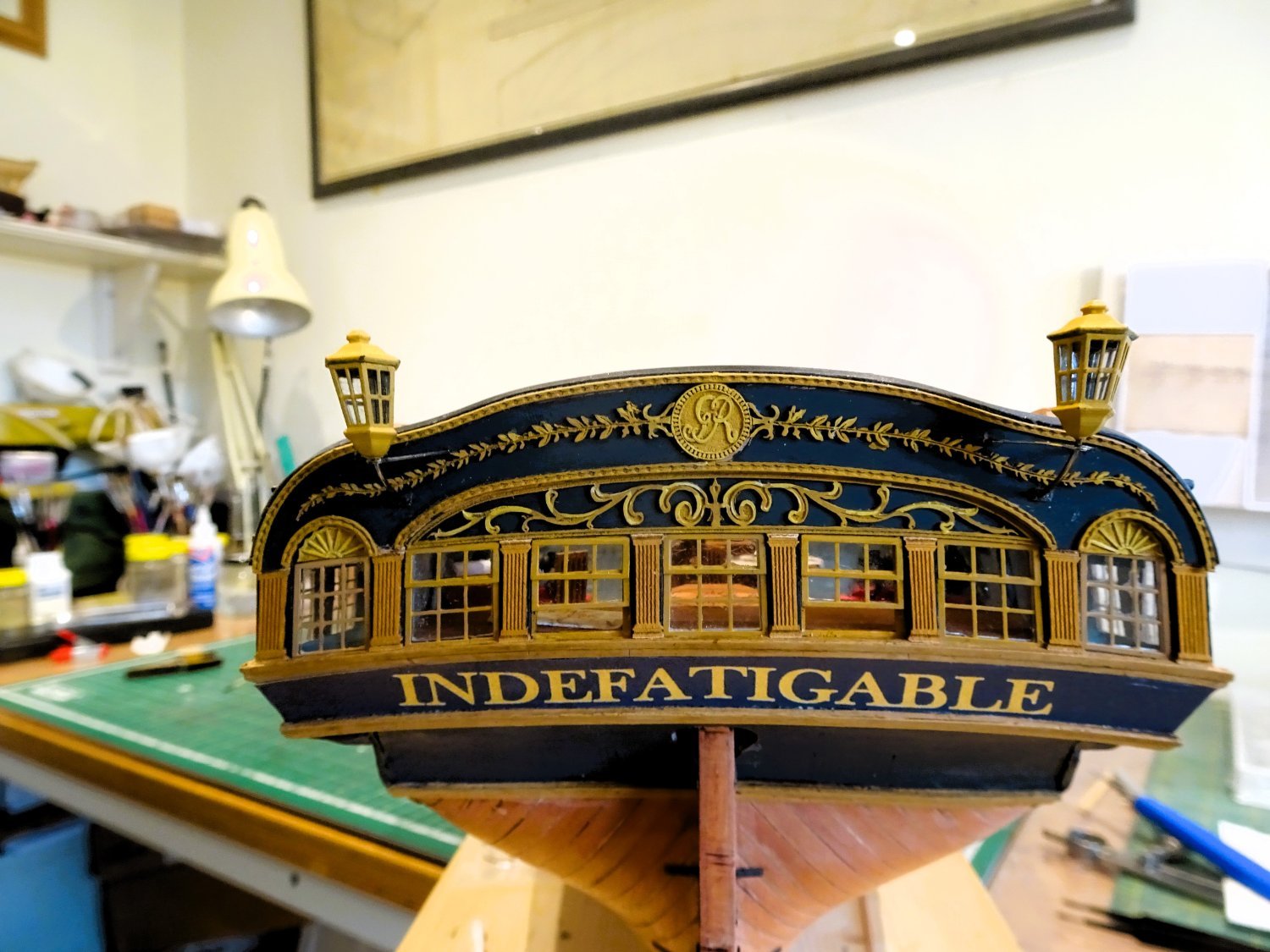
Stern Lanterns
A pair of Resin lanterns are provided in the kit with Brass etch brackets. Pre-cut acetate glazing that only requires folding to shape, completes the package.
Beautifully crafted, but my initial impression was that they looked a tad on the small size, but I needed to see them on the model.
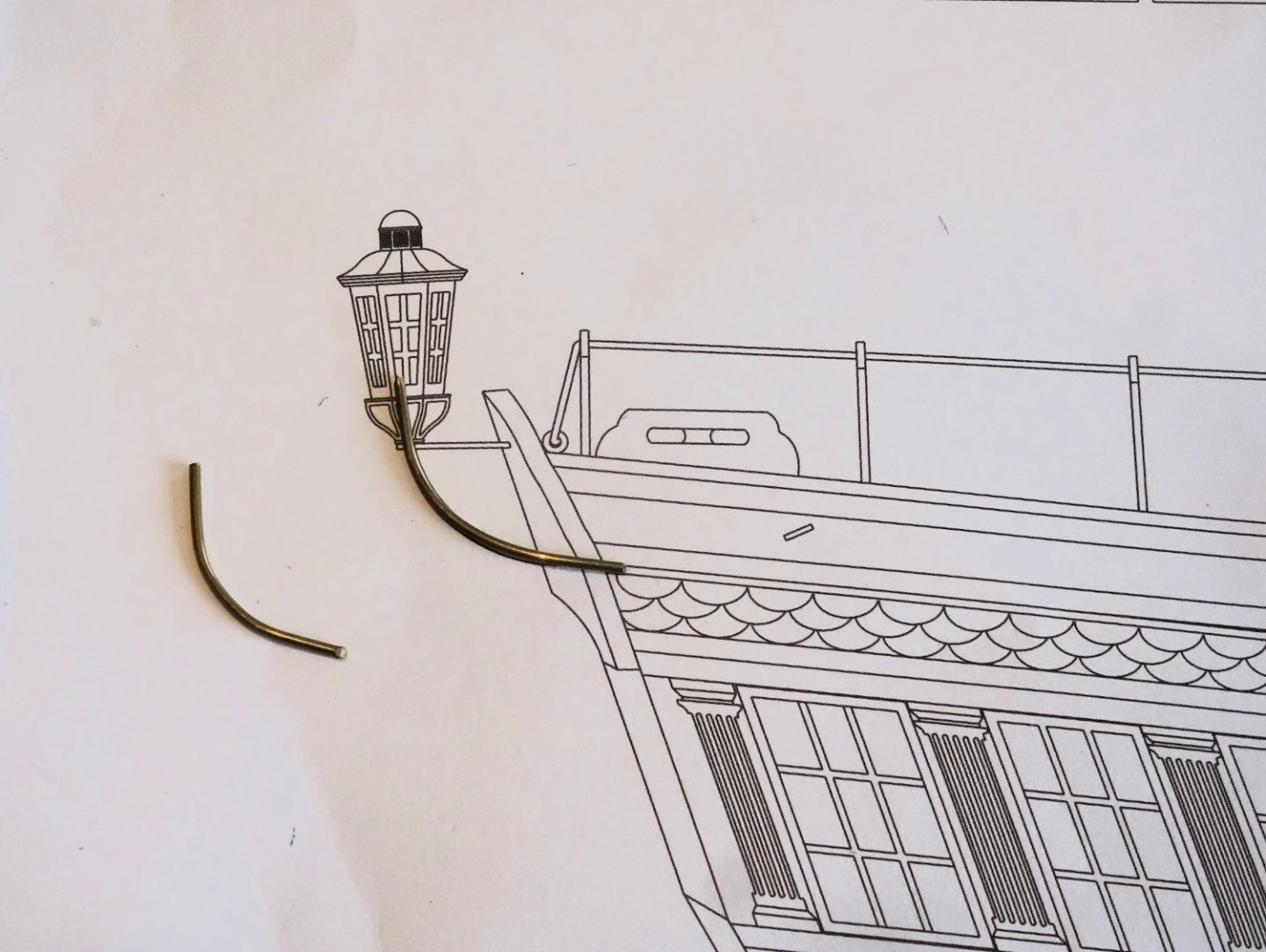
3685
The plan is used to get the line of the crank.

3686
Assembly is simple, the tricky part if it can be called that, is fitting the ironwork to the stern gallery, particularly when you have lost track of the fixing holes.🙄
3688
I found it easier to use longer lengths of 0.8mm brass wire to form and fit the cranks.
3690
The only addition I made are fixing plates to the stern.
Apart from that I had to file the bottom of the clear glazing a tad to allow the lantern tops to sit down on the framing.

3694
Is my initial impression that they may be a little undersized borne out?
Perhaps not when compared to the contemporary model of Amazon below.
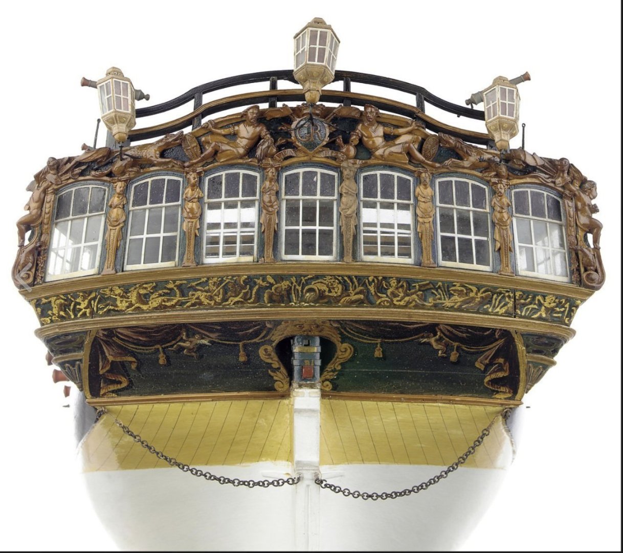
Amazon Stern
I could not find original records relating the ships lantern sizes by rate, and of course I’m not privy to the information used as a basis for the ‘Indy’ Lanterns.
I did check out relative sizes from my available sources, and for what it’s worth this is what I gleaned.
Victory - side lantern 57½” o/a height (22.8mm at 1:64 scale)
Bellona – 62½” o/a height (24.8mm at 1:64) scale drawing AotS book.
Pandora – 40¼” o/a height (16.0mm at 1:64) scale drawing AotS book.
Leopard (50 gun ship 1790) - 53” o/a height (21mm at 1:64) Scale drawing John McKay from The 50-Gun Ship.
Sixth rate sloop– 51” o/a height (20.25mm at 1:64) scale drawing FFM Sixth rate book from a reconstruction.
Indefatigable – 44” o/a height (17.5mm at 1:64 scale) - actual kit fitting.
Another option is the exquisite Boxwood lantern 3/16th (1:64) scale from Syren.
This measures 7/8th" (22.25mm) which equates to a 56” o/a height.
1827
I used this on my Pegasus build, and I think it is a viable option for ‘Indy’.
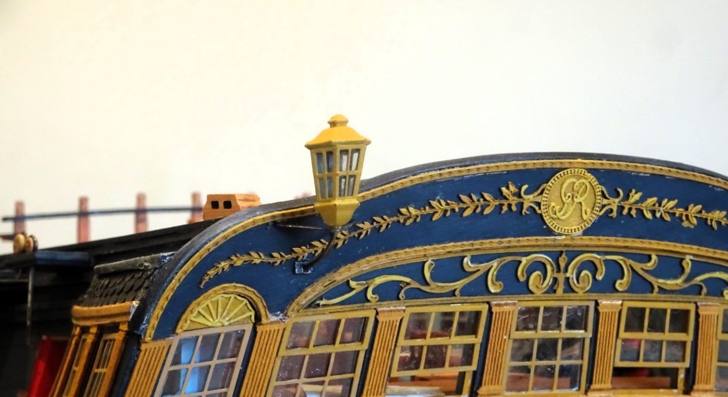
3704
On balance I think I will stick with the kit version.
3702
3697
Onwards,
B.E.
16/02/2024
-
Post One Hundred and Forty-four
Strops, Chains, and Plates. (Part two)
The brass etched chains and plates are very nicely made and scaled, and as with the strops took the blackening well.
There are two main considerations in fitting the chains and plates.
1. The angle; they should follow the line of the shroud or stay to which they relate.
2. The middle and lower links of the chains should be taut when drilling the hole in the hull where they are fixed by the Preventer Plate.
I used a 0.4mm ø drill for the fixing holes and blackened pins as supplied with the kit.
A pin pusher was used to drive the pins home, I found glue was unnecessary.

1864a

1866a
1868a
My only diversion from the kit plan is in respect of the backstays on the Mizen stool.

1869a
I shortened the upper link for the Mizen Topmast backstay and used a smaller version of the lower link. (left over from a previous build)
1871a
A smaller 2.5mm deadeye was used for the Mizen T’gallant Backstay.
I made a new combined strop and strap from some 0.5mm brass wire, silver soldered for the strap. This allows the deadeye to sit as per the Adm plan.
1872a
When it comes to the Deadeye iron work Chris has done a great job, the plans and drawings clearly identify the relevant parts and their fixing points.👍
B.E.
14/02/2024
-
That foremost Catharpin doesn't look right to me Glenn, severely chafing against the mast.
As I understand it catharpins were not applied to the foremost shrouds for that very reason.
Starting with the ninth shroud(aft) I think alternative fixings to the 7th, 5th, and 3rd shrouds are a more likely arrangement.
I know the plans show the catharpins attached to the first shroud but I don't think that is correct.
1619
As you can see here on Victory, they don't extend to the first two shrouds and clear the back of the mast.
B.E.
-
Post One Hundred and Forty-three
Strops, Chains, and Plates. (Part One)
Time consuming items, even before assembly starts.
Removing from the fret, sorting the various components, prepping for chemical blackening, and the process itself.
3626
It helps to have a system to speed up the job and to avoid mixing up the parts.
There are a lot of individual items to be blackened, which are done in batches per side.
My procedure:
Clean with fine steel wool.
Acid dip and rinse.
Immerse in diluted blackening fluid. My preference is for Carr’s Metal black for brass.
Rinse
Buff and repeat to taste.
3628
3630
Using the above system the strops blackened quickly and following a buff required very little re-treatment.
3631
The strops fit beautifully thro’ the channel slots without any need for adjustment.
Fitting the Deadeyes into the strops is done with care to reduce the risk of scarring the blackened strops.

3634
These pliers are perfect for the job.
3644
3636

3652
For the aftermost strop on the Mizen stool which is for the T’gallant Backstay I have replaced the 3mm deadeye arrangement with a 2.5mm size, to better reflect the lighter line.
3654
The T’gallant Backstay is of 2½” circ. This equates to a scale diameter of 0.3mm, compared to 0.5mm ø for the 4”circ Topmast backstays.
3656
The smaller version dispenses with links and chains and is fixed directly to the hull adjacent to the roof line. This accords with the Official Adm plan.
One additional benefit is that there is no need to try and cram an additional chain fixing in the very small space between the gallery lights and the aftermost gunport.
Two full days have been spent on the starboard side thus far, but a race it ain’t.
The second stage is fixing the chains and Preventer plates to secure the strops.
Hoping that the Preventer plates fall right on my build.🤞
B.E.
10/02/2024
-
-
-
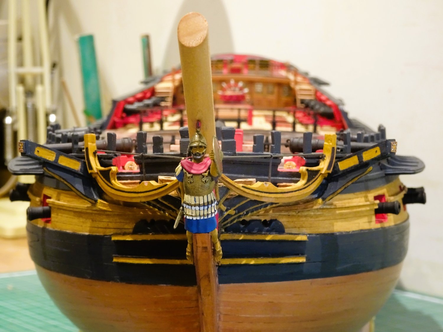
Post One Hundred and Forty-two
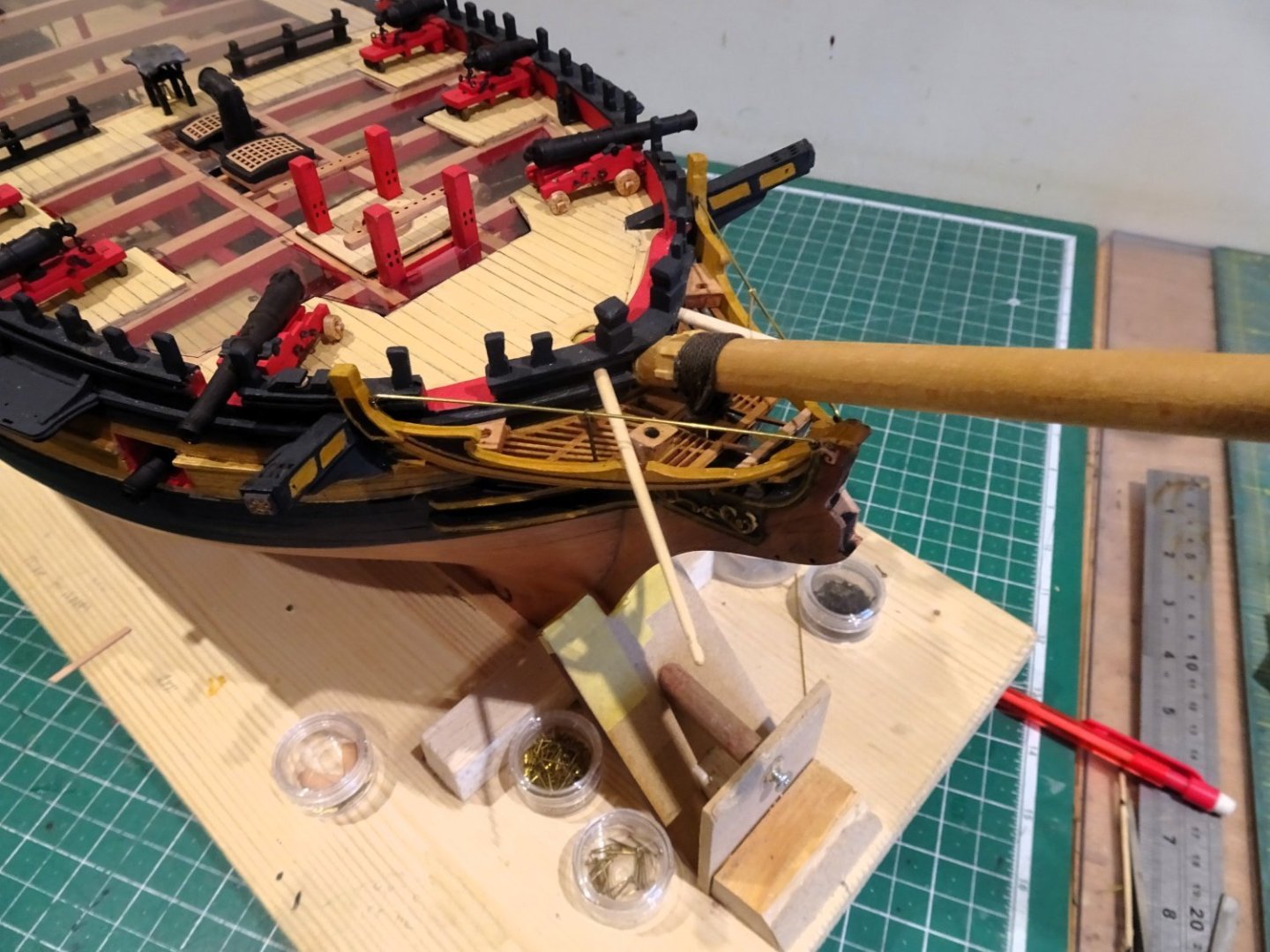
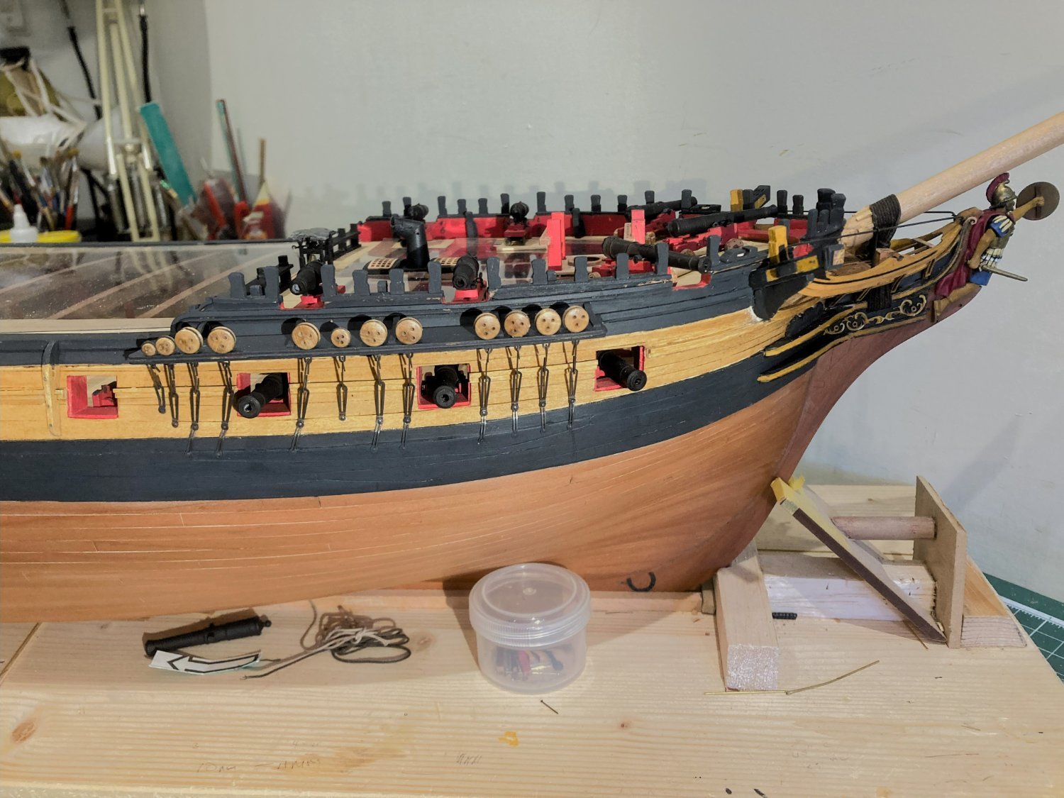
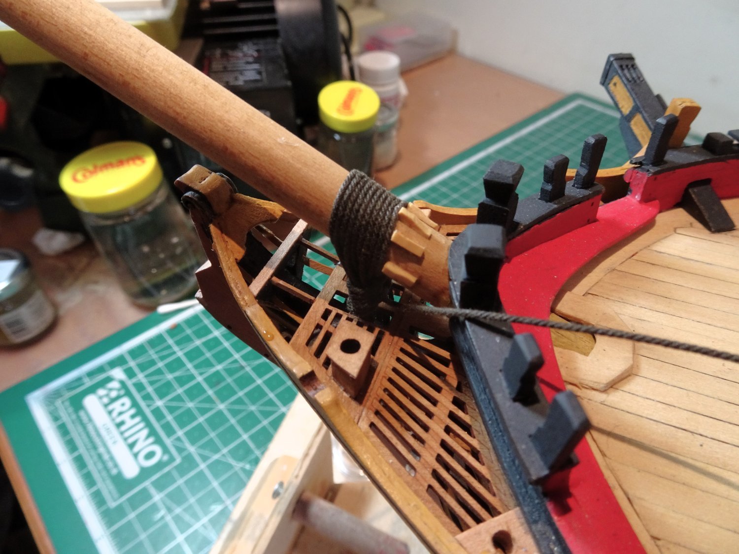
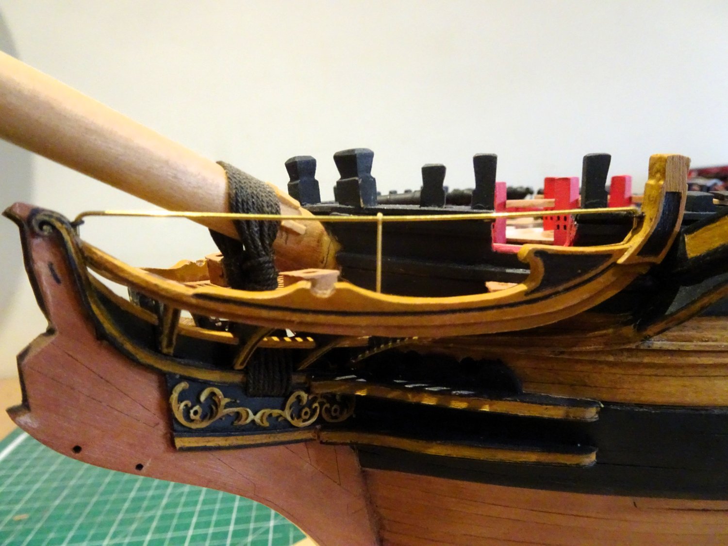
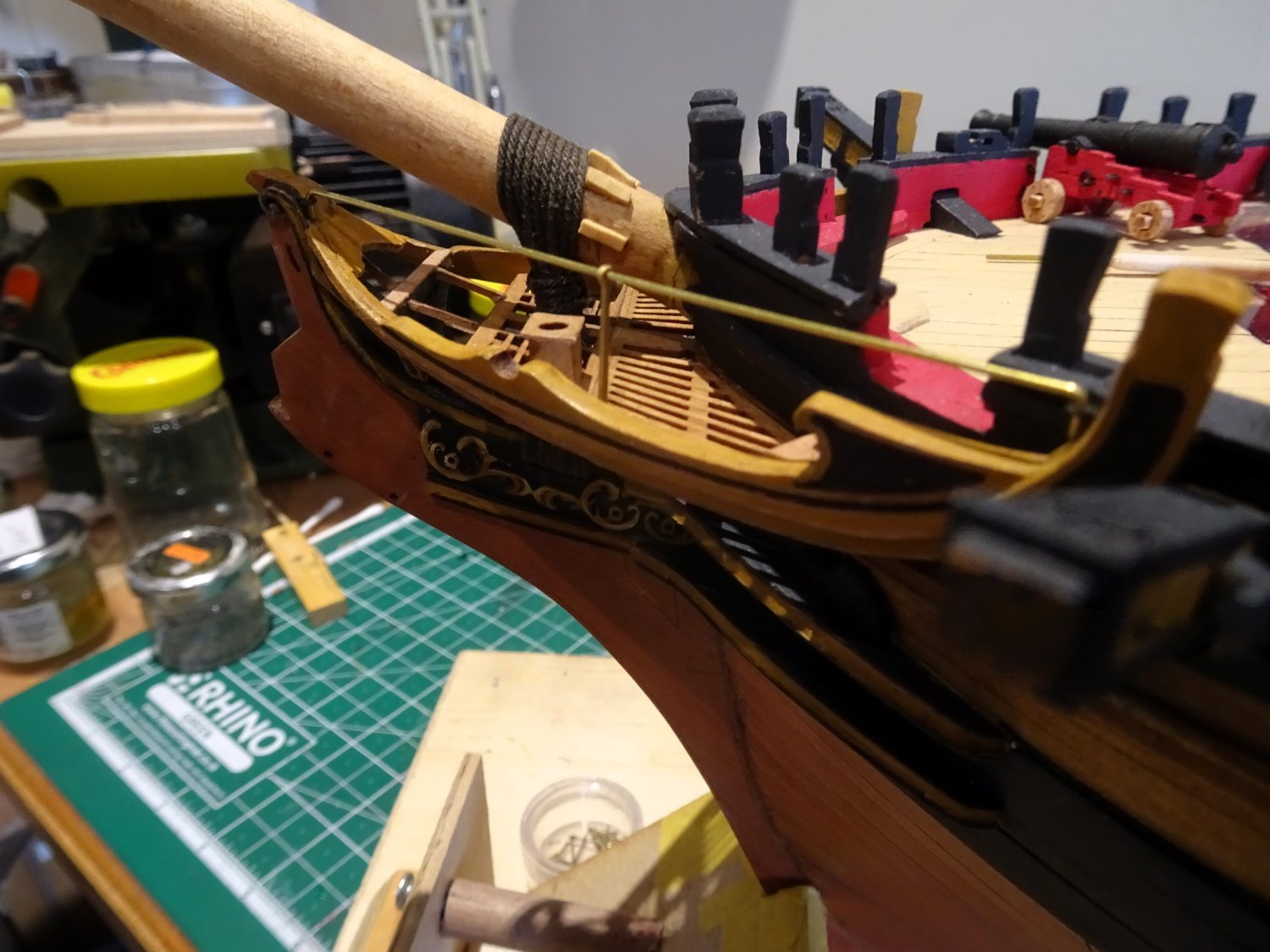
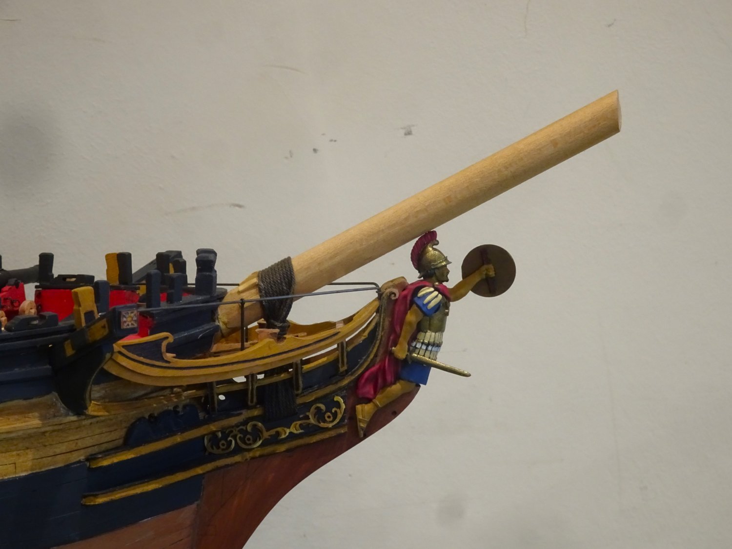
Back to the head
The stump Bowsprit has been secured in place.
I like to add fittings to the Bowsprit as far as its length permits.
Gammoning
For a Sixty-four, rope of 7”circ is required, scaling to 0.88mm ø.

3597
The first job is to determine the position of the gammoning cleats.
3598
The kit provided cleats (M73) looked a little undersize to my eye, so I remade the five required from some Boxwood section.
The line
I used Syren 0.88mm ø line dyed with Colon dark Jacobean oak wood dye, which is my go-to for standing rigging. I have never been keen on kit provided black line.

3604
It is important to ensure that enough line is taken to complete the turns and frapping. I allowed 60” to complete the job, I had 12” left over, which is just about right.
The gammoning starts thro’ an eye splice on the Port side, and the line twists as it passes from fore to aft with each turn.
Steel refers to cross turns of the frapping.
when all the turns are passed, and hove tight, they are frapped together in the middle, by as many cross turns as are passed over the bowsprit, each turn hove tight: the end of the gammoning rope is then whipt, and seized to one of the turns. the frapping increases the tension; and adds to the security acquired by the purchase.Horse
One of the features of the head almost entirely missing from kits is the iron (Horse) a rail that runs between the Main rail fore and aft supported by an iron stanchion. The horse hooks into eyebolts in the main Rail.

3607
Often this has netting strung along it as a safety feature.

3608
I like to add this fitting, fairly simple, if you have the makings.
I use lengths of 0.7mm brass rod, and eyebolts and stanchions from the kit.
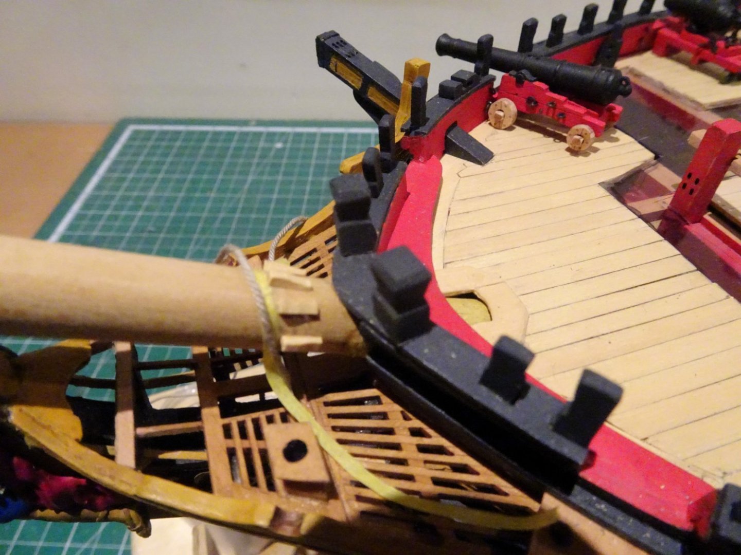
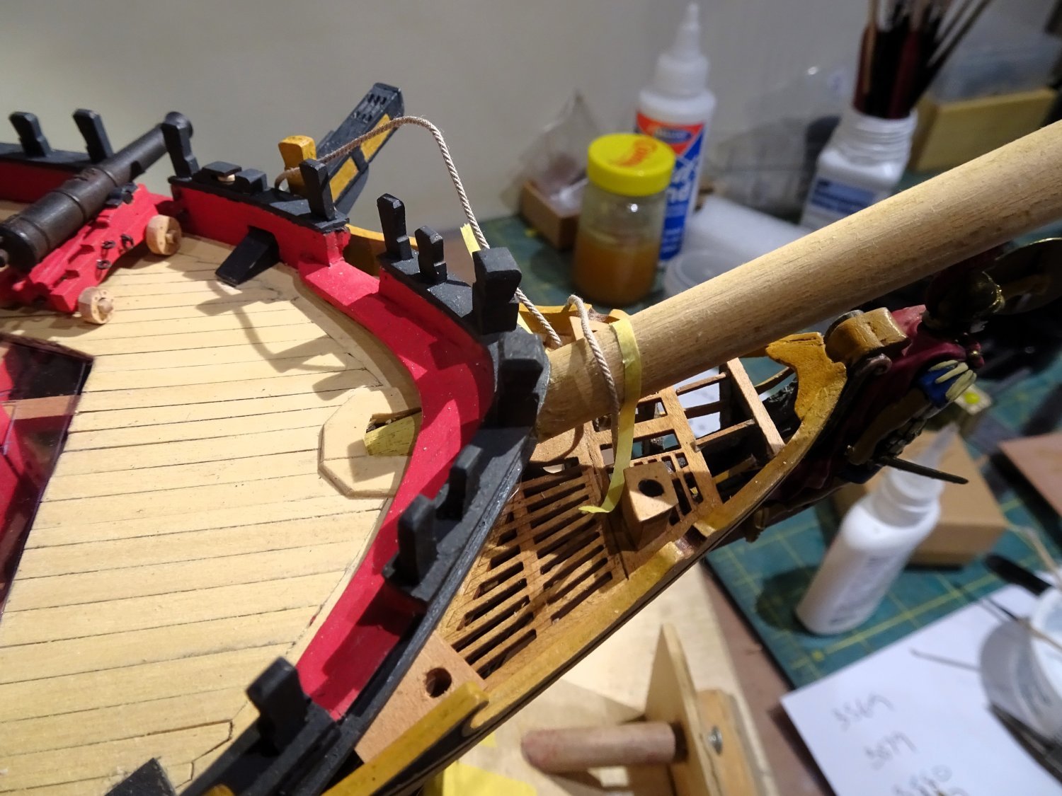
Boomkins
These simple to make fittings proved not so simple to fit.
Secured adjacent to the knightheads at the bow they run in a downwards direction where they are secured by a capsquare as they cross the False Rail.
3613
My problem is that they are obstructed by the seats of ease which I needed to modify slightly to give clearance.
Still work to do, the recess for the Boomkin needs adjusting for the angle, and there are capsquares to make.
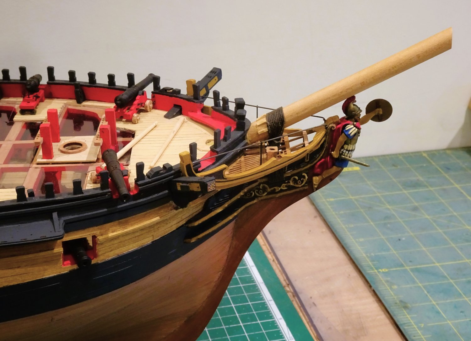
At last, I can put the impressive figure into place.
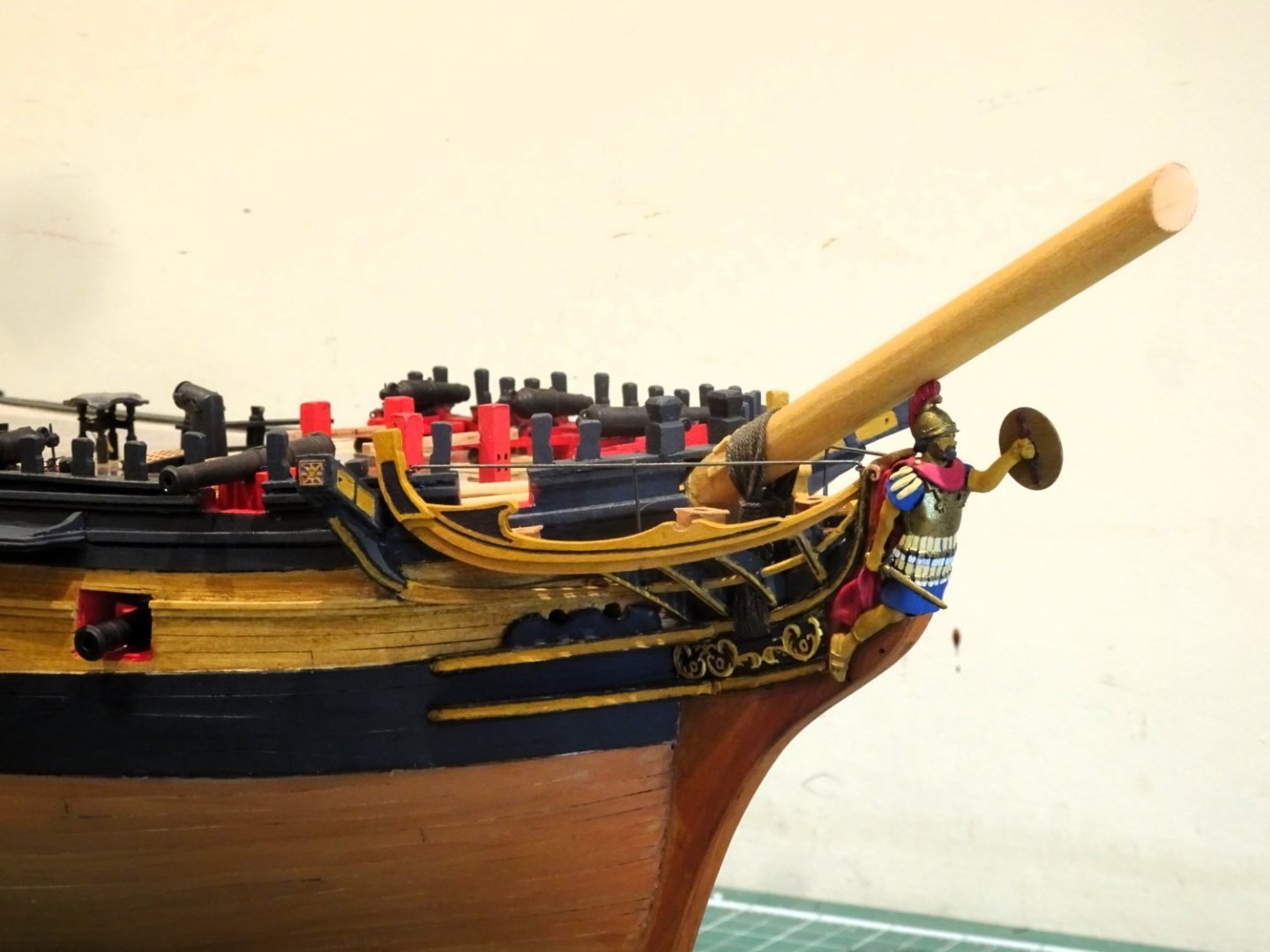
3615

3617
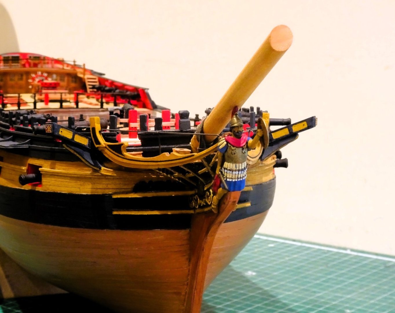
3619
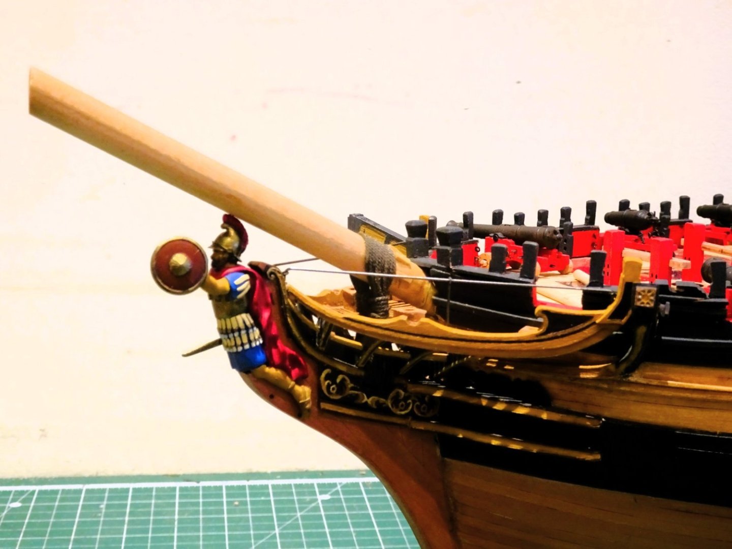
6320

3621

3624
The Head is all but done now, back to the repetitive task of deadeye stropping and chainplate fixing.
B.E.
08/02/2024
- KARAVOKIRIS, AJohnson, BenD and 18 others
-
21
-


-Copy.JPG.347f4a9741b4f45806f87580d332f62c.JPG)


HMS Indefatigable 1794 by Blue Ensign - FINISHED - Vanguard Models - 1:64 scale
in - Kit build logs for subjects built from 1751 - 1800
Posted
Thank you, Daniel, hope things are good with you.
I have not seen any contemporary information regarding the lead of the pendant and I don’t know whether the knot is a modern convention simply to secure the line, or if a further line was eye spliced to the knot, and set up with a tackle.
The arrangement on that wonderful Victory model would seem to fulfil most model making requirements.
Harland (Seamanship in the age of Sail) covers various mishaps to wheel and rudder and courses of action to counter them. He mentions the pendants in relation to the loss of the rudder head and use for steering. He shows a tackle secured to a beam athwartships, and a jury rig to the wheel on a Frigate.
Re: the leather tubes for the lid lanyards; I did the same as you for the stern ports, but for broadside ports, I am thinking of using the sleeves from telephone wire – if I can remember where I have put my supply.🤔
Regards,
B.E.