.JPG.ca33079f5815b861e67b9c2cccd37982.JPG)

Blue Ensign
-
Posts
4,576 -
Joined
-
Last visited
Content Type
Profiles
Forums
Gallery
Events
Everything posted by Blue Ensign
-
 I just love the sweep of your hull timbers up to the the lower counter, and I think you were right to remove the first go at the counter frieze. I too am a fan of Chuck's paper friezes and they look so good on Winnie, I adapted them for Sphinx. Beautiful work Glenn. B.E.
- 840 replies
-
- 5
-

-
- winchelsea
- Syren Ship Model Company
- (and 1 more)
-
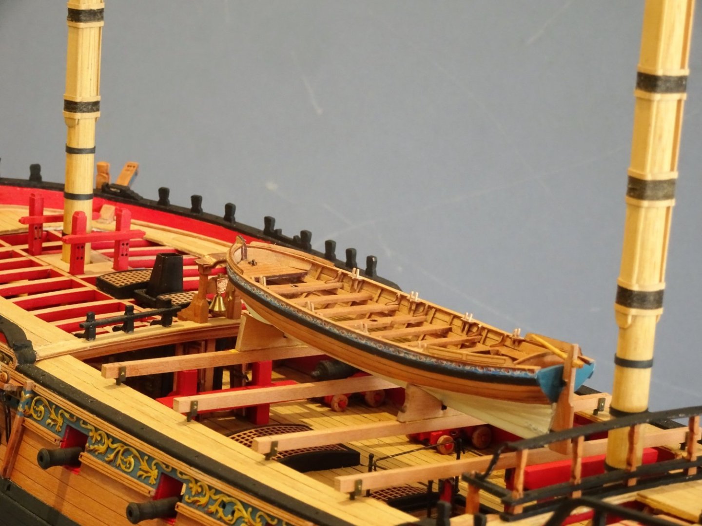
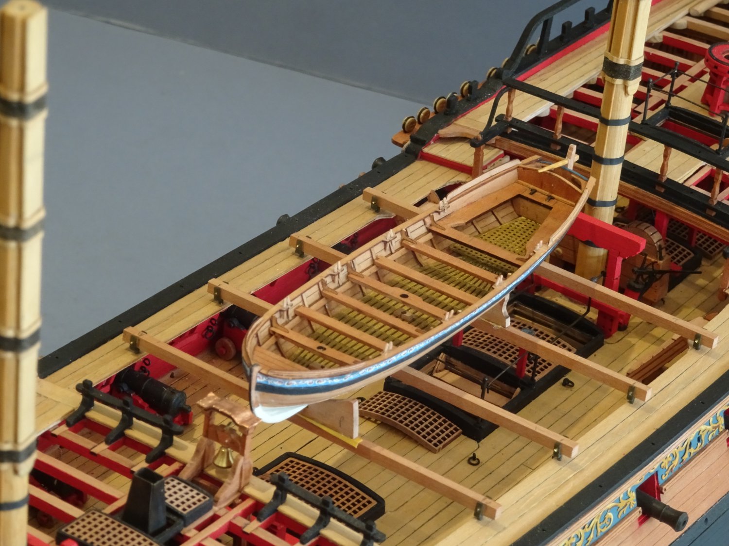
According to Brian Lavery (Arming and Fitting) skid beams were standard by 1750, initially with iron crutches to secure them, but he indicates that their use on Ships of the line became more permanent by the 1780's. His comments regarding frigates which is more relevant to Winchelsea is that; Frigates were rather slower in adopting gangways and boat booms and do not appear to have them until the early 1800s. I think Chuck's approach of spare topmasts to support a ships boat feels more appropriate, and more aesthetically pleasing in relation to 'Winnie' of 1764. B.E.
- 1,784 replies
-
- 3
-
-
- winchelsea
- Syren Ship Model Company
- (and 1 more)
-
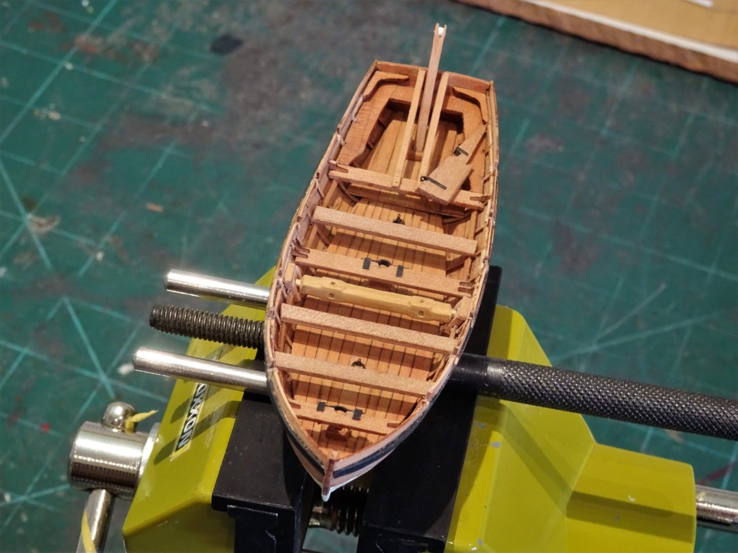
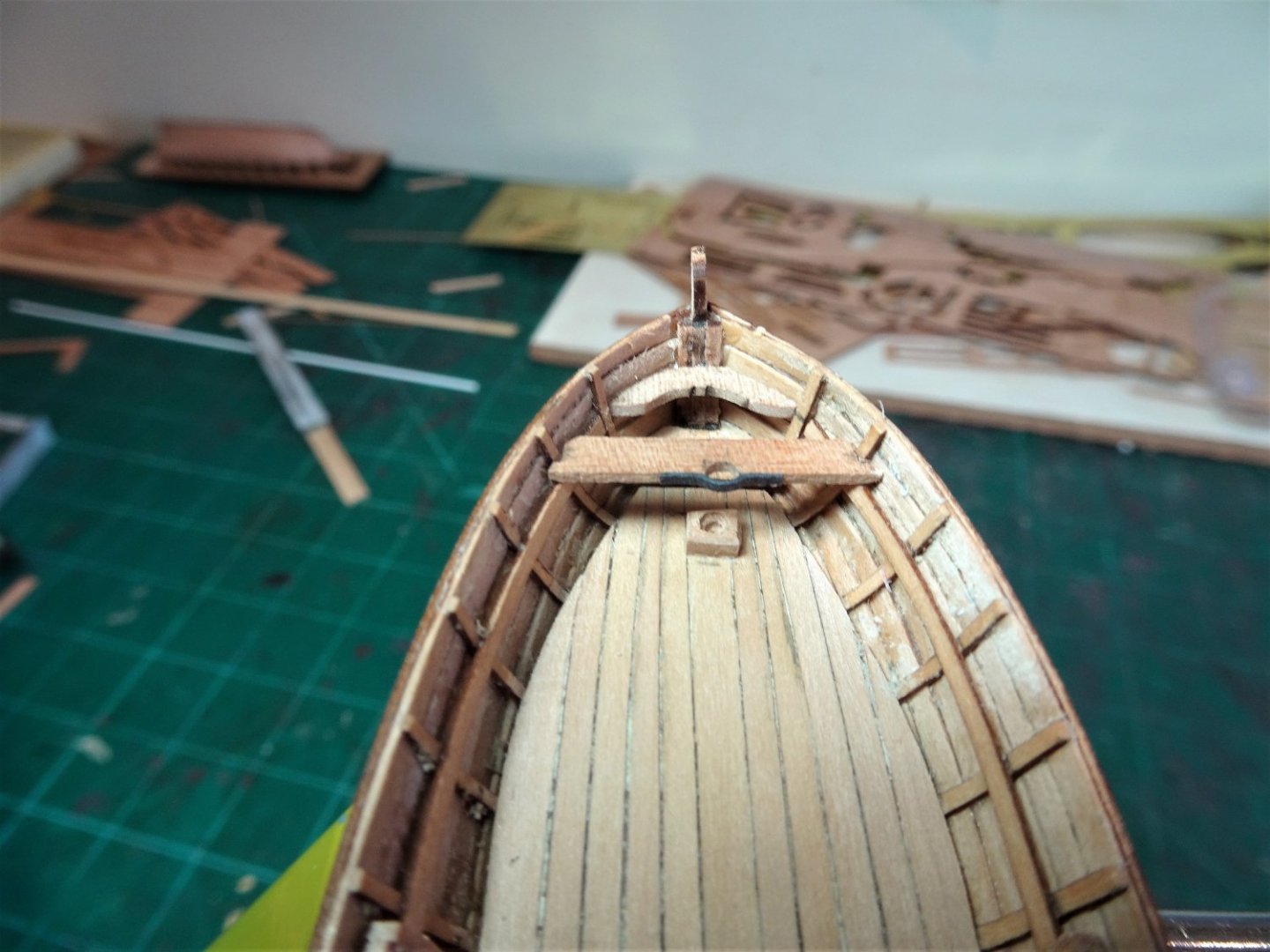
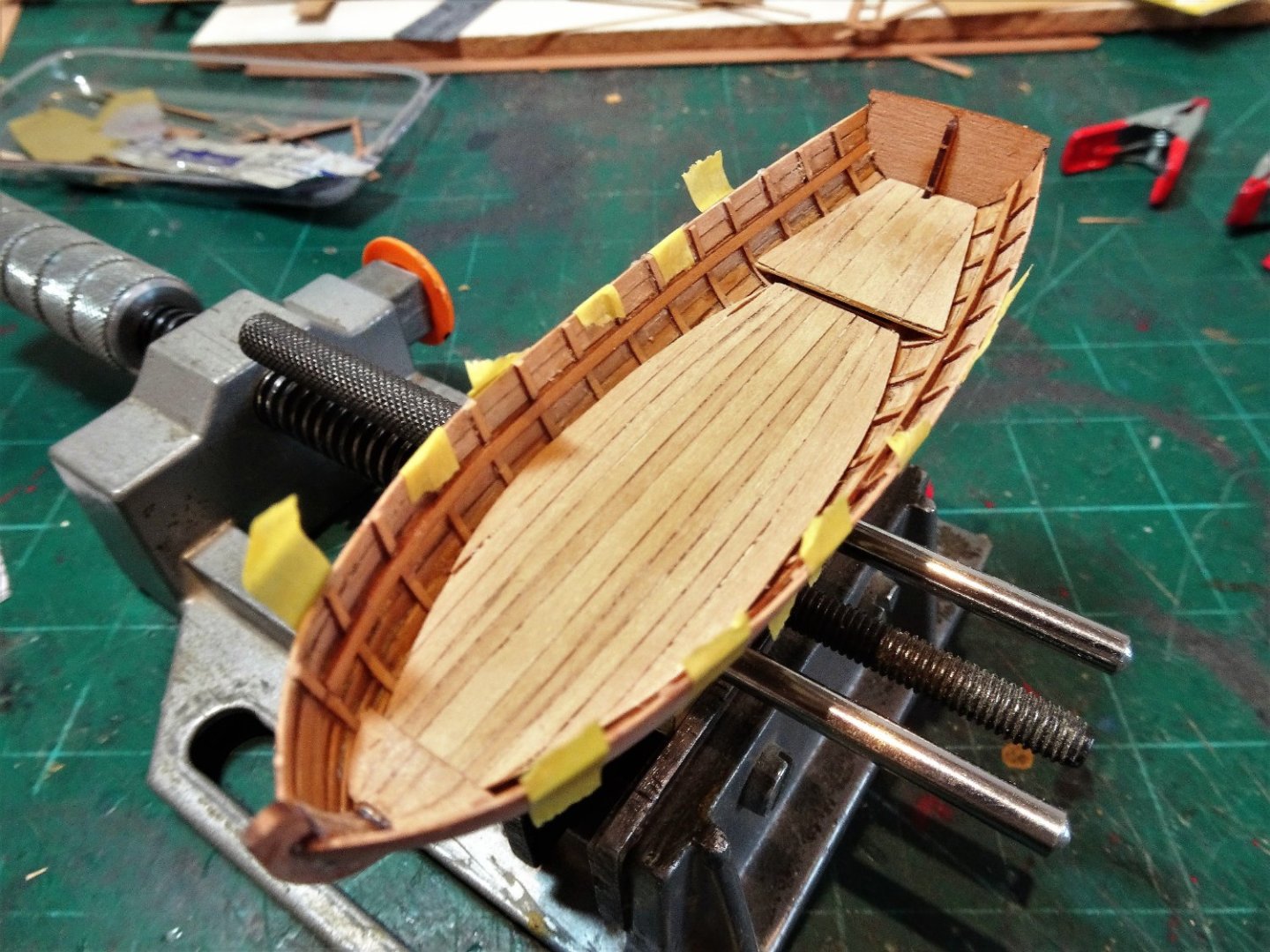
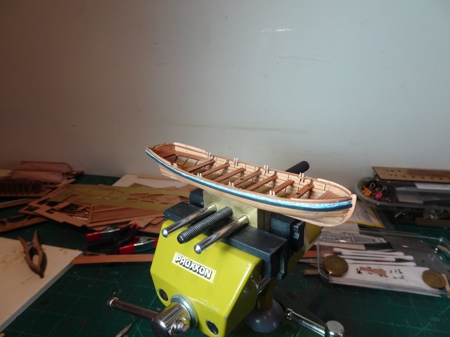
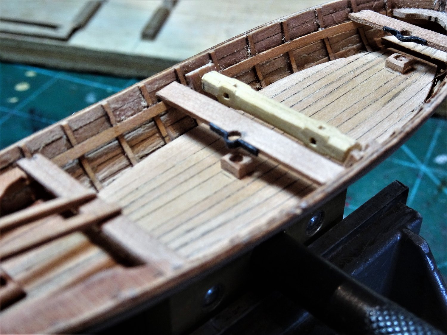
Post One hundred and Sixty-one. The Launch – completion 8258 Busy, busy, in the workshop, a case of spot the the boat. 8264 With the wash-boards attached a fair bit of cleaning up is required, but overall I am satisfied that the modification was worth it. 8265 The Rudder The final addition; as with the other boats I put the kit arrangement aside in favour of a working rudder using the typical long pintle at the lower end. 8254(2) The long pintle is silver soldered using a fine brass eyebolt and pin. 8255(2) A brass micro tubing sleeve is used to give support where it fits into the lower stern post. 8266 The long pintle is particularly important in relation to the Launch as to work the Davit the rudder would need to be removed quickly and easily. 8260 8262 If the rudder is shown in place, then the Davit is stored in the Stern-sheets. 8270 If the Davit is shown in place, then the Rudder is not fitted, it would be taken onboard. 8274(2) For display purposes I will have the Davit in place as it is a launch specific fitting. 8276(2) With ten days labour I think I’ve had my moneys worth out of the Launch kit, a lot of modifications in one small hull. 8279(2) Two down, one to go. B.E. 29/08/2022
.thumb.JPG.b46b441bf1ac9ea63e66ceb678d27e73.JPG)
.thumb.JPG.1d655d9b68cd0b9a0a657efe0ae0ffd5.JPG)


.thumb.JPG.f2f122a103f16a99de78ad38b8263c47.JPG)
.thumb.JPG.a80faa0edc3c76cef6eec2a350f8f431.JPG)
.thumb.JPG.45907c557863bbdc9e80cb40a3fbeb99.JPG)
- 857 replies
-
- 27
-
-
- Sphinx
- Vanguard Models
- (and 1 more)
-
Thank you shipman, for your kind words and support of my logs. I do enjoy doing this stuff as part of the modelling experience, and it's good if others find it of use. Regards, B.E.
- 857 replies
-
- 4
-
-
- Sphinx
- Vanguard Models
- (and 1 more)
-
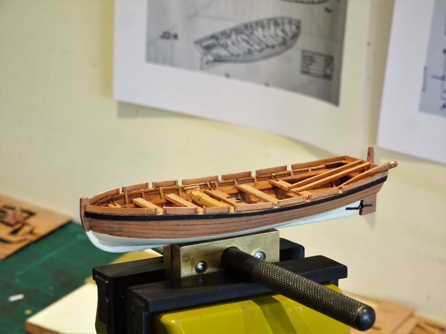
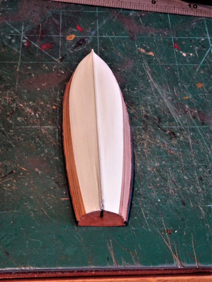
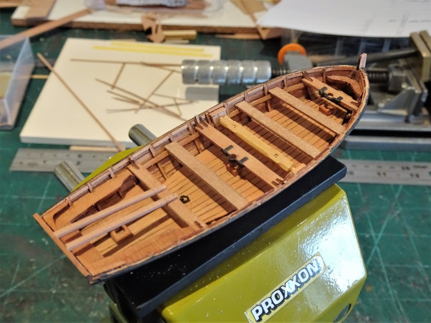
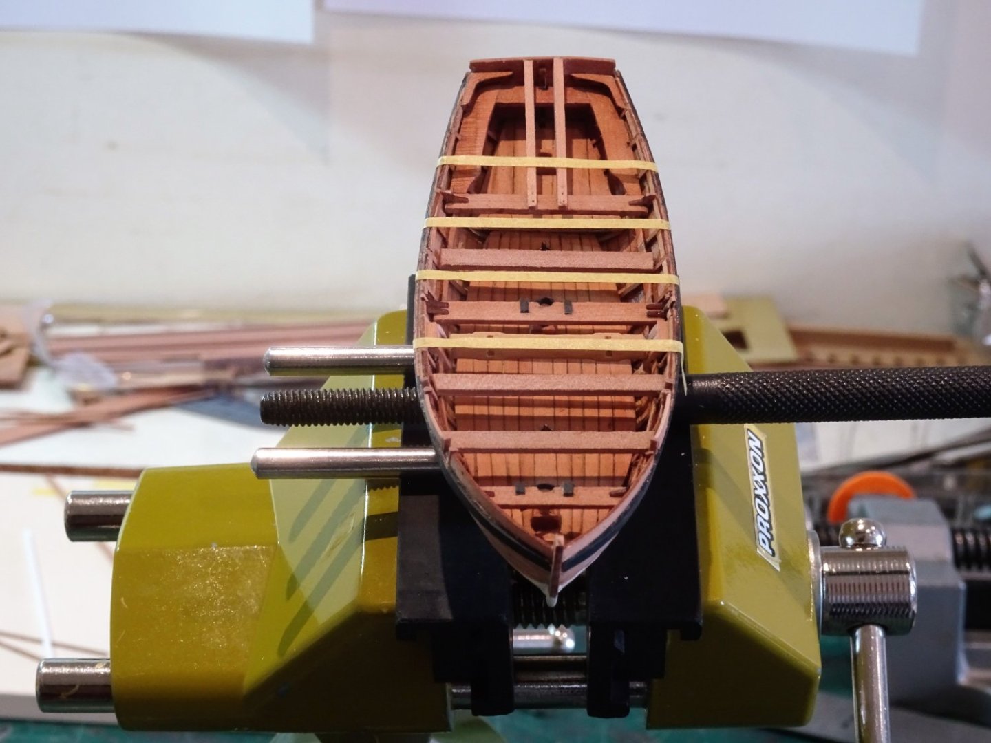
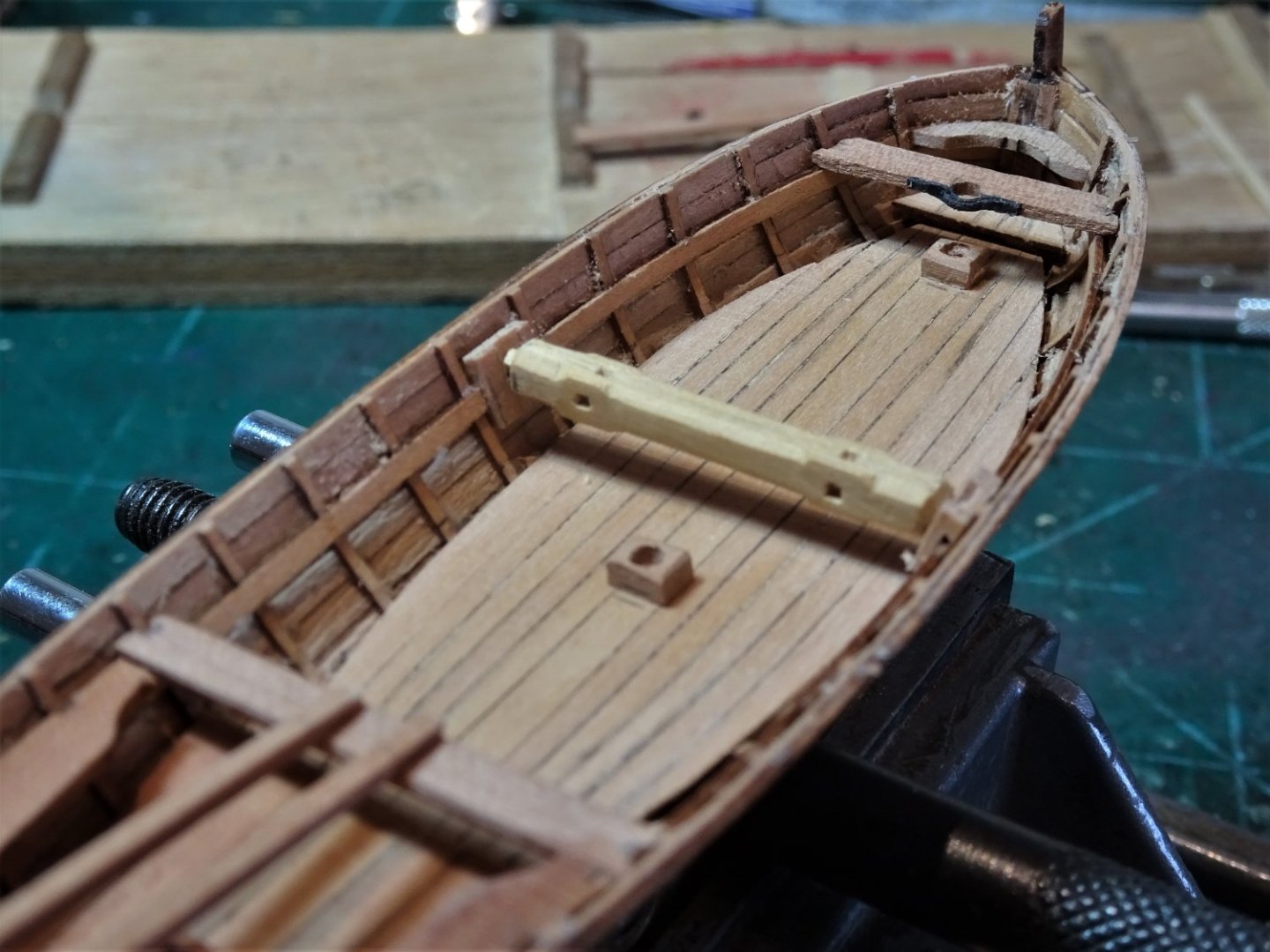
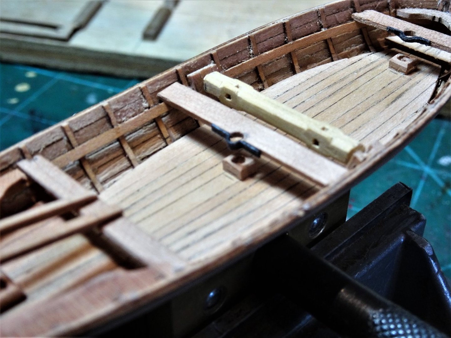
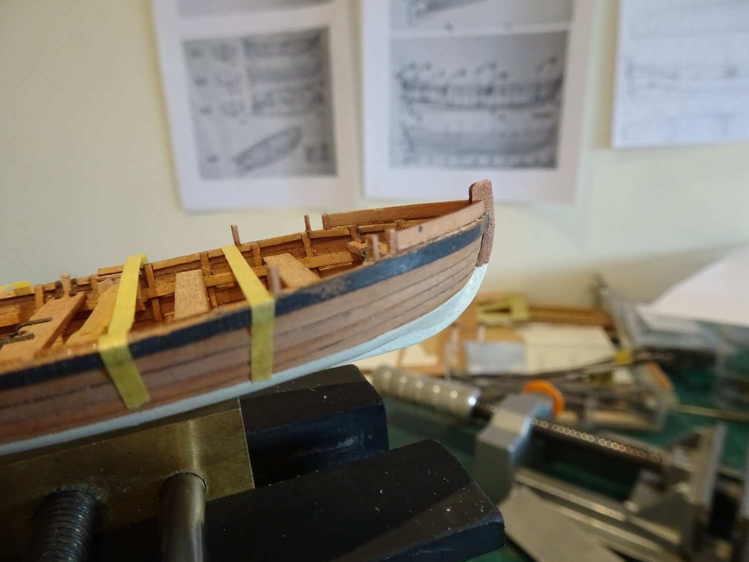
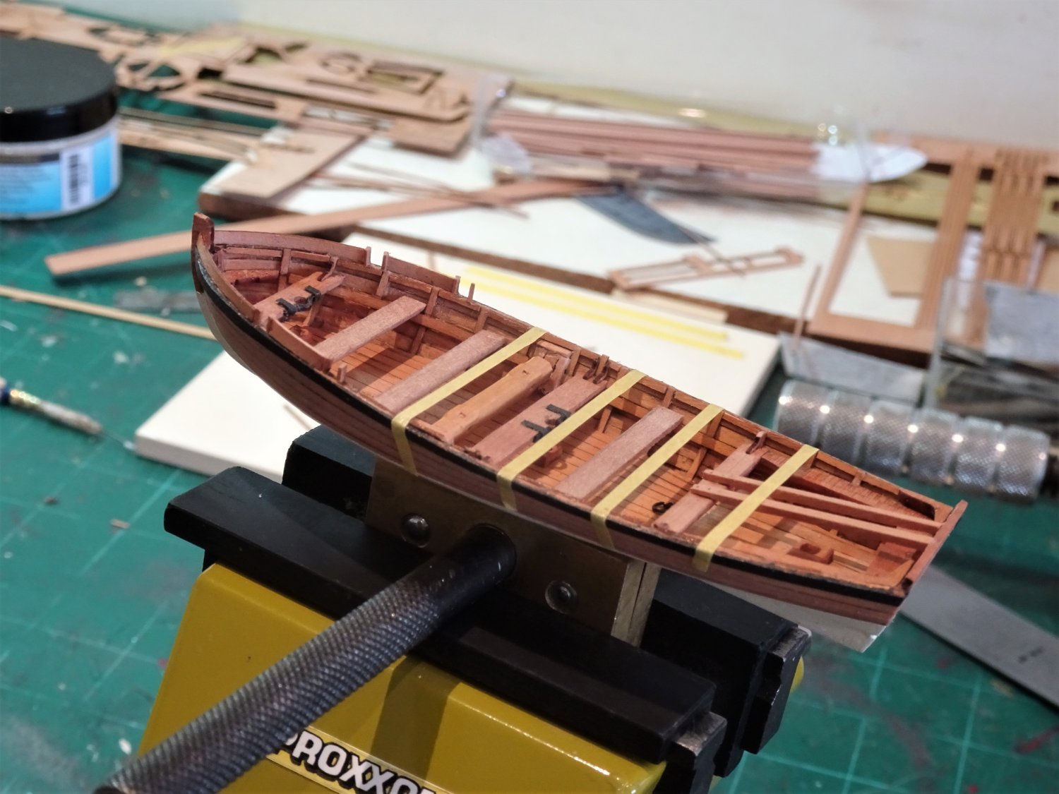
Post One hundred and Sixty. The Launch – ongoing Detailing continues; the thwarts are in place along with the Windlass. The lifting rings have been added to the keelson. 8220 Still to add the thwart brackets. Fitting the brackets is an exercise in frustration; they are incredibly tiny items, seemingly smaller than those for either the Pinnace or Yawl. The only saving grace is that brackets are required for only three of the thwarts, which allows a margin for the inevitable escapees. Before I move onto the wash strakes I needed to decide whether to paint the bottom of the launch up to the waterline. 8221 I had intended to leave the whole hull bright across the range, but I quite liked the effect on the Pinnace, so ivory bottom it is. On the kit the hull is painted white overall up to the wale, but I prefer a bright hull between waterline and wale which provides a nice contrast. Wash-strakes These are formed using planking strips allowing for the oarlock spaces. The blurb says add more lengths of planking along the bulwark top for the oar positions. Easy to say, not so easy perhaps to achieve. There is nothing to support these thin strips and they should follow uniformly the curve of the hull. The kit arrangement is a simplification, presumably due to scale. In reality there would be tholes to secure and take the pressure of the oars, and against which the temporary wash boards would be secured. 8224 To try and add a tad more realism to the set up I fitted strips between the frames along the inner hull to support the tholes. Admittedly I am doing this as an exercise to see if I can, and it does extend the build time which means I don’t have to think about another one.🙄 The thole positions are marked and the process can begin. 8234 The wash strakes at the Bow are attended to first, these are heat treated to follow the hull before fitting against the first thole. 8244 With that done the next thole can be fitted with a 1.25mm spacing, and so on. 8241 8250 I will continue to fit the wash boards and hope it all turns out ok. The danger will be when I come to clean it all up, whether these delicate pieces will hold in place. B.E. 27/08/2022


- 857 replies
-
- 13
-
-
- Sphinx
- Vanguard Models
- (and 1 more)
-
Post One hundred and fifty-nine. The Windlass This is a tricky fitting to make, the actual length of the Windlass is a mere 28.4mm which has to contain both square and octagonal sections. Steel records the Windlass for a 24’ Launch as being of 8”ø which equates to 3.2mm at scale. I will be using 3mm Boxwood Square stock for the makings. How to begin. When in doubt refer to Chuck; Chapter four of his Medway Longboat Monograph explains the process and fortunately I have his wonderful Medway Longboat at ½” scale, and in the plans is a template for making a windlass. 8184(2) Reduced to 1:64 scale it provides a guide that should prove very useful, provided my eyesight is up to the job. I have made windlasses at 1:48 and 1:64 scales previously but that was some years ago. The templates are glued to the faces of the square stock and it’s then down to how well the octagons can be formed. 8186(2) The stock is supported in a simple ‘V’ jig. 8187(2) I use No11 scalpel blades and micro chisels to form the octagons. 8190(2) I use the No11 scalpel blade to form the rebate. 8195(2) The template certainly simplifies shaping the windlass particularly at this scale, as marking with pencil lines is not so easy on this small area. With the template removed a little more definition is given the the octagonal areas, and the ends formed. 8198 Trial fitting of the windlass into the support chocks. 8201 The Main Thwart is checked against the Windlass position. The remaining thwarts can now be made and put into place. A final thought, given that the windlass is an important feature of both Longboats and Launches, I think a resin version of the Windlass would be a good ‘optional’ fitting for the Vanguard Launch kit. B.E. 25/08/2022
.thumb.JPG.f2cb06c6c8e0ea71dc8a676bd2295a1e.JPG)
.thumb.JPG.66a61fde9750ae9c3dad91bf9dba49e7.JPG)
.thumb.JPG.b11f763e36e56f723bc6e12c5a412536.JPG)
.thumb.JPG.3892433e31cd8c9d553efd6aa9c8429c.JPG)
.thumb.JPG.72ed9cb0efadc9a308c5c756afd023b0.JPG)
- 857 replies
-
- 16
-
-
- Sphinx
- Vanguard Models
- (and 1 more)
-
Thank you Kevin, not so lovely just yet, a fair bit of fettlin' to go, but I too love these bijou models, hours of fun at a modest cost, and a challenge thrown in. What more could you want.😀 B.E.
- 857 replies
-
- 3
-
-
- Sphinx
- Vanguard Models
- (and 1 more)
-
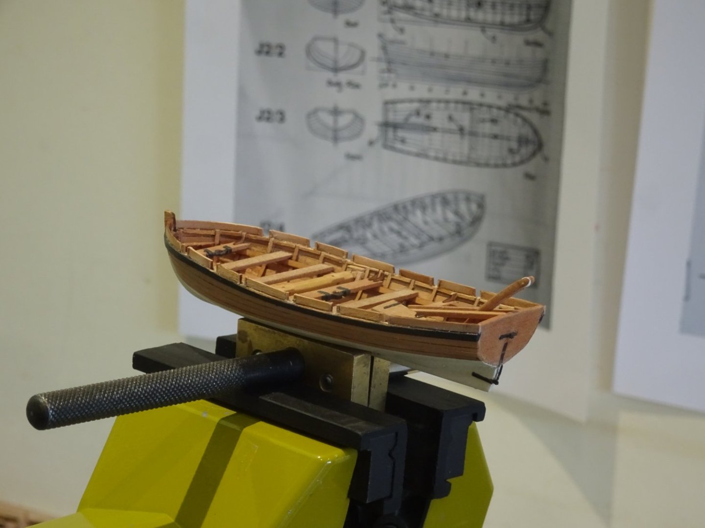
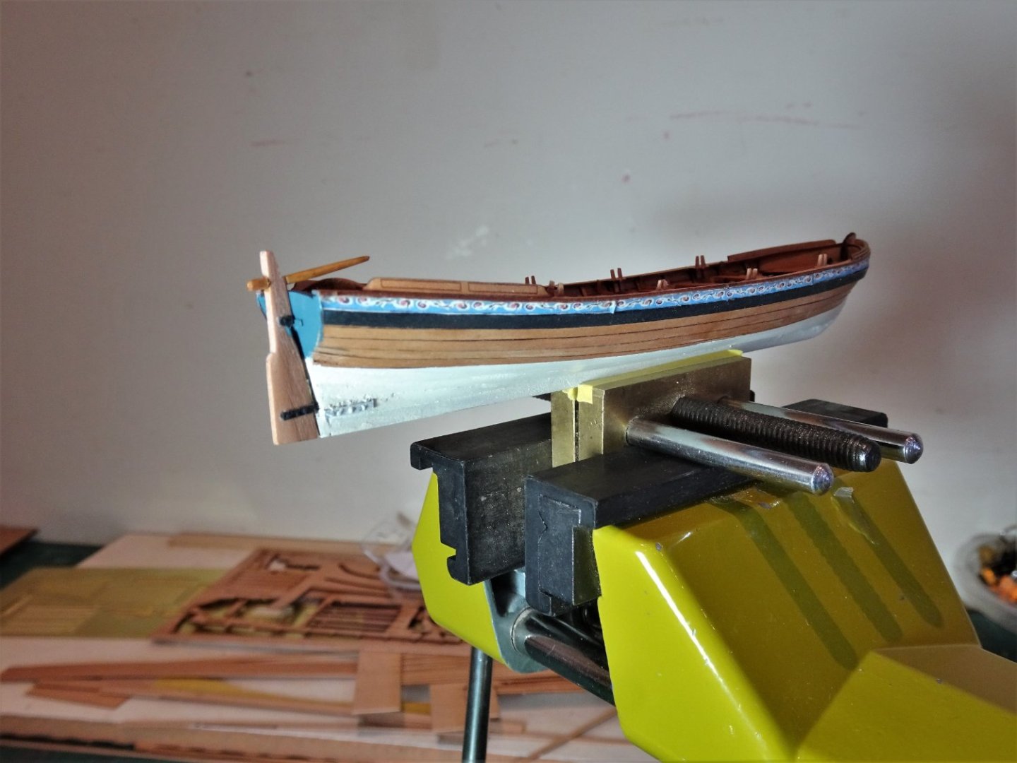
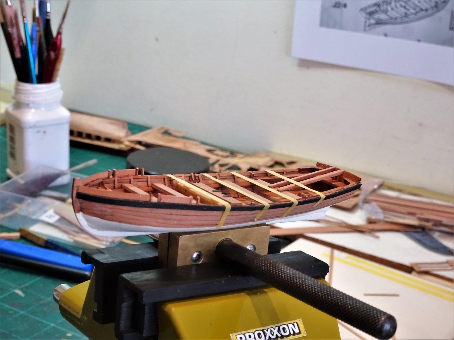
Post One hundred and fifty-nine. The Launch – cont’d Fitting the stern sheets The kit provided part includes the stern-sheets and adjacent thwart as one unit. There is no bench on the aft side against the transom. Victory Launch - note the dis-mounted Davit This may be a design feature to allow easier fitting, which it does, but I am aware that the current launch with HMS Victory also has no transom bench. I chose to include a Transom bench between the two side benches, as per the drawings in the AotS books, Pandora and Diana. 8173(2) The individual seating parts were split up and the cut-away shape common in side benches, was formed. The Davit The kit provided Davit is of a simplified form lacking the sheave in the outer end. I also thought it looked a little under weight. The Davit was used to support the handling of anchors I doubled up on the kit pattern to create a sheave in the outer end, this gave an overall width of 2mm. 8177(3) The Davit supports were re-made using 1.5mm square stuff, I also re-made the thwart adjacent to the stern-sheets, onto which the Davit supports are bolted. 8168 The Breasthook is fitted at the bow along with the first thwart. The remainder will be left until the Windlass is fitted. I made the Fore mast clamp on the thwart with black card rather than use the provided etch. 8170(2) This is also an opportune time to add the wales which further strengthen the hull for handling. More work is required cleaning up the inner hull, these macro shot fill me with horror.😬 I prefer scraping with a wetted sharp blade rather than sanding, the thinness of the planking always has to be borne in mind. 8177(2) The mast steps have been fitted and the Main Thwart made. This is wider by an inch than the other thwarts at 10” (4mm) Before moving on, there is a windlass to make, an interesting little exercise. B.E. 24/08/2022
.jpg.15e8759b6a3c27627c1fb1bac7158e36.jpg)
.thumb.JPG.6ca1e0375ed08c96affad859a3d6b92f.JPG)
.thumb.JPG.5cc8f85e1ad3e0a83ab63ef4b87775cc.JPG)
.thumb.JPG.134680060242da8cd9566259e6087ede.JPG)
.thumb.JPG.314913811a1a58f0eb6dbc1e8dddc1b6.JPG)
- 857 replies
-
- 19
-
-
- Sphinx
- Vanguard Models
- (and 1 more)
-
I like the round pedestal table Chris, any thoughts of creating a seated figure to grace it? B.E.
-
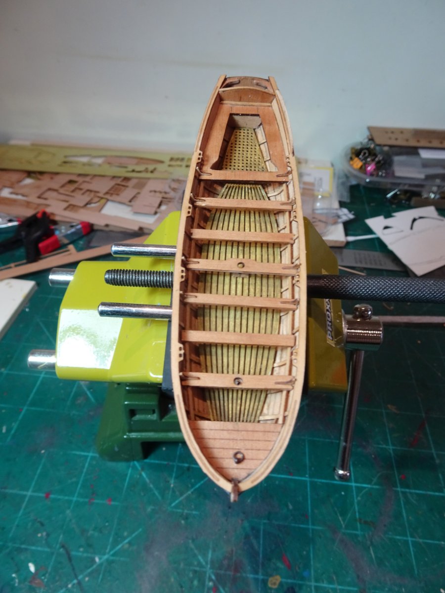
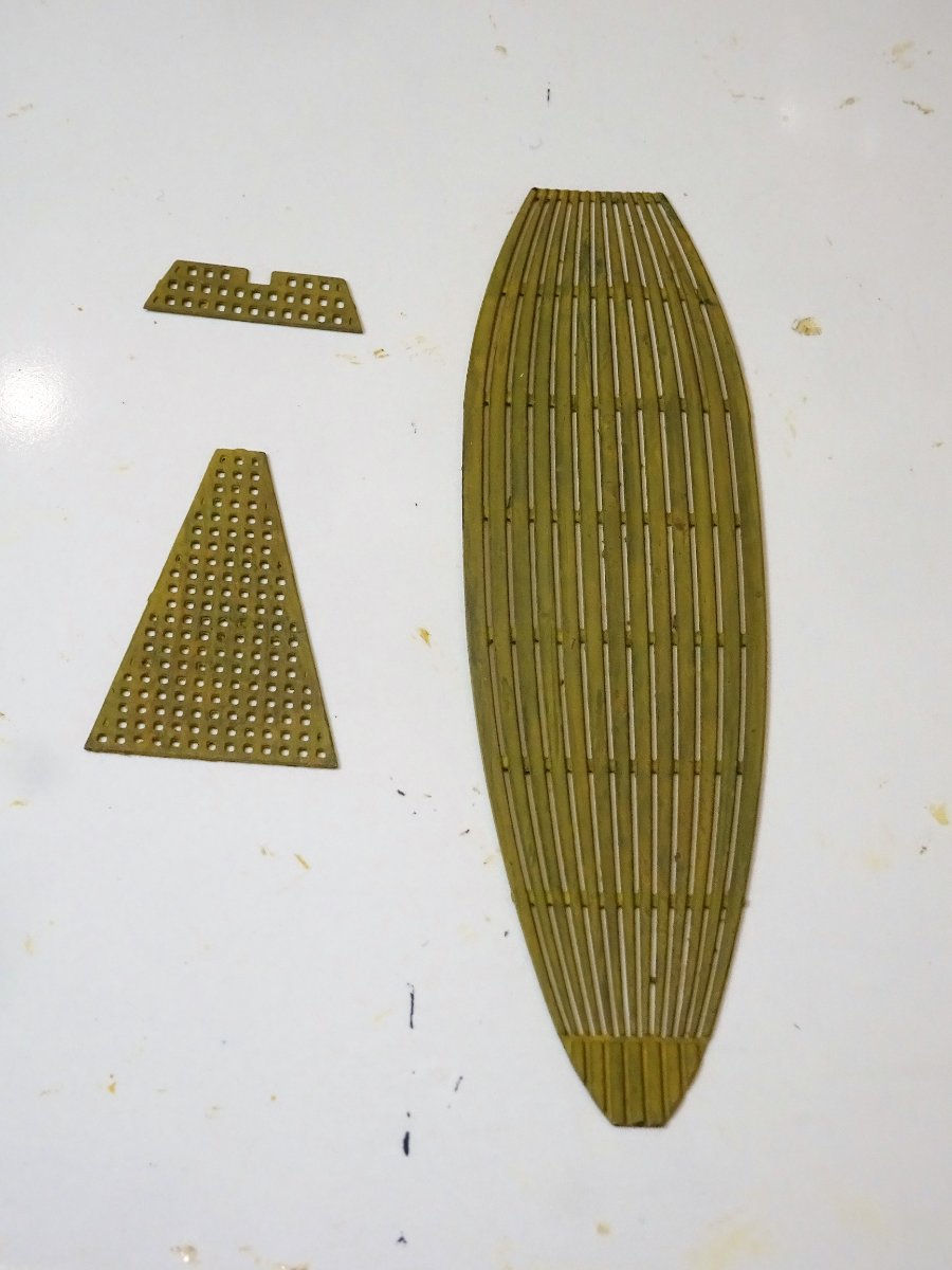
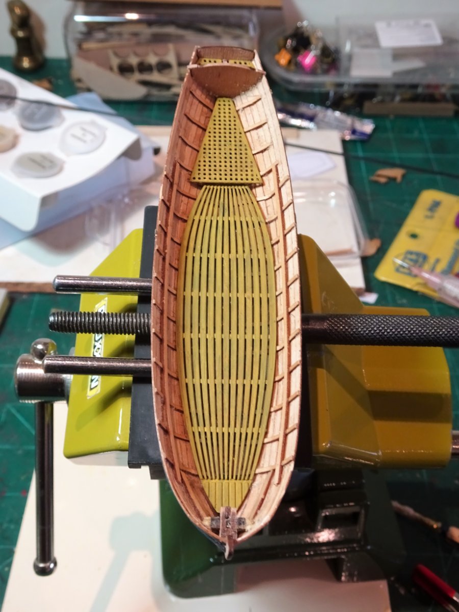
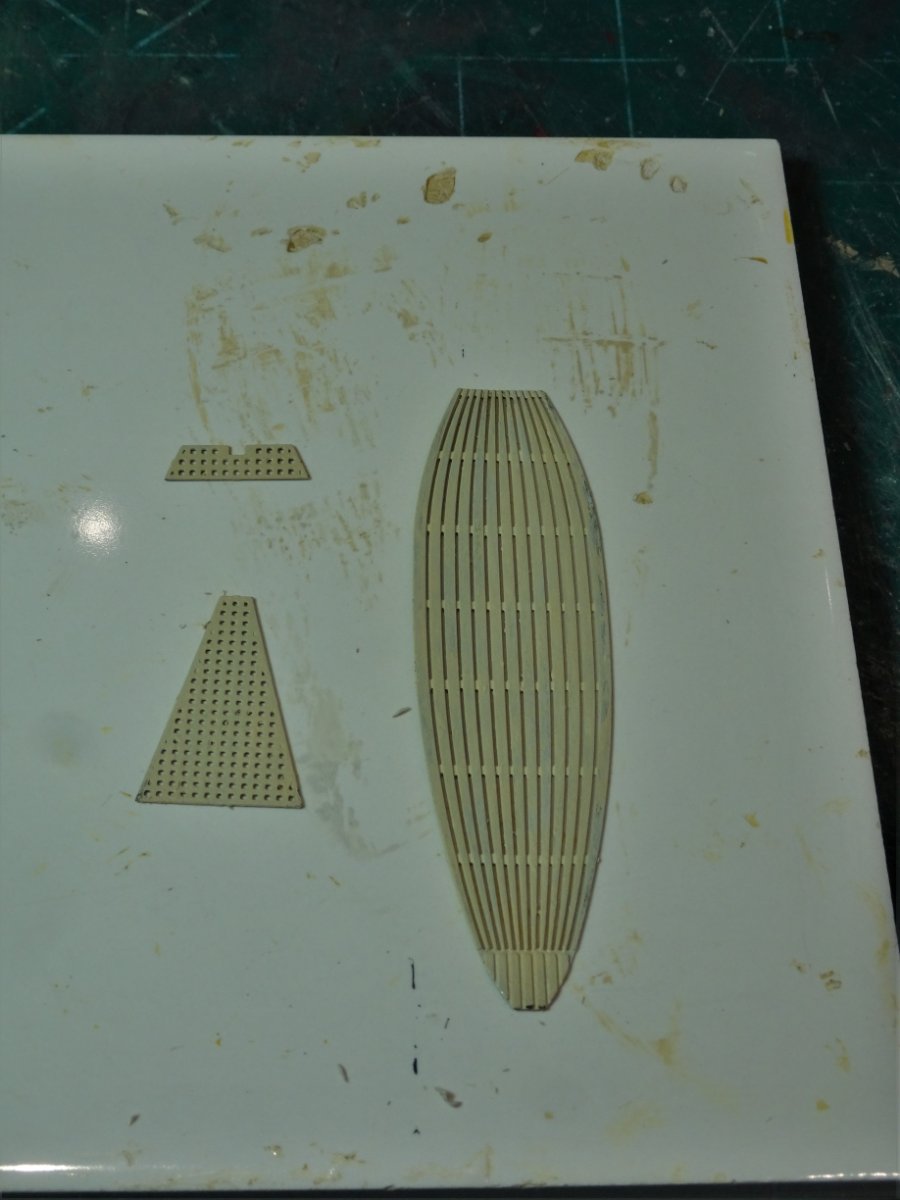
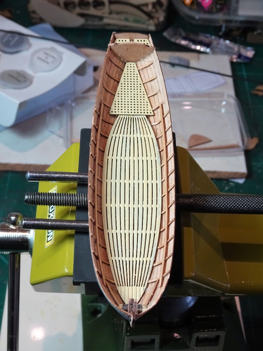
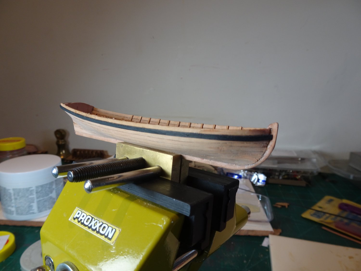
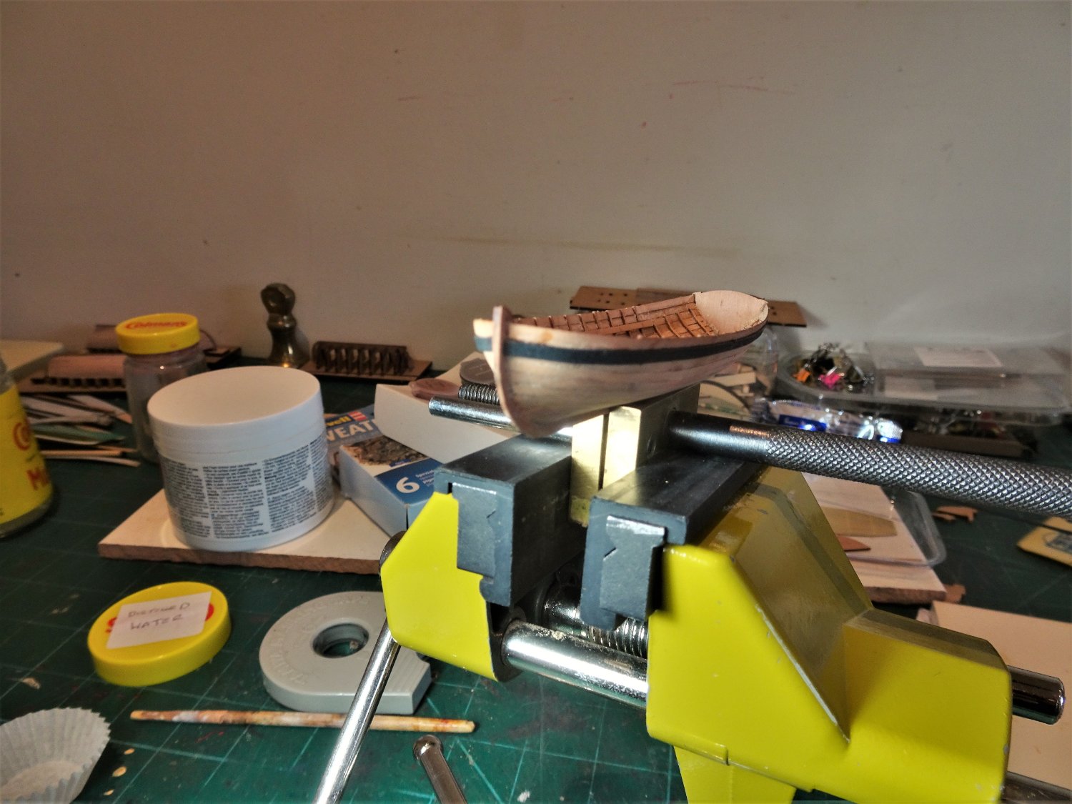
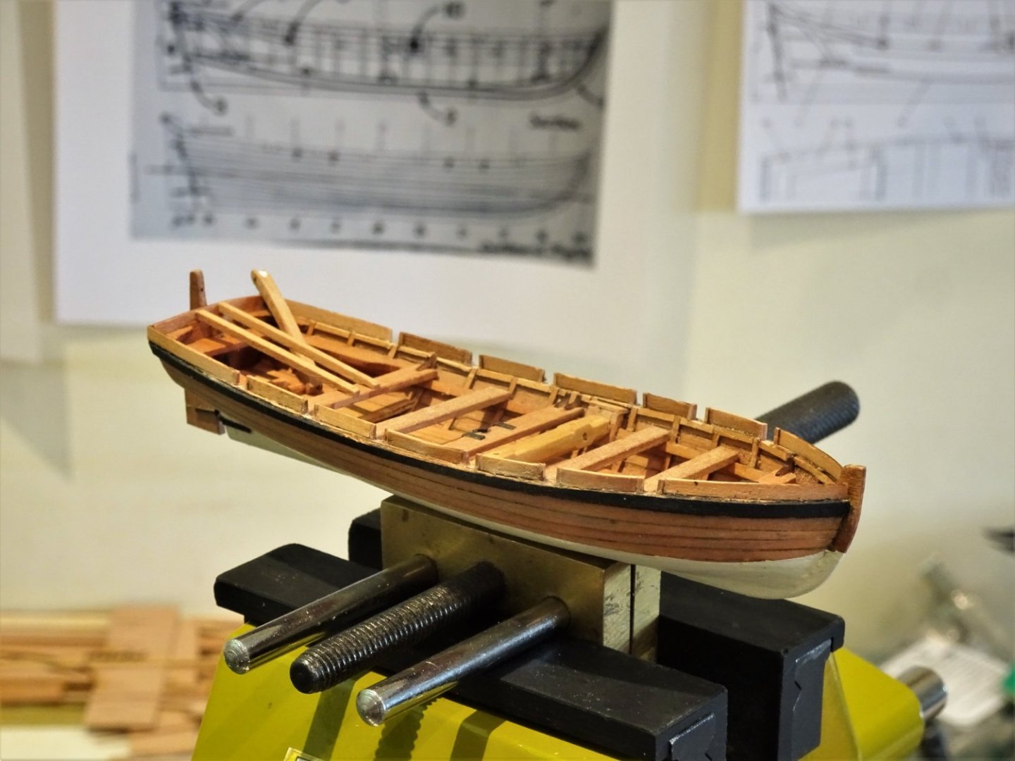
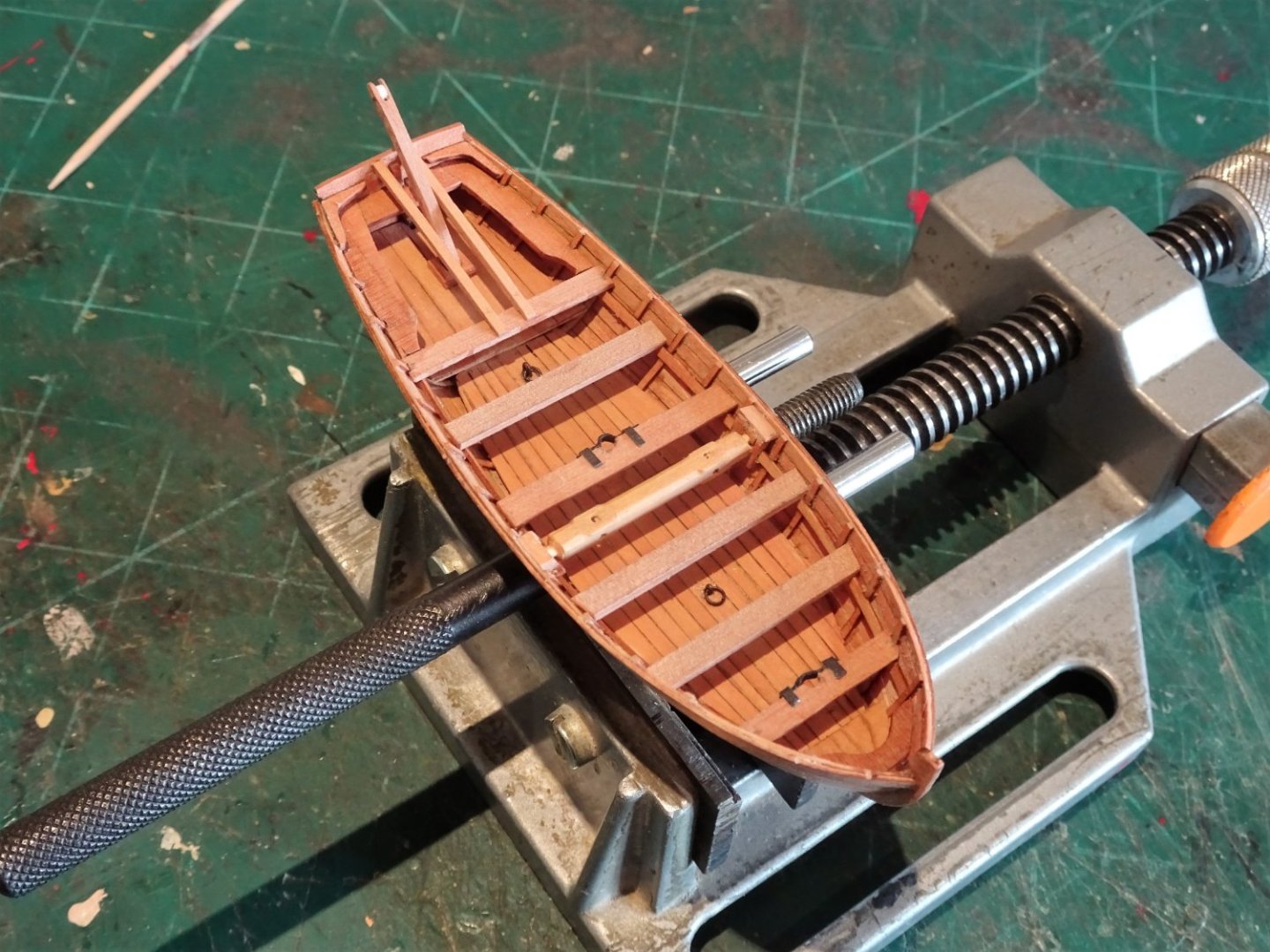
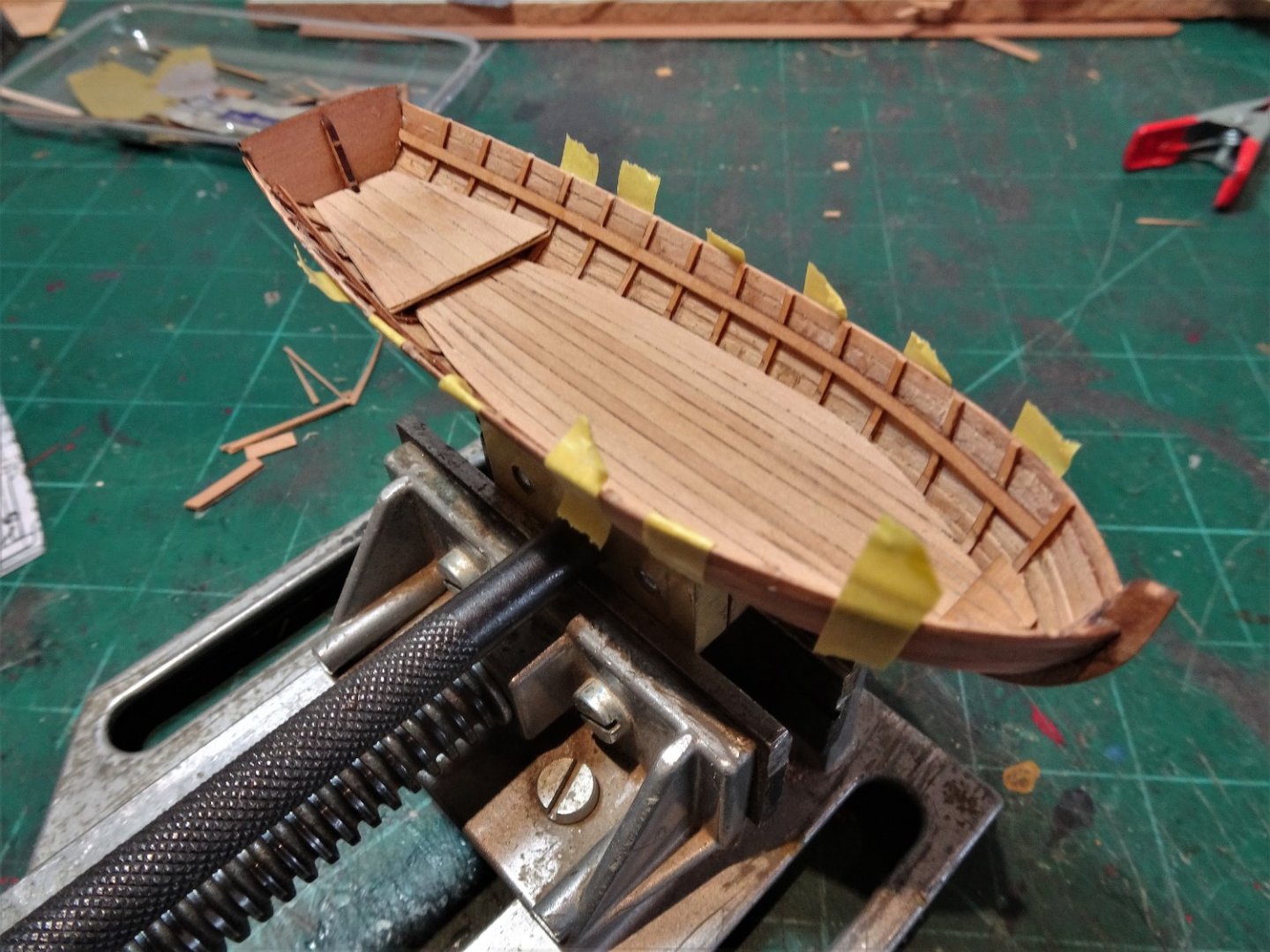
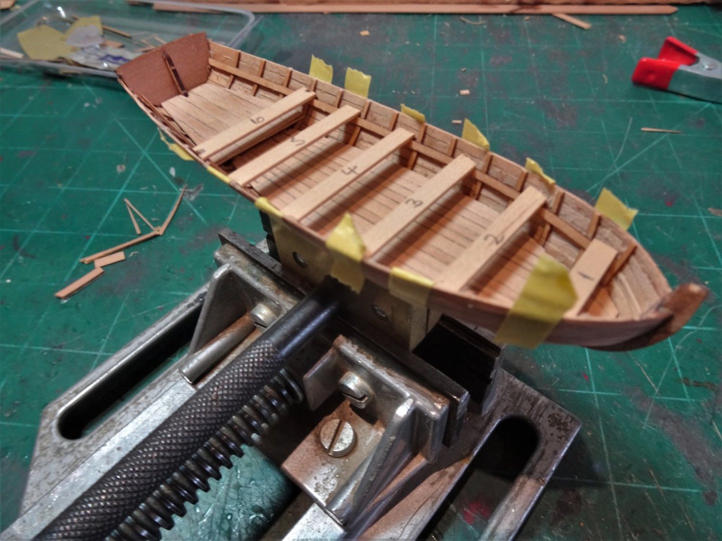
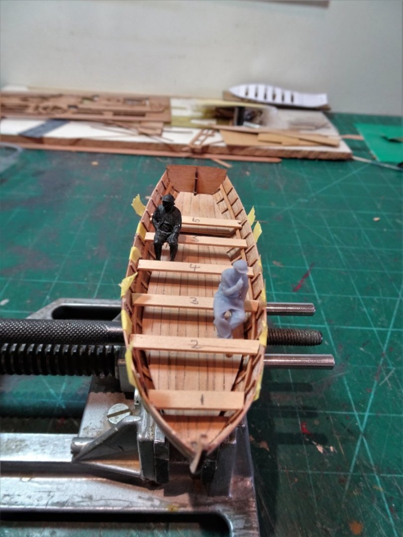
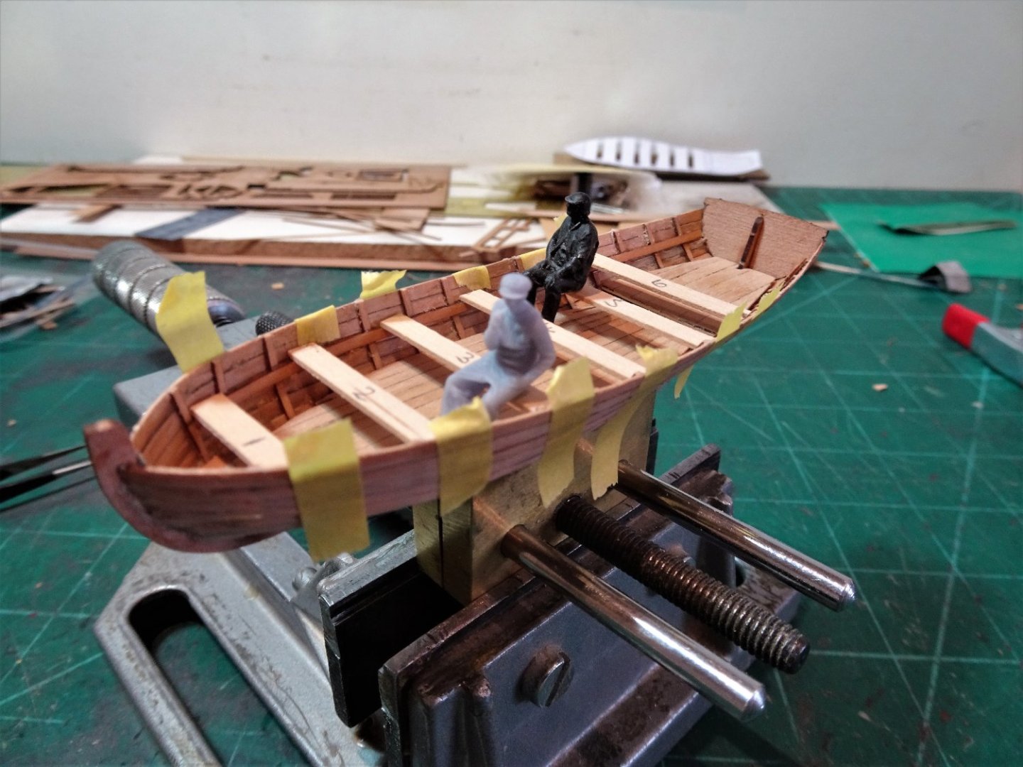
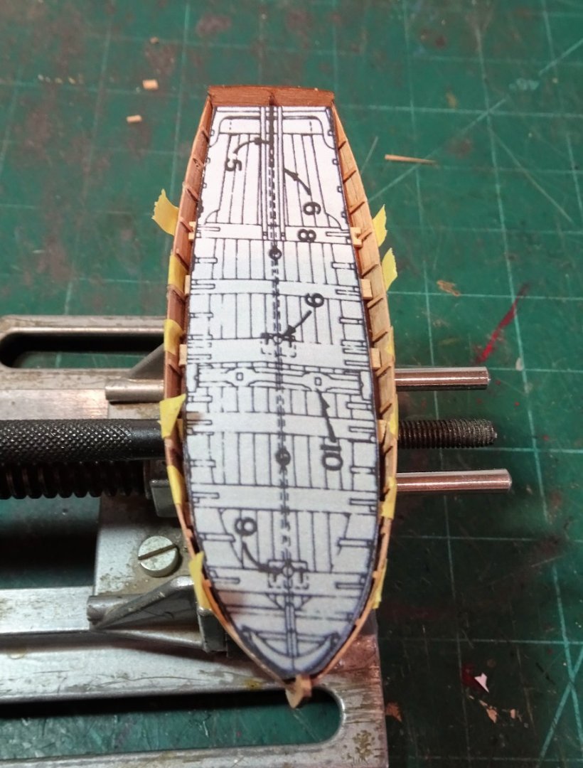
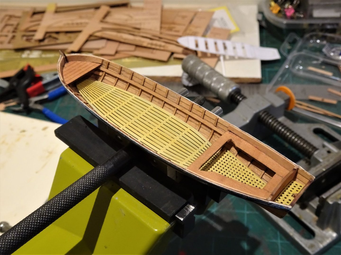
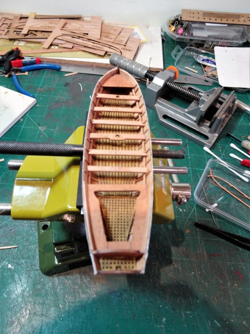
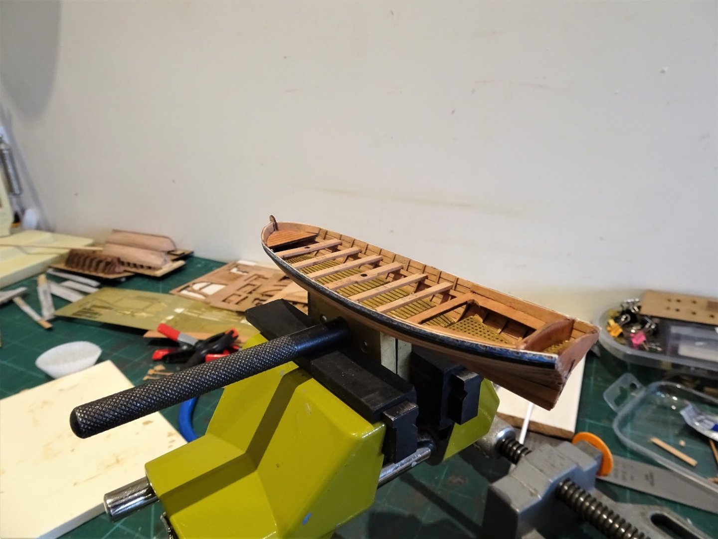
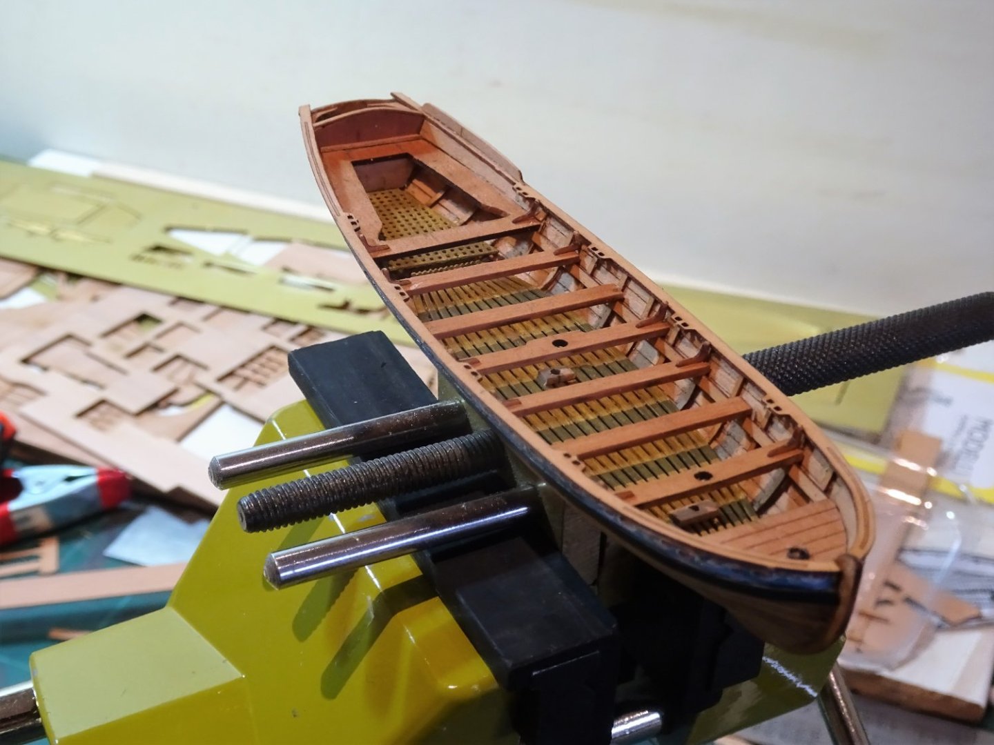
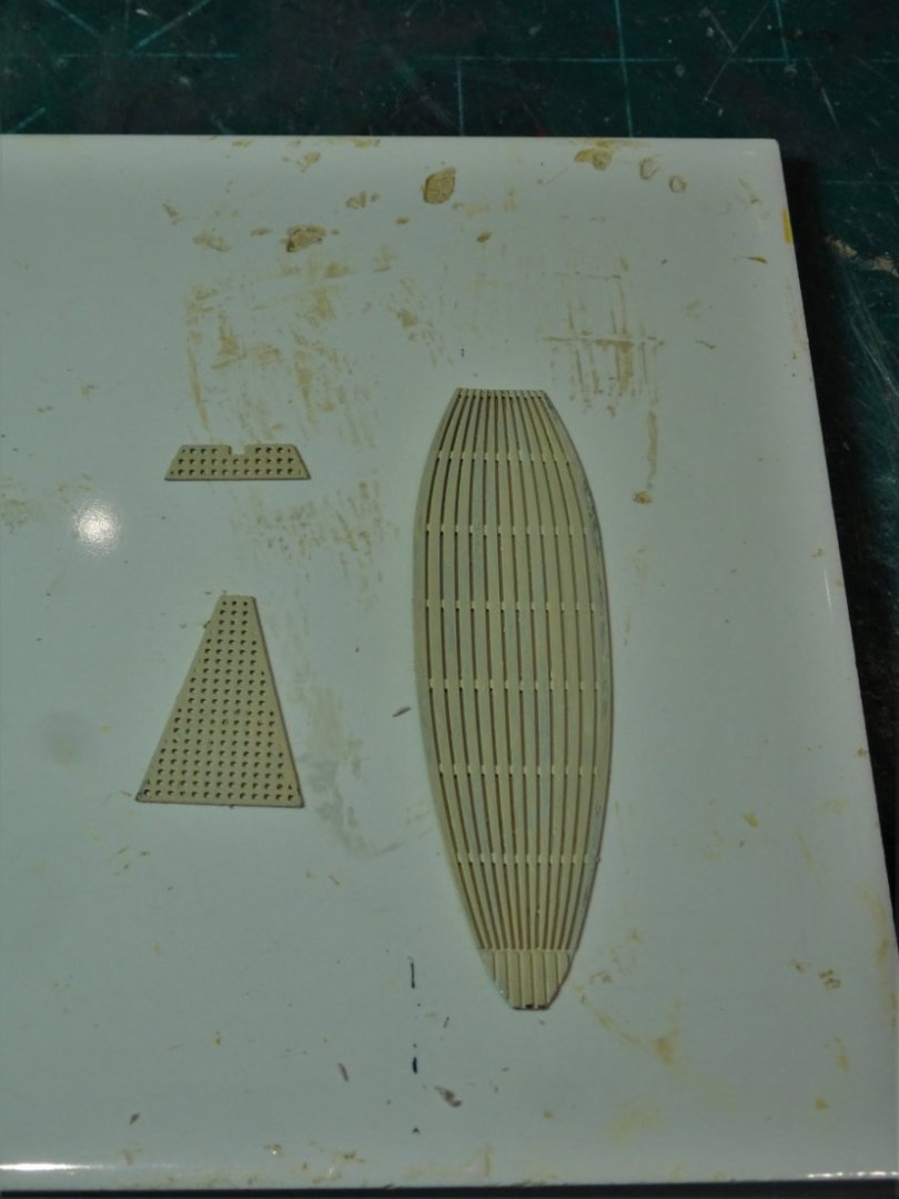
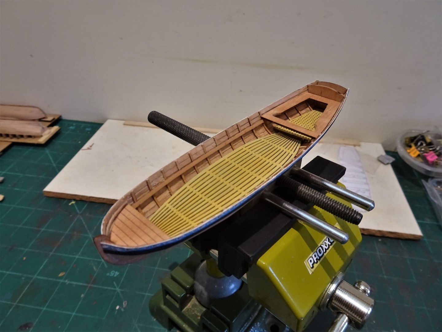
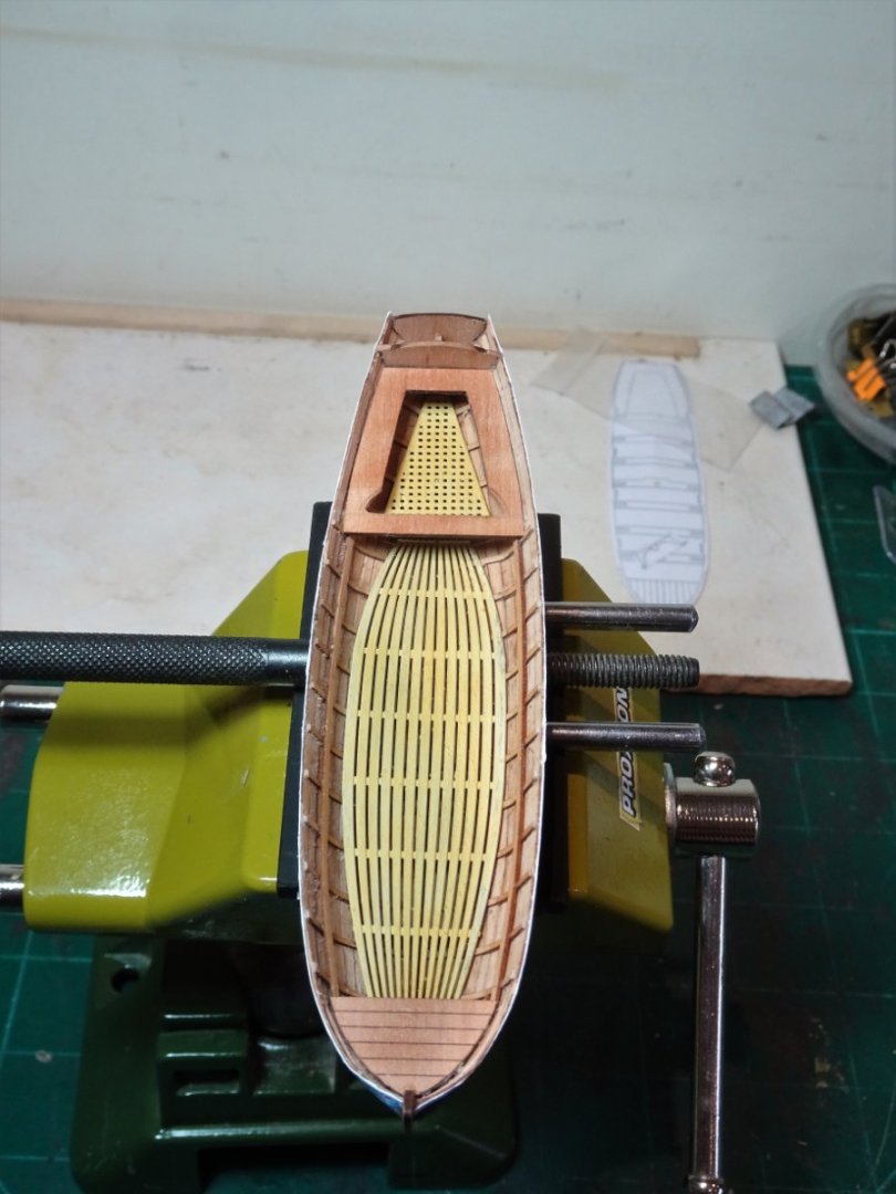
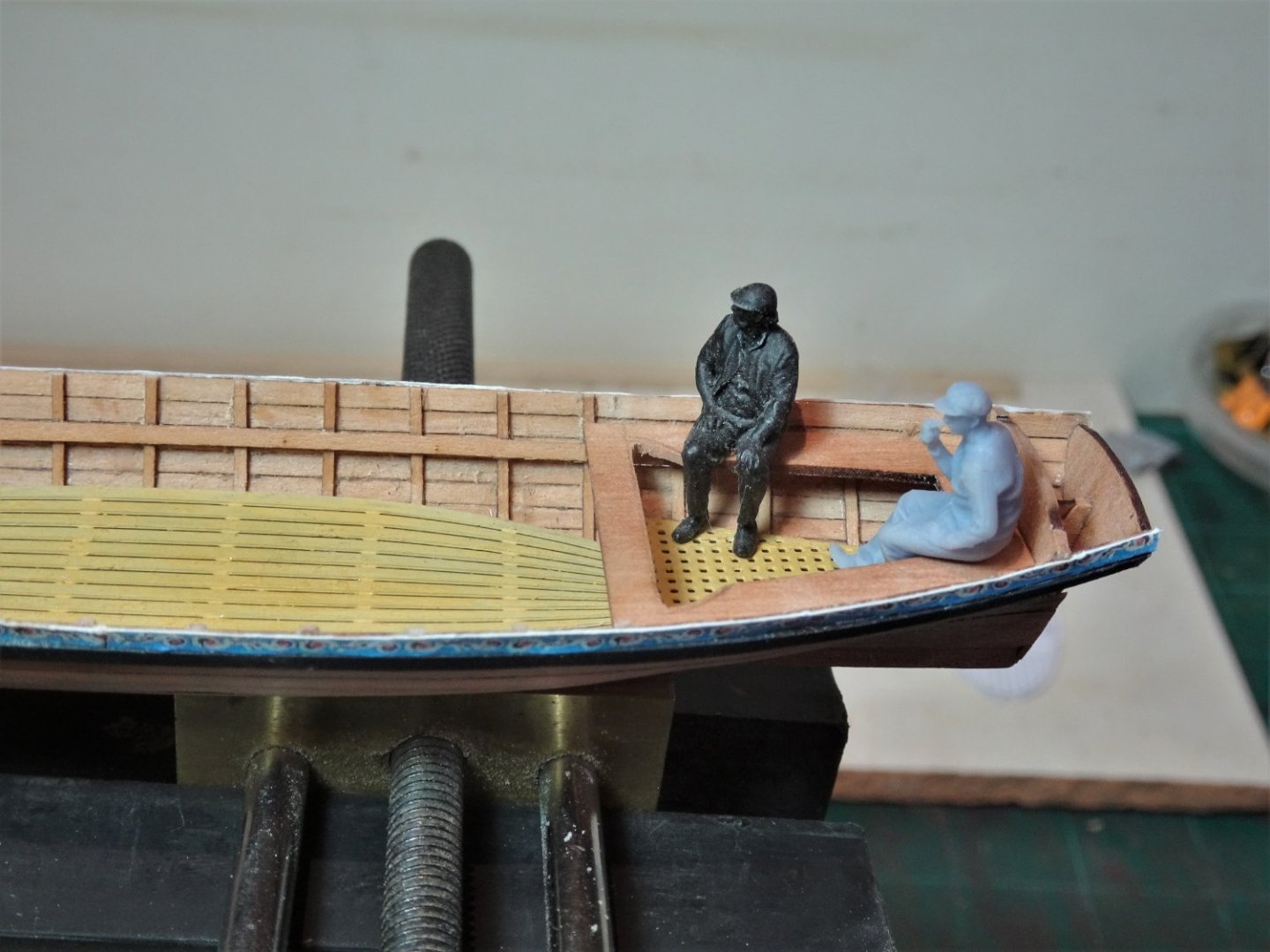
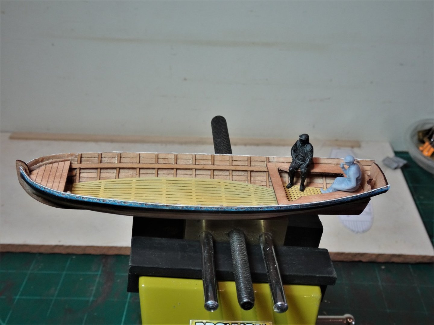
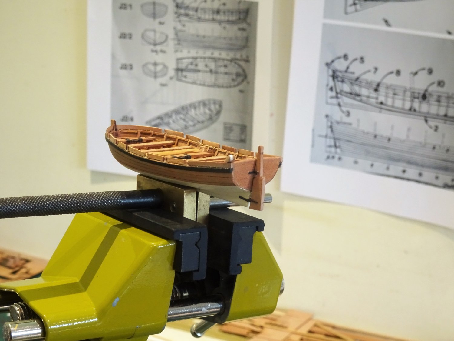
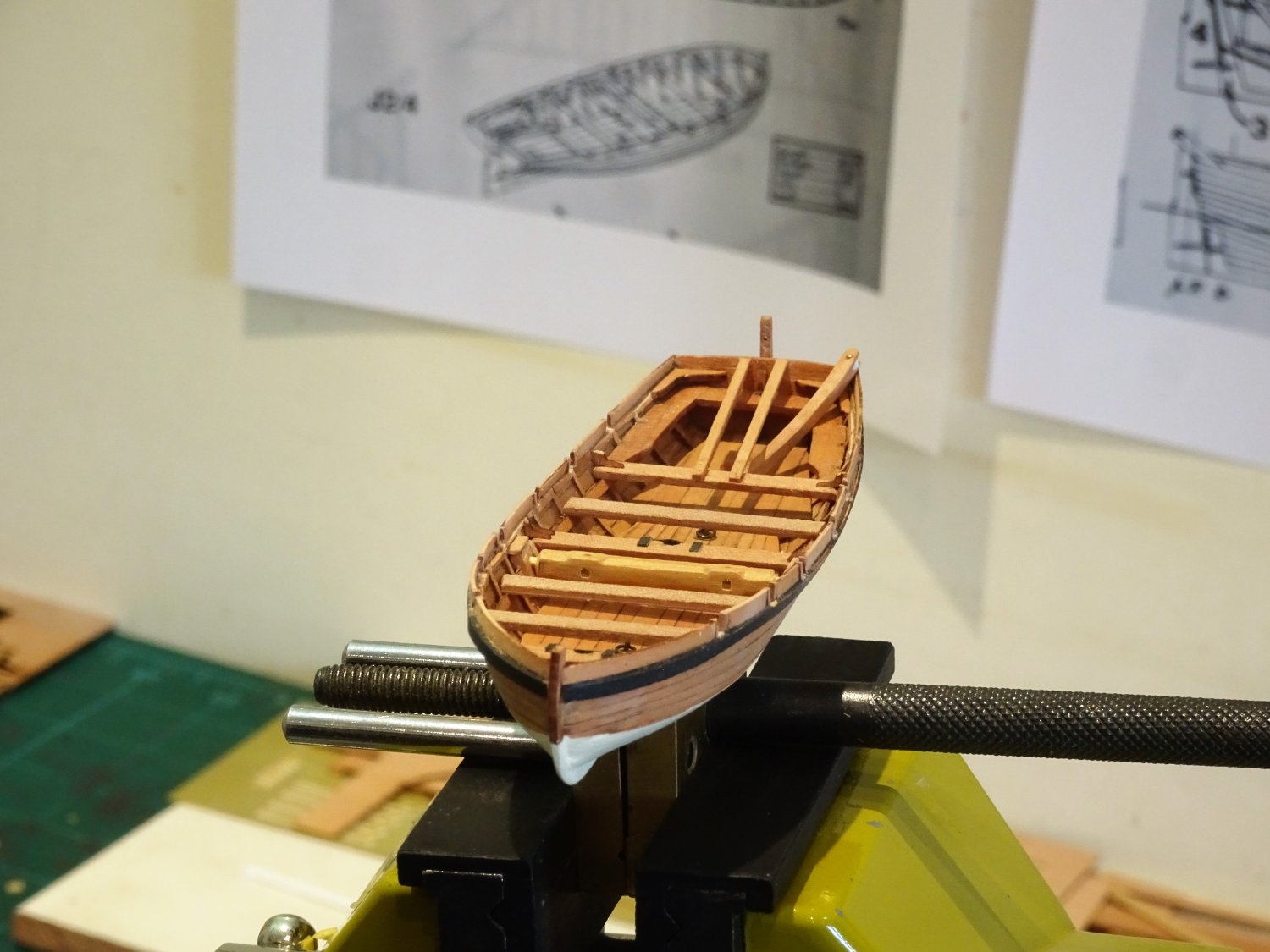
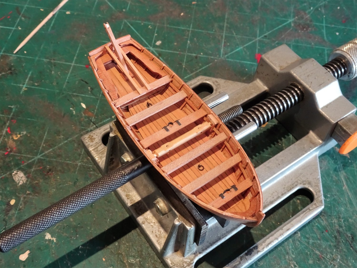
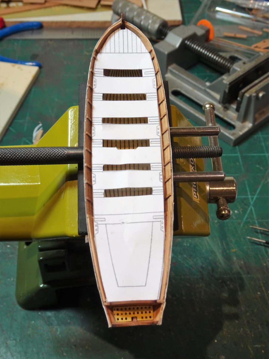
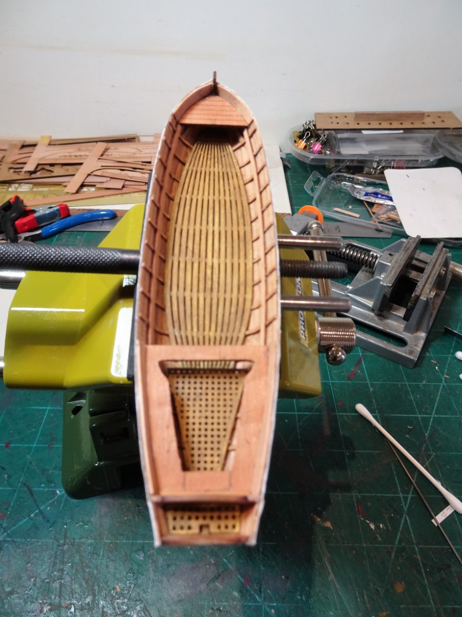
Post One hundred and fifty-eight. Building the Launch This is the heavy work boat of the set. Lacking the elegance of the Pinnace it does have interest to commend it and I’m looking forward to having a go. The kit includes a simplified davit and its supports, but for some reason is lacking the windlass which is the other important feature of Launches, as it was with the Longboat. I compared the kit launch with the drawings in the Pandora book for a 24’ Launch. The book drawing does indicate the windlass and has two less thwarts (including the stern sheet ) compared to the kit version. 8107 The stage after fitting the ribs provides the first opportunity for revision. The kit provides a brass etch version of the keelson and footwaling which I thought was perfect for replacement with a more authentic boarding. The kit also provides brass etch gratings for the stern-sheet and bow areas. Looking at Launch plans and those for Longboats, gratings did not seem to feature on these boats, and it makes sense that the stern-sheet footwaling was solid to form a stable base for the Davit step. 8110 Replacement footwaling, which at least saves me the trouble of trying to turn brass into wood. 8109 The Keelson is a slightly wider and thicker board that runs down the centre of the footwaling to support the mast steps and lifting rings. The number of thwarts in the kit version is eight including the the one adjoining the stern-sheets. 8119 I am using the design for a 24’ launch in the AotS book Pandora. 8120 I will be using six thwarts which allows for a slightly wider main thwart at midships, and provides room for the windlass. 8111 With the stringers in place temporary thwarts are used to get things ship-shape. 8114 Once again my dockyard figures ensure the thwarts sit level and at the correct height, don’t want their feet dangling in mid-air. 8118 I still get a satisfaction seeing tiny feet planted on the footwaling, all down to Chris’s excellent scaling of the boats. Still a fair bit of fettlin’ to do and a Windlass to make. B.E. 22/08/2022


- 857 replies
-
- 15
-
-
- Sphinx
- Vanguard Models
- (and 1 more)
-
It's certainly not elitist to advance knowledge of our subject. I accept the limitations of kits, they have to appeal to a large range of potential buyers, don’t frighten the novices, or unduly lack credibility with the experienced, whilst maintaining a reasonable cost/benefit ratio of producing the kits. Chris does wonderfully well to authentically represent the majority of the subject detail, but it was the tweakability of Sphinx that appealed to me. I record the modifications and changes I make in my builds partly on the basis that not everyone has access to the very large reference library I have built up over the years, and giving such detail gives options. Of course many people just want to complete a nice looking kit, and that’s just fine. Unlike myself not everyone has or wants a head stuffed full of 18th c trivia such as: Worm and parcel with the lay, turn and serve the other way. Mrs W definitely thinks I’m weird, but she indulges me in what in the overall scheme of things is a minority interest passion. Movin’ on B.E.
- 857 replies
-
- 8
-
-
- Sphinx
- Vanguard Models
- (and 1 more)
-
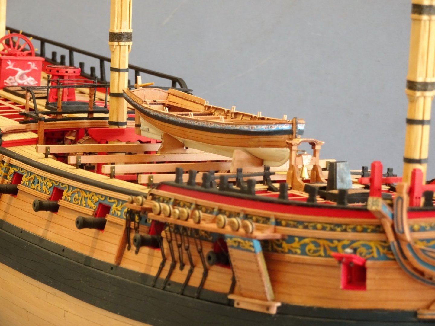
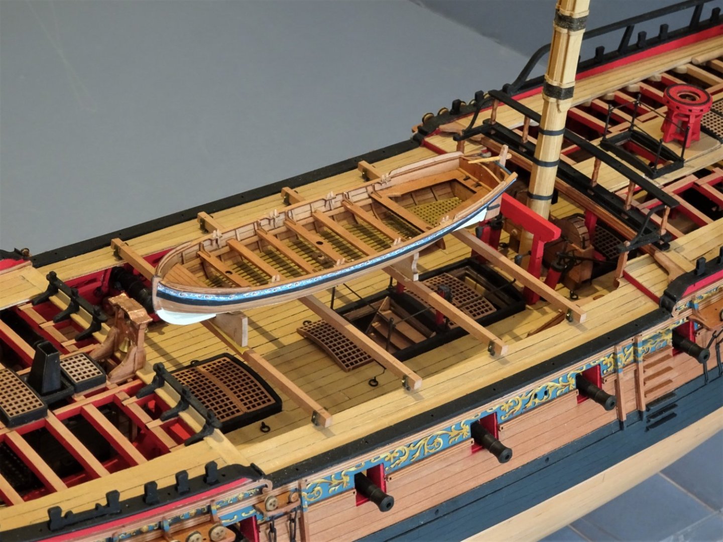
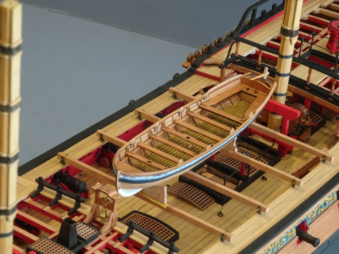
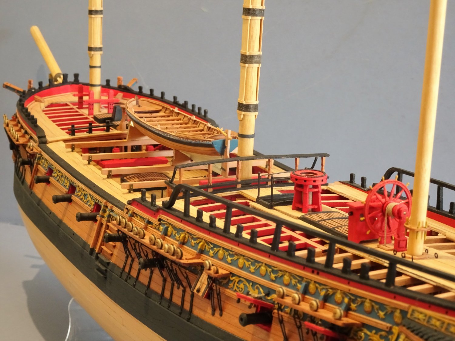
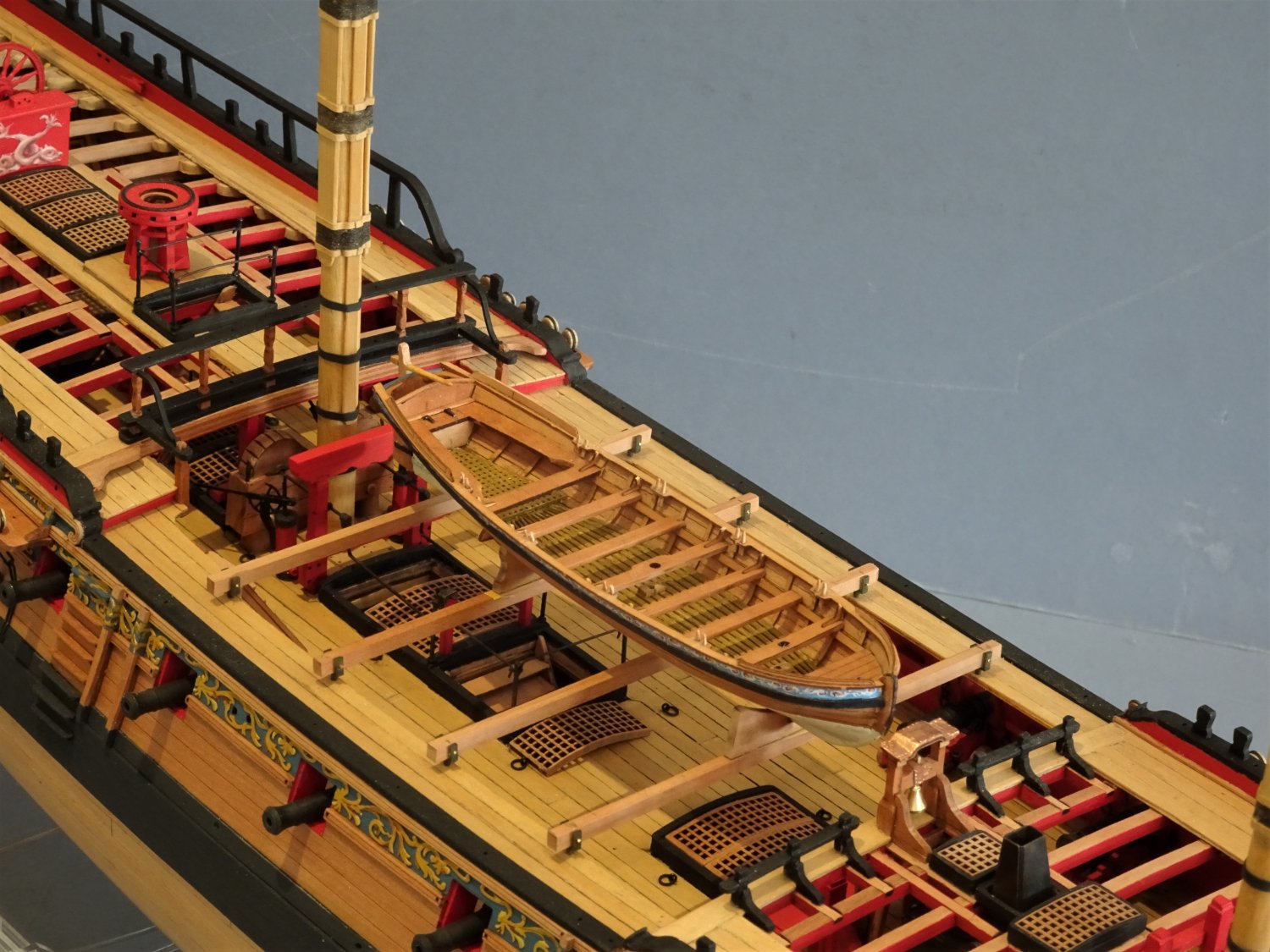
Post One Hundred and fifty-seven A place on the skids? Well my curiosity got the better of me and I just had to try the Pinnace onboard Sphinx. This coincidentally is the twelve month stage from starting the build. I’m warming to the look of the Pinnace on the skids and it doesn’t obscure the upper deck detail. 8090 8092 8086 8085 8081 8075 8083(2) 8074(2) 8078(3) 8071(2) 8070(2) 8063(2) Nothing set in stone at this point, but I have decided that having all three boats on the skids would detract rather than enhance the look. For me, Georgian elegance is why so many contemporary 18thc models only show the Pinnace onboard, it is the most graceful and aesthetically pleasing(along with barges) of the boat complement. B.E. 20/08/2022
.thumb.JPG.771c8b32c0351f2a6c8d9646c918c252.JPG)
.thumb.JPG.e639972fe432641d2a2e0d2b1d686778.JPG)
.thumb.JPG.9532bedc616f47a0aac79ec7a3e95980.JPG)
.thumb.JPG.43e82434070c9832a7aa7235a9e4bbfc.JPG)

.thumb.JPG.46907168943efd606902a3612e22f711.JPG)

.thumb.JPG.df8b237f45307270c35d2b952cc87282.JPG)
- 857 replies
-
- 22
-
-

-

-
- Sphinx
- Vanguard Models
- (and 1 more)
-
That’s a sweet looking boat you have there, Allan. I would agree with your thoughts about the relative numbers and locations of the tholes. I think the kit designs have been influenced by the drawings in the AotS book Pandora by John McKay and Ron Coleman. The boat allocation is the same; 28’ Pinnace, 24’ Launch, and 22’ Yawl. Only the Launch is fitted for double banking on all thwarts, the Yawl is also set up for rowing on alternative thwarts. The boat drawings at 1:48 scale in the AotS book The Frigate Diana, by David White, seem to have the set-up correctly done. Had I been moved to replace the gunwales on the Pinnace I would have off-set the thole positions to reflect the single banking common to this boat type. To correct this on the kit one of the Gunwales would need a slight re-working. I say slight without any knowledge of the technical issues/costs involved in changing the kit parts, but the lack of off-setting was the first thing I noticed on the Pinnace. However, I suspect the finer points of single or double banking are lost on many kit builders, and even if recognised, are of less importance than just getting a nicely made boat, tricky enough with these bijou kits. Regards, B.E.
- 857 replies
-
- 4
-
-
- Sphinx
- Vanguard Models
- (and 1 more)
-
A reasonable assumption Glenn, stowed on deck all the vulnerable equipment would have been removed. Ps I don’t buy for one minute that you would make a mess of it, remember, I follow your logs.😉 B.E.
- 857 replies
-
- 3
-
-
- Sphinx
- Vanguard Models
- (and 1 more)
-
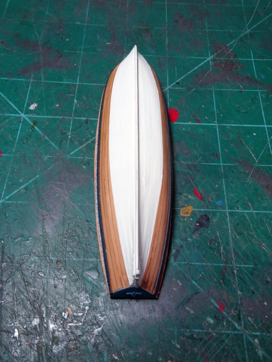
Post One Hundred and fifty-six Completing the Pinnace The final stretch for fitting out the Pinnace, seven days work and ongoing. 7996(2) The thole pins are brass etch of a devilish tiny size and are a loose fit within the mortices making it tricky to arrange correctly without getting glue on the woodwork. 7970(2) I chose to use wood slivers to represent the thole pins which I think look more natural, and they don’t need painting. 7973 The splash guards at the sternsheets and bow were pre-bent to remove stress and form the necessary curves. They were attached using pva. I had hoped to leave the Pinnace hull below the wale entirely bright, but my eye was less than satisfied with the hull planking finish around the lower hull at the bow. With some reluctance and not a little annoyance at my own deficiencies, I opted to paint the hull up to the waterline on the basis that a spot of ‘white’ stuff covers a multitude of sins. 7997 I used Vallejo Ivory paint which to my eye gives a better scale effect than white. 8022(2) 8030(2) As it happens I don’t think it has turned out too badly. The Rudder The kit design is a pearwood core sandwiched by thin brass etched patterns with the iron work detail moulded in. The rudder attaches with false gudgeons and straps. This certainly simplifies the process of rudder fitting, but for me it is a step too far removed from authenticity. 7994(2) Making a replacement rudder is fairly easy, but hanging working rudders on these small models presents something of a challenge. 8005 On the model a micro eyelet with 0.35mm ø brass wire silver soldered into it made for the lower pintle, and eyelets for the gudgeons. I laboured several hours to get the micro eyelets and pins in the right position. I used Syren fibreboard to represent the straps. 8051(2) One down, two more to go, I’ll set the Pinnace aside now and move onto the Launch. B.E. 19/08/2022
.thumb.JPG.dacc2144aa078b3e605fc91ae95c23eb.JPG)
.thumb.JPG.ee5024b8495e27540758fa8f4f2f02d8.JPG)
.thumb.JPG.918a60ebd3b2a71112e003a805f3f385.JPG)

.thumb.JPG.3305a1bf79a1d988435556cb03e0cff0.JPG)
.thumb.JPG.9ac8a6f093784e60f6695ba4d5841a9d.JPG)
.thumb.JPG.ac616d330fcb4561e19ebd22e20edb8b.JPG)
- 857 replies
-
- 17
-
-
-
- Sphinx
- Vanguard Models
- (and 1 more)
-
Hi Allan, I do have W.E. May book and back in the day I scratch built both the Pinnace and Longboat for my Pegasus build. A scroll saw was of great benefit cutting out the tiny frames. I am quite a lazy builder and if I can get a good aftermarket item rather than do it all myself I will, and tweak it a little if necessary. This option came about with the range of boats developed by Chris Watton, and at 1:64 scale I doubt I would ever scratch one again. B.E.
- 857 replies
-
- 3
-
-
- Sphinx
- Vanguard Models
- (and 1 more)
-
Impressive work Ron, great photos of the clue set-up, well done. B.E.
- 542 replies
-
- 1
-
-
- Sphinx
- Vanguard Models
- (and 3 more)
-
Thanks Allan, It’s a Cut-out from the plan. Well spotted about the ‘missing’ brackets. 👍The kit has brackets indicated for all the thwarts, but at least two of us know that wasn’t always the case. Regards B.E.
- 857 replies
-
- 3
-
-
- Sphinx
- Vanguard Models
- (and 1 more)
-
Thanks Glenn, They are tricky little beggars as you no doubt know, but the boats represent £85.00 of the cost of the kit, and besides I can’t resist the challenge. Fitting out is a time consuming business but there is a satisfaction to be had in achieving a half way decent finish, and I do like the look of a boat on a model ship. I’m not sure about all three sitting on the Sphinx skids on a Navy Board style build such as mine, but I will try the Pinnace out. Cheers, B.E.
- 857 replies
-
- 5
-
-
- Sphinx
- Vanguard Models
- (and 1 more)
-
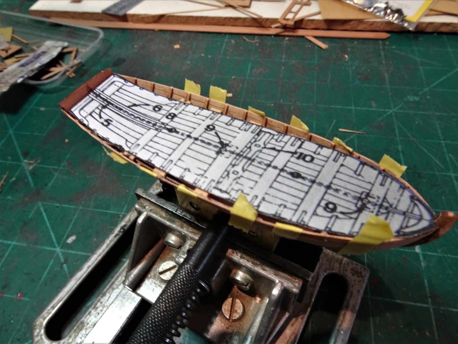
Post One Hundred and fify-five Fitting out the Pinnace – Part three As was the practise with Pinnaces I lined the sternsheet area and added a little extra detail. The bow deck area was also lined. 7935 Before the thwarts are added the inboard surfaces are treated with W-O-P 7936 Still not entirely happy with the decking colour against the thwarts, I dry brush using a mix of Ochre Brown and Burnt umber. The thwarts can be quite fiddly to fit, getting the lengths just right, ensuring they are all parallel to each other, and that the spacing is even. 7929 I use a plan template to assist this and cut temporary thwarts to determine the lengths. 7941 Temporary fit of the thwarts. 7939 I think the tone of the deck boards now looks better against the pearwood. With the thwarts fitted, the last major test is the Gunwales. These are very fine pieces and warrant careful handling. One small puzzlement for me is that Pinnaces were usually rowed single banked which means the oarlocks and thole pins were offset port and starboard relative to the thwarts. 7950 The kit version has them positioned for double banking. Any modification would require re-making the gunwales which I doubt I could achieve with the fineness of scale of the laser cut kit parts. 7956 Fitting the Gunwales is a tricky business, I dampened the bow ends to slightly modify the curve to suit the model, and I used ca to progressively glue the strip along the hull. 7944(2) As a pre-caution I did make a template of the gunwales lest sod’s law came into play and I was forced into scratching replacements. Despite my fears the gunwales went on without a sharp rise in my tension level. The next post should see the completion of the Pinnace. B.E. 18/08/22


.thumb.JPG.dff958acb9591dd807aa82be8ceec6da.JPG)

- 857 replies
-
- 19
-
-
-
- Sphinx
- Vanguard Models
- (and 1 more)
-
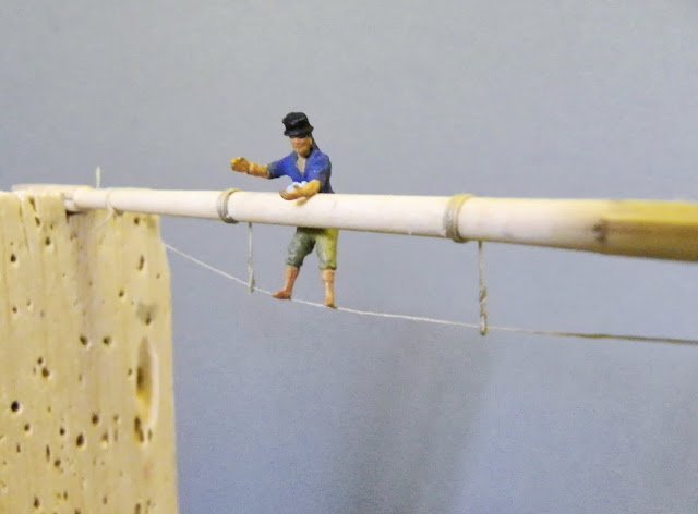
Thank you Thomas and Ron. @ Ron - I use scale figures for all sort of things, thwart height as above, but one of my most useful is old Tom who checks my footrope drop and is also very adept at Ratline scrambling. Not that he's needed on my current build. Cheers, B.E.
- 857 replies
-
- 8
-
-
- Sphinx
- Vanguard Models
- (and 1 more)
-
Hi Ron, Re rigging the Ensign to the Ensign staff. In a seascape setting under sail I think the Ensign would be worn at the Gaff from the Ensign halyard, rather than the staff which would normally be employed with the ship at anchor. B.E.
- 542 replies
-
- 5
-
-
- Sphinx
- Vanguard Models
- (and 3 more)
-
The question of names on ships regularly crops up. For myself I am guided by L.G. Carr-Laughton (Old ship Figureheads & sterns) This is what he had to say on the matter. In 1771 an order was issued that henceforth ships should have their names painted on their second counters in letters a foot high, and enclosed in a compartment. In 1772 the order was amended, and the name ordered to be painted without a compartment in letters as large as the counter would permit. It has long been thought that in 1778 these names were ‘rubbed out’ again on Keppel’s initiative. This is only partly true, they were rubbed out only from the ships in Keppel’s fleet, and only for that one campaign of 1778. The large letters continue in use until after Trafalgar, but in the closing years of the war apparently the name was painted small in a little compartment; and not long after the peace it was entirely omitted. I don’t think anyone can gainsay you whether you decide to include names or not, for myself I will continue to include them, as I like them. ps: Impressive drawings Chris. B.E.
-
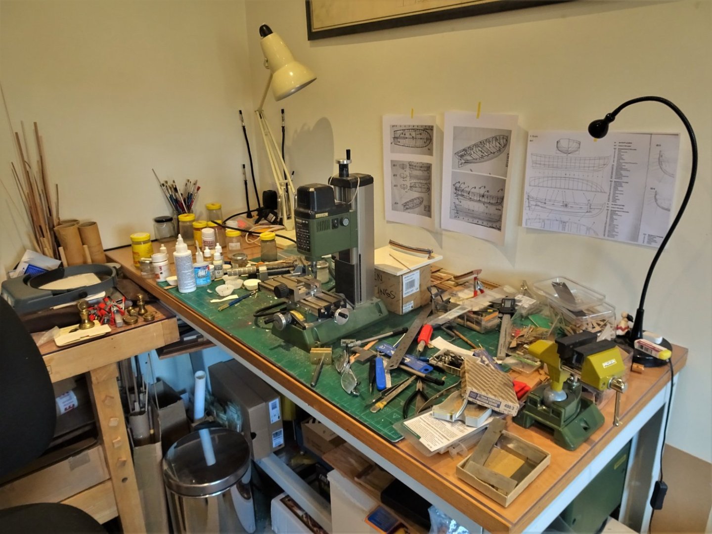
Post One Hundred and fifty-four Fitting out the Pinnace – Part two Decking and gratings These take the form of brass etch which I last used on my previous Yawl build. Chemical blackening after scrub with fine wire wool, and an acetone dip, helps provide a key for the paint. 7896 Base coat of Burnt umber, followed by Ochre Brown, followed by lighter shades of ochre. I am using Vallejo paints throughout. 7898 Insitu, I thought the colour tone looked too strong against the Pearwood. 7900 I then added a further coats using White/grey tinted with a spot of Ochre brown. 7902 I prefer the paler tone, but not quite there yet. I next fitted the wales using the last two planking strips of the provided set. 7908 These were painted Black/grey as on the main model. 7910 Sorry about my work bench, it invariably gets covered with stuff until I reach the point where I can’t find the last thing I put down. At that point I have to have a gtu, I’m close to that point now. This is a fairly plain version of a Pinnace but I wanted it to reflect the main model in terms of its colouring and decoration. 7915 I added a decorative frieze along the Topsides above the wale, but intend to leave as much of a varnish finish as I can. 7913 Fitting the Sternsheets which come as a combined unit took a little careful fettlin’ to get them to sit down at the correct level within the hull. 7917 A final application of sand yellow weathering powder brings the colour tone of the decking up a little. 7920 Using scale figures helps to ensure that the Sternsheets are at the right level. 7921 I am pleased to see they are a perfect fit for the Sternsheets. Work will now continue to add detail to the sternsheets, and attend to areas requiring a little more cleaning up as revealed by the macros. B.E. 15/08/2022


- 857 replies
-
- 18
-
-
- Sphinx
- Vanguard Models
- (and 1 more)
.JPG.7296ffb049e2f0539de751e6daee16a0.JPG)
.JPG.e54dbbf76c130460b42d88093e0ab985.JPG)


.JPG.67823d626fb67a84a3645e5f3b588f68.JPG)
.JPG.6d75458cd0cd4d0275f69b340b5fd336.JPG)
.JPG.1061d1d4bcd957a5ef125f776168f4c1.JPG)


.JPG.862d4346879c070c85d268f2840972cb.JPG)
.JPG.edcafc7730866ff66e481136741601ad.JPG)
.JPG.d063cb4553e149c899befa22ff605c97.JPG)
.JPG.4c52844741d794b17dd6f2c04408c3c3.JPG)
.JPG.51d1ba8ad77ed25255a1670347733233.JPG)


.JPG.ac34268eed008043cfffdd880276cc48.JPG)
.JPG.e1ea585ff44302b146f9ecf24d49b98e.JPG)
.JPG.c08435bc54939d01f107729e330d2608.JPG)
.JPG.ed5034288869bf150827095f5e8d6361.JPG)


.JPG.fcc9cb55c1ab0a443d728b458ecd1db9.JPG)
.JPG.0d22481b197b6eb2b8dae7d4a8f9e6df.JPG)
.JPG.7306a151cc3e76dd7ed0833551958641.JPG)
.JPG.fc0dc4854ec21948cef9fadccd10e617.JPG)

.JPG.71018ad9a31e62e94570019f34140ad5.JPG)


.JPG.7b8ee0590de8d4456f9c3e9937691165.JPG)
.JPG.50e898d03e67fd60cc711df9ec681b2b.JPG)

.JPG.da631e6b1d8e6b92a314b9875e9fe4f2.JPG)
.JPG.c03b59eedc6a8640b22988494f915280.JPG)

.JPG.50188d29bdd101a3a9ade0ba0a64033c.JPG)
.JPG.6512e16cf3d9e0b6f26944f9f129b017.JPG)
.JPG.df9a7ad421e1ec22e589c7909dee52a6.JPG)


.JPG.8bac6b6ccd93eef69260f3463cb3e90c.JPG)