
HOLIDAY DONATION DRIVE - SUPPORT MSW - DO YOUR PART TO KEEP THIS GREAT FORUM GOING! (89 donations so far out of 49,000 members - C'mon guys!)
×
.JPG.ca33079f5815b861e67b9c2cccd37982.JPG)

Blue Ensign
-
Posts
4,566 -
Joined
-
Last visited
Content Type
Profiles
Forums
Gallery
Events
Everything posted by Blue Ensign
-
 Thank you Steve for your kind words, I'm glad you enjoyed the log. I'm sure you will enjoy the kit it's a great little build. I have a visit to Anstruther on my bucket list, maybe next year, a bit of a haul at around 350 miles, and I would want to make sure the Reaper was doing trips. Regards, B.E.
- 195 replies
-
- 2
-

-
- lady eleanor
- vanguard models
- (and 1 more)
-
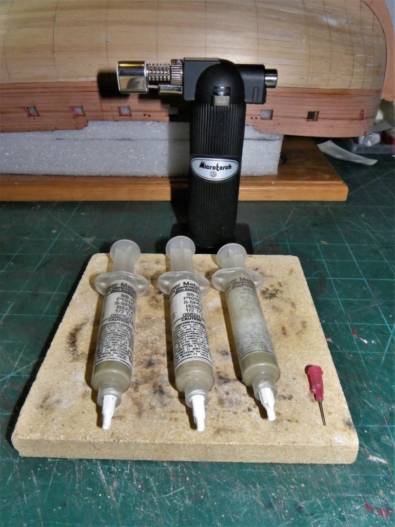
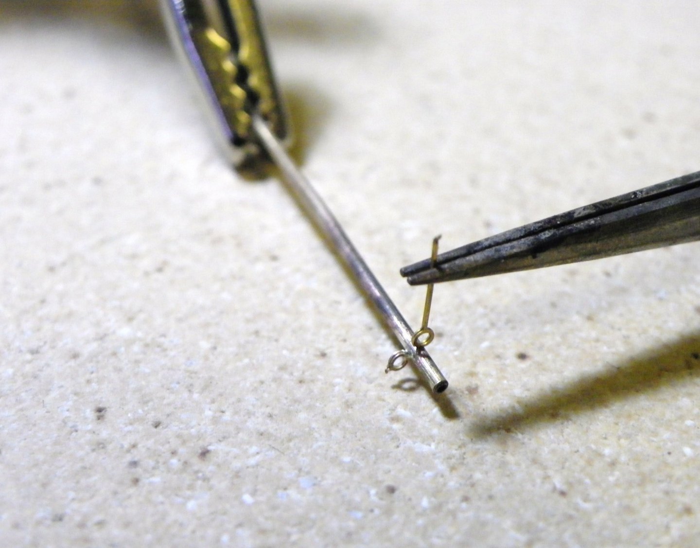
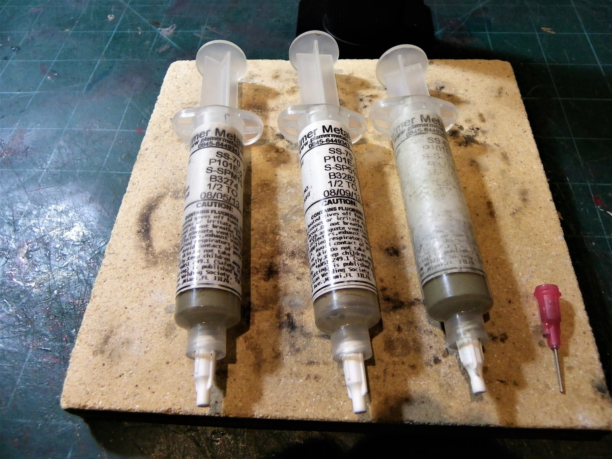
Hi bug and Bob, Silver soldering is well worth adding to your skill set, and at a basic level is quite easy to do. This is my set up, a burner, a pad to work on and tubes of ready to use silver solder. It is important to have different melt points if more than two pieces are to be soldered together. The tubes above have melt points of 671, 690, and 740 degrees. This photo shows two fine brass eyelets soldered to a brass tube to make a stanchion. The parts must be clean, and devices used to hold the parts together. In the case above one ring is soldered, and then the second with a lower melt point. A small amount of solder is put on the tube, the eyelet is held in position, the torch flame applied until the silver flashes, and job done. With fine material like this it takes a second. Hold it too close or for too long and the brass pieces melt. Getting inventive with ways to hold the pieces for soldering is a big part of the process, apart form a third hand tool and self closing tweezers, I use blu tack to keep pieces in position where required. One advantage with silver soldering is that once cleaned up it takes blackening very well. Hope this helps. B.E.

- 419 replies
-
- 8
-
-

-
- Victory Models
- Pegasus
- (and 2 more)
-
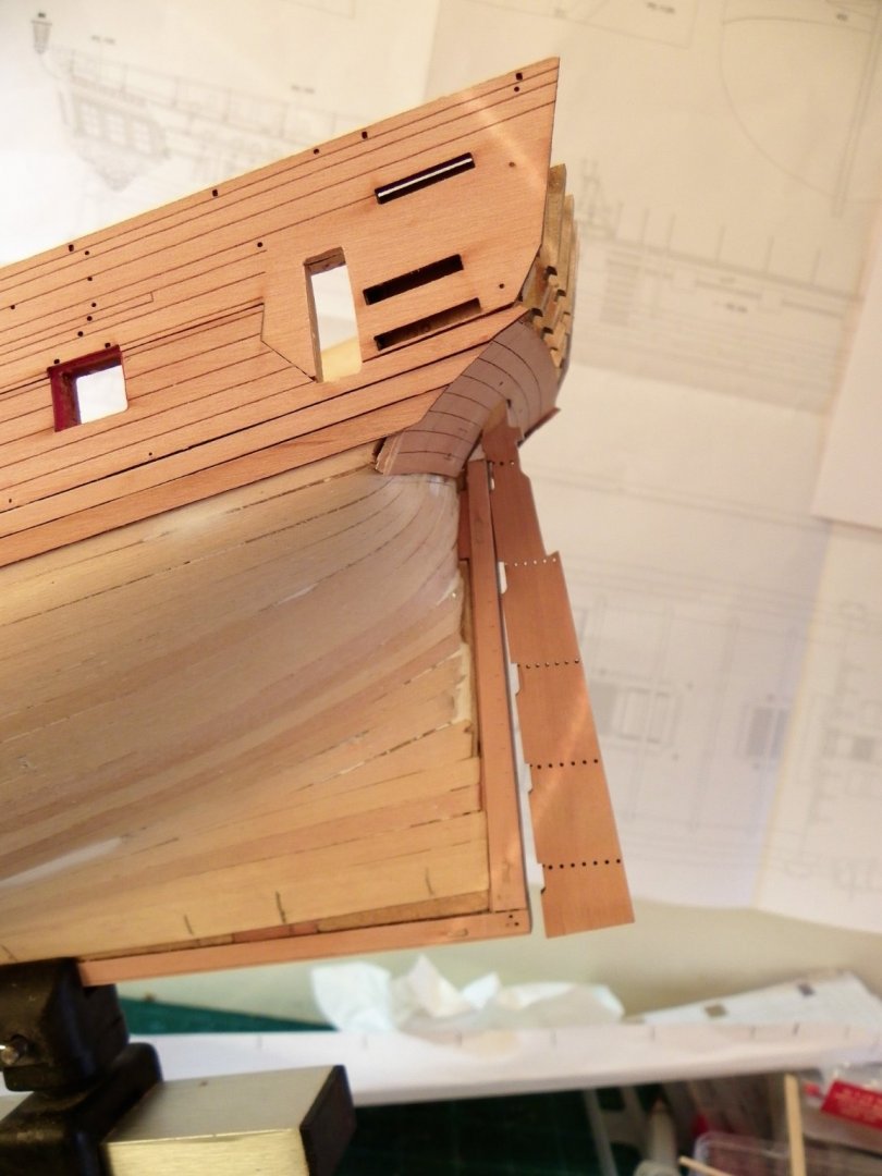
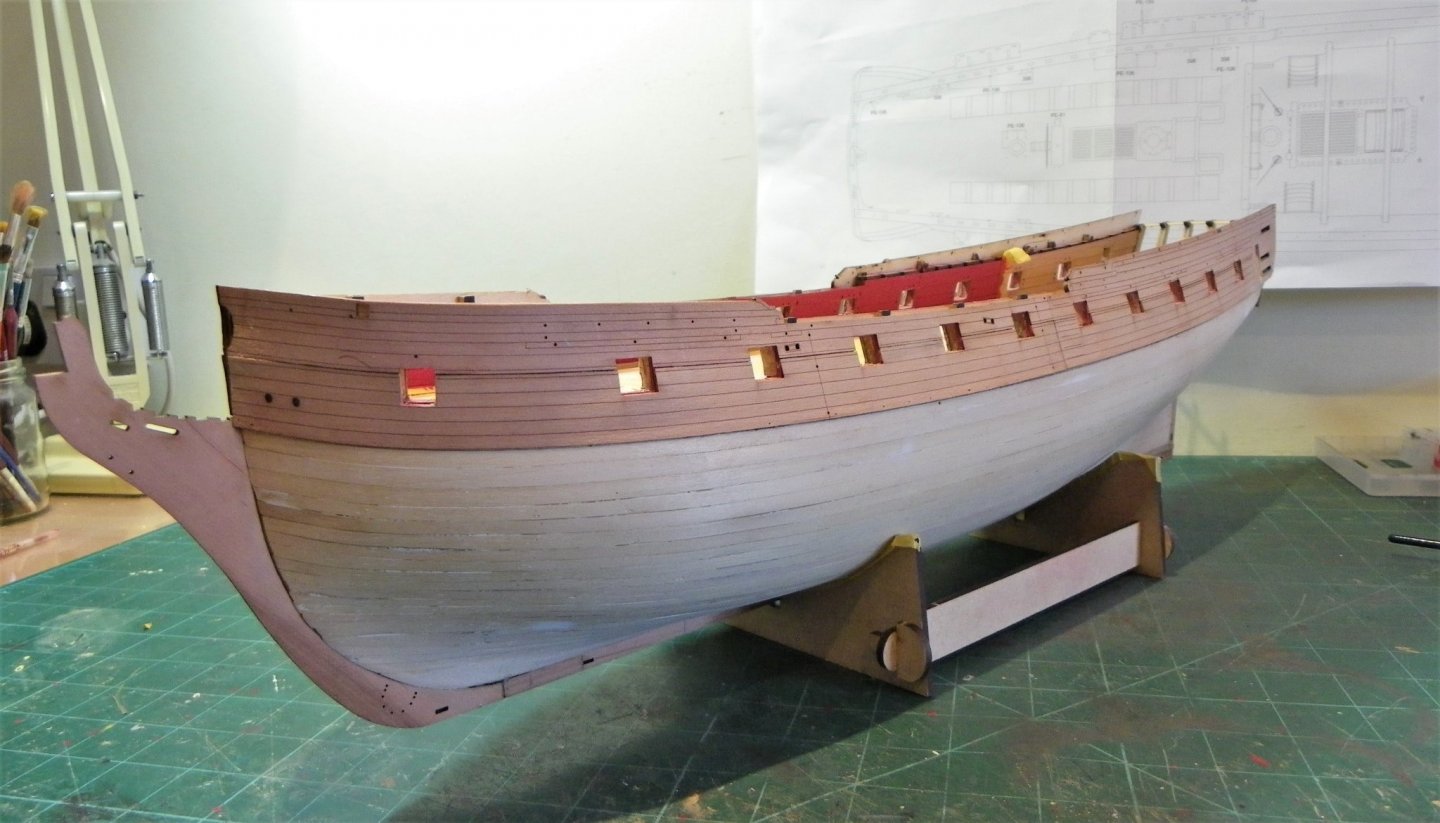
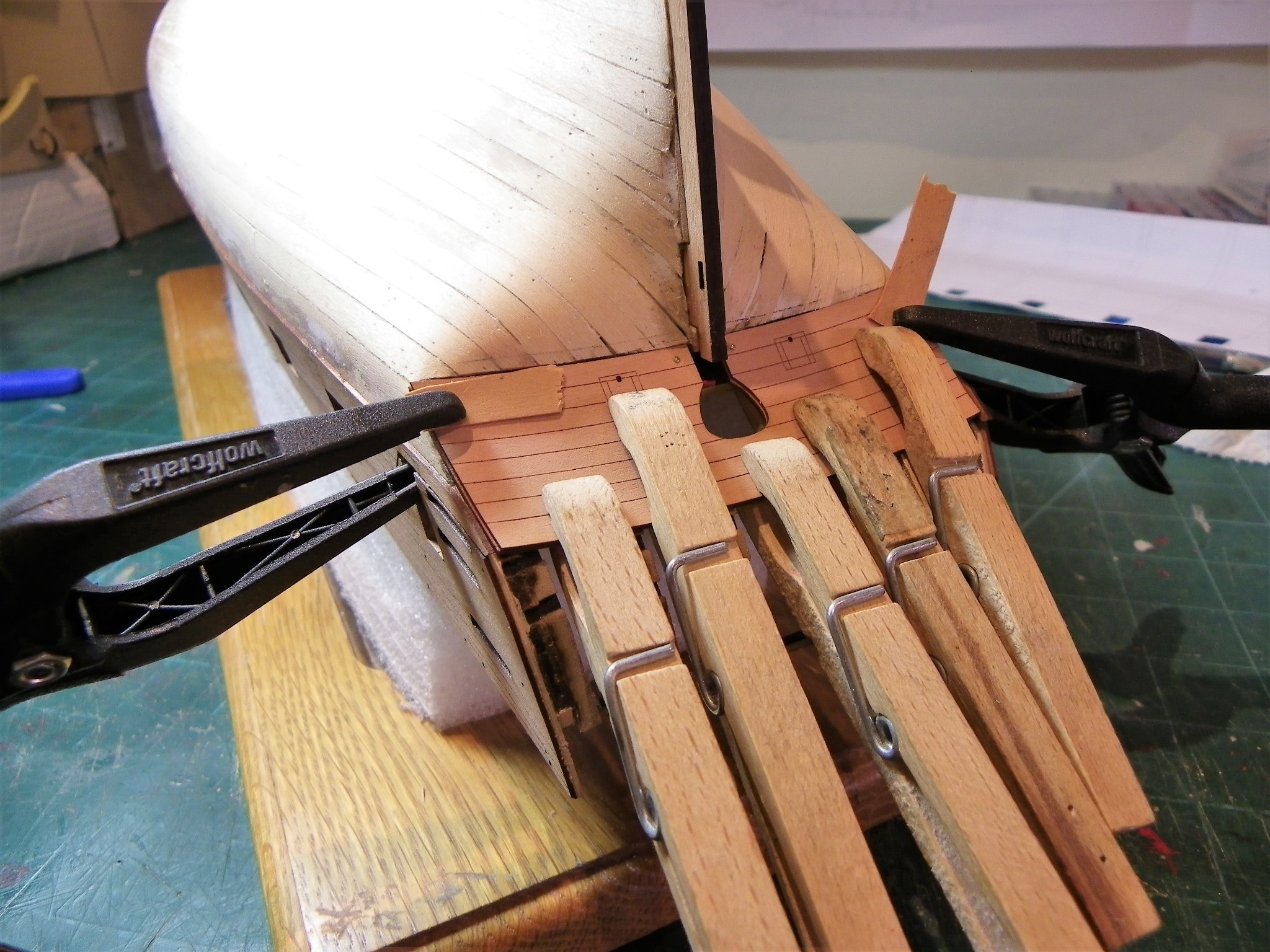
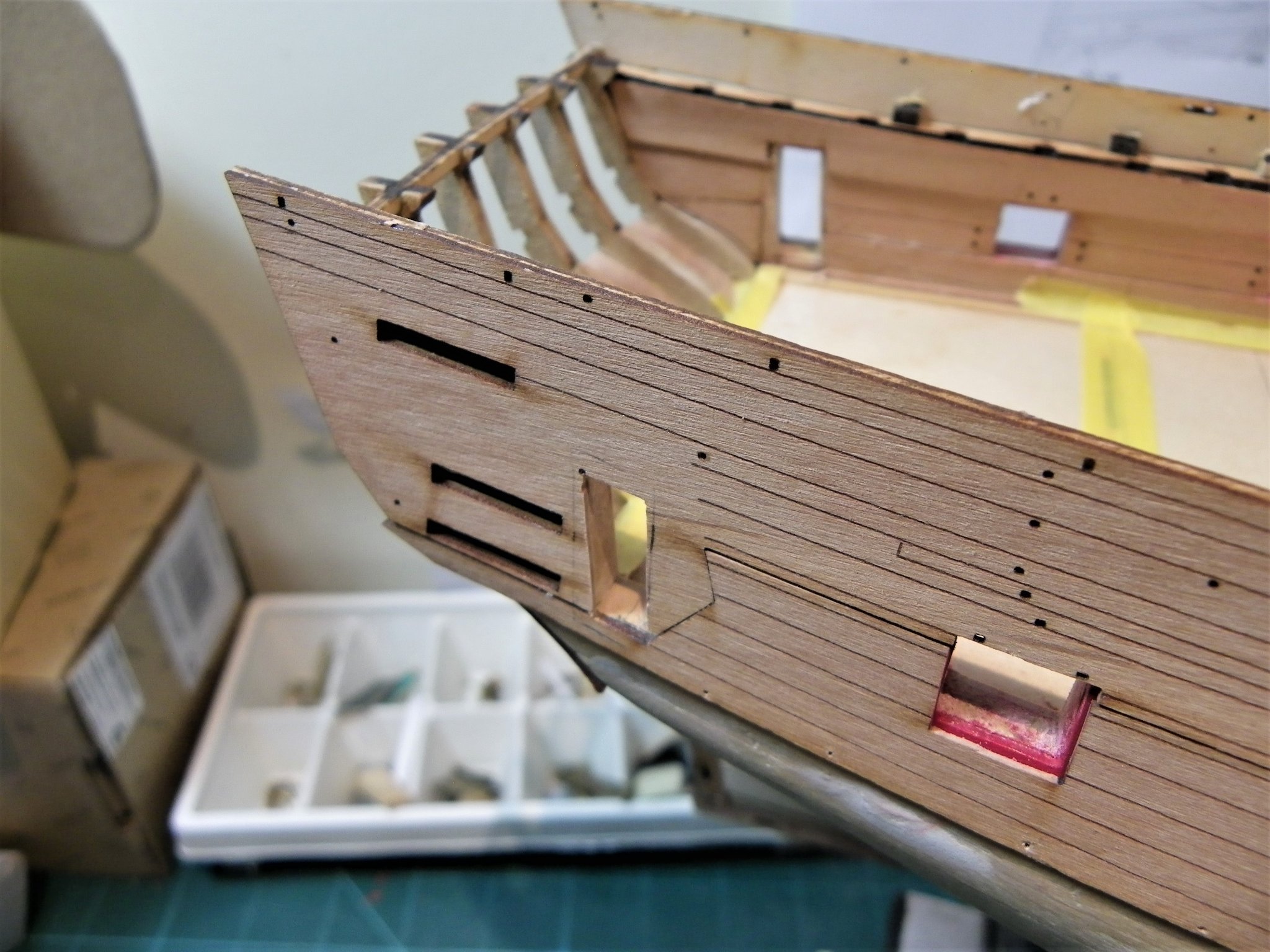
Post Thirty-three Completing Keel, Knee of the Head, and sternposts As is common with Vanguard kits, cover pieces of Pearwood or outer patterns as they are described are used to provide a pristine finish to these parts which are of themselves Pearwood. This is a great improvement on having mdf or ply versions which are difficult to match to the finishing timbers. I well remember the time I spent in getting the mdf Prow on Pegasus to match the Boxwood planking. 1059 The ‘Prow’ piece is also nicely engraved with the various sections that would otherwise make up the knee of the Head. Before I fitted these pieces I fined down the first layer planking a little in places to provide a slightly better rabbet for the second planking running into the bow. It really helps to have a rabbet to get a nice clean and tight look to the bow timbers, and also helps with the fitting. 1041 The most prominent feature is the Prow piece and it fitted spot on, I was careful not to get any glue stains on the surface. 1045 Following on from the Prow the keel and sternpost pieces slot into place without issue. 1042 Finally there is the lower counter upper pattern to fit followed by two further strakes of pre spiled planking. 1058 I used ca gel for these two planks, but I did keep a pot of acetone on hand in case of marks. I really dislike ca and will probably only use it to secure the first few inches of the planks at the bow. 1050 One slightly worrying thing, out of curiosity I tried fitting the rudder in place. It looks like it won’t fit without enlarging the rudder port in the lower counter. Probably down to something I’ve done, but it’s not a big issue to adjust. With these fitted, it’s onto the wonderful world of hull planking and all it entails. B.E. 04/11/21


- 857 replies
-
- 22
-
-
- Sphinx
- Vanguard Models
- (and 1 more)
-
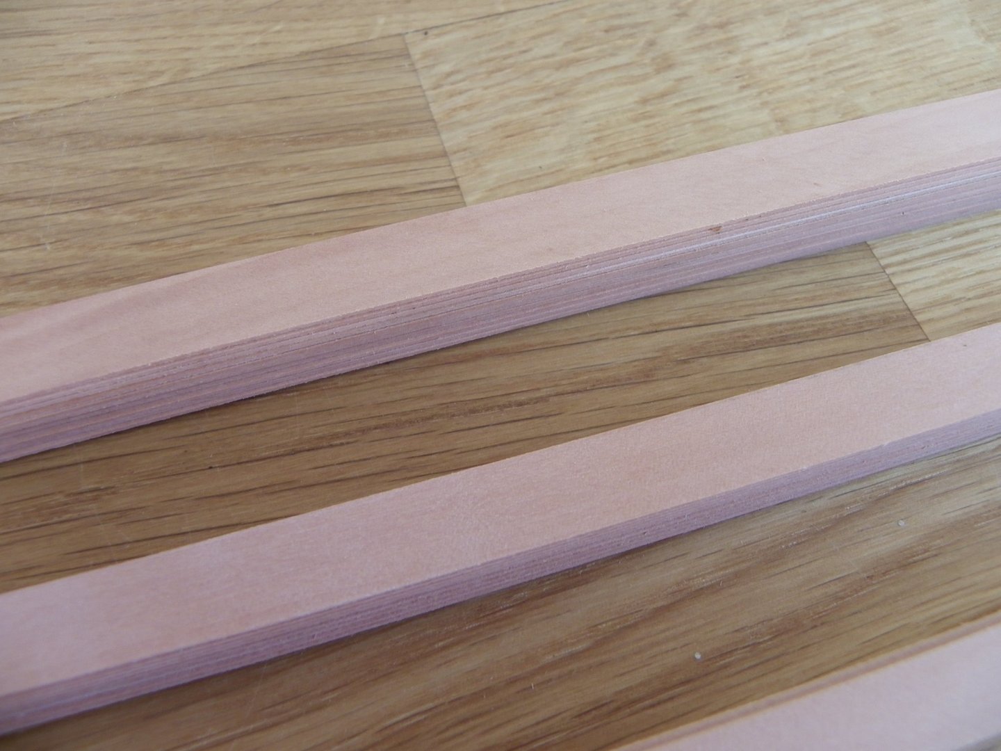
This is an extract from my current build log about my first order from HobbyMill EU In preparation for hull planking I ordered a full range of Pearwood strip. 1023(2) Strip Pale Pearwood timber, the longer paler strips are the kit supplied Pearwood for comparison. Each size of timber comes in packs of 10, sufficient for most spiling requirements, and the range of plank widths will allow me more flexibility. The whole process of ordering was a pleasure, Vahur is very helpful, kept me fully informed by email, and provided full tracking details. I received the timber 15 days after order. The timber was well packed and presented in separate plastic sleeves for each size. It is of excellent quality and pale in colour as ordered. I did a random check of dimensions and the tolerences seemed to be in the range of +0.1/-0.1 in widths. Extra strips were included in each packet to allow for any discrepancies. In the 0.8mm x 1mm strips an extra 6 pieces were included with the 10 ordered. 1030(2) The lower strips are the kit provided strip, and the upper ones the Hobbymill. The kit strips are paler in colour, but the hobbymill versions a closer match to the planking patterns. 1027(2) The colour tone across the range is even. The longer paler strips in the photo are the kit provided strip. 1028 These are the 10mm and 0.9mm strips. In addition to the strip wood I ordered some square/rectangular stock. 1035(2) This will be used for constructional elements that may arise. Finally, Vahur included some samples of other available timbers, Yellow cedar, Hornbeam, Dark Pearwood, Boxwood, and Holly. All looking to be of excellent quality and cleanly cut. I am happy that we have at last got a European supplier of quality timbers, and on the strength of my first order I am happy to recommend. B.E.
.thumb.JPG.480ea0bff5086976b5c6e276627253a6.JPG)
.thumb.JPG.487b8e7d4fd622ac093d9508e9de869c.JPG)
.thumb.JPG.bfab0a31a6308a81b684bc33bbbfad61.JPG)
.thumb.JPG.a7bc582cae86fef1901a2f5b108101ca.JPG)
- 75 replies
-
- 12
-
-
I agree with you Chris, I don't like the Walnut look on models; I replaced all of the planking timber on my Pegasus build with Boxwood, and I toyed with doing that on Sphinx, but I think the Pear is nice enough. The deck will be Boxwood tho'. B.E.
- 857 replies
-
- 5
-
-
- Sphinx
- Vanguard Models
- (and 1 more)
-
Extra Timber supplies. In preparation for hull planking I ordered a full range of Pearwood strip from Hobbymill EU, based in Estonia, and a recent sponsor of MSW. 1023(2) Each size of timber comes in packs of 10, sufficient for most spiling requirements, and the range of plank widths will allow me more flexibility. The whole process of ordering was a pleasure, Vahur is very helpful, kept me fully informed by email, and provided full tracking details. I received the timber 15 days after order. The timber was well packed and presented in separate plastic sleeves for each size. It is of excellent quality and pale in colour as ordered. I did a random check of dimensions and the tolerences seemed to be in the range of +0.1/-0.1 in widths. Extra stips were included in each packet to allow for any discrepancies. In the 0.8mm x 1mm strips an extra 6 pieces were included with the 10 ordered. 1030(2) The lower strips are the kit provided strip, and the upper ones the Hobbymill. The kit strips are paler in colour, but the hobbymill versions a closer match to the planking patterns. 1027(2) The colour tone across the range is even. The longer paler strips in the photo are the kit provided strip. 1028 These are the 10mm and 0.9mm strips. In addition to the strip wood I ordered some square/rectangular stock. 1035(2) This will be used for constructional elements that may arise. Finally, Vahur included some samples of other available timbers, Yellow cedar, Hornbeam, Dark Pearwood, Boxwood, and Holly. All looking to be of excellent quality and cleanly cut. I am happy that we have at last got a European supplier of quality timbers, and on the strength of my first order I am happy to recommend. B.E.
.thumb.JPG.bfd19e3256e7cbce626471faa088344f.JPG)
.thumb.JPG.05bef70867f84ccf483aa2c9eefa243c.JPG)

.thumb.JPG.75868fffa4ae0dd93ecbf52bfb2dd443.JPG)
.thumb.JPG.8acb161f9ea9b06f03e7be5f20648b2e.JPG)
- 857 replies
-
- 17
-
-
- Sphinx
- Vanguard Models
- (and 1 more)
-
Well done Jacek, what a difference the Chuck approach has. 👍 B.E.
-
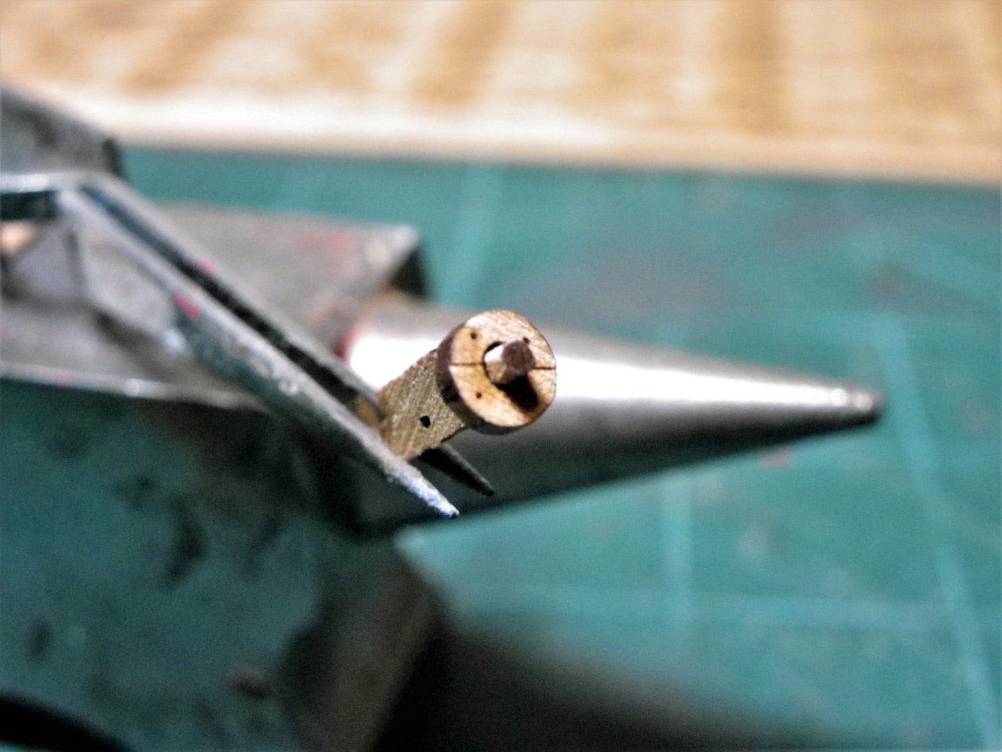
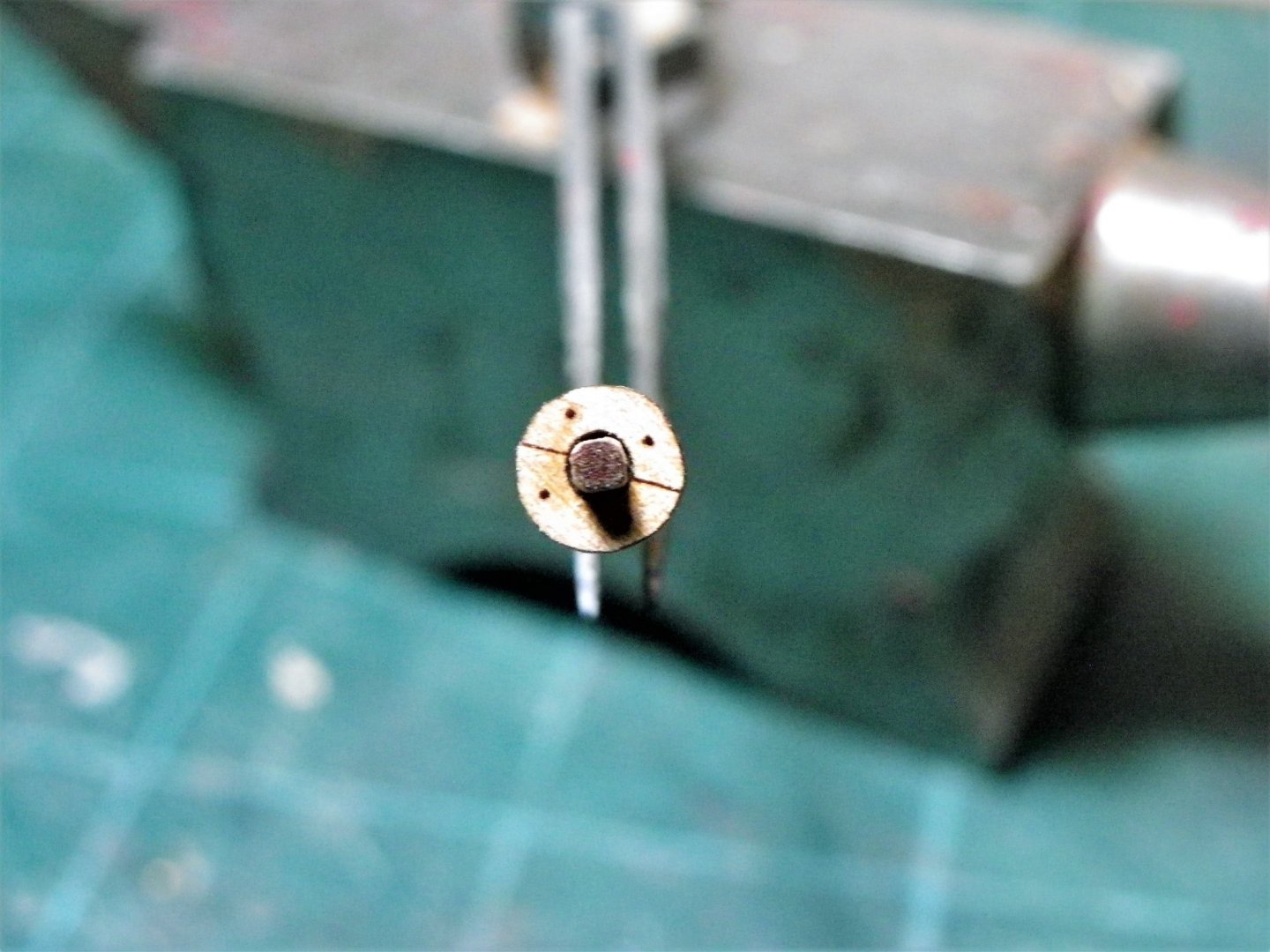
I don’t think I could trust myself with any sort of power option to round what are quite delicate and small scale pieces. In relation specifically to Sphinx only the slightest pass of a sanding stick is required on the square edges of the axle to allow the truck to fit. The area involved is only 2mm x1mm. 1020 It is difficult to get a perfect fit as a square peg is being inserted into a round hole. 1021 To counter this the axles would need to be a fraction larger to allow rounding for a full fit. The above macro shots show the problem, but at scale size it is a minor issue, just use the lightest touch to get them to fit. B.E.
- 857 replies
-
- 13
-
-
- Sphinx
- Vanguard Models
- (and 1 more)
-
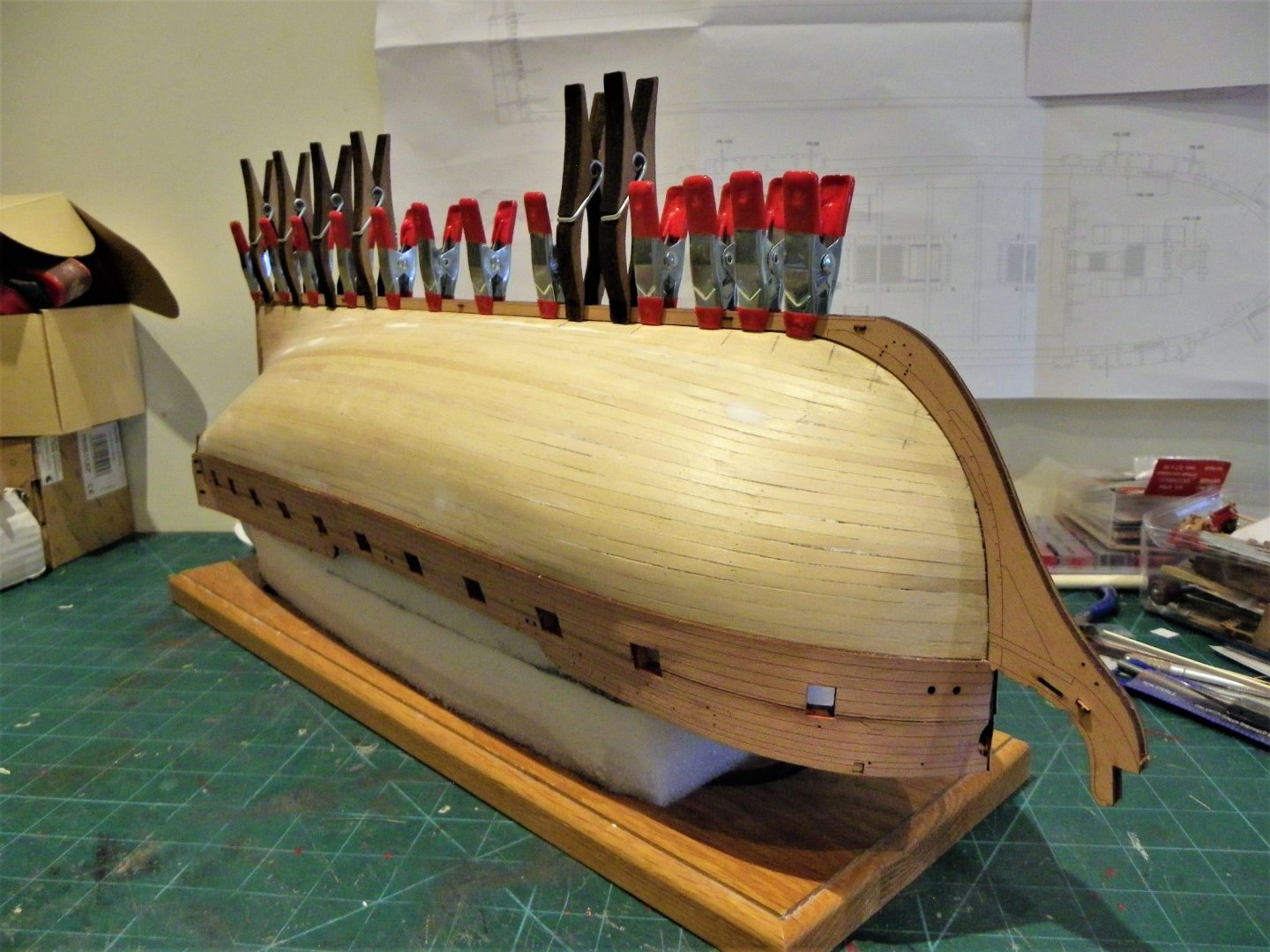
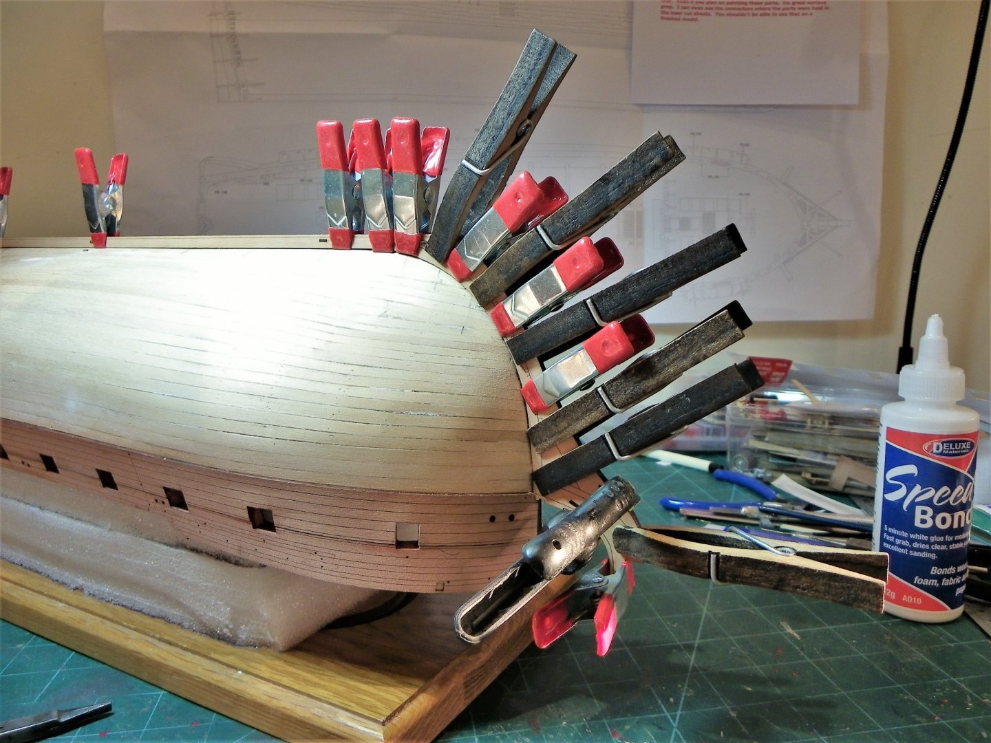
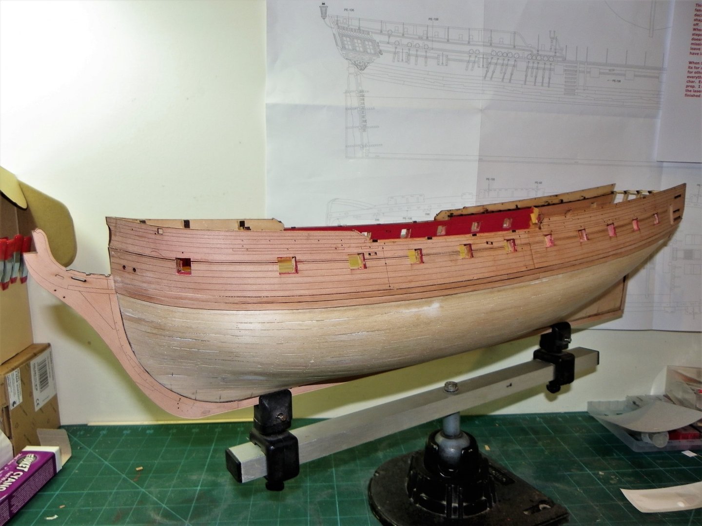
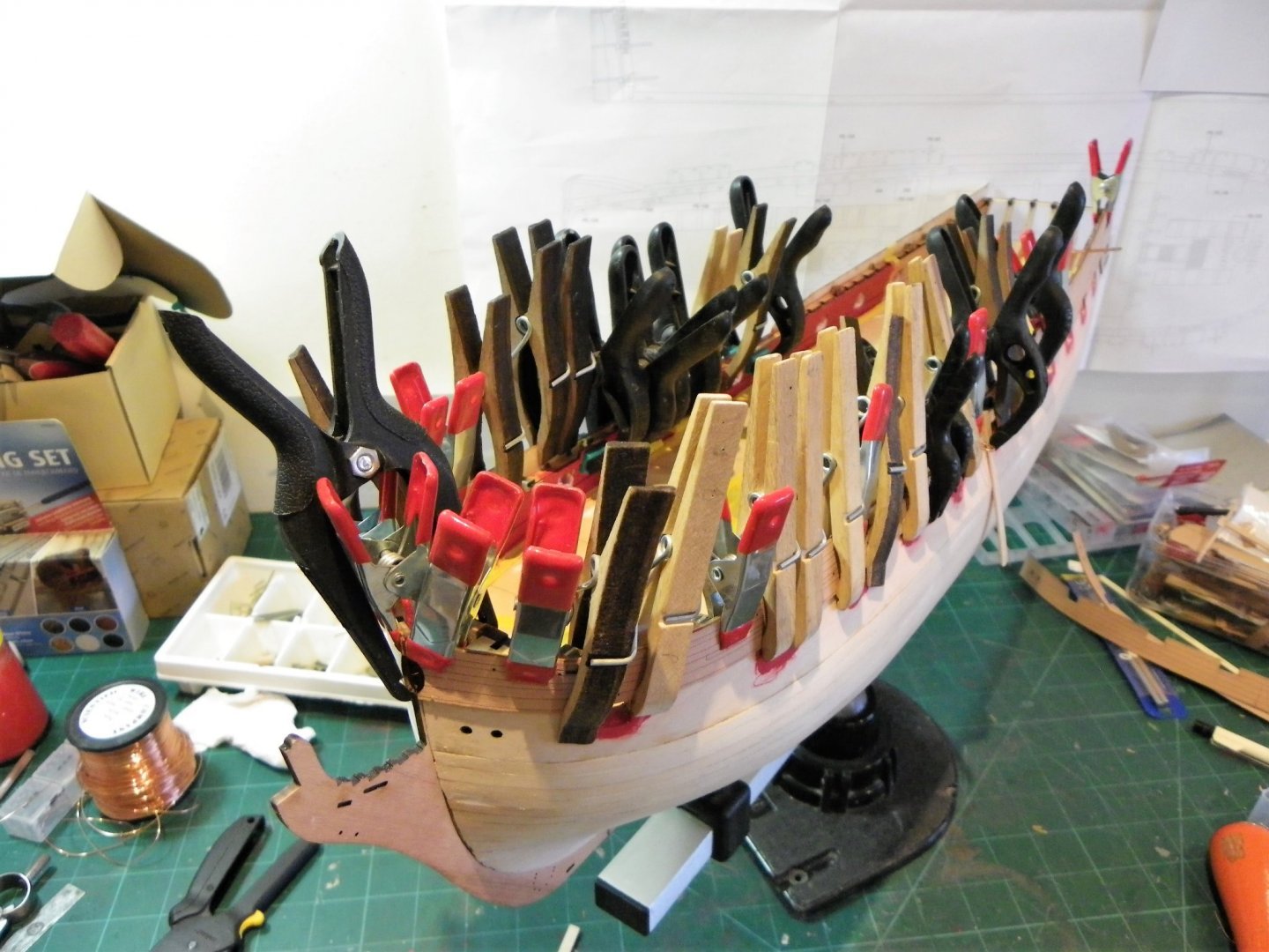
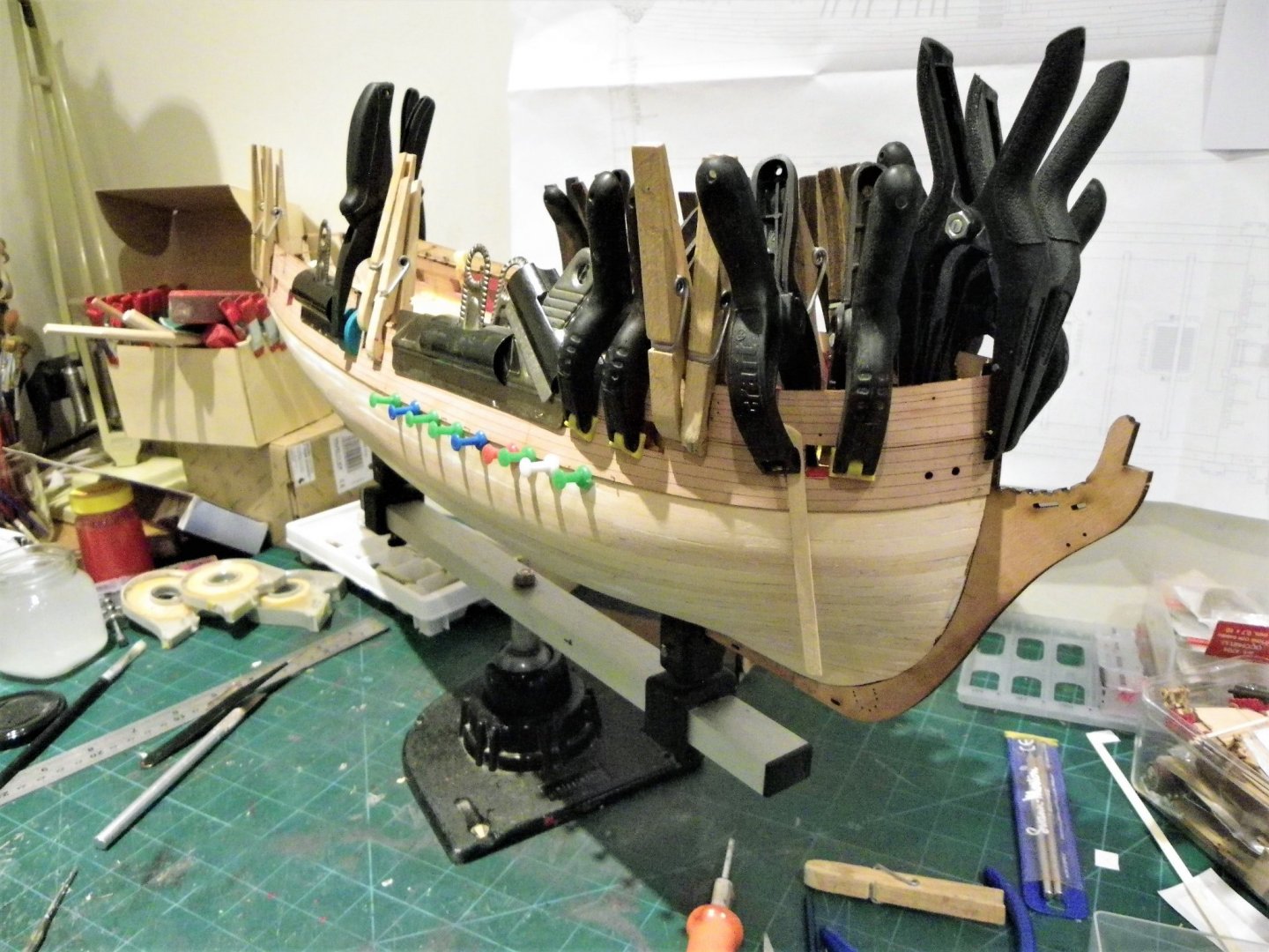
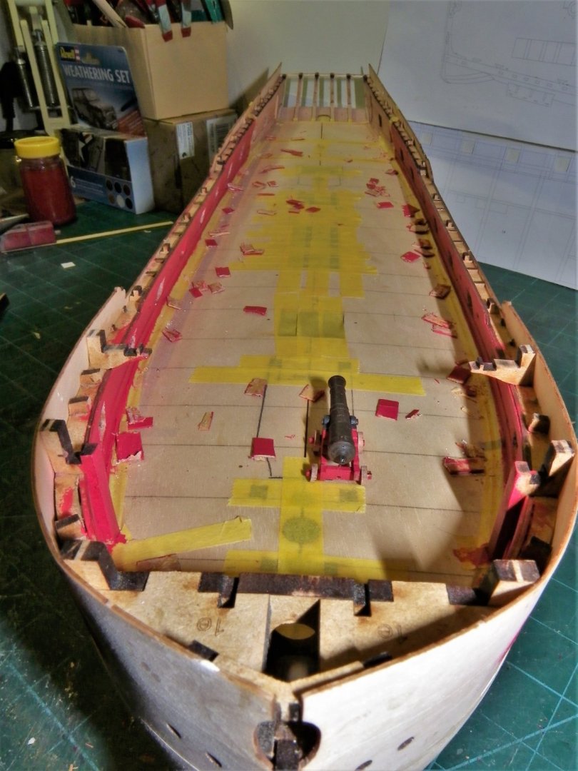
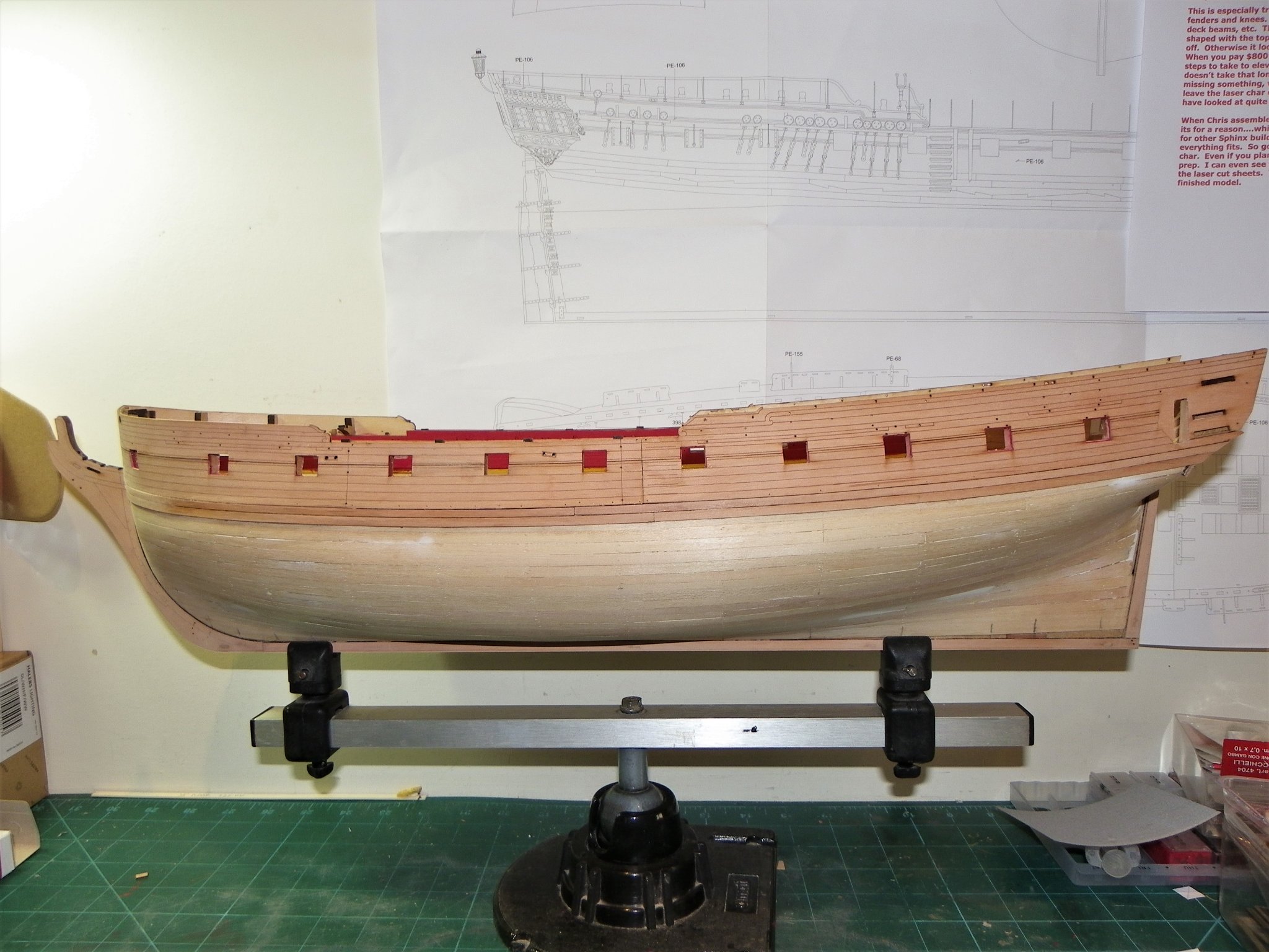
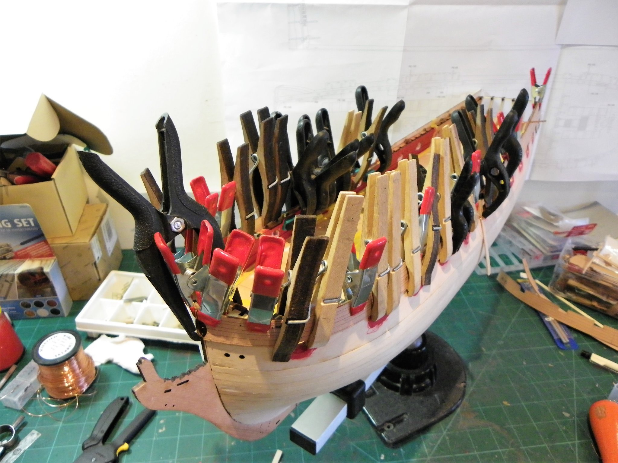
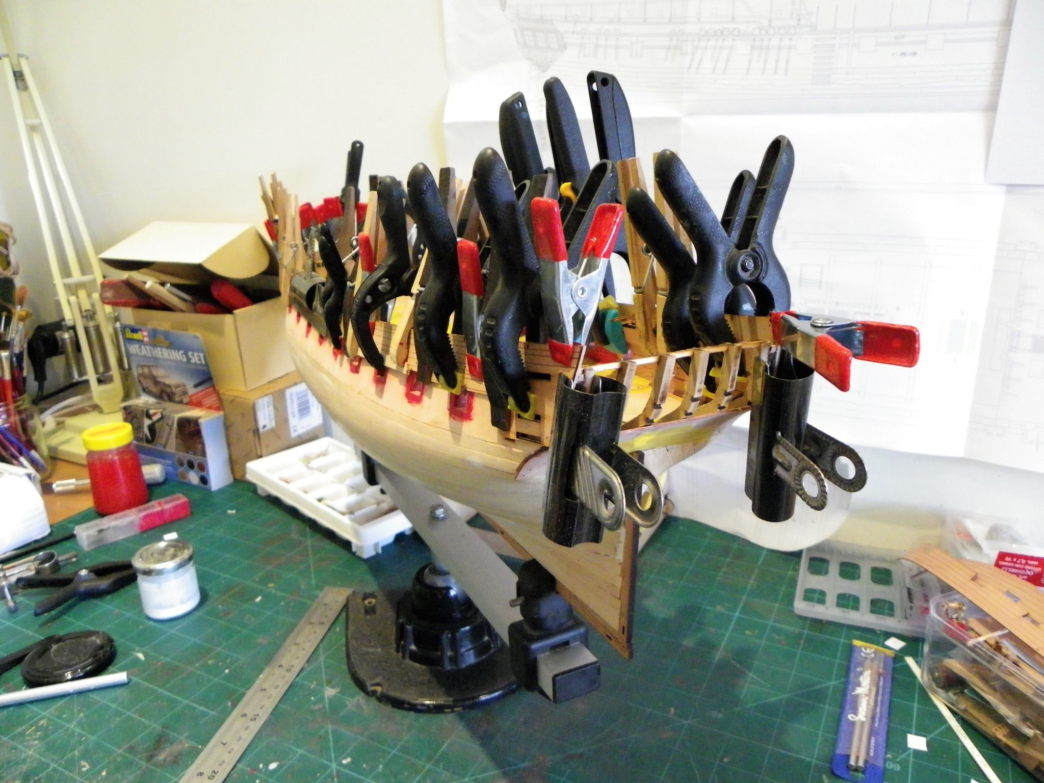
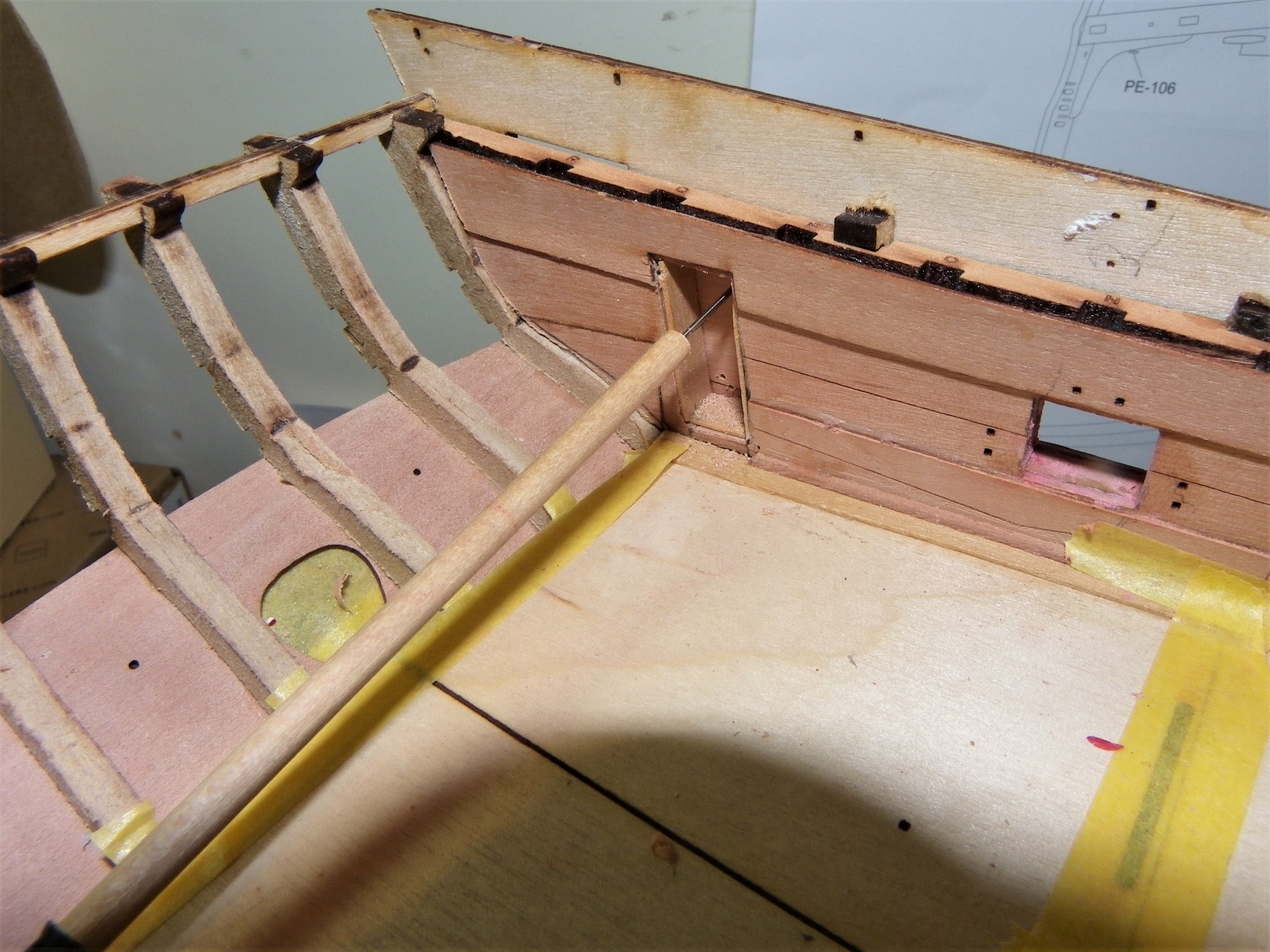
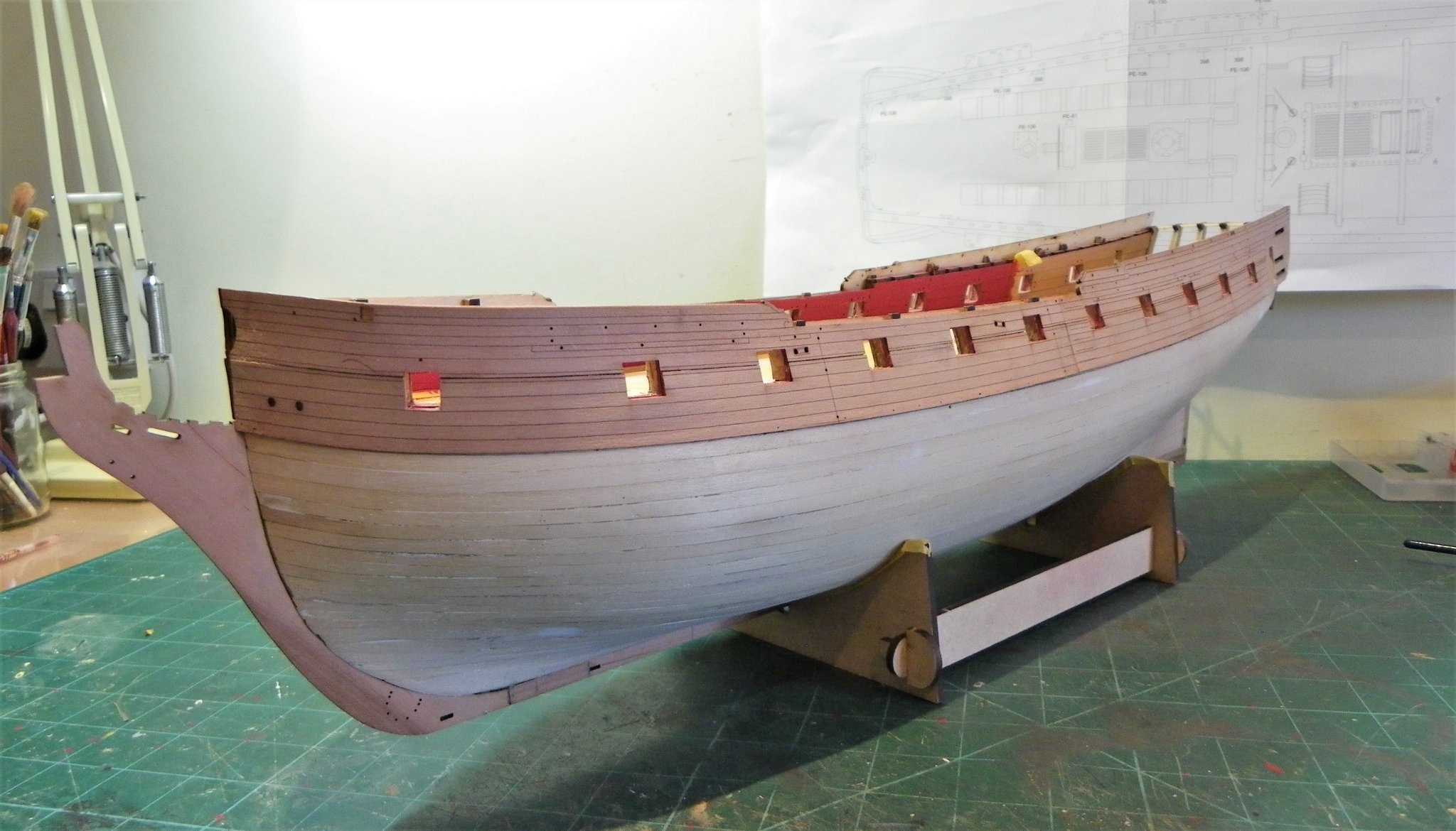
Post Thirty-two Planking by numbers, the Pearwood journey begins. Soaked and clamped the patterns are shaped to the hull form. 0985(2) While I wait for the planking patterns to dry out I make up a range of sanding sticks using P240 grade paper. 0983(2) Some of them are size specific ie for gunports, others narrower to get into smaller places. Small ones are also used for char removal on small pieces. Once the initial bite has gone from the papers I use the older ones for finer sanding. Time to fit those pretty planking strip patterns. I begin the fixing by clamping the Rear upper pattern in its correct position, and then trial fitting the Fore pattern to ensure that everything lines up before committing to glue. 0996 I keep a jar of clean water handy to wash off any glue marks that may get on the Pearwood surface from handling. 0997 I fit the upper aft patterns next, and repeat the process for the lower patterns. I think I exhausted my entire eclectic stock of clamps on this. 0999 The lower patterns I found more tricky to fit as they had a tendency to curl on the bottom edge, requiring pinning. There was also a slight mismatch on some of the port edges even tho’ the sections seemed to meet up in the critical areas. I had originally contemplated planking the lower portion of the pattern area, but once again find myself seduced by Chris’s design. 1012(2) The only modifications I made was to remove the closed lids of the Bridle ports on the fore sections, and cut the doorway for the Quarter gallery on the aft sections. 1011 The doorways were cut post fitting from the opposite side of the hull by marking the outline with micro drill holes. 1003 I use a drill ca’d into a length of dowel for reach.* I otherwise followed the arrangement set out in the manual. * This is a useful device for drilling holes in bulwarks where space and angle are an issue. With Sphinx, Chris has thoughtfully pre drilled the holes for the gun tackle hardware, so no drilling is necessary. 1015 With the patterns in place I am better able to see what is required regarding port linings. 1013 1018(2) It is a bit of a pain, but leaving the core of mdf uncovered is not something I would want to do. Linings or stops are a pretty basic addition to a build of this scale, and consist of a cill and two sides, there is no top lining. Again I will use 0.6mm Boxwood strip,(true scale) anything thicker would reduce the port sizes too much. I will defer this job and fit it in with other work over the next couple of stages. Following on from the patterns there are two further strakes of pre spiled planking, but before these are fitted I need to look at the outer patterns for the stem, keel, and sternpost, and the outer lower counter pattern. B.E. 02/11/21
.thumb.JPG.24e3c66f176f9e965ef799b37f0e8665.JPG)
.thumb.JPG.416ed47ce60b9695f0d05469e00a1ef8.JPG)


.thumb.JPG.9c127e3ca069efe25ff009af55a9e506.JPG)

.thumb.JPG.b526010a01aabc078235bb27781468b6.JPG)
- 857 replies
-
- 20
-
-
- Sphinx
- Vanguard Models
- (and 1 more)
-
Note for the record - I don’t do rant. Cheers, B.E.
-
That bow shot looks good Jacek, well done. B.E.
-
Tempter - but I'll hold out - at least for the present, I've rather got my hands full.😀 B.E.
-
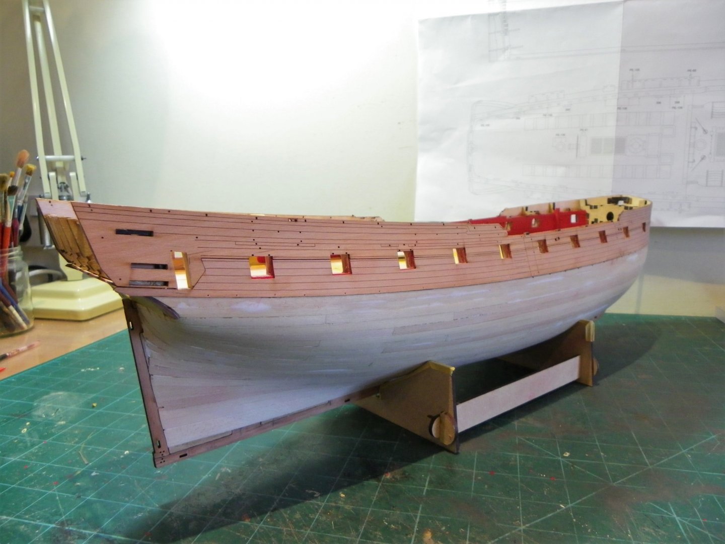
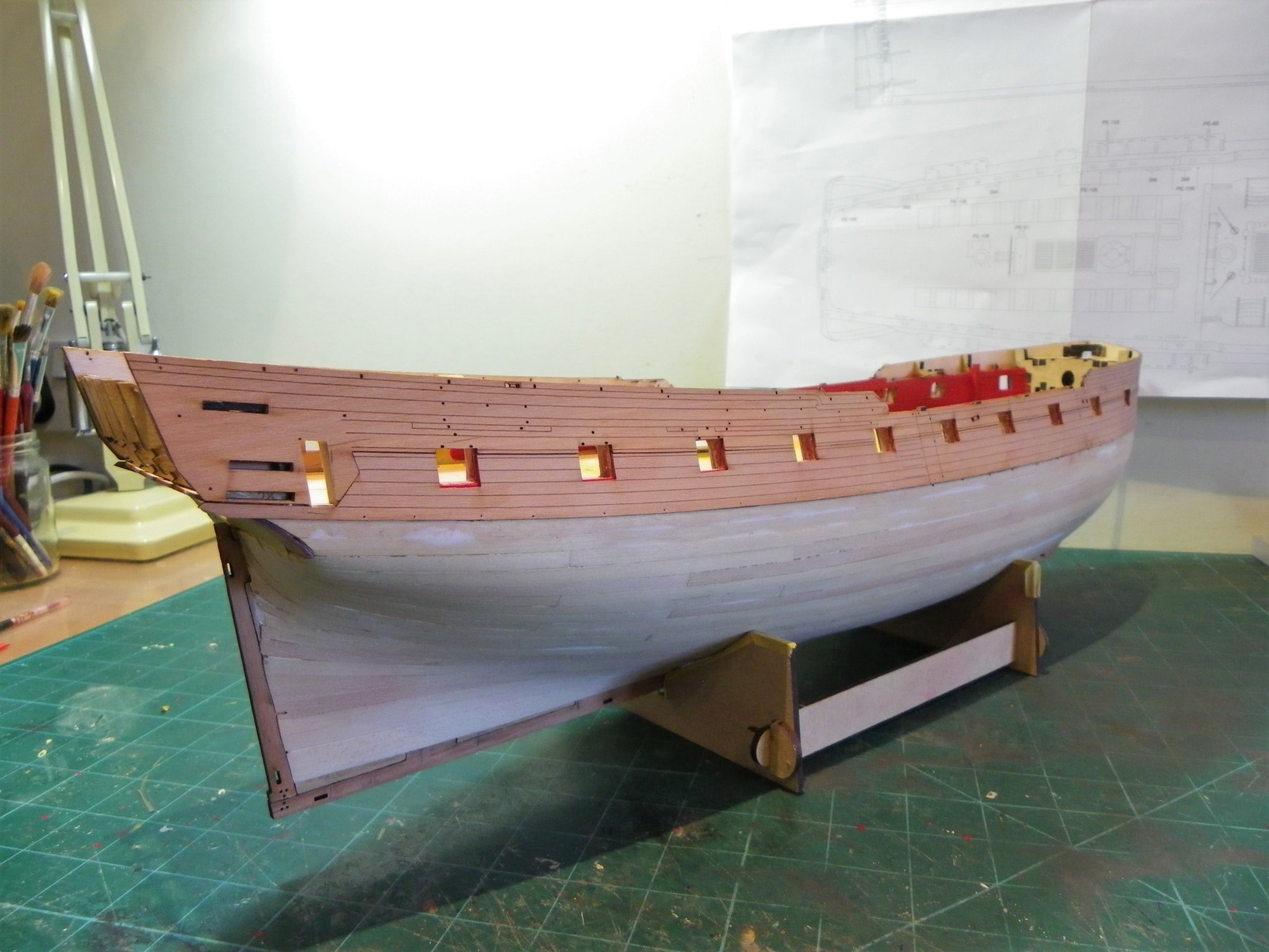
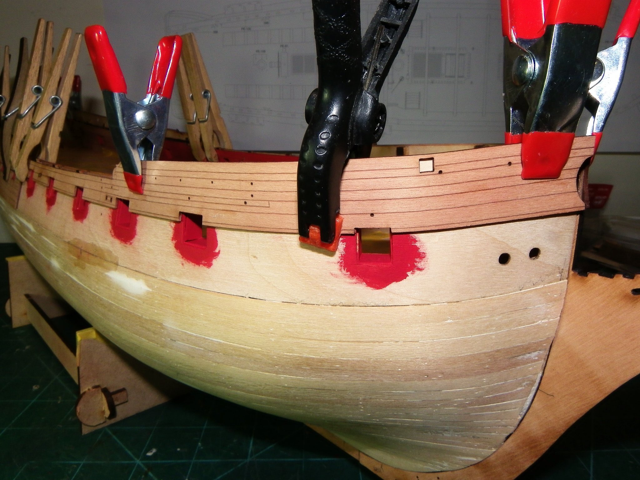
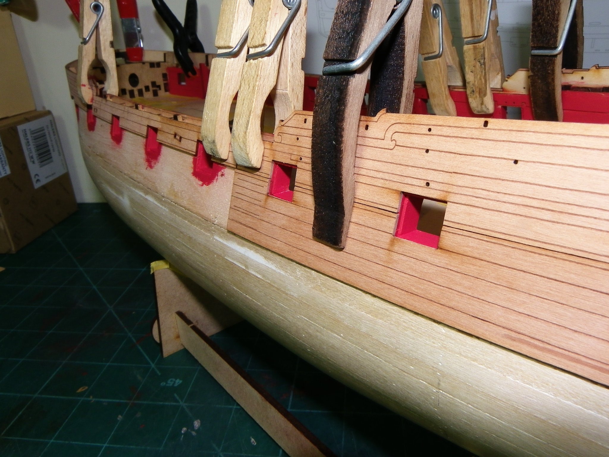
Post Thirty-one A backward step Having fitted the port linings I added a further coat of paint prior to fitting the pre formed planking strip patterns which effectively take the planking down to the bottom of the Gunport pattern. These look good and do save a lot of fine cutting around gunports. However, trial fitting of the planking patterns raised doubts in my mind about the linings. 0964 I originally fitted port linings in advance of fitting the outer planking patterns in an effort to avoid getting paint on the pattern edges. They would in normal practice be fitted once the outer planking had been completed. 0961 I have at this point soaked the bow patterns and clamped overnight. 0965(2) With the patterns applied I’m unhappy with the look. I think they should really meet the inner line of the outer patterns rather than of the gunport pattern, so off they must come. 0974(2) The sad detritus litters the deck. 0969 That’s two days of my life I’ll not get back, a penalty of kit fiddling. Hey ho. B.E. 29/10/21


.thumb.JPG.1db219c784caf3d5e0a367839a06fa4c.JPG)
.thumb.JPG.60fb414d87e7f1e33f081d29c56ba15d.JPG)
- 857 replies
-
- 14
-
-

-
- Sphinx
- Vanguard Models
- (and 1 more)
-
I would certainly appreciate knowing your technique for char removal Chuck, post it on my log if you wish, also for the benefit of other Sphinx builders. B.E.
-
I sense Chuck's frustration at seeing what should be a wonderful model not being presented at its best for want of simple actions. I have copied his words at the head of each section of my log record as a reminder not to be tempted to cut corners, and leave undone that what should be done. B.E.
-
Toothpicks are an obvious choice, but they are quite soft and difficult to get a clean cut. With treenails they are cut flush, which solves the problem but a small amount of the truck axle should extend beyond the truck to allow for the key. I see that as problematic. B.E.
- 857 replies
-
- 2
-
-
- Sphinx
- Vanguard Models
- (and 1 more)
-
You could always give it a go Mark, but my initial thought is that the scale is very small, and may not be worth the effort. It can be quite difficult cutting tiny pieces of dowel without it splitting apart. B.E.
- 857 replies
-
- 1
-
-
- Sphinx
- Vanguard Models
- (and 1 more)
-
Well done Jacek, this is what its all about, sticking with it until you get an acceptable result. 👍 B.E.
-
Thanks Jason, it's of its time and not up the standards of todays fittings. Those headworks I just carved by hand out of yellow pine, I can still recall how many breakages I had to get a set. Still, I do have an affection for her, and as the largest ship model in my collection she has a certain presence. As an uncased model periodic cleaning is a bit of a pain, and seems to be less effective each time I do it. Cheers, B.E.
-
That's my story and I'm sticking to it - there's an outside chance that Mrs W may read this.😉 B.E.
-
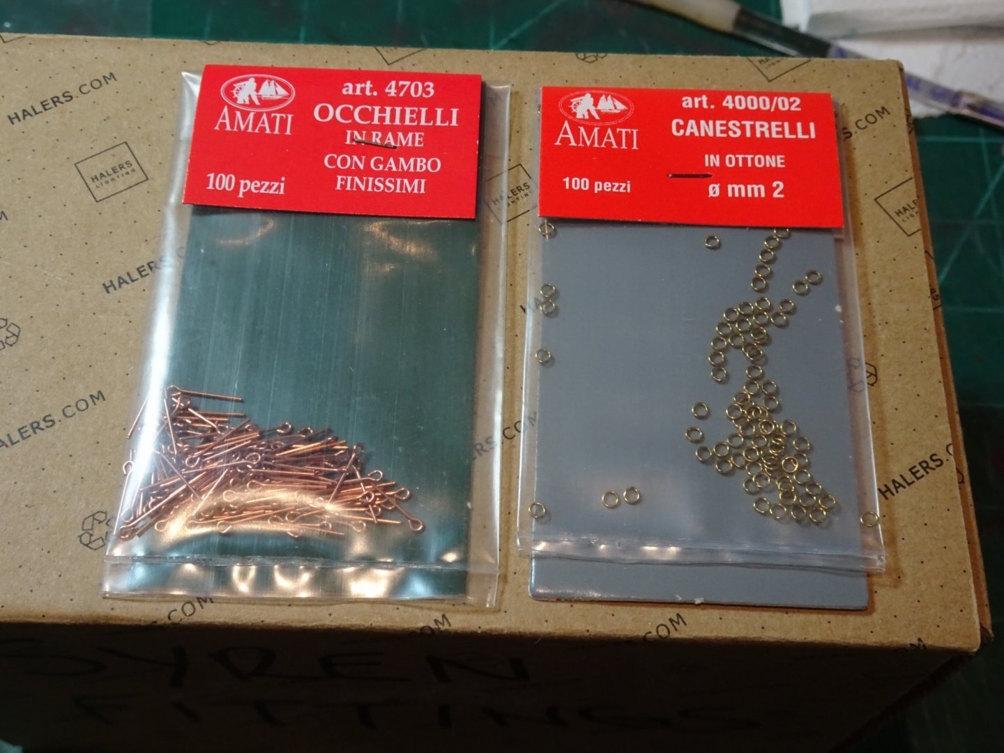
Hi Jacek, These are the measurements applicable to 9 pounder guns. The Breeching rope is 4½" circumference equating to 0.56mm ø at scale. I will be using Syren 0.63mm line for the purpose. The Breeching ring is 3” in the clear = 1.19mm. The ring thickness is ⅞”ø = 0.34mm at scale. The Amati 2mm rings are close to these dimensions. The loops are ½”ø thick, (0.19mm) and 1½” in the clear (0.59mm) The Amati eyebolts are close enough for scale, but need a slight tweak to make them loops rather than eyes. These figures are taken from The FFM, David Antscherl, and The Arming and Fitting of English ships of War, Brian Lavery. Chris is not a great fan of rigging guns, but the manual does provide details of blocks and line sizes. If following the manual advice I would go for the larger 0.75mm ø line to provide a nice contrast with the 0.1mm tackle lines. The provided carriage eyebolts are too thick, and are flat rather than rounded, as a result of the etching process. In reality this matters little in the overall scheme of things, very little will be seen of the gun detail once the Gangboards are in place, but the pedant in me drives me on.🙄 Hope this helps. B.E.
- 857 replies
-
- 4
-
-
- Sphinx
- Vanguard Models
- (and 1 more)
-
Blimey Glenn, I expect to add around £100 in additional stuff for my build but I think you'll hold the record for the most expensive Sphinx build on MSW. B.E.
-
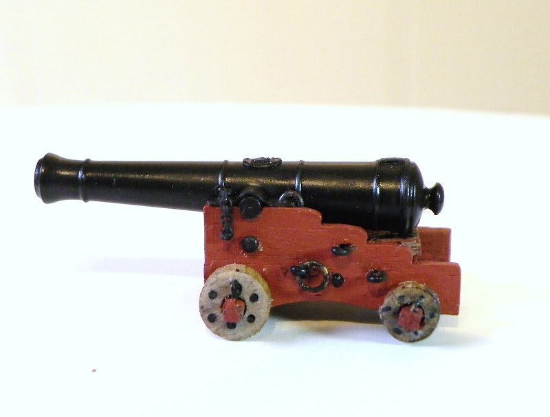
Thanks for your input guys, as a weathering novice it’s all useful stuff. @ Bob – re the wheel axles – it only requires the slightest touch on the corners, I will do it even less on the other guns. @ Thuky – with these particular guns once they are secured between the carriage brackets there is no need to touch them again, or even during fitting. Held on a cocktail stick they can be fitted untouched by human hand, or in Jacek’s case a catspaw. @ Jacek – They don’t look quite as weathered from normal viewing distance but a spot of extra buffing will remove any residual rust. -re the carriage iron work – For the ring bolts I used 2mm eyebolts and 2mm brass rings. The eye of the eyebolt was reduced in size a fraction and closed around the ring. For the loops I use the eyebolts set slightly into the carriage side. As fitted on a Pegasus carriage I also used the same approach for the tackle rings and bolts on the bulwarks. B.E.
- 857 replies
-
- 8
-
-
- Sphinx
- Vanguard Models
- (and 1 more)


.JPG.b8844b44fa344c5f01a49406d216fc5f.JPG)
.JPG.d255672a1f6b3698fec17c69261085f7.JPG)

.JPG.e846102fb0f524a09c15d61ac644b56b.JPG)
.JPG.2e4fa7216d2fefcb6616e37d301d5401.JPG)
.JPG.6901627bea663ab45f1c5ef8783614dc.JPG)
.JPG.05fe1f5774a126d47b2d4d794179d3d9.JPG)

.JPG.4d8ab60bbb67241be696a0e0ff91e96c.JPG)
.JPG.610a954462dc76318f8c5e911369b229.JPG)


.JPG.8245246ccecfeebd52a638243c77fed6.JPG)
.JPG.cb2c0425098cc61792edcecd5dd81582.JPG)

.JPG.388ca03804530e114f378732e36a5240.JPG)
.JPG.5167fad6f2590a508e22793d0c5bd352.JPG)
.JPG.6b46a62e224ebe588330169a1aeeea82.JPG)

.JPG.37c07e519bccb7fb31b108e7af2dccd4.JPG)
