
.JPG.ca33079f5815b861e67b9c2cccd37982.JPG)

Blue Ensign
-
Posts
4,564 -
Joined
-
Last visited
Content Type
Profiles
Forums
Gallery
Events
Everything posted by Blue Ensign
-
 Thank you Chris, my stern frames are now fitted, it's the stem piece (21) that's giving me some concern. Regards, B.E.
 -
Welcome Caspar, a beautiful boy you have there Nils. We too have never been able to go for long without a canine companion in the house, as you say Nils they bring such joy to our lives, despite the sadness we feel when saying goodbye to old friends. B.E.
-
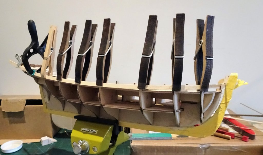
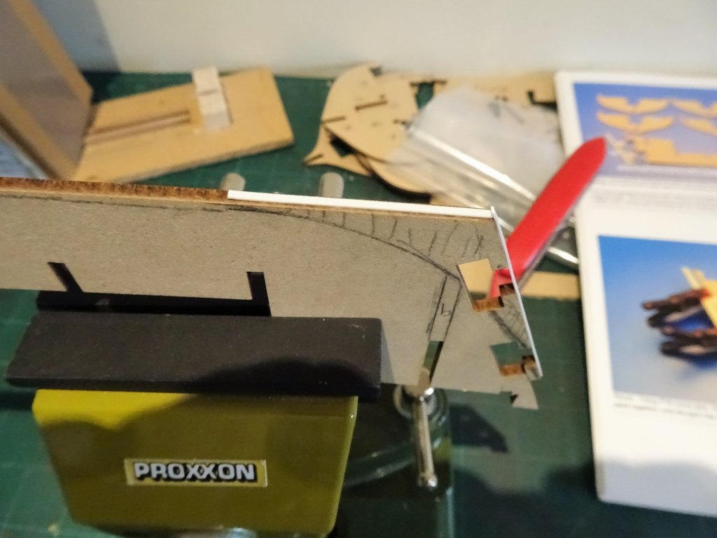
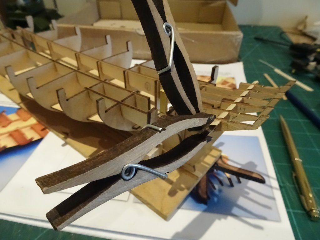
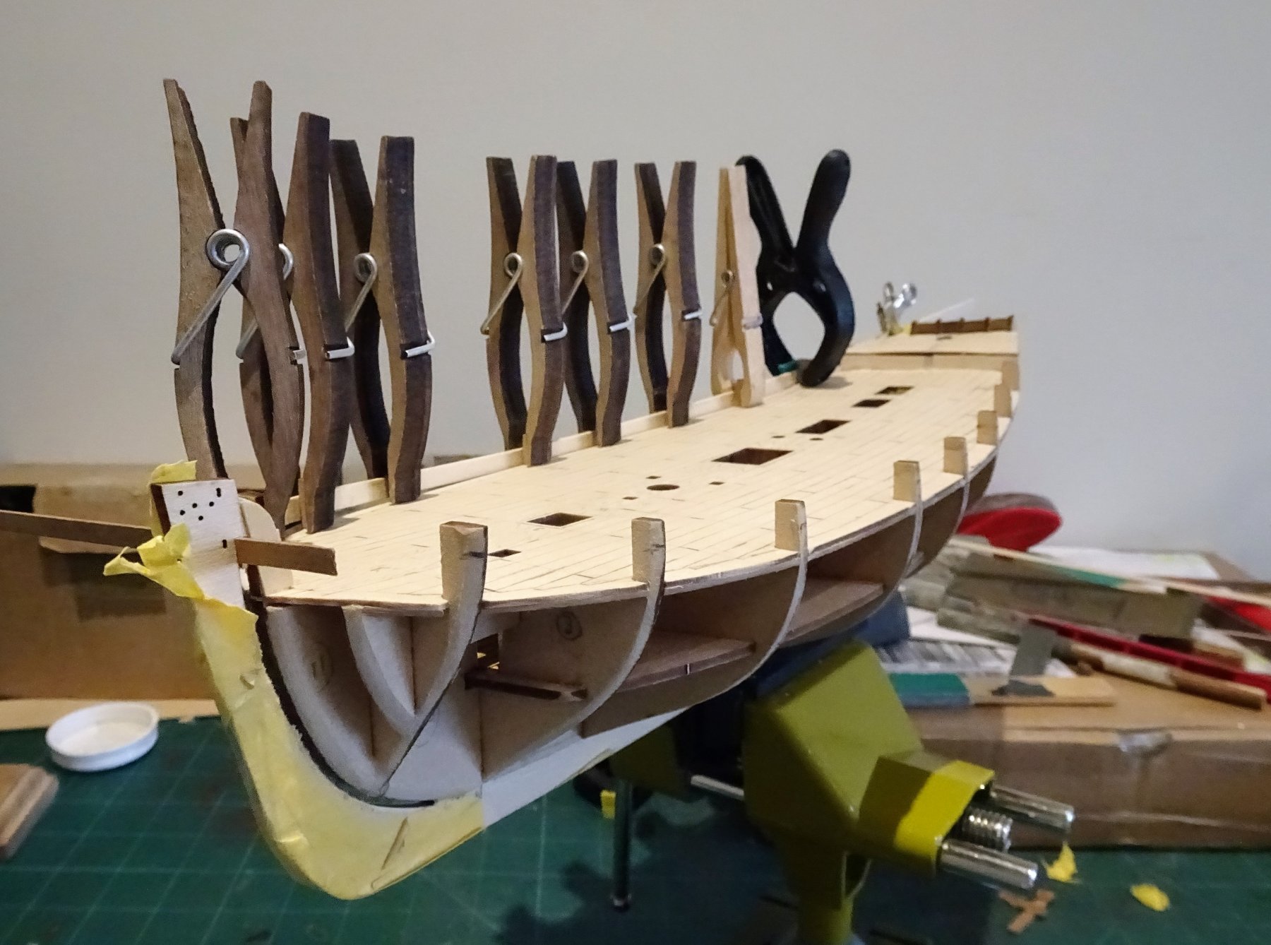
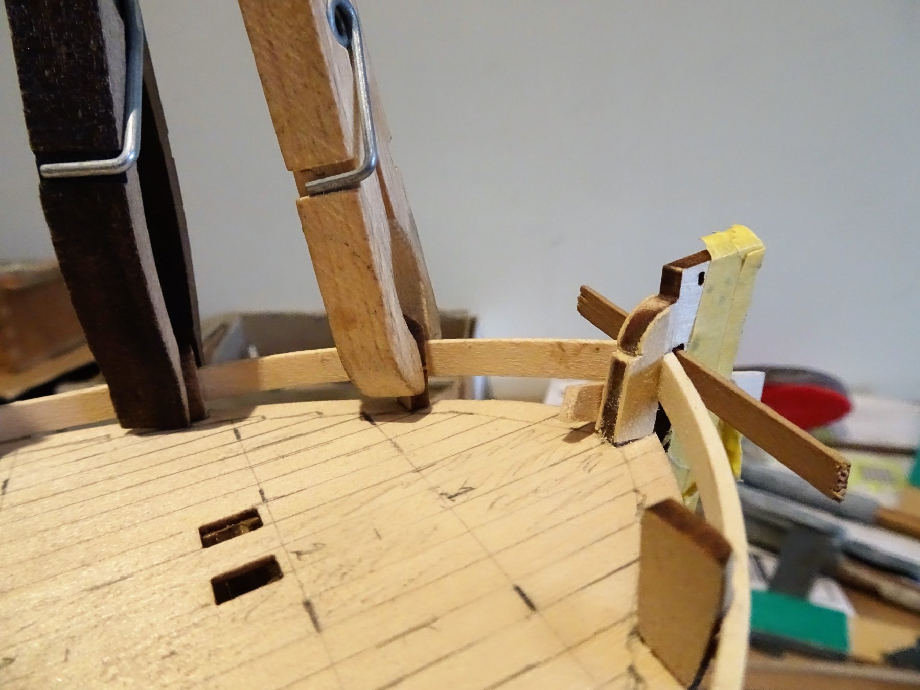
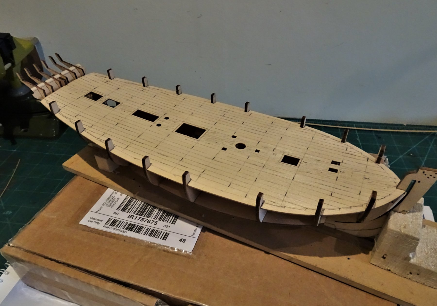
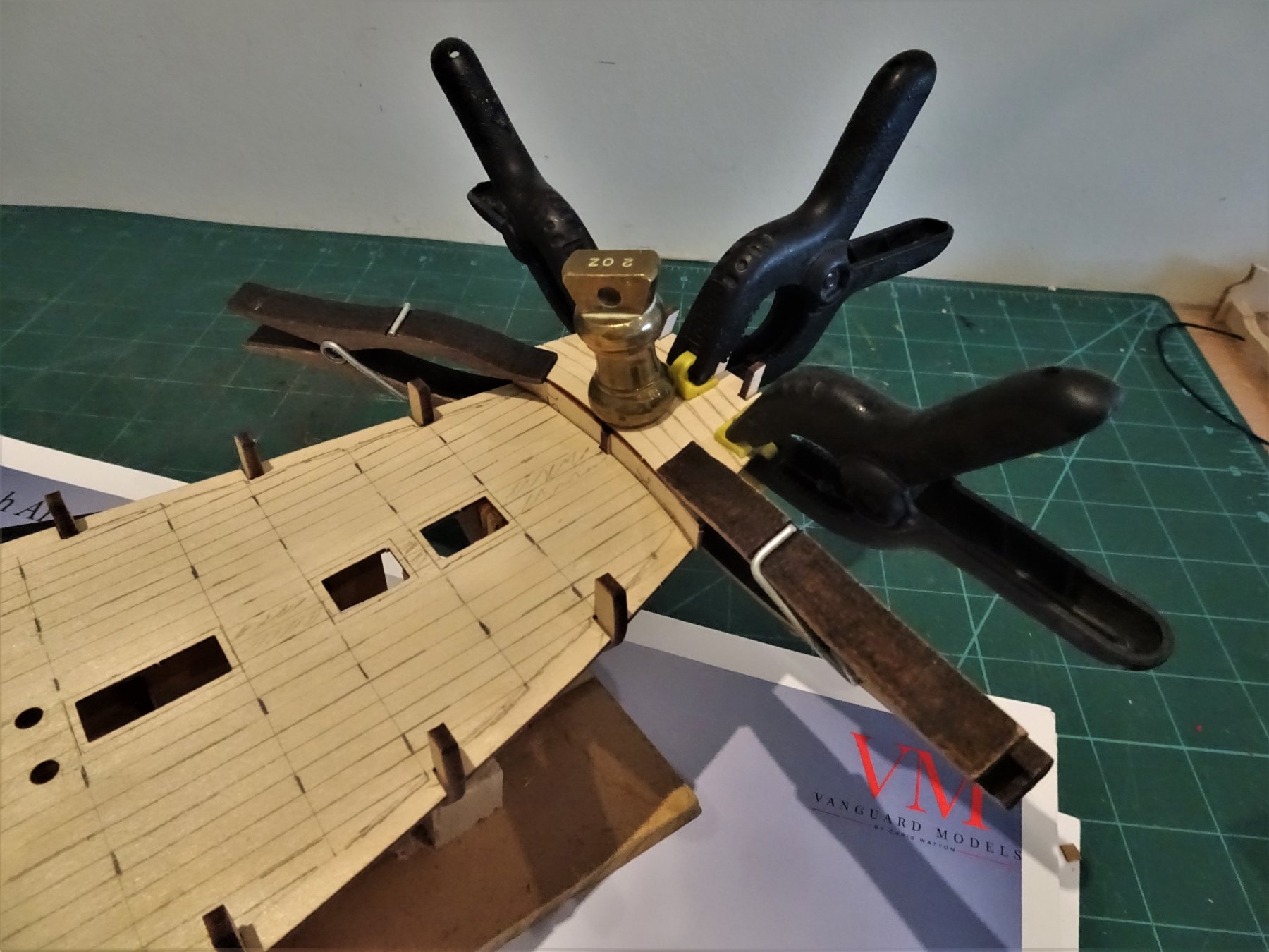
Post 5 That fairing business. With the underside of the deck strengthened I can now proceed to fairing the bulkheads. This is one of my least favourite ship modelling jobs, and I never seem to achieve full satisfaction with my efforts. It is however so important as a basis to get the subsequent planking right. These are fairly thin bulkheads so a reasonably gentle approach is required, no bashing away with a coarse sanding stick. These are a fraction of the size of the Cheerful bulkheads and there are less of them. I did wonder if an additional bulkhead might have been appropriate between bulkheads 4 and 5 just forward of the mast hole. I may resort to filling this area along with bow and stern fillers. The first plank of 1.5mm x 5mm lime-wood runs along 4mm below the tops of the bulkhead extensions. 578 In practice this is quite a tricky plank to fit; it needs to be both edge bent to follow the sheer, and have a curve at the bow end to fit into the rabbet slot. 583(2) This first planking is quite substantial and I used water and heat to induce the necessary shape. The induced curve for the bow rabbet is particularly necessary due to the inherent weakness of the stem piece, specifically at the top end of the rabbet /slot. Failure to take sufficient spring out of the bend around the bow will stress the stem and any flex may result in a split along the horizontal grain of the 3mm wood. 581 To counter this I added 0.5mm Boxwood strips to the inner sides of the stem above the deck. In my view it would have been better if the stem slot were a true rabbet, or the stem made of better quality timber, but kits have compromises. On reflection I should have re-cut the stem out of Boxwood sheet. 582 With the plank pre- shaped pegs are sufficient to hold it against the bulkhead, only one pin required at the aft end. 595 Attaching the Port side upper strake. A strip of wood is inserted between the plank and the stem in the slot to hold it hard against the after edge while the glue dries. It also protects the slot for the second planking. The second strake below also requires the heat and water treatment to take the stress out of the bow curve and sheer. Pinning as well as glue are necessary for this strake. During fitting, as feared, the stem did give way along the grain line on the inboard side at the top of the slot. 606(2) I re-glued it but now a clamp is attached to hold it in position during strake fitting. 604(2) 611(2) I did not taper these first strakes. 605(2) With the first two strakes in place the hull is now quite rigid, but be careful with that stem piece folks. B.E. 02/07/2019

.thumb.JPG.00f64b971e0ee0c1dbd59bd2a6397260.JPG)

.thumb.JPG.8923762783d19d36936655152d75e0eb.JPG)
.thumb.JPG.9c1dbd689744135b30885dfa44ee5d62.JPG)
.thumb.JPG.60d9b0906f557ec2f496c965740ea813.JPG)
.thumb.JPG.863a59d1a4d133d951c0dc9e9fb669f8.JPG)
- 335 replies
-
- 18
-

-
- alert
- vanguard models
- (and 1 more)
-
The deck plan and profile drawings held by the NMM refer to both Alert and Rattlesnake of 1777. These were sister ships designed by John Williams to the same specification and both launched within a week of each other. There are other layout differences in the Cole model; he has switched the positions of the Main ladder-way and the glazed Companion-way over the Captain's cabin, this he seems to have taken from the layout of the Hawke model in the NMM. Incidentally the Hawke model has the fore hatch on the centre line. I think I will stick with the layout as per the kit and the Goodwin book. Regards, B.E.
- 335 replies
-
- 2
-
-
- alert
- vanguard models
- (and 1 more)
-
I would have to think long and hard about raising the platform, it presumably has implications for the transom. Not at all sure about moving the Fore hatch, the Admiralty plan of Alert and Rattlesnake show the hatch in the normal position. I wonder if Roger Cole is guilty of applying 20th century thinking to 18th century practice. We had the same thoughts about the side ladders and chase gun ports with regard to Cheerful. In the end I overcame my instincts and went with the plan as per Chuck. Moving the hatch should be a fairly simple, and in the scheme of things such minor structural features don’t make much difference. Who’s going to know apart from you, me, and members of MSW.😀 Cheers, B.E.
-
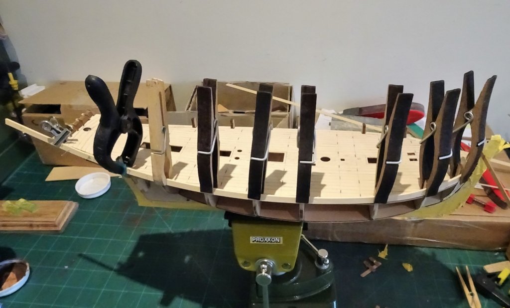
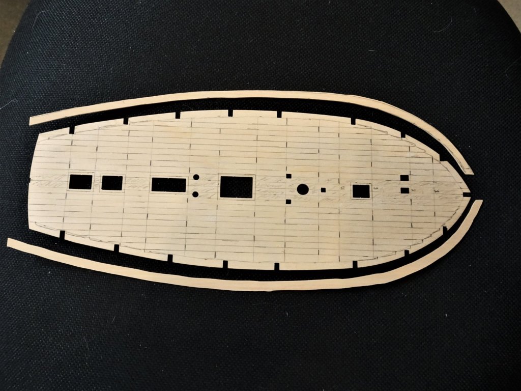
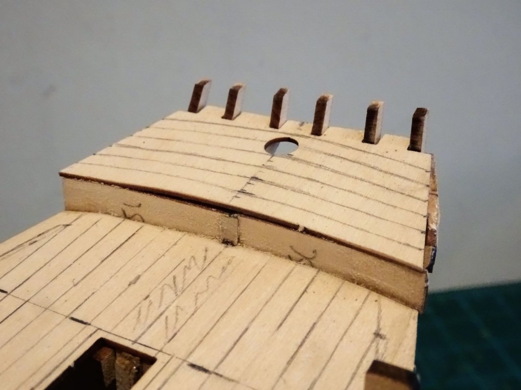
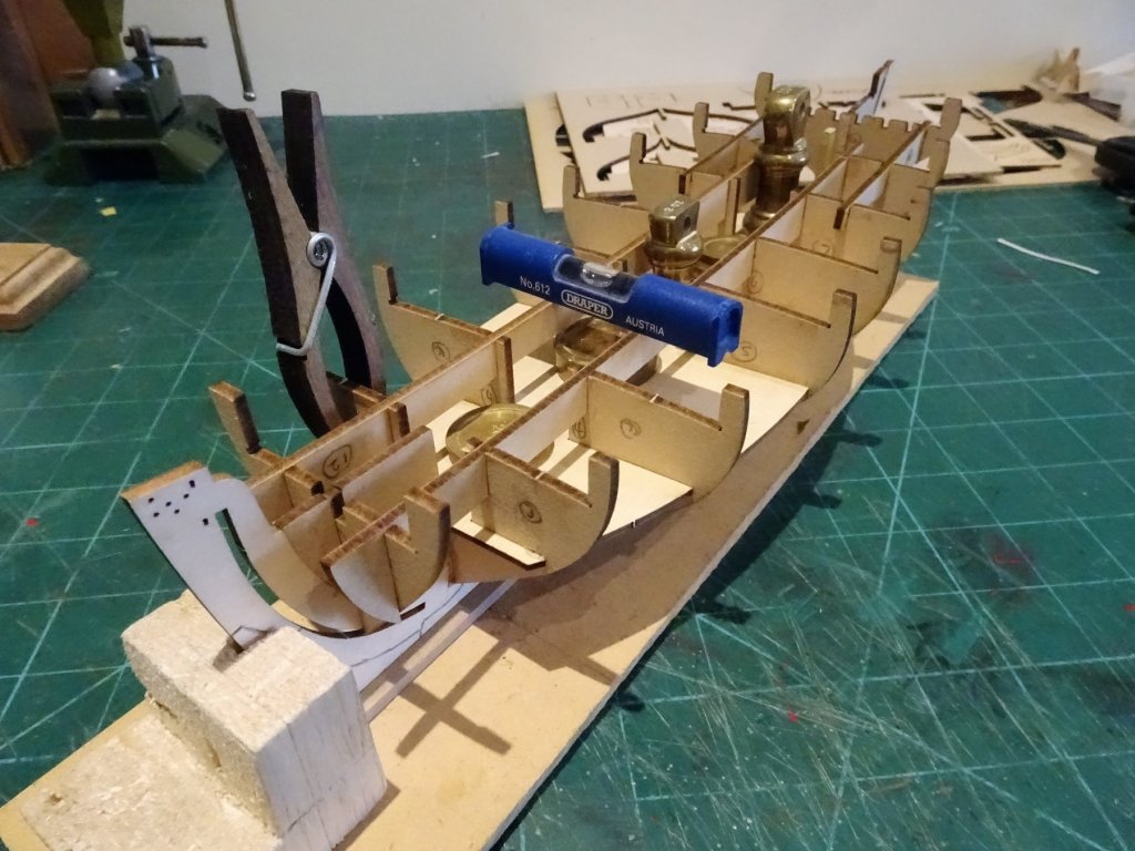
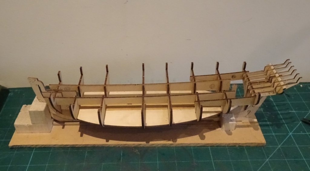
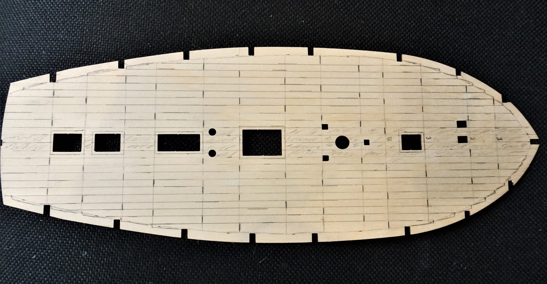
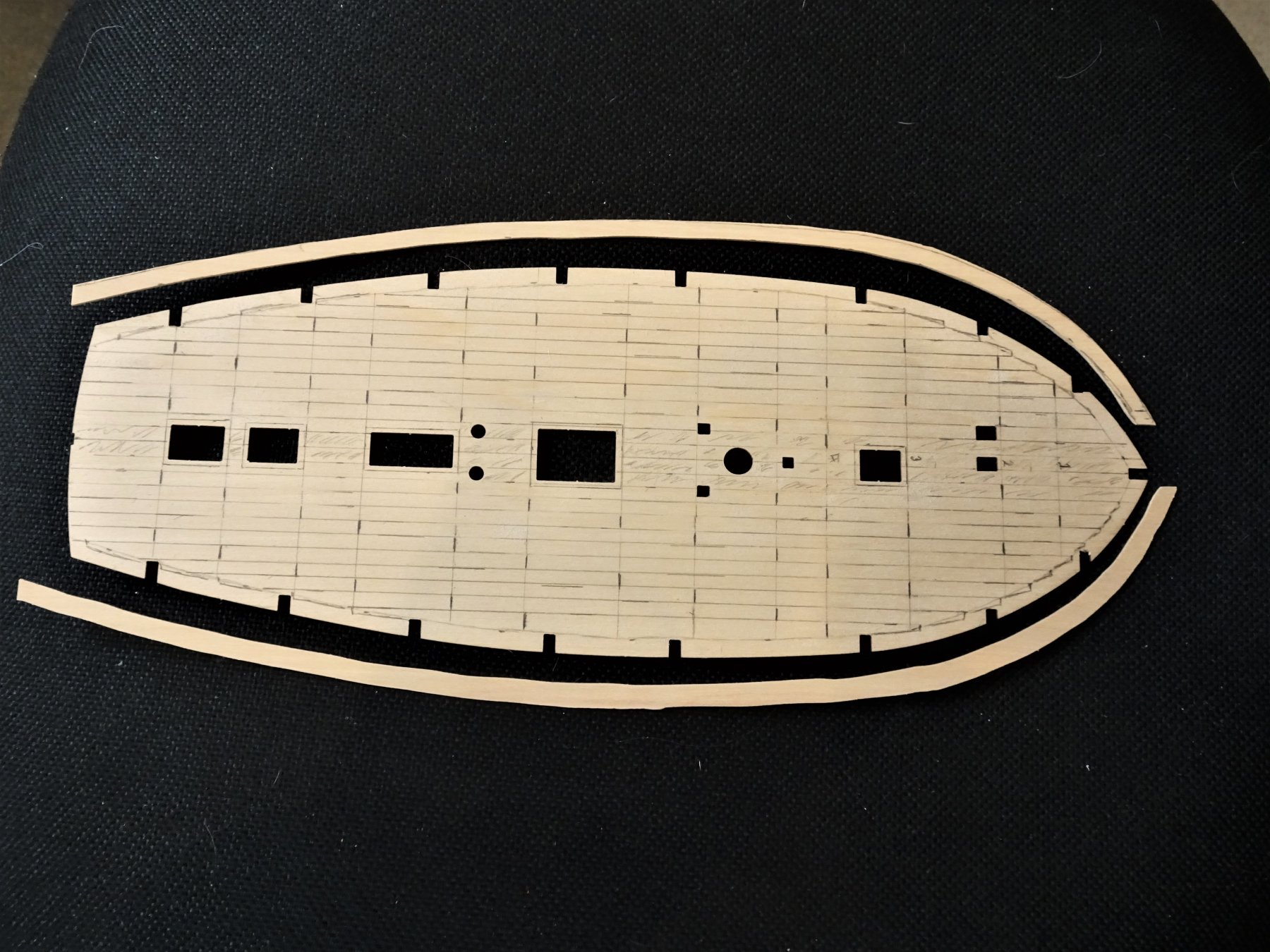
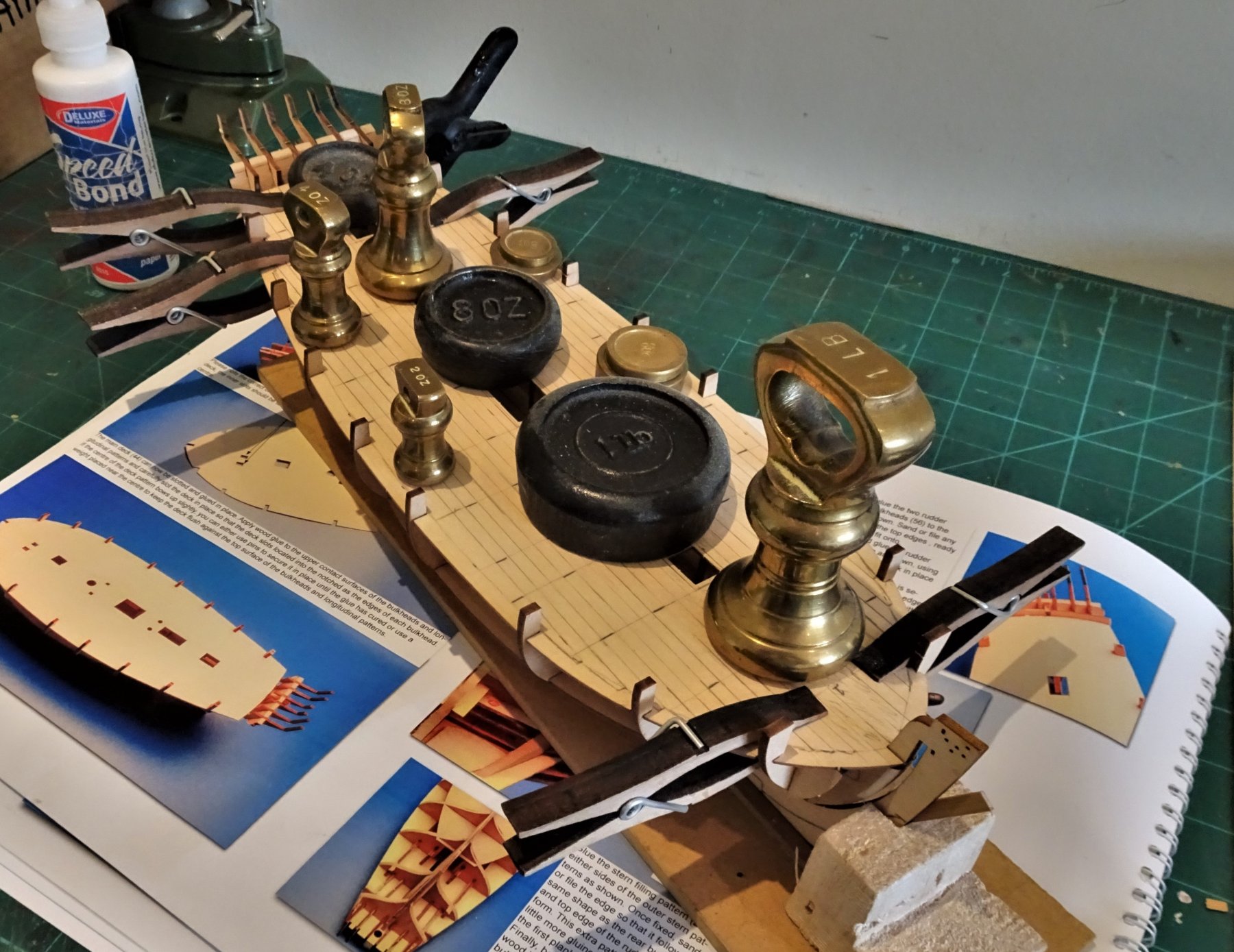
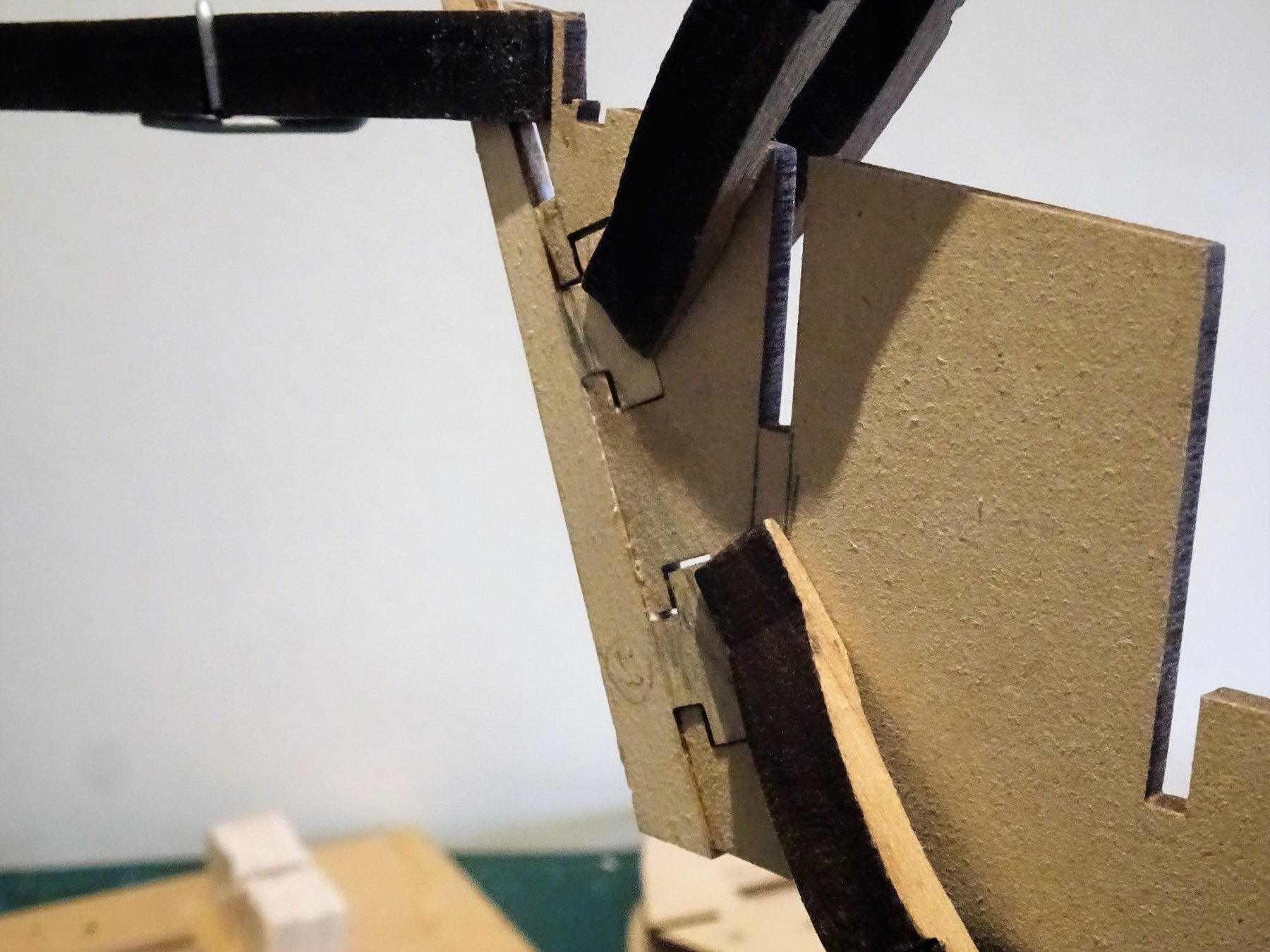
Post 4 Thinking about the deck My preference is to make several outline templates drawn onto card sheet. These will be used to mark out the planking pattern and use as a template to form the margin plank. The first thing to decide is the position of the deck beams. For this I have used the Goodwin book, and my main concern is not to have a butt ending up at an incorrect point such as mid way along the main hatchway where a main beam would in practice not be. I will be using a three butt shift with scale planks around 20' with shifts of around 5'+. Each plank within these constraints will of necessity have minor adjustments to take account of the closest appropriate beam. Using standard repeated one length planks would result in the butts appearing at unlikely places. If you're not over fussed by such considerations you can't go far wrong using the Deck planking article by Ulises Victoria in the MSW database, which I used albeit in a modified form. I start with planks each side of the centre line, and planks wholly within the spaces between the deck encumbrances will have no butts as the lengths are within the maximum. 484 After some trial and error I eventually got a pattern I was happy with and this was transferred to the false deck. 489 At this point I also rough cut the margin planks using Boxwood sheet. Once the false deck is in place I don't think it will be easy to remove. It is fairly flimsy (of necessity) and there are notches on the bulkheads which will lock it into place. 490 Having said that, handled carefully it fit quite easily, the hardest part is applying pva over the whole framing, and setting the deck before it started to dry. Handy to have a good supply of weights available. 494 The deck edges may be a little vulnerable to breakage during the fairing process so I think I will beef the underside up a little with strip wood. The final addition in this section is the Platform deck over the rudder housing at the counter. 525 This slotted easily into place and does provide some support for those delicate stern frames. 532 The facing panels fit neatly into the frame slots. 531(2) Temporary support blocks are inserted between the stern frames. 529(2) This completes the initial assembly stage, mostly painless, but watch out for those stern frames. B.E. 29/06/2019


.thumb.JPG.017f381c884873453c15455b0f118180.JPG)
.thumb.JPG.b23381f06c11d7d07247179d9b391d3f.JPG)
- 335 replies
-
- 18
-
-
- alert
- vanguard models
- (and 1 more)
-
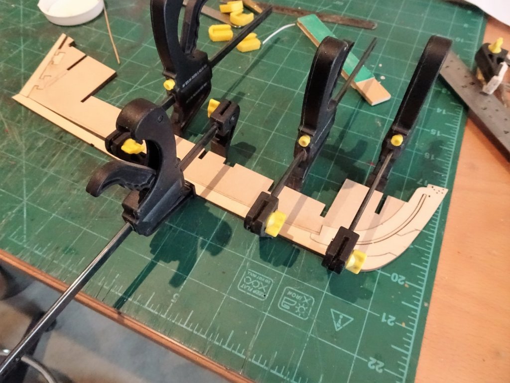
I bought them Kurt, I want some more but for the life of me I can't recall where I got them. They are really good for gentle but secure clamping, far better than the household clothes pegs readily available, which I tend to use when I want to form them to suit a particular holding job. If I ever discover where I got them I'll let you know. B.E.
-
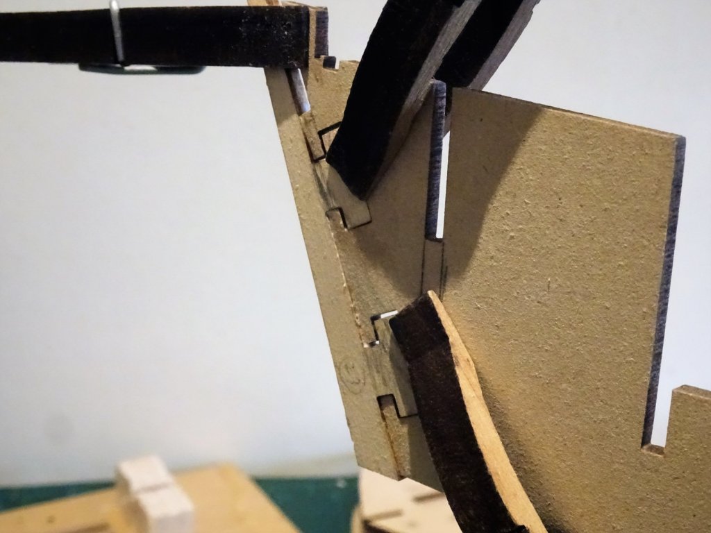
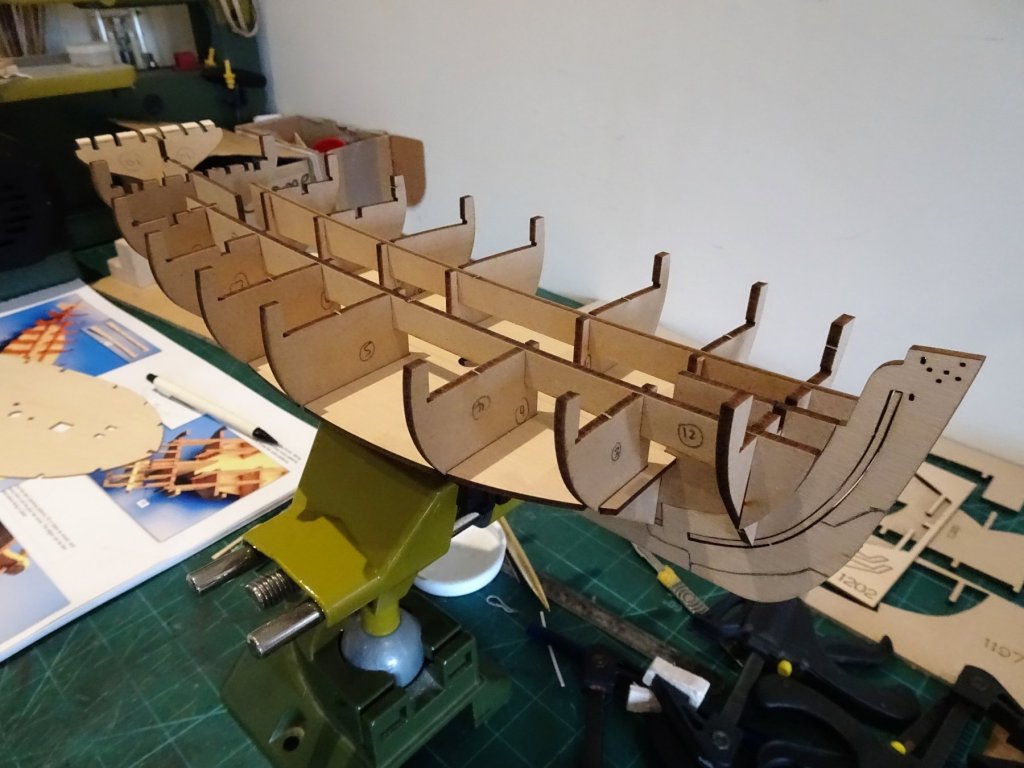
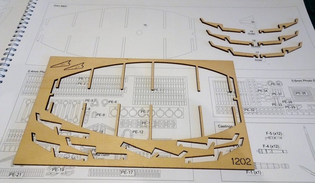
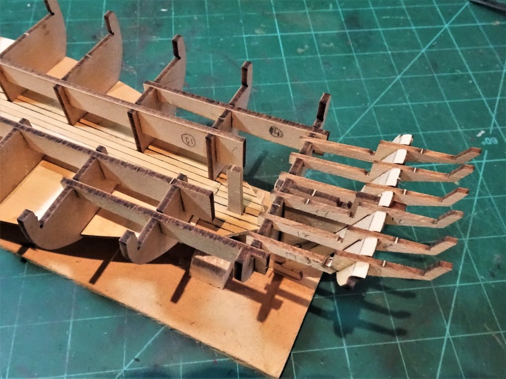
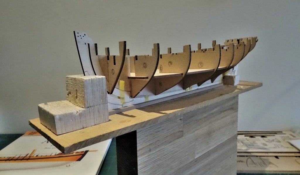
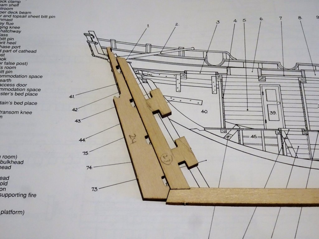
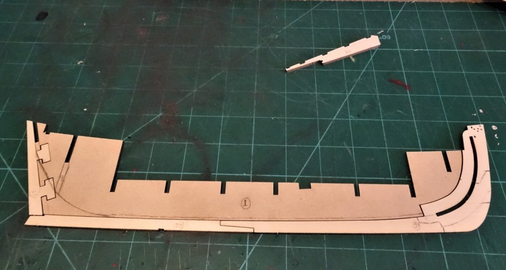
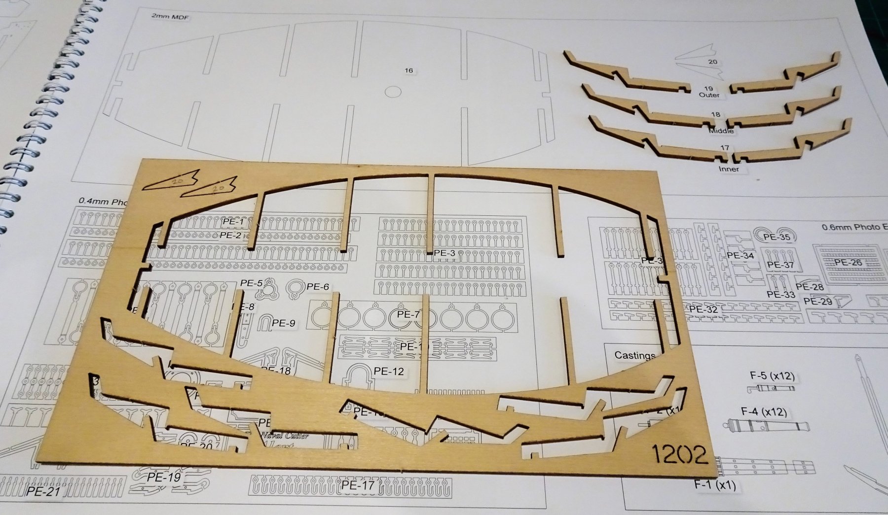
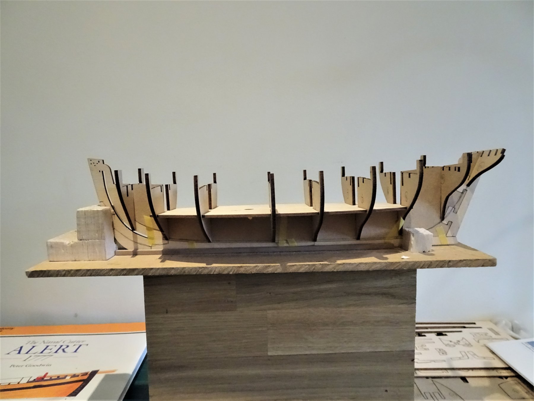
Post 3 Assembling the skeleton. Preparing the false keel I have marked the bearding line and attached a strip of 0.5mm x 1.5mm styrene strip along the area to gauge the required 0.75mm each side reduction. 354 According to the instructions the keel and stem are not attached to the false keel until all the bits that make up the basic frame are completed. I think it is easier to attach and clamp the stem and keel to the false keel flat on the bench rather than with all the bulkheads in place. 358 With the keel and stem in place the model is also better supported on the building board. Once secured I added the stern post which slots into the false keel. 357 It is quite a loose fit and the tabs need to be glued down against the lower slot to properly align with the keel. 364 The whole thing was then reassembled dry to check the fit before applying pva to the bulkheads and inserting the lower deck. 369 Whilst the glue was setting I temporarily fitted the longitudinal securing patterns to align the bulkheads. The system of a slotted lower deck and securing patterns negate a lot of the work otherwise involved in ensuring the bulkheads are both square to the keel and vertical, so the initial assembly is fairly rapid on this build. To complete the main skeleton filling pieces* are added at the bow and stern. * if you pre-attach the stem it helps to fair the edges of these fillers before fitting. The final part is attaching the rather delicate stern frames. The fragility of these fills me with some trepidation. 374 A point to note. On my kit the frames which come in three pairs were not placed on the holding sheet in the same configuration as in the build manual part identification drawings. As they are slot specific the parts need to be removed and checked against the drawing before numbering them up. I would advise test fitting these very gently before gluing them into place. Even so I snapped one of the outer frames during this process. 375 One other point to note is that on my build all the stern frames are at the same height, the manual build photo's at this stage appear to show the two inner frames (17) lower than the others? 382 In common with my other builds I do like to have a glimpse of the lower deck thro' the various hatches/ companions etc; so I have indulged a little kit bashing to facilitate this. Totally unnecessary but it's one of my little foibles. 384 The next given stage is to fit the Upper deck, but I think I will consider fairing the bulkheads first, besides I want to plan out the presumed beams and planking pattern before proceed. B.E. 26/06/2019
- 335 replies
-
- 23
-
-
- alert
- vanguard models
- (and 1 more)
-
I am at that stage Kurt, and have already noted the issue about the stern frames in the post I am shortly to make; I snapped one during fitting but managed to repair it insitu. Sorry you have experienced such an attrition rate they are very delicate and tricky little beggars to fit. B.E.
-
A very attractive model Tim, well done 👍 B.E.
- 115 replies
-
- 1
-
-
- Scottish Maid
- artesania latina
- (and 1 more)
-
Thank you Dave, I believe it is called the Square sail yard, which carried as indicated a large square sail, the equivalent of a Main sail on a square rigger. The Topsail attached to the yard below( the spread sail yard) at the clew The Topsail had a very large roach to it so it didn't cover the square sail to any great extent. Not something that will worry me, I'm strictly a bare stick man for full hull models. Cheers, B.E.
- 335 replies
-
- 1
-
-
- alert
- vanguard models
- (and 1 more)
-
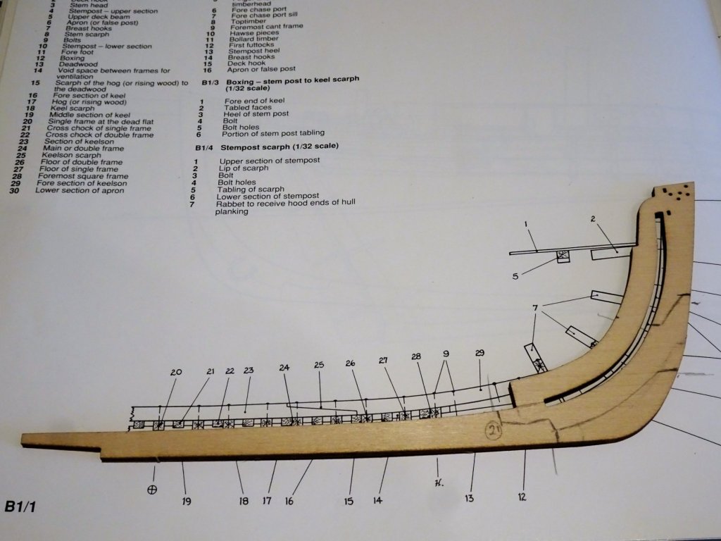
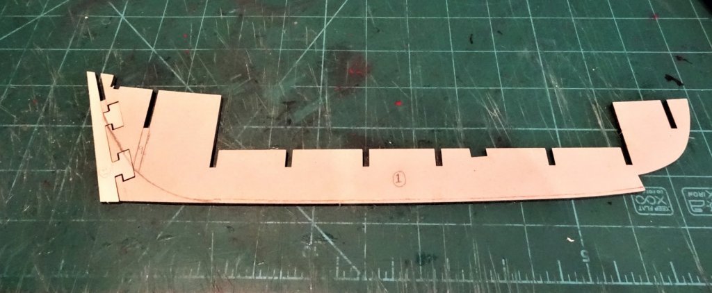
Post 2 Getting to grips First thing to note is that the part numbers are not laser cut into the mdf parts. It is necessary to mark all parts with the reference number before removal from the host sheet. 336 When starting a kit I like to dry fit the parts to get a feel for the build, and make up a simple build board to support the stem and keel. On my kit the bulkhead parts and the false keel are quite a loose fit so great care will need to be taken make sure that the bulkheads remain square during assembly while the glue dries. 338 The lower deck which slots over the bulkheads helps to stabilise the bulkheads square to the keel, but still allows some movement in the vertical plane. The stern post fits loosely into slots on the false keel and is glued into place, but before this can be done the instructions say to reduce the stern area to half its thickness to allow for subsequent planking to fit flush against the stern post. The actual area of the stern to be reduced is indicated as relating to the very aft edge of the false keel and the tabs attached to the stern post. 347 A specific bearding line has not been indicated, but I have drawn one in for the purposes of my build. 348 Altho' there is a long slot down the stem piece which in effect is the rabbet for the bow planking, the set up doesn't seem to lend itself easily to a keel rabbet to secure the Garboard plank. Any such rabbet would need to be cut along the actual keel leading up to the stem slot. There is only a 3mm width of keel to play with so any rabbet would have to be fairly shallow and would inevitably reduce the gluing area to the false keel. I think faying the Garboard strake into the keel is the safe option. 345 It is interesting to note that the stem, rudder post and rudder are quite close to the 1:64 scale drawings in the Goodwin book. 343 I will scribe the section joins that make up the stem as indicated in the Goodwin book, onto the kit provided stem. I had considered reproducing these items in Boxwood, but as I intend to paint the stem this would be a waste of good timber. B.E. 23/06/2019

- 335 replies
-
- 20
-
-
- alert
- vanguard models
- (and 1 more)
-
Post 1 I shall be building this model primarily using the following external reference sources. 1) The Naval Cutter Alert 1777 Book by Peter Goodwin. 2) Alert Provenence and Construction by N. Roger Cole. 3) Articles from the NRG journals Vols 44 and 45 by Roger Cole. 4) The Elements and Practice of Rigging and Seamanship by David Steel 1794. Thanks to Greg(DVM) for the link to the Alert article by Roger Cole, and to Kurt for the NRG articles in Vols 44 and 45 regarding clinker planking and coppering over clinker. I will also draw heavily on the approach taken by Chuck, and followed by me, in relation to the Cheerful build. I am also appreciative of the examples relating to Clinker planking provided by Dirk (dubz) in his Sherbourne build, and Nils (mirabelle61) for his Zeesboot build. There will be modifications along the way both in materials and fittings and these will be covered at the appropriate point in the build. Time to get the basic skeleton assembled. B.E. 22/06/2019
- 335 replies
-
- 3
-
-
- alert
- vanguard models
- (and 1 more)
-
Thanks for the heads up Kurt. 👍 B.E.
-
Cheers Guys, @Chris - between you and me it's beyond my pay grade too.🤔 @ Dirk - Thanks for reminding me about your sweet little Sherbourne build, I thought I had seen an example of a cutter clinker. 🙂 I am leaning towards following your example, a first layer planking should provide a decent base to attach the second layer, and I do have a good stock of boxwood strip to allow for the likely errors to come. Thanks for the link to your build photo's, it looks like it will be my main reference work for the lower hull planking. @James - I don't think it will be a quick start🙂 @Steve, - I've been there too😃 Back to the head scratching. B.E.
- 335 replies
-
- 1
-
-
- alert
- vanguard models
- (and 1 more)
-
The Cutter Alert Build log The Alert kit arrived at a very opportune time for me as I'm fresh from my knowledge of cutters from my recent Cheerful build. Ever since I acquired (1991) the Peter Goodwin book The Naval Cutter Alert 1777. in the Anatomy of the Ship series, published by Conway Maritime press, I have long wished to make a model of Alert. Chris Watton has now made that possible, without having to scratch build everything myself. Before I start however, there are already things buzzing around my head, and points to ponder. Clinker or carvel planking below the Main wale? The kit indicates Carvel whereas Goodwin shows Clinker in his book but goes on to state that Alert was sheathed with copper at Deptford on 30 July 1777. How would this work, I've never heard of coppered clinker, can this be right? However, I'm tempted to look at clinker planking, but I've absolutely no experience of it or even how to begin, so it would be quite a challenge for me. If I do opt for Clinker I imagine one has to start from the Garboard plank and work upward to the wale. Should I go for a carvel base planking and clinker over the top, or go straight for a single planked job as with Cheerful. I may well think it's all too difficult, and build her carvel, but these are all questions I need to resolve before I reach that stage. In the meantime I have to get my build plan organised, which may be some time. B.E. 20/06/2019
- 335 replies
-
- 11
-
-
- alert
- vanguard models
- (and 1 more)
-
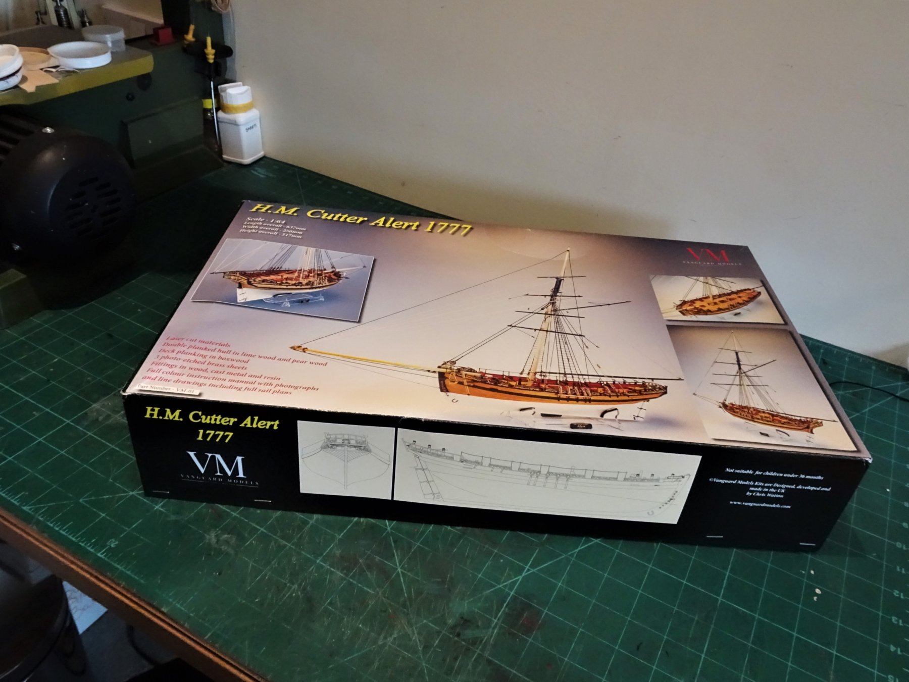
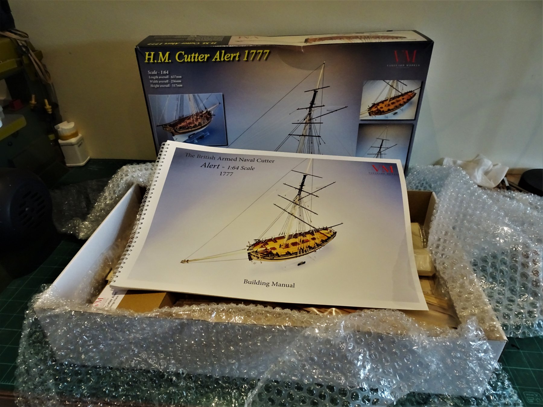
Not a long journey, in my case, a mere 76 miles, but my Alert has arrived, delivered by UPS at 2pm. Everything intact but I think it would save Chris some problems down the line if he does invest in a stronger box, the long sides gave little support to protect the contents. Not had chance to fully examine all the contents but the materials look good and I love the A3 instruction manual, beautifully produced, and what a bonus for my tired old eyes. Liked the touch of a personally addressed note inside the box.👍 Thank you Chris, I look forward to hopefully doing your Alert justice. B.E.


-
Hi Kurt, I don't think you will need epaulettes for your Alert commander. They weren't officially sanctioned by the navy until 1795, altho' some officers may have worn them some ten years earlier. Alert was lost in 1778 (taken by the French 17/7/1778) so it is too early for such 'Frenchifications', a much plainer uniform would apply. B.E.
-
Hello James, looking at your rudder have you got the strapping in the right configuration? You seem to have the pintles (on the rudder) below the gudgeons on the hull, which I don't think would work. B.E.
- 241 replies
-
- 1
-
-
- mermaid
- modellers shipyard
- (and 1 more)
-
Thank you all for your kind comments🙂 As a footnote to the completion of my Cheerful build, as with Pegasus I indulged myself with a photo build album. Today I received the Album. This particular one has 72 pages of 28 x 21cm full colour photo's produced by Vistaprint at a cost of £41.52 delivered. Regards, B.E.
.thumb.JPG.aae2ab08ef37c80d7132abcbb5061d5f.JPG)
.thumb.JPG.f8cc8b564c69ae7e0c02481d6207ea57.JPG)
.thumb.JPG.9831ec2a389a7248ddbf6d0497730f4f.JPG)
.thumb.JPG.f7ab2d06e0a4d96ea56feb82f68e5513.JPG)
.thumb.JPG.7f6707b050cba30b17c5785916ca3ee8.JPG)
- 574 replies
-
- 23
-
-
- cheerful
- Syren Ship Model Company
- (and 1 more)
-
Couldn't resist it Chris, order placed today, look forward to making Alert come to life🙂 Every success with your new venture. Regards, B.E.
-
Well done Michael on completing this testy little model, I like the dark red paint colour, she looks very nice. I didn't make a full case for my Pinnace, just ordered a plain acrylic cover to sit over it. Regards, B.E.
- 90 replies
-
- 2
-
-
- english pinnace
- Finished
- (and 1 more)
-
Nicely done 👍 B.E.


.JPG.9399f319a9020b59ef3a5663d174fcb8.JPG)
.JPG.32bbe35c2c2c07513aeb7fd60ba3ed6b.JPG)
.JPG.dcb49750252a37f868e99d2cf7f88364.JPG)
.JPG.490ba589ba656807a49fafb692b1ad2e.JPG)
.JPG.23794e0121d7c4f2dd3d0a4b37f09dca.JPG)
.JPG.d7c981afd4a15715681161307c34f212.JPG)
.JPG.97cfdd0e89838f0ea397236ae1daa52b.JPG)


.JPG.8f8bbfdd9051b73fae7ecd4365e31282.JPG)
.JPG.306c0b022014739485ca0adbdd749248.JPG)
.JPG.1caee52ac8b51903708da2788da261d4.JPG)
.JPG.56151df470a17bea13aed54205527552.JPG)
.JPG.d0ff6ba62be66d826526add87f7a929f.JPG)