Landlubber Mike
-
Posts
4,551 -
Joined
-
Last visited
Content Type
Profiles
Forums
Gallery
Events
Everything posted by Landlubber Mike
-
 Hi Carl, looks great. I forgot about the flag - I need to add that to my build as well. I've seen people use painters silicone caulk, clay and other similar materials. I think they make a snake of it, put it in the bottle, heat it, and then push a plug into the "sea" to leave a depression for the model. I ended up taking a different route because I didn't have the foresight to build a similar plug early in the build. So instead, I am using "Water Effects" from Vallejo - Atlantic Blue: http://www.vallejo-farben.de/water-stone/page/f10.html I glued the base in the bottle, then using a tiny putty knife with an extended handle, I dropped scoops of the Water Effects into the bottle, which has the consistency more of a thick paint than anything. It was pretty easy to work into waves. The big pain of it was then cleaning up the sides of the bottle where some of the material got on it. The whole process took me hours. I built up the sea around the base, and when it dries, I'm going to dry brush some green on it as well as some white for the spray coming off the boat. I'm not sure how it's all going to come out. Hopefully I built the sea around the base enough that when I seat the model on the stand, it looks like the water is against the boat. What I may do is drop some more right onto the base when I'm about to put the ship in the bottle, but at that point, I really will only have one shot to get the boat in and on the base properly. I found that the Water Effects takes a while to dry inside the bottle. I might use a hair dryer or something to speed things up, as it's still pretty viscous a week after putting it in. I'll let you know how it all goes.
 -
Jason's post reminds me that one thing you might want to consider when planning your planking run is to butt the planking against the hatches. It makes for a clean look, though it might be tough to butt the planks against the sides of the hatches if you aren't cutting your own planks.
-
I have to echo what SpyGlass said. I spent the time to reinforce the center line of my Pegasus and am very glad that I did. It didn't take much - just a few small pieces as you can see in my log. Adding the pieces will also help maintain the camber of the deck as you start planking it.
-
Nice progress. I ended up just planking the area under the fore hatch - I don't think you'll see much if any of the rest of the planking, but probably a little laziness on my end as well went into it. Good practice though. Just out of curiosity, what wood are you using for the planking? It looks like walnut, when I think the kit would have you use tanganyika.
-
Looks great Carl. I've been working on my Hannah the last few nights as well, and finally finished the rigging last night. I have to touch up some of the painted areas, but otherwise the ship itself is good to go. I still need to wait for the "sea" in the bottle to dry and harden, at which time I'm hoping to paint some highlights for the water and the foam around the ship. If you don't mind me asking, did you use the cauterize technique to attach the lines? I was really skeptical of the holding power of doing that, so I went with knots and glue. Also, have you tried the insertion tool yet? It's very fiddly. I'm a bit nervous about getting it into the bottle, especially with the sea that I inserted. I'm also wondering how easy it's going to be to get the masts upright and spars straight, and then tie off the two running ends. To say that the bottle opening is tight is a big understatement.
-
Thanks Eamonn, this is an effective technique and your results look great. Did you consider pre-treating the nails with liver of sulphur before installation? Just wondering, as I'm considering adding nail heads to my build but didn't know what the solution would do to the surrounding wood.
- 1,039 replies
-
- 1
-

-
- ballahoo
- caldercraft
- (and 2 more)
-
Tryworks came out really nice Bruce. The color for the bricks looks really good.
-
Looking great Bill. That's going to look amazing in that case! I don't know what I'm more jealous of - your woodshop or the fact that you don't have to do the DC commute any longer
- 335 replies
-
- 2
-
-
- Constitution
- Mamoli
- (and 3 more)
-
I would definitely use a mask when working with the MDF. The dust bothered me a little when I faired the bulkheads, particularly when I did my rough sanding with a Dremel. After reading stories about wood dust on here, I am taking a lot more precautions with my health.
-
Hi Glenn, thanks for looking in on my build. Sorry to respond so late - I was out of town on a family vacation, and the family brought home a nasty cold so I've had my hands full with a sick household. For the hatch coamings, I am following TFFM (The Fully Framed Model). The author says that the coamings frame consisted of the two pieces that ran fore and aft (the "coamings") and the two cross-pieces that ran athwartships (the "head ledges"). Essentially, the head ledges look like a "T" and the coamings look like an upside down "T". Looking at your Revised Gratings PDF, the side views in the second set of diagrams looks correct to me (assuming those are meant to show the "coamings." Note, however, that the plan view of the second set of diagrams is not correct - the head ledges, as a "T", should extend across the entire width and cover the coamings (hopefully that makes sense). If you really want to be 100% authentic, TFFM says that the ends of the coamings that join the head ledges have "half-lap joints that are tailed." TFFM goes on to say that "a tailed joint is angled somewhat like half of a modern dovetail, but is sloped in two planes." At 1:64 scale, I wasn't about to worry about that kind of detail. You can see my coamings in the second picture in the post of my log linked below (sorry, for some reason I can't seem to upload the picture directly to this post) - this is the head-on view of the head ledges: http://modelshipworld.com/index.php/topic/7267-hms-pegasus-by-landlubber-mike-amativictory-models-scale-164/?p=248121 Hope that helps. Good luck with your Pegasus - it's a fun build, especially with all the fellow Swan class builders on here and the wealth of materials out there to help you improve on an already impressive kit (the TFFM series, the NMM plans, etc.).
-
Looking great Carl. I'm at the rigging and attaching sails stage myself. I'm not a big fan of the included sails, as I would have preferred material that was pure white rather than material with lines. I might try substituting silkspan or modelspan, but I'm wondering if they will look really wrinkled when folded for insertion into the bottle.
-
Nice update Ian - your Unicorn is coming together very nicely. Your decision to open up the waist worked out very nicely. Too bad the stove will be a little more hidden, but you and your fans know it is there.
-
Really great build Peter, wow! Congratulations on your very fine work. You definitely set the bar high for the rest of us Swan class builders.
- 431 replies
-
- 1
-
-
- pegasus
- victory models
- (and 1 more)
-
Looks fantastic, great build and case! The pine moulding was a very good idea.
-
Wow, that's very nice work Mark. Coming along beautifully. How are you finding working with ebony? Will you use it again in the future?
-
Martin, that's some really nice work. I love the anchor stock planking effect, I'll have to try that out. Also, the carving of the last wale planks came out very nicely, wow. Glad you like the GF stain - it works very nicely in my experience. Have you thought about your overall color scheme for the upper hull? When I started this build I thought I would go natural for most of the hull except for black near the friezes, but now I'm considering going with dark blue (GF blue on pear) for the friezes area, redheart for the upper strip area, and black for the wales down to the copper line - framed by boxwood rails. Still debating whether to go with black from the wales down to the copper line, but I like Realworkingsailor pulled that off on his build.
- 467 replies
-
- 1
-
-
- fly
- victory models
- (and 1 more)
-
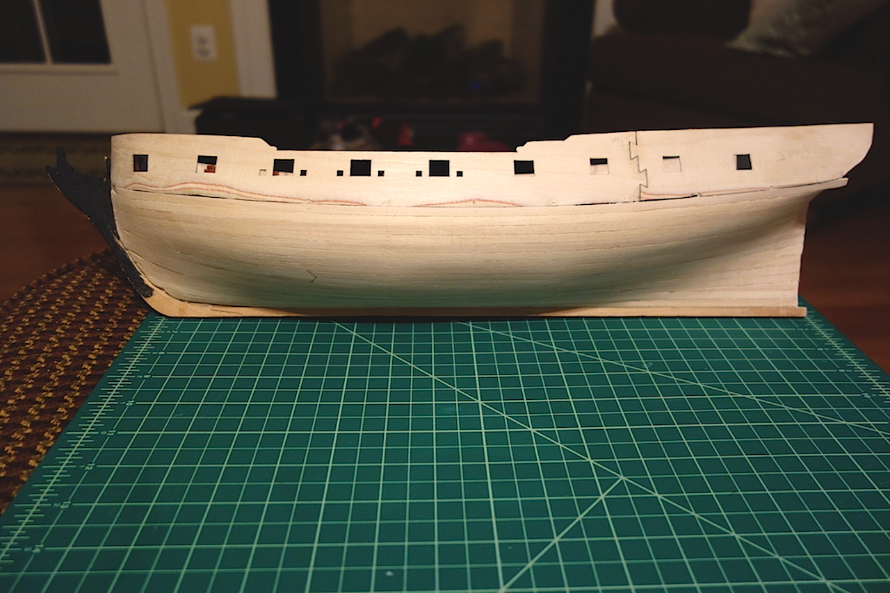
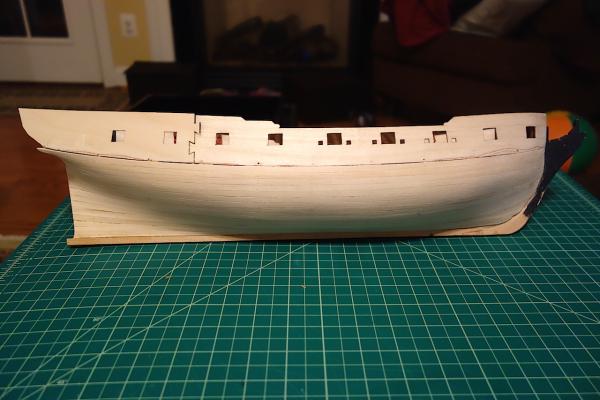
Thanks very much guys. Well, I was able to get outside to do most of the sanding on the starboard side. Thankfully temps hit 50 this afternoon, so I didn't need to wear mittens or glue sandpaper to my hands The starboard side came out pretty well, almost identically to the port side. Still need some filler in a couple of areas and need to fix the gunport patterns at the jigsaw connection and bow, but I'm really happy with how the first planking went. I have to figure out the stern area with the stern counter, as well as the rabbets. But like Martin said, it's nice to see the actual shape of the hull take form.
-
Mark, sanding while wearing mittens must have been an adventure The temps are supposed to hit mid-40s this afternoon and the sun is out, so it should be a little warmer. Otherwise, I'll have to wait until next weekend as I prefer to do it in the daylight and it's dark by the time I get home from work. I just want to get the majority of the sanding out of the way so that I can do the spot areas at home - when the Admiral is asleep Ian, gluing sandpaper to my hands is almost as crazy an idea as wearing mittens, but I'll keep that in the back pocket as a last resort measure SpyGlass, I think you're right that I don't need to fill every gap. There is one slightly low plank at the bow that I have to fill, and I'll have to fill that area near the gripe and likely up near the stern counter and stern post. Otherwise, the planking is very smooth without bumps and dips. At 1.5mm planks, there is plenty to work with to sand back to which is very nice. On my Badger, the lime was 1mm, and in some areas I came very close to sanding through the first planking because I didn't do as good a job laying the planks naturally. I have the Bob Hunt practicum, and he covers the entire first planking with filler, whether needed or not. To me that really seems like overkill, with the potential that the approach possibly could disrupt the some of the curves that the bulkheads give you. Based on the practicum, it looked like he didn't spend much time fairing the bulkheads, as he used a drum sander for most of them so maybe his approach is necessary. I spent probably close to 6-8 hours fairing the bulkheads, constantly laying test strips to make sure a smooth run - based on my results at least on the port side, I don't think I need to cover the entire hull with filler.
-
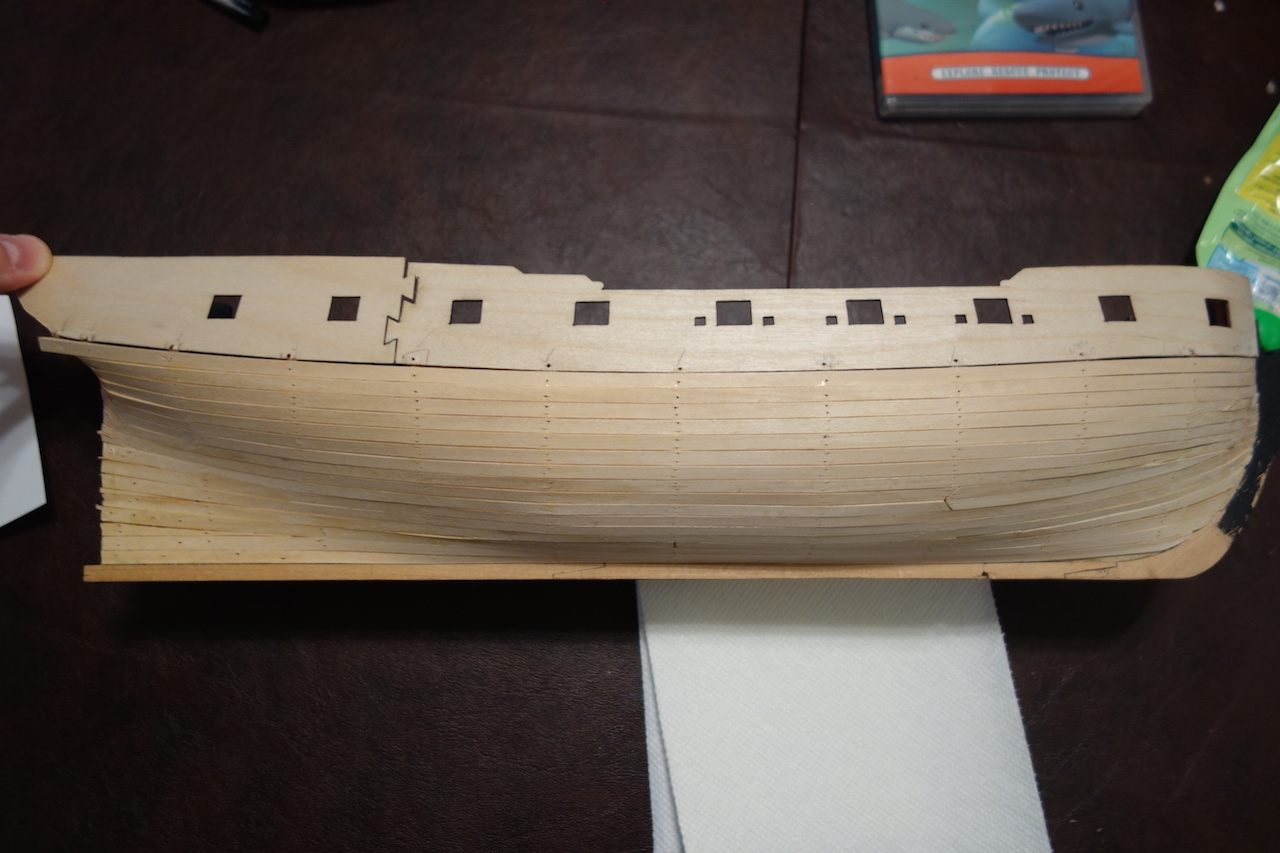
Well, the first planking is complete! Here are the pictures before sanding: Looks pretty rough, but things got much better after some sanding. I spent about an hour sanding the port side this afternoon sitting on my porch steps, but at 40 degrees (F) outside, it started getting hard to feel my fingers at the end (the Admiral just shook her head at me, but I reminded her that it was better than having the dust inside the house). Hopefully the weather will be nice enough tomorrow so I can get some work in on the starboard side. Spending the time I did in fairing the bulkheads seemed to pay off, as I don't think I'll need much filler. I mostly need some to close the gaps between the gunport patterns and the first plank, and a bit at the bow and stern. I cheated a bit on the garboard plank by simplifying it, so I'll also need some filler in the area that feeds into the gripe. Overall, I'm very pleased with how it's coming out. The Swan class hulls are very shapely, which are borne out in the Amati models.
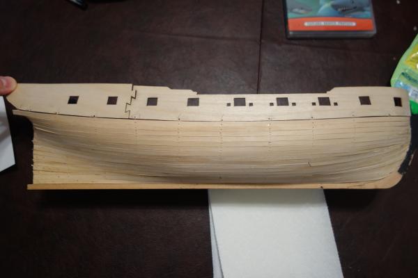
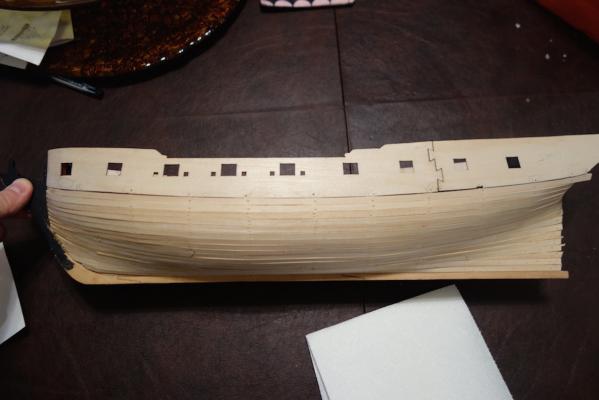

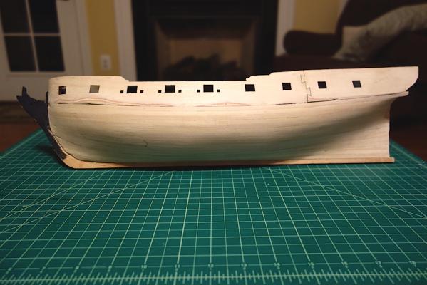
-
That's a nice really space Joe. A beer fridge, speakers and a flat screen TV and you'll have the perfect man cave.
- 302 replies
-
- 2
-
-
- granado
- caldercraft
- (and 1 more)
-
Hey Carl, just stumbled across your log too. Last year I started on the same kit and am at about the same stage you are. I'm planning to put "sea" into the bottle, which has been a little challenging to say the least. It's a fun kit, though I had issues trying to get the wrap-around photo etch around the hull.
-
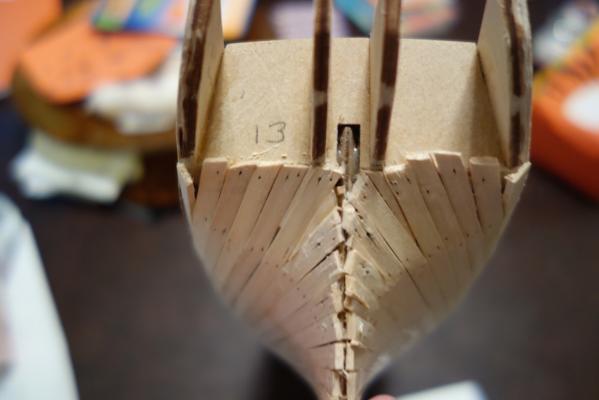
Hi Jason, looks great. I like how you stopped the first planking at the bearding line near the stern. I ran the planking to the stern post, but I have a feeling that I'll be sanding a lot of that off I also ran into similar issues planking my Pegasus. It was a little easier on my Badger where there were fewer curves, but I think spiling is the way to go where there are more complex curves in the hull (unless one is comfortable with pointed or up curved planks at the bow). I'll probably try it out on my Pegasus - Frank and others have assured me that it is not as difficult as it seems, so I'm going to take their word for it - and if it is too difficult, I'll send them my hull to plank If I mess it up, most will be covered with the coppering, so I might as well practice (I'm not coppering my Lyme, so it would be good to get some free practice in now).
-
Looking great John. Did you color the chains at all? I love the bronze look on some of them. How do you like the serving machine? I was thinking about getting one, as doing the serving with tweezers and clips on my Badger was not very fun at all.
-
Thanks Nick! I'll definitely check it out. I love your Le Mirage by the way