Landlubber Mike
-
Posts
4,541 -
Joined
-
Last visited
Content Type
Profiles
Forums
Gallery
Events
Everything posted by Landlubber Mike
-
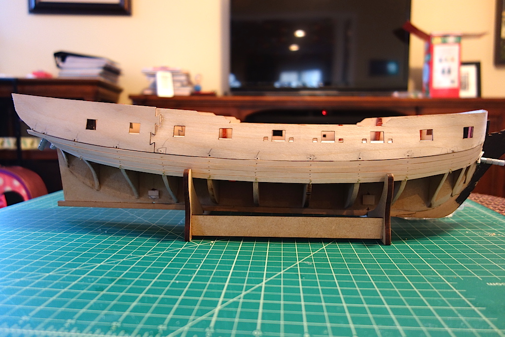
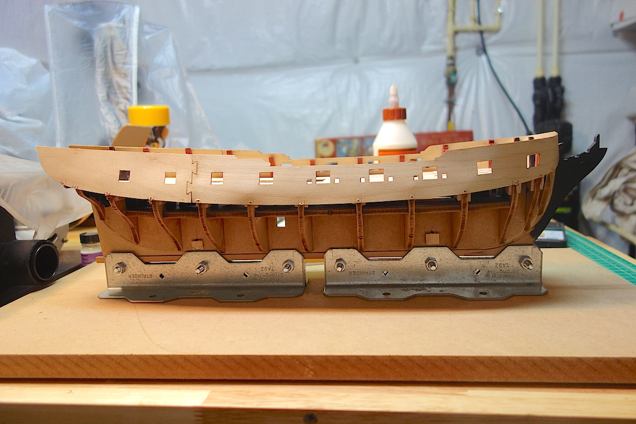
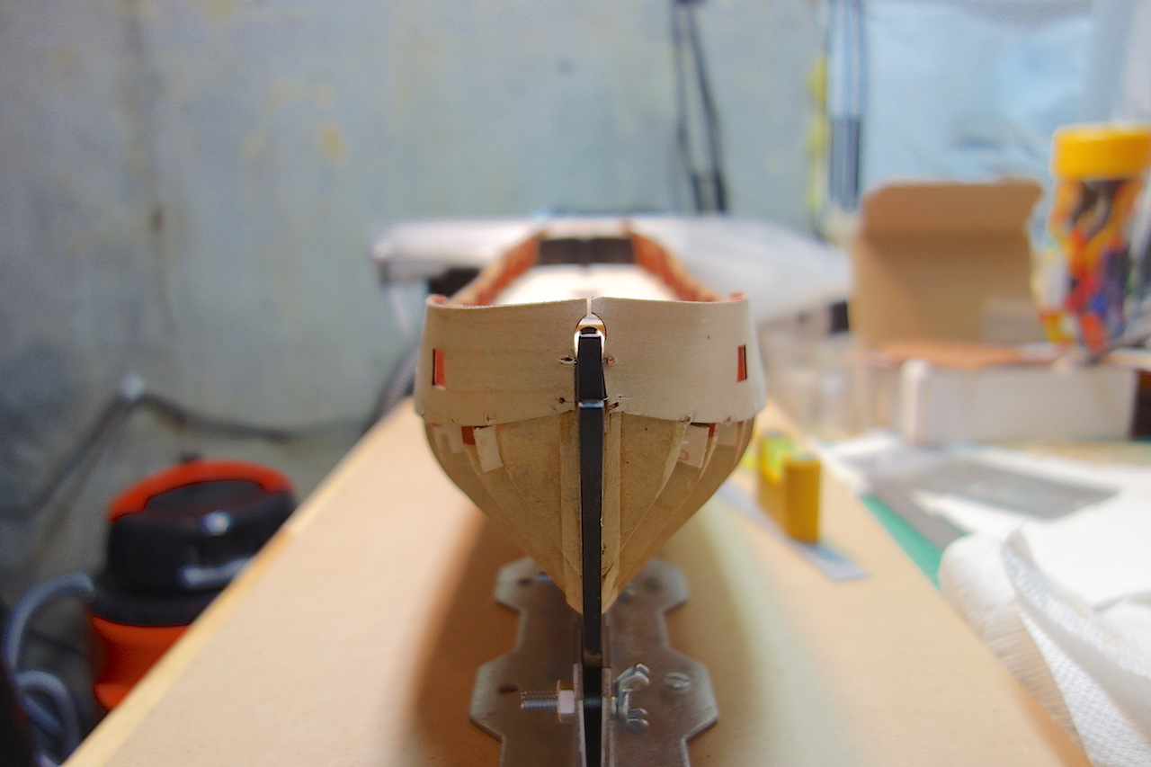
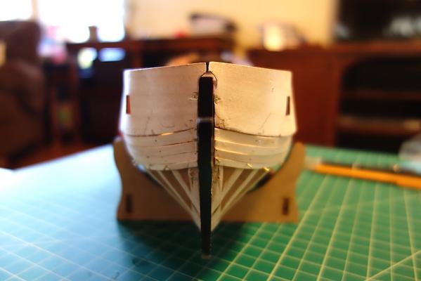
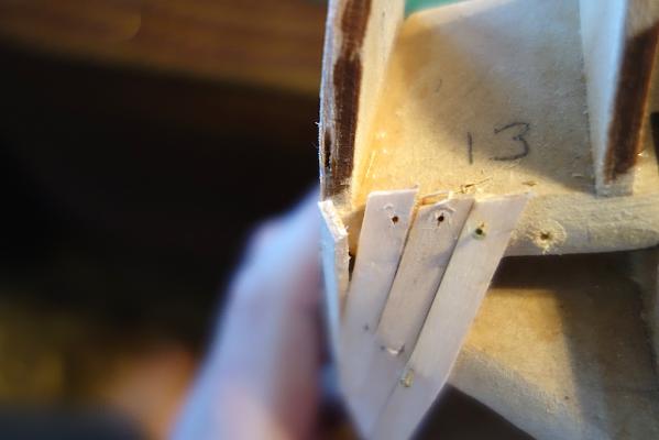
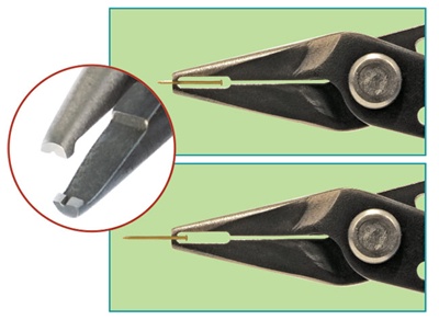
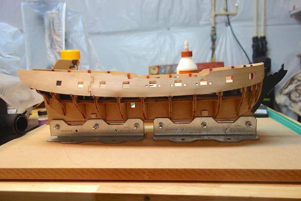
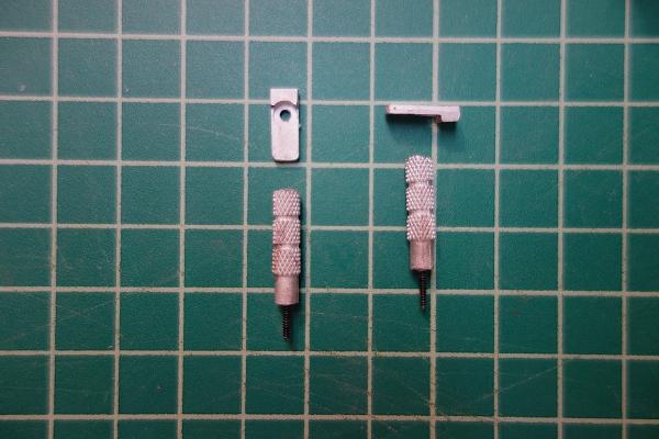
 I started the first planking, and got four rows completed per side. It's going pretty well so far. There are some areas between the gunport pattern and first plank that will need to be fixed with filler and sanding, but overall, the time I spent fairing the bulkheads to get a smooth run seems to have been well worth it. The nice thing about this kit is that the lime planks are 1.5mm thick, giving you plenty of material to work with when it comes to sanding. The lime takes soaking pretty well, and even at this thickness, the planks do bend and twist pretty nicely. The planking at the stern is always the tricky part. The first plank seems to run relatively vertically, and then the next plank starts the horizontal twist up to the stern counter. I don't know that I faired the last bulkhead appropriately, but I figured I would get the planks on and then use filler to get the proper transition between the two planks. I think there is a slight rounded curve to the bottom corners of the stern counter, but once I get the planks on and start fitting the stern counter, I'll have a better idea of what work needs to be done. It's great to get the planks on and see the nice curves of this class of ship come together. The planking screws have been very helpful to get the ends of the planks to sit at the bow and the last bulkhead. Otherwise, I have only been using PVA and two nails at each bulkhead to fix the planks to each bulkhead - I have flashbacks of trying to use CA on my Badger, which was a real pain. I just wanted to share one thing I'm using that has made the pin work very easy. It's the pin insertion plier from Micromark, which is model number 85282. On my Badger, I used the Amati pin pusher (which only lasted that build), but these pliers work much much better. I forget whose log recommended these, but they are fantastic. You have much more control, and you don't need much force to push them through the lime planks and into the MDF bulkheads (no starter hole in the MDF is necessary). A picture of them is below.
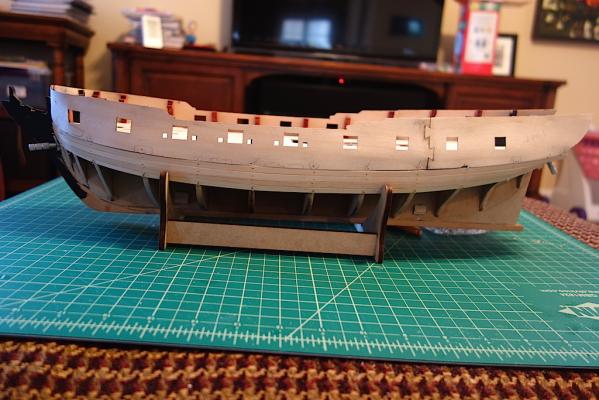


-
I ordered the ensign for my Badger from BECC flags as well. They are cloth, so I think they end up looking a little more realistic.
-
I'm only on my second build, but I kinda agree that in some cases, using the filler blocks seems overkill. As Pete says, two big considerations are the widths between the bulkheads in the more difficult areas, and whether you are planning to double plank or not. I can certainly see at the very front of the bow though that you might need something to attach the planks to. I forget whether I used filler blocks on my Badger build, but for my current Pegasus build, I decided not to. The kit has a fair number of bulkheads, with a good number spaced closely together at the bow. The kit also had inserts that went between the bow bulkheads (and between the first bulkhead and the stem) to help give you something to rest planks on. Since I'm planning to double plank and use filler, I think I can get away with not using them. I also spent many hours fairing the bulkheads, constantly checking and rechecking things as I went along. If you have the bulkheads faired appropriately, it probably lessens the need for filler blocks.
-
Hi John, happy new year! Wow, that's really great work, nice job! Very clean build, and love the improvements. Looking forward to what you decide on the quarterdeck. I'm hoping to get through the first planking on my Pegasus, and will turn back to my Lyme - your pictures are giving me an added push to get that planking done!
-
Thanks SpyGlass, if you happen to have the pictures handy that would be great but don't kill yourself looking for them. If not, I think this gives me enough to go on that I can take a stab at it tonight. The stern is definitely one of those places on the ship that is important to get right!
-
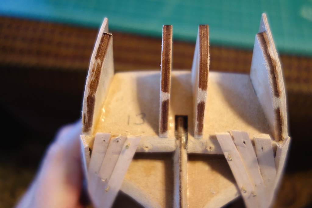
Thanks for looking in SpyGlass. When you say "the last bulkhead needs to very steeply faired, are you referring to bulkhead 13 (on which the stern extensions sit) or bulkhead 12? From my tests, it looks like bulkhead 13 needs a good bit of fairing, especially close to the stern post. At the outer edges, however, it looks like there's sorta a rounded curve as the hull planks move from vertical to horizontal.
-
Hi Martin, thanks for looking in. I probably have at least 8 solid hours of fairing the bulkheads. It's an easy job to do while watching TV at least. I've been using a dust mask, as that MDF dust can be some nasty stuff. To fair them, I've been using these carbide files from Micromark which have worked fairly nicely (I think i'm using the coarse set, and not the fine set): http://www.micromark.com/5-piece-carbide-needle-file-set-coarse-80-grit,7526.html The stern on my Badger was a bit nerve-wracking process, but eventually I just went with it and it turned out ok. The tuck up and into the counter seems to be a lot more acute than I originally thought. I need to play around with the test planks a bit more more, but it seems like I need to fair bulkhead 12 some more, and then put in a pretty decent bevel onto bulkhead 13 so that the planks not only run into the stern counter ok, but also so that there is enough area to fix the planks to it. Right now my planks seem to hit the fore edge of bullhead 13 ok, but I think the planks on the bottom of the bulkhead need to follow the curves of the planking run leading up to it.
-
Looking great Bill. Thanks for the tutorial on making the small boats. I'm thinking of doing the same on all my builds from now on, rather than using the kit resin or cast metal hulls. Results look much nicer!
- 335 replies
-
- 1
-

-
- Constitution
- Mamoli
- (and 3 more)
-
Very nice build Caroline, glad to see you are back. I was following your log during my Badger build to get ideas for my future Pegasus build. It's looking really great.
-
Not much to update. I had to refit the bottom of the gunport patterns in a couple of spots where the pattern separated away from the bulkhead. I used a cut-off wheel in my Dremel to remove any globs of dried glue, then used the planking screws again to get the bottoms in those sections nice and tight to the bulkheads. I'm glad I did so as the work improved the curves in the hull very nicely. I also had to shave back some of the forecastle and quarterdeck deck patterns a bit. The redheart had a bit of flex to it, so I maybe had to shave the patterns back 0.5-1.0mm on each side. Thankfully, keeping the original bulkheads 1 and 12 kept the patterns from pushing the other bulkheads in too much more. I've also been spending time fairing the rest of the bulkheads. This is a process I dreaded, mostly from my Badger build where I only used sandpaper and needle files - so, I only faired the top portion to fit the gunport patterns. I'm using heavier duty files this time, and the work is going a lot easier on this build. Still, the fairing is taking me many hours - thankfully it's an easy task to do while watching football. I used my Dremel a bit for the upper portions, but want to be a little more careful on the rest of the hull to get the curves just right so am working them by hand. A few more to do and then I can start planking. I've decided not to do the bow and stern filler blocks, as there are plenty of bulkheads grouped tightly together in those areas. Plus, in really taking my time in fairing the bulkheads to ensure a smooth run, the test planks are sitting very nicely. I still need to fair bulkhead 13 (the last one where the stern extensions fit), and am trying to figure out the relation between the bulkhead and the stern counter, and where the run of the planks ends. I'm assuming that there is a pretty good bevel that needs to be worked into the bulkhead, and that the stern counter sits against the aft edge of the beveled bulkhead?
-
Thanks BE, hope you and your family had a wonderful holiday and best wishes in 2015! I had a gun setup for my Unicorn build, and used that to test out the gunport heights - I think/hope the gun carriages are roughly the same size. I'll have to cut out the window space on the quarter badges - that's a very good suggestion, thanks guys!
-
A question about Lady Nelson by Amati
Landlubber Mike replied to CharlieZardoz's topic in Wood ship model kits
The Lady Nelson looks like a really nice kit. Even if it does not match a particular ship, as Aldo says, you could always find a cutter you like and modify the kit to build that cutter. I found I got a lot more interested in this hobby when I moved from just building the kit out of the box like when I started my Badger, to researching ships and trying to improve their historical accuracy. Good luck if you decide on this model - and post a build log The Pegasus kit uses MDF as well - I think Amati really does builders a great service in moving the MDF for the keel and bulkheads, as the MDF (at least in my kit) was perfectly flat. I had plywood keel issues with my Corel Unicorn kit, and even had a hard time sourcing perfectly flat 5mm plywood to replace it. Hopefully more kit manufacturers move to MDF. -
Hey Martin, the two shades of red seem quite close. It's too late for this build, but depending on how the redheart ends up looking on the Pegasus, I've been thinking about using it on my Lyme build. Of course that means removing some of the bulkhead extensions (thankfully, there are fewer as Corel just has extensions every 3 or so bulkheads), but maybe I'll stain the more hidden bulkheads to avoid some of the issues I had on the Pegasus. I have a pint of Cranberry stain that from your pictures looks closer to redheart than the Cinnamon and Empire Red stains. I wanted to get in my final wood order to Jeff for my future Charles Morgan build, and so I played around with the General Finishes Whitewash stain last night to see what wood I'll need to replace (there is a lot of white on the Morgan, like the masts, railings, whaleboats, etc). I don't think the GF stains are pure stains - instead, I think they are almost like a hybrid between stain and paint, as they go on thin like stains but do have much better coating power like a paint. I even tried it on some brass left over from my Badger's photo etched sheet - even without priming the brass, it went on very nicely. The Morgan's white masts have rings and other items attached to them that are metal and are also white, so the GF Whitewash will work perfectly. Just thought I'd pass that along in case you are thinking about using white on your build.
- 467 replies
-
- 1
-
-
- fly
- victory models
- (and 1 more)
-
Gorgeous work Bill, congratulations! Nice end of year present Looking forward to your next build!
- 335 replies
-
- 1
-
-
- Constitution
- Mamoli
- (and 3 more)
-
Thank you Shihawk, it's a bit stressful to start gluing and work your way around, all the time checking for accurate alignment. Glad it's done! Those pins I got from Micromark. They might have similar ones at a shop more local to you. I really am glad I had them - they made the work much easier.
-
Aldo, like everyone else, I'm so happy to see you back posting here. It was a lot of fun posting with you as a fellow Badger brother. Glad to hear that you are doing better. Your Triton is looking very nice my friend. Very nice clean work as usual. Hope you decide to stay here and post more regularly, we all enjoy your work and company! Best wishes for a happy holiday and 2015 to you and your family.
-
Thanks Mark. I did think about that, but the problem is that it can then be hard to match the cannon carriages, deck beams and other red items. What I probably should think about doing in the future is dying the bulkheads that won't be seen (which would be mostly the ones at the ends where the curvatures really come into play), and only replacing the ones near the waist (where there are no curvatures generally). Live and learn
-
Thanks very much Aldo. I've put this kit aside for the time being while I learn and get more experience working on the Pegasus. I've sorta gone a bit crazy in thinking that I can not only improve the accuracy of the kit, but also to convert it to its rounded-bow sister. Once I get through the first planking and the stern construction on the Pegasus, I should be able to turn back to this build and rejoin Ian and my other Lyme class brothers.
-
Beautiful work Mark. I love the swiss pear. Hope you and your family had a wonderful holiday
-
Thanks Martin. Do you mean cut a hole in the gunport pattern where the quarterbadges are? I wasn't planning on it, given that I am not outfitting the captain's cabin, but maybe it's a good thing to do to add a little depth behind the windows...hmm... For the planking screws, I found they had a hard time penetrating the plywood patterns for some reason. I poked a hole in them with a push pin, and then screwed them into the MDF. The MDF probably could have used a small starter hole as well. Thankfully none of my planking screws broke.
-
Thanks Spyglass Looking back at my pictures, it appears I was able to get more curves into the pattern than I first thought. The curves at bulkheads 2 and 3 can use a little more work, but that I think I can get from sanding. The patterns are of 1.5mm ply, so that gives some room to play.
-
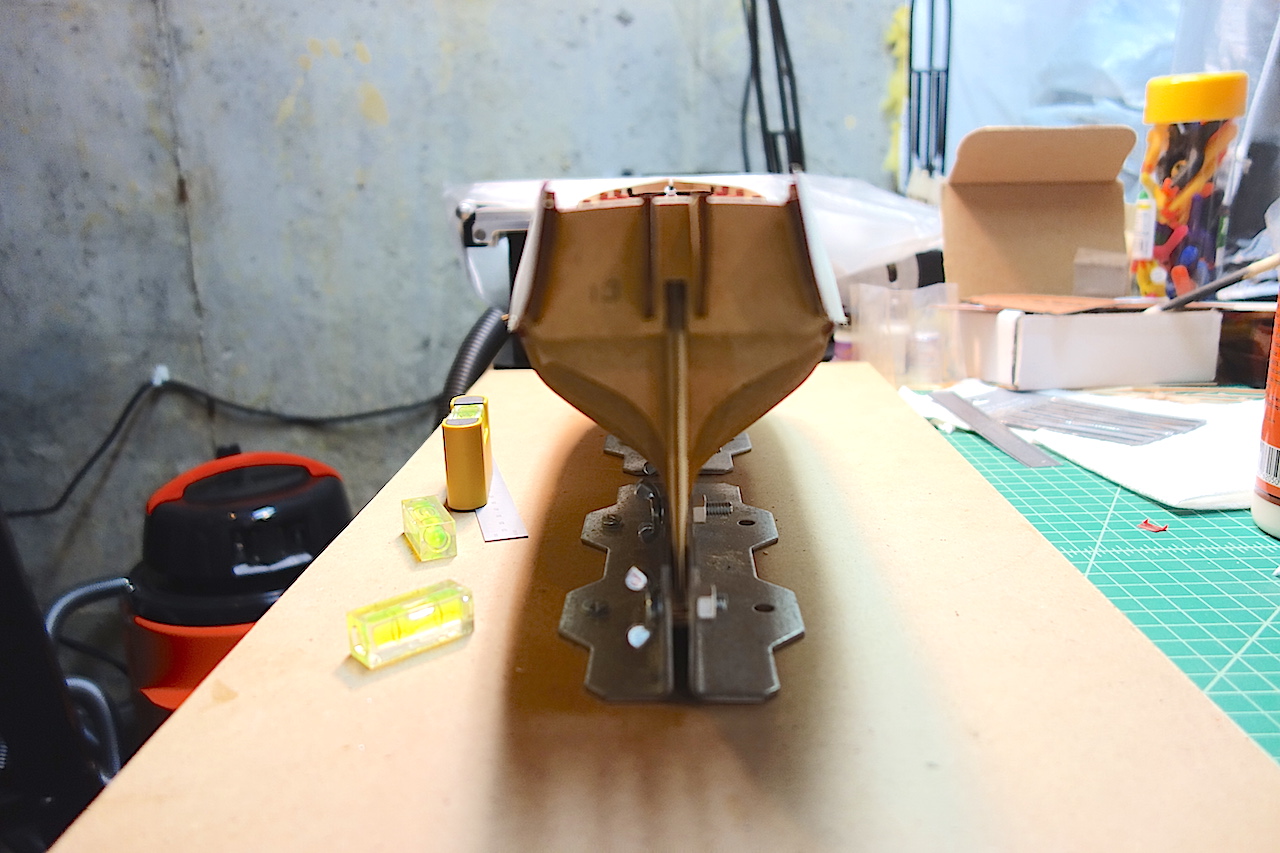
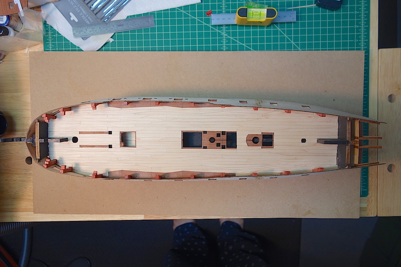
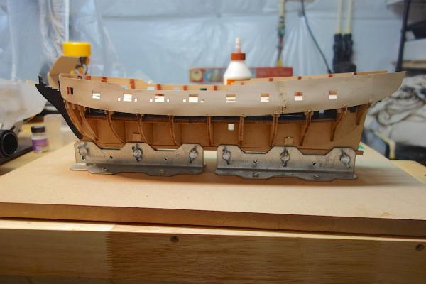
Here are the final pictures. Overall, I'm pretty pleased with how they came out. They are symmetrical and are level with one another, which are the most important factors. I wasn't able to get the patterns to fit the full curves of the first few bulkheads at the stem however. As I feared, the redheart extensions were very fragile. I busted off a few more while fitting gluing the patterns on, so molding the patterns against the extensions was not in the cards. Also, the extensions had a bit of flex to them, causing them to bow in slightly as the patterns were attached. So, the forecastle deck pattern will need to be sanded back a bit to get it to fit. All in all, nothing too major - I think some creative sanding and filling could help me get the hull curves back. Thanks for looking in!


-
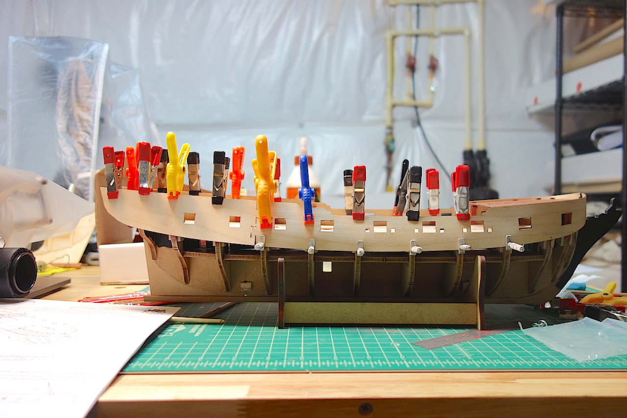
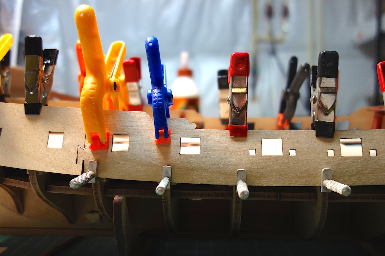
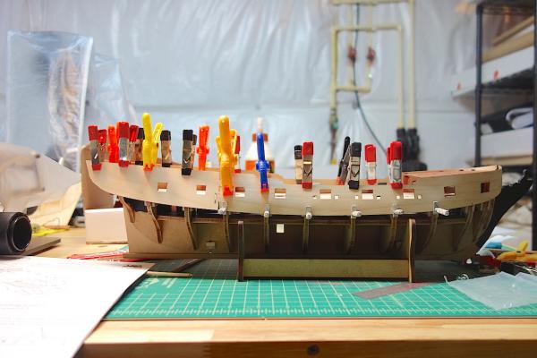
Well, after two nights of frustration, colorful language and adult beverages, the gunport patterns are on! As with my Badger build, fitting the gunport patterns is the most stressful part of the build, and it's good to get this stage behind me. So much of the alignment is keyed to the proper fitting of them, and unlike most items where if you don't like the part, you can remove and replace it, the gunport patterns are pretty much there to stay. I know that kit manufacturers use the patterns to make things easier overall, but it really would be helpful if they provided a little more instructions and guidelines to help people along. The Caldercraft Badger instructions were fairly good, but the Pegasus instructions really only said to fit the patterns against the tops of the bulkheads. They should tell you how much extra material is built into the bulkheads, how to fit them at the stem, how to fit them at the stern extensions, etc. The plans also incorrectly show the jigsaw connection sitting on bulkhead 9 - from my fitting and other logs on here, the connection is just aft of that bulkhead. In addition, I found that the bowsprit hole in the patterns is pretty worthless - you can see in my next post how much I had to sand back the fore edge of the pattern. The first soaking and fitting got the patterns in a very good shape aside from the bottom (I didn't pin the bottoms of the patterns, so they lacked that gentle curve against the middle of the hull). When I soaked them for the second time however, the patterns relaxed a bit and straightened out a bit. So, while I had planned on soaking and fitting them three times, I ended up just doing it twice. Here are some pictures when I started with the starboard side. My approach was to get the two halves pinned and clamped, then start with the end of the front pattern and work my way forward. Then I worked the back pattern starting from the jigsaw connection to the stern. When I got to the stem, I slowly sanded the fore edge back until it fit snug against the stem. I don't think you can fit the patterns starting at the stem and working towards the stern - aligning the patterns at the middle was a much better approach I think. I bought these planking pins from Micromark for my Badger, but never used them. I found them absolutely indispensable for attaching the bottom of the patterns on the Pegasus. They really helped ensure that the patterns fit tightly against the bulkheads, and for the ends of the patterns against the stem. They have a very strong screw with tight threads, so once you get it into the bulkheads, they worked like a charm. They are knurled though, so they are pretty rough on your fingers when trying to get them started into the MDF. I'll post the final pictures in the next post.

-
Thanks very much guys. Hope you and your families had a nice holiday. Jason - I would think that most of the details will be covered up as I am thinking of having a very busy deck showing a working ship in sails (probably a mixture of full of furled). But, it was fun to try out and improve my skills a bit. Spyglass - I did adjust the clamps a bit to help get the curves in. I'll detail a little more in my next post, but it was a bit tricky with the redheart extensions. Martin - first try, but hours of finagling, running back and forth to the plans and your log and others, etc. The pictures above don't show all the blood, sweat and tears that went into fitting them (well, no blood this time). Aldo - thanks very much. Hope you are doing well my friend. I hope you don't mind, but I copied some pictures off your log showing your main bitts construction. They will be very helpful resources, thank you!
-
Wow, looking really great Joe. Very crisp details, and your deck is fantastic.