


Landlubber Mike
-
Posts
4,541 -
Joined
-
Last visited
Content Type
Profiles
Forums
Gallery
Events
Everything posted by Landlubber Mike
-
 Hi everyone, I'm in the process of working on the wales for my Pegasus, and plan on adding two rows of top and butt planking. Earlier for my deck, I added top and butt planks, but those were hand-cut as the maple I was using was only 0.5mm thick. I'm using 2mm pear for the wales. I was thinking about using the taper jig on the Byrnes table saw to cut identical planks. Since I'd like to keep all my digits, I was wondering if anyone had any tips for using the taper jig. Specifically, how does one set up the hold downs for the plank? The planks are only going to be about 6mm wide and maybe 135mm long, which doesn't leave much clearance from the saw blade. Also, is it worth considering stacking up a bunch of planks and running them through the saw at once? If so, how do you hold them all down? Do you glue them together, cut the two tapers, then use isopropyl alcohol to separate them? Or is it just better to cut each plank individually? Thanks very much in advance!
 -
Beautiful work Mark. Wow, this lady sure has a lot of curves! I can see how all the spilling, etc. takes plenty of time.
-
Hi Jason, good idea to start planning all this in advance. I throw these thoughts out there with the caveat that I only have one build under my belt, and my Badger had much simpler rigging given its size and only two masts. Like Joe, I would strongly recommend leaving the spiritsail for as late in the build as possible. I can't tell you how many times I clipped it, which popped off rigging on the bowsprit and even the fore mast. I felt like I was spending literally 30% of my time redoing my previous work to fix all these accidents. In terms of the masts, I went fore to aft. Given my problems with the bowsprit, I'm going to think about whether it makes sense to start from the stern and work my way forward - even leaving the bowsprit off for as long as possible. Someone else had suggested that to me, and I think that person said that zu Mondfeld suggested that approach. I don't know if that included doing both the standing and running rigging together (i.e., start with the mizzen and run all the rigging, then move to the main mast and do all the rigging, etc.), but obviously you're past that decision point now. A few more suggestions. When it comes to belaying points, it might be helpful to fix lines starting at the center of the model and work your way outwards. Also, if possible, consider not fixing the standing backstays until towards the end of the rigging. I don't know how I would have gotten to the center belaying points if the standing backstays were fixed earlier on (the Badger instructions called for installing all the standing rigging, then do all the running rigging). Along those lines, if you are going to add small boats, I went ahead and installed them before starting much of the rigging. The Badger instructions called for them to be installed as the very last item on the build, but I have no clue how anyone could add them once all the rigging was on. I'm sure you'll do great whatever you decide. Just watch the elbows!
- 800 replies
-
- 4
-

-
- snake
- caldercraft
- (and 1 more)
-
Workshop Set Up Question
Landlubber Mike replied to ChrisLBren's topic in Modeling tools and Workshop Equipment
Hey Chris, congrats on the move, new place, and of course the growing family I set up my workshop in my basement. It's in the unfinished room where my HVAC and water heater are. No windows, about 20% is above grade, and concrete floors. I use two Harbor Freight workbenches placed back to back for a workbench "island," and have a Fein shop vac. I have the Byrnes suite of tools, a sherline mill and lathe and a Dewalt scroll saw that sits on a stand separately. I had a lot of similar concerns on dust collection, lighting, the proximity to the HVAC unit, etc. Since I'm not ripping big boards or anything, and my modeling is very slow, I'm not really making all that much sawdust and got comfortable putting the workshop in that room. I use the shop vac regularly, and hung one of those dust filtration devices similar to the one you linked to from the joists in the ceiling. Mine is a Rikon from Woodcraft which I got when it went on a good sale. The nice thing about the Rikon is that you can set it to run on a timer, so that it continues to run for an hour or longer after I leave the room. If I was doing any heavier work, I likely would have found a different place to put my workshop given that the room is enclosed and contains the HVAC unit (even though the air intake to the HVAC is from outside the room). That being said, I don't spend all my time on my builds in that room. I usually spend most of my time working on the model or various assemblies for it in my living room. Other than that, I added overhead fluorescent lighting over the workbenches and a few of those cushy standing mats around the workbenches (they actually make a big difference to your comfort if you are standing!). I am envious of people with nicer workshops with TVs, windows and finished walls and the like (though, working with power tools, it's probably better for me at this stage to not have any distractions). Until my kids move out, which won't be for a couple of decades, that's not really an option for me at this moment. Maybe if I didn't have twins the second time around, but not much I can do now Let us know what you decide! -
Hi Mike, great start on your Unicorn. Ian and John have great build logs on here with a lot of information. I started the Unicorn, which I decided to convert to her sister ship, the Lyme. I'm taking a break from it while I get a little more experience on the Pegasus (especially since I plan on scratching a lot of the Lyme), but will turn back to it in the near future. In any event, welcome to the club I agree on moving the figurehead. It's a bit tricky using the kit piece as it's fairly narrow, and I think more narrow than the stem in some areas. I still think it can be done though. Take a look at my log for where I originally thought I would install the figurehead (now I'm planning on using a lion as the figurehead which is what the Lyme used).
- 51 replies
-
- 1
-
-
- first build
- corel
- (and 1 more)
-
Subscribed. This is going to be awesome. I have the CWM on my shelf and will be following your log. No pressure
-
Great work so far Charlie. Keep taking your time on getting the lines right - all this work will pay off in dividends in the end.
-
That is really amazing work. I love the furled sails and how you imparted the look of age to the wood with the finish. One day hopefully I can approach turning out models half as nice as yours.
-
Wow Brian, looks fantastic! Interesting about your thoughts on stropping the blocks with wire versus thread. I had a devil of a time using rope on my Badger's 2mm blocks, and was thinking about trying wire.
- 831 replies
-
- 2
-
-
- Armed Virginia Sloop
- Model Shipways
- (and 1 more)
-
Gorgeous ship and gorgeous build. Very nice work!
-
The pencil looks great Martin. I think I can get away with not using pencil as I plan on staining the area from the wales down in black, and the wales to the friezes in a darker brown. If anything, the brown stain should settle a bit between planks to have a slightly darker look from the planks themselves. Penciling the boxwood planks works very nicely. I don't know how I feel about treenails though. I've seen them done to great effect by the very skilled modelers on here where the planking and general construction was very clean. At my skill level, I worry like you that they will just serve to highlight issues with my planking. I'm going to copper my Pegasus, as I've never coppered a hull before and would to try it out at least once. I'm also planning to spile my planks as a practice run for when I ultimately turn back to my Lyme build (which won't be coppered). The copper will hide any errors Interestingly, I noted that many people add a thin black strip over the top of the copper at the waterline for a clean look. Part of the reason I'm going with black planks down to the water line is so that the whole effect is clean to the waterline. Probably easier said than done like most things in this hobby
- 467 replies
-
- 1
-
-
- fly
- victory models
- (and 1 more)
-
First time rigging - being organized
Landlubber Mike replied to RichardG's topic in Masting, rigging and sails
Sounds like you guys are very well prepared on the rigging. I've only done one ship so far, but one thing I would suggest (echoing the others) is taking a little time to understand the various lines, and then planning out your strategy on the order in which you will tackle the lines. There are all kinds of strategies, and sometimes, I think there are better approaches than those suggested by the kit instructions. Here are some thoughts from my experience that I can share: 1. On my Badger, I did all the standing rigging first, then the running rigging, mostly starting from the bowsprit and working my way aft. I can't tell you how many times I bumped the bowsprit, which caused me to have to go back and repair those lines. So, I think on my next build I will try to work from the stern to the bow. 2. Another suggestion is to figure out which lines will be belayed to the center of the model, and work from the center outwards. It really gets hard to get to the center as you start adding lines to the ship. In particular, I remember adding lines like the backstays much later than the kit instructions suggested. Frankly, I have no idea how I would have belayed some of the lines if they were on. 3. Make sure that your blocks are securely stropped and that you watch the tension on your lines. I had some issues where as I put tension on the line, the stropping came off my blocks. Stropping your blocks the right way from the beginning helps a lot to avoid this issue. Also, as you start adding tension to a line, it could result in adding too much tension to other lines leading to things popping off. I don't know the best way to avoid this. I secured my lines as I went along (and in pairs to the extent you had a particular set of rigging that went both starboard and port), but I know some people run all their lines and then secure most or all of them at the end. Rigging can be very frustrating at times, but overall I thought it was a fun part of the build. So, try to have fun! -
Looks great to me Martin, very nice job! Did you use pencil in between the planks? Are you planning on adding treenails on the hull? I've lined the hull for my wales and the rails, but need to take the next step of starting to plank the hull. Seeing how nicely your hull came out is giving me the inspiration to start tackling that. Plus, I'll be coppering and staining, so I can cover up what are sure to be a number of mistakes
- 467 replies
-
- 1
-
-
- fly
- victory models
- (and 1 more)
-
Great choice Joe. I have the kit, and had a hard time deciding between it and the Pegasus. I took a bunch of pictures last fall of the ship when I was in CT - John posted a bunch of them on his blog. Happy to send you any if you would like to see them.
-
Gorgeous build Joe, thanks very much for sharing with us. I really liked the "Aged White" you used for the white stuff. Congratulations! I like others are wondering what your next build will be...
- 302 replies
-
- 2
-
-
- granado
- caldercraft
- (and 1 more)
-
Landlubber Mike's technique for furled sails
Landlubber Mike replied to Landlubber Mike's topic in Masting, rigging and sails
Wow, thanks for the info! I used Swan IV to help me with the sail sizes, rigging, etc. for my Badger, but the sail construction update would have been nice to have as well. Since I'm going to add full sails to my Pegasus, this supplement seems to be a great resource. -
Frank, I just went to your bird carving website and was blown away. The green heron is absolutely incredible as is the rest of your work. I've been thinking about getting into small carvings for my ship models (figureheads, etc.). I have a Dremel, but was thinking about something for more detail work. Those Gesswein tools seem very interesting...thank you for the recommendation. I went on eBay to see if any were for sale, but it looks like there are lots of knockoffs of that tool being sold from China. I would definitely stick with the real deal.
-
Landlubber Mike's technique for furled sails
Landlubber Mike replied to Landlubber Mike's topic in Masting, rigging and sails
If you're furling the sails, it's not as imperative to use very thin sail cloth. If your cloth is thicker, you just have to use less material. That's the beauty of adding furled sails. Hopefully I'm not mixing up my lines and blocks, but looking at my Badger, for some sails, I added clew blocks (or a tackle of blocks) to the end of the dog eared part of the furled sail, and others, the line was started at the clews - essentially, I think it depends on the sail. Here was an "a-ha" moment for me about clew blocks in trying to translate the kit's plans which didn't like most kits, didn't call for sails but had clew blocks just kinda hanging out there on their own: http://modelshipworld.com/index.php/topic/604-brig-badger-by-landlubber-mike-caldercraft-164/?p=116375 -
Landlubber Mike's technique for furled sails
Landlubber Mike replied to Landlubber Mike's topic in Masting, rigging and sails
Hi Randy, I haven't thought about sails since I finished my Badger. I'm probably going to add a mix of full and furled sails on my current Pegasus and Lyme builds though. I would say try to find the thinnest high quality cloth you can for better scale, workability, etc. I'd also consider making the sails a tad bulkier, but I've heard conflicting views. Some like zu Mondfeld say that furled sail should be about the size of the yard. Others say the furled sail should be bigger. Artist's choice would be my response As for lines, I didn't include bowlines or reef points. I'm fairly certain that I added all the blocks - with the caveat that given that the Badger was a brig and a therefore a smaller vessel, I often went with simpler tackles using single blocks, as opposed to tackle arrangements with double blocks. One more thing to consider is that the Golden Hind was from the 16th century. I'm not sure how much, if at all, rigging differed from rigging used in later periods. Beautiful build by the way - looks gorgeous and I bet would look nice in sails, furled or otherwise. Hope that helps. Good luck with your build! -
Great looking build Vince. Good luck on the transom, but given how nice the rest of the build is going, I have a feeling you won't need it
- 593 replies
-
- 2
-
-
- royal william
- euromodels
- (and 1 more)
-
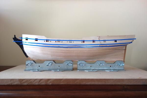
Here's a quick update. I marked the waterline, and have been marking the hull for the location of the wales, as well as one of the rails. This has literally been hours of work for me! I don't know if it takes others this long, but I really want to make sure that I get the wales right for not only a smooth line, but also because accuracy is key as the rails, planking, stem and stern items, etc. will flow from how the wale is placed. I used 3mm blue tape. The bottom two tape runs mark the upper and lower boundary of the wales. The upper tape marks the top end of the waist rail (the waist rail will be 2mm in width, so the tape is a bit wider). Placement of the wales is tricky. I had to look at logs from BE and others to see how it should end up at the stem and stern. The wales are 12mm wide - I plan on using 4mm straight planks for the top part of the wale, and top and butt planking for the bottom two rows of wale planking. As you approach the stem, as noted in TFFM, there is a slight reversal of the sheer curve of the wale where it flattens out a bit. At the stem, there is sort of a tuck in under to the stern counter by the lower piece. So you essentially go from having a rather flat wale for most of the ship to more of a curved portion at the stern. Martin's Fly log shows how he carved a custom piece of planking for the aft-most, bottom-most plank of the wale to very good effect. Thanks to everyone for their thoughts on how to plank the wale. I think I'm going to attempt planking it as one layer. It just seems easier, but If I run into trouble, I can switch over to a laminate approach like Chris mentioned. I'll mark the boundaries in pencil, then add a temporary batten along that pencil line to help me run the wales in a smooth line. I plan on staining/dying the wales and the planking (both in pear) down to the copper line in black. Things will get tricky from there. Above the wales, I plan on planking the area just under the waist rail in pear, and stain it a darker brown. The area just above it is the area with the friezes. Again, to avoid paint, I plan on staining the planking there using blue stain. I got a nice dark blue color on pear, while it was too "french blue" on maple. I might test the stain on boxwood to see if I can get more of an in between color. The waist rail will cover up any seams, etc. between the two stained areas. I haven't decided whether to go with separate planking runs for the two areas, or run the planking, stain the areas as mentioned, and hope the waist rail covers up any stain runs. To be safe, I'll probably go with the former. After the two frieze areas, there is another decorative rail that I will plank in redheart. It seems like a number of the Swan class ships used red in this area, and I think it should tie in nicely with the redheart I'm using in the rest of the build. This is quite ambitious and a lot more complicated than what I had to do on my Badger, but I think I have a game plan. Now I just need to execute
-
That looks like a really nice kit. Really nice job Chris and Amati!
-
Hi everyone, I've been stuck on a big project at work that finally wrapped up last week, so finally have some time to get back to the shipyard. Executing the different stained areas is going to be a bit tricky, so I've started by lining off the hull with respect to the wales and some of the sheer rails. At the suggestion of some on here, I also picked up the Jim Roberts pamphlet "Planking the Built-Up Ship Model" from Model Expo which was on sale for $2.65 or somewhere around there. It's a nice pamphlet on the topic and so I wanted to thank people for the recommendation. The pamphlet says to start with the wales, and the run the planking above and below it using the planking bands. This seems like a very good approach to me. Question: Should I do the wales using thicker planks so that I'm just using one run of planks for the wales on top of the first planking layer? The kit (and other kits) generally have you do all the second planking, then add another layer for the wales. It seems like it might just be better to use 2mm thick planks, which would give me a cleaner line around the stern counter (but would require a slight modification to the rabbet at the stem). It would be a little harder using thicker planks, but I'll be using swiss pear so I'm not anticipating too much difficulty. Any suggestions or tips on which approach is better and why? Thanks very much in advance!
