clearway
-
Posts
2,218 -
Joined
-
Last visited
Content Type
Profiles
Forums
Gallery
Events
Everything posted by clearway
-
 Maybe give it a blue wash like the german sub to blend the colour differences together- but definitely looks like it has seen some work. Keith
- 65 replies
-
- 2
-

-
- X Craft
- I Love Kit
- (and 2 more)
-
Looking good Alan- the differences in colour on the eduard etch is left over from the acid where they "half etched" some parts to make them thinner - see this on a lot of their 1/35 armour upgrades. Keith
- 65 replies
-
- 1
-
-
- X Craft
- I Love Kit
- (and 2 more)
-
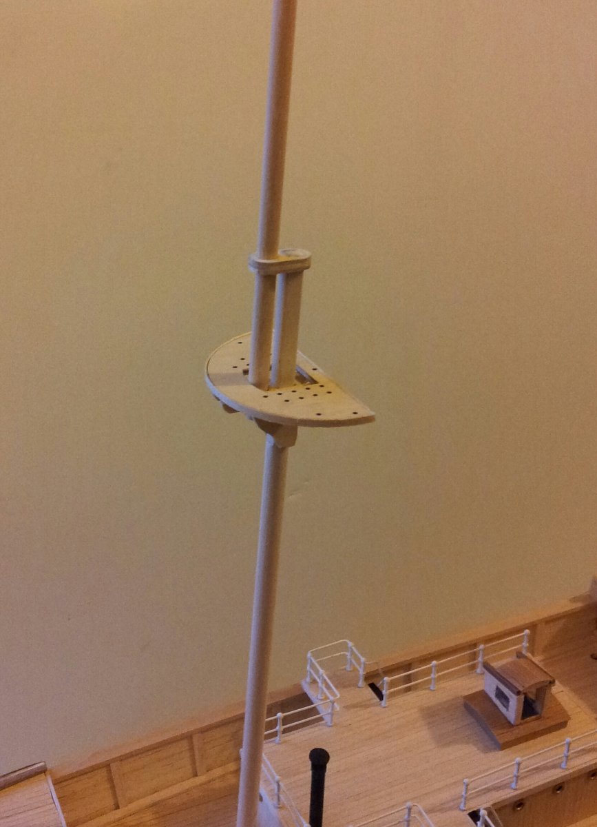
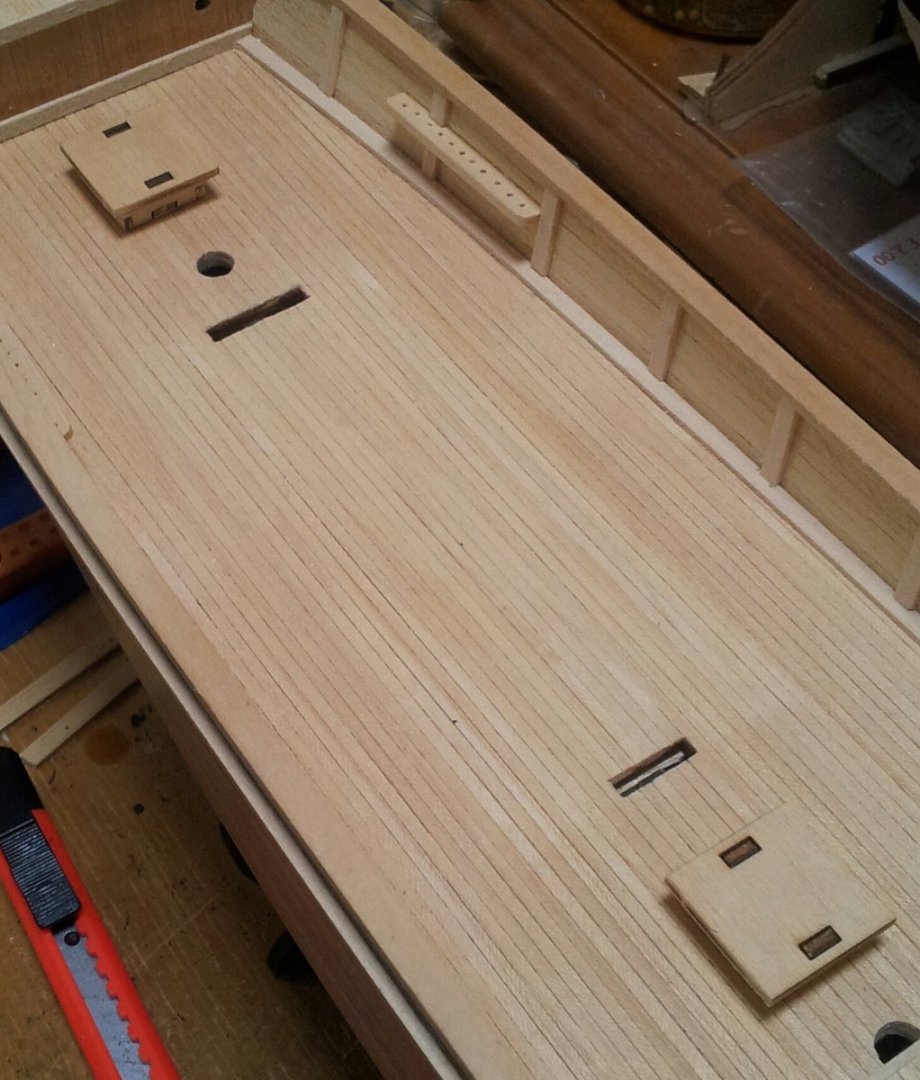
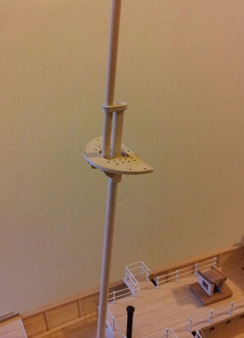
thanks for looking in- back with Endurance and the pinrails for the foremast are fastened onto the bulwarks, also started on the well deck mounted skylights. The topmasts have also been tapered- first the usual gradual taper- then for the last 20mm or so tapered at a more acute angle then the mast cap added (used photos from the book "south with endurance" for reference). Take care all Keith
-
Ahh i wondered what you were up to these days Obvious- i would double plank the hull but use 4 or 5mm wide planking strips like on my Terror build. Out of interest the part of England (originally Scotland till the 1100's) i live in was largely settled by the Norseman and we still talk a la'al birra ancient norse, "as fra Cumbria- oos it gaan" 😁 and all the place names are viking in origin- we still call our hills Fells and the mountains pikes (Englands highest mountain which is about 30-40 km from where i live is now called Scafel Pike but locally in West Cumbria we still pronounce it the old viking way which in english would be spelt Scawfell. you can see why the Norwegians liked our locality! Keith
-
all i can say is your experiment was a big success! I know the feeling though- sometimes it's the dread of the project that stalls you, and when you actually start it all falls into place. Keith
-
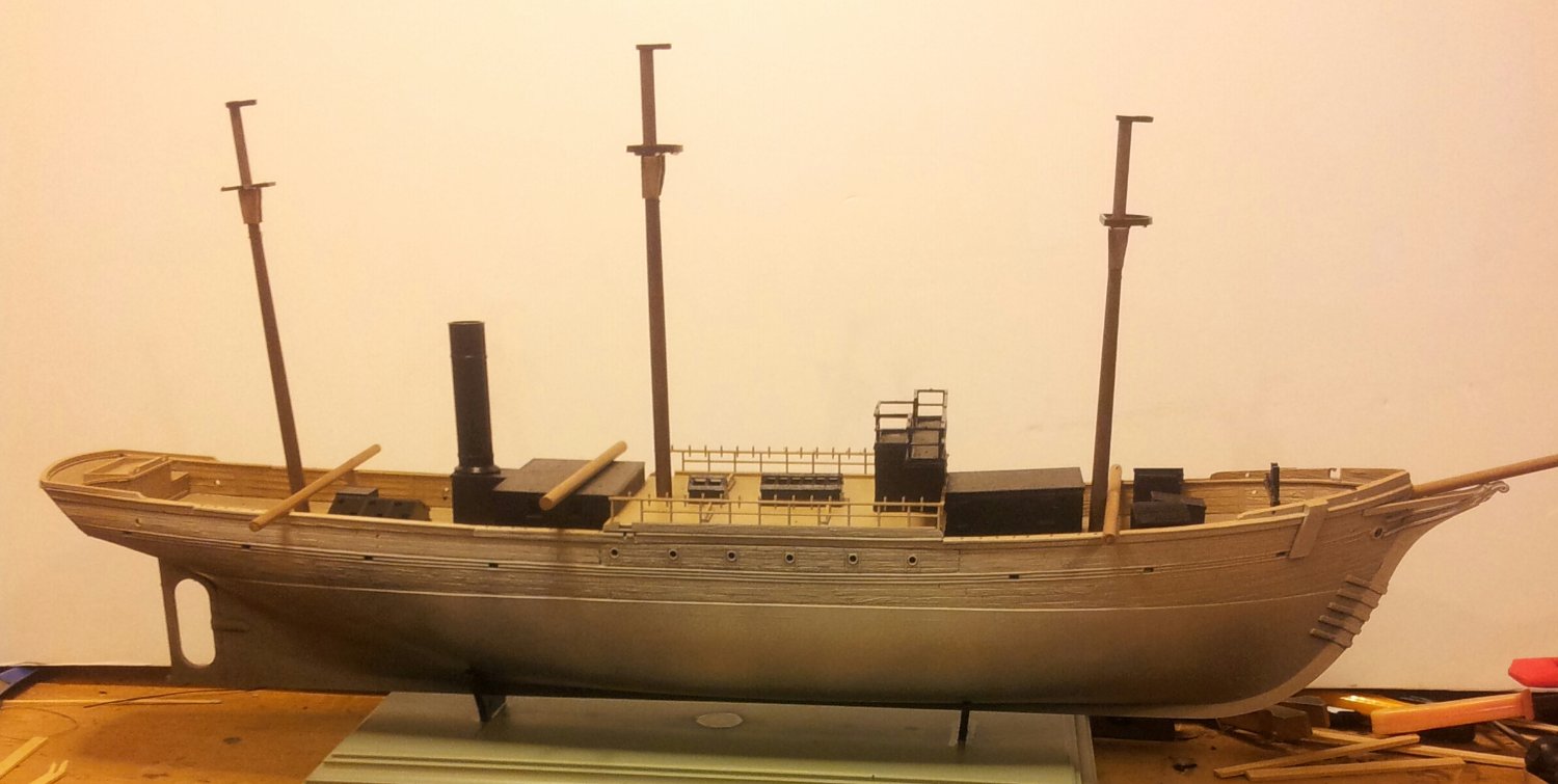
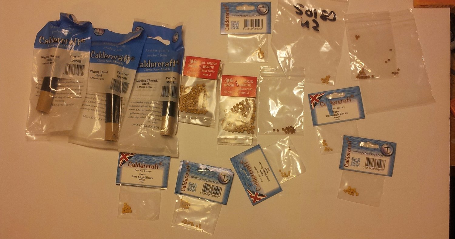
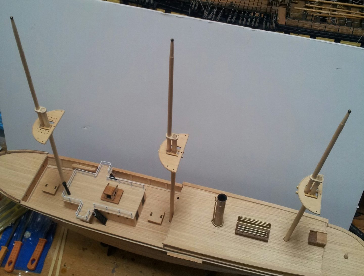
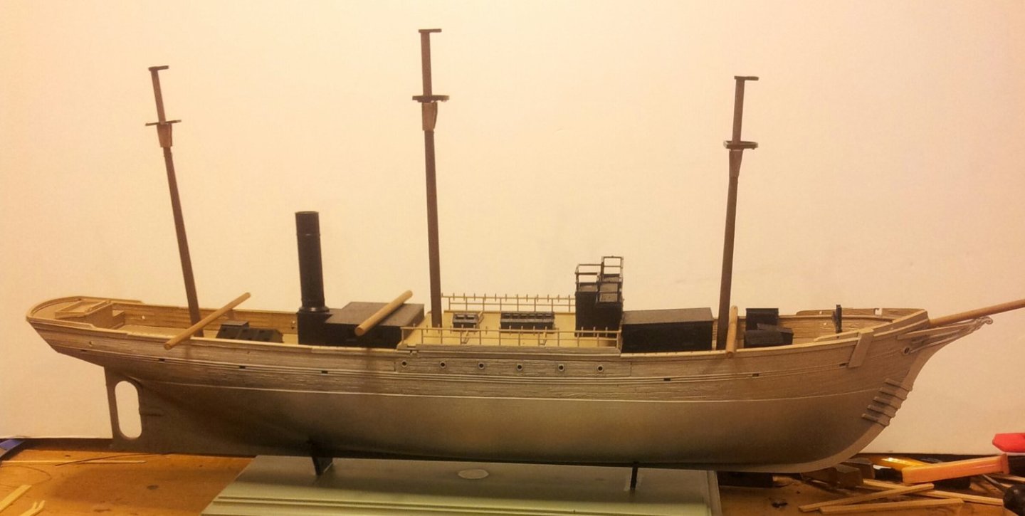
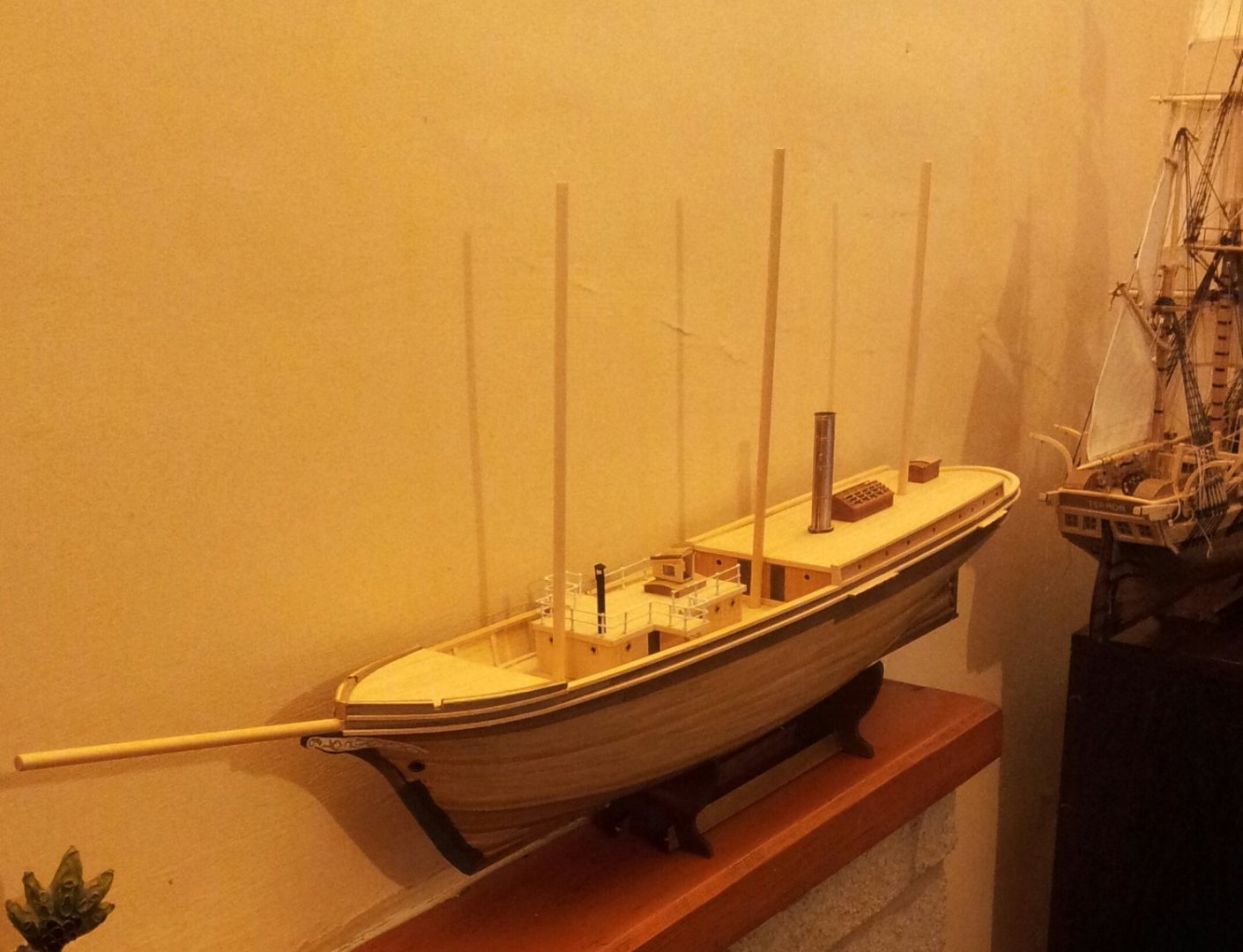
Thanks for looking in- little bit of progress in the yard with the hull given a misting of humbrol white primer to help see some of the detail and the deck primed and given a coat of tamiya deck tan (will use some AK interactive filter for light wood before varnishing). Also the plastic mast caps have been added to the lower masts - the tops arnt glued yet to allow some "tuning"- used superglue gel for these. the dowelling resting on the bulwarks is the topmasts which need tapered. Also a pack of the extra goodies i ordered from cornwall model boats😁-OMG the 2mm deadeyes are so smalllllllllllllll😬. Take care all Keith

- 22 replies
-
- 7
-
-
- Pourquois Pas
- Heller
- (and 1 more)
-
Thanks Greg- Yep the heller kit has the belaying pins on the midship railings but that is it, the idea of cleats for the braces makes sense so will go with that😁.. and nice yacht - and nice to see accurate looking kit provided sails. Keith
-
that wood is going to look really awesome when varnished Greg- quick question as your plans/ instructions will be more concise- on the heller model there are no belaying pins on the bulwarks for the fore and mizzen mast, i know from photos that there were pin racks on the shrouds but not sure if on the bulwarks and did they fasten the braces to cleats? Keith
-
i use two pieces of "u" shaped brass wire glued into a piece of wood bent to the distance apart i want the deadeyes to be, then rig the shroud to the upper deadeye with the "spacer" attached to the shroud deadeye and channel deadeye- once the shroud is secured to the deadeye release and move along to next- i normally do the shrouds in pairs starboard to port (Hope all that makes sense). Keith
-
i am doing hellers 1/100 pourquoi pas and will be using 2mm and 3mm deadeyes so i can appreciate your pain there Phil- oh god they are small but at least mine doesnt have as many shrouds as yours! Keith
-
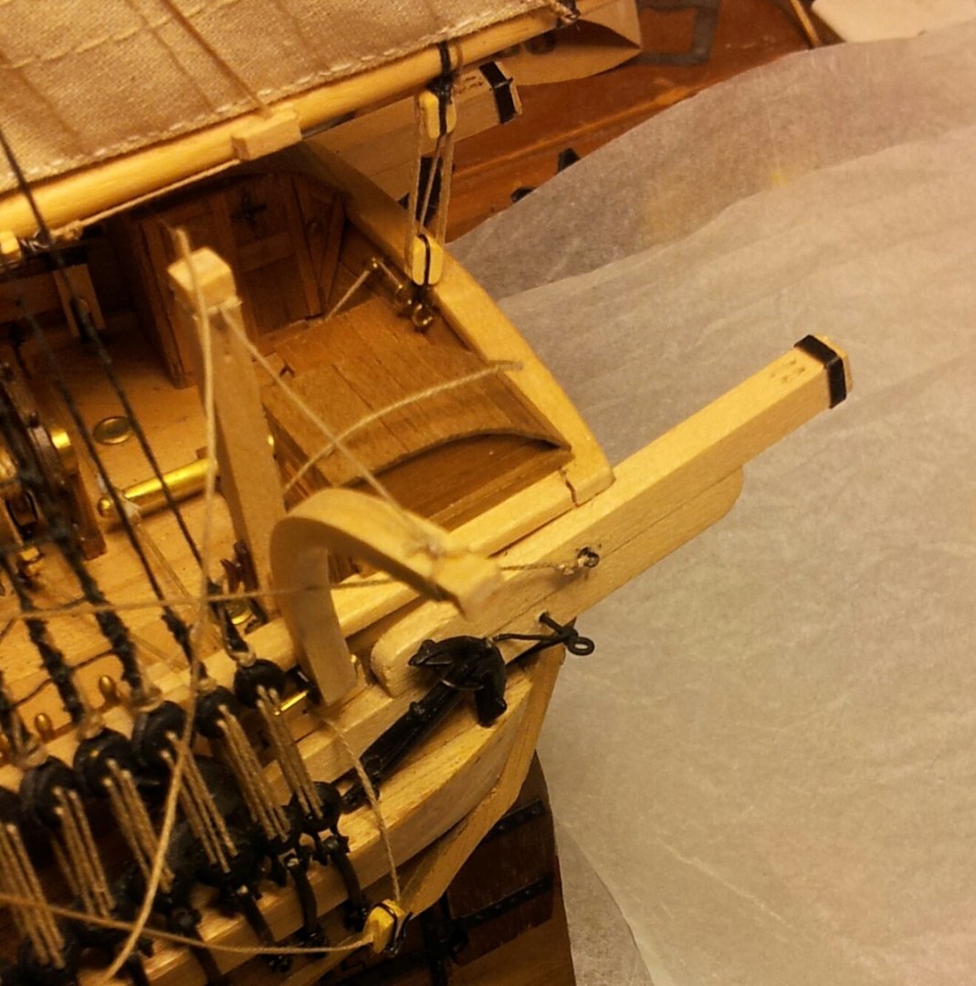
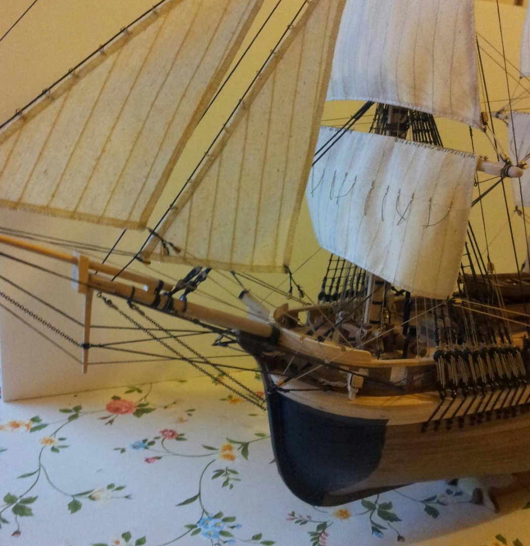
Thanks for the likes and comments and looking in everyone- this evening after a couple of days of pondering i unhooked the long suffering rigged/ unrigged main brace and made an outrigger from one of the brass eyes from the kit fittings with a piece of soft brass wire from my spares pile wrapped around it near the eye to form the two diagonal supports (one leading forward the other downwards. will need a coat of varnish and then hopefully i can finally get the brace rigged! Take care all. Keith
-
You should be o.k. using Biddlecombe as a reference Hake as i used rigging details from Lees from the mid 1800's . In the plans for Terror you can see the "arm" and supports in the side elevation, but nothing on the plan (top) view! Keith
-
Thanks for looking in everyone- bit more progress with railings added to deckhouses and masts tapered - will most likely use the tops supplied with the kit as they look good. Take care all Keith

- 22 replies
-
- 4
-
-
- Pourquois Pas
- Heller
- (and 1 more)
-
Thanks for looking in everyone. work continues with the rudder pintles and masts and the ritz ladders painted and glued in place. Take care Keith
-
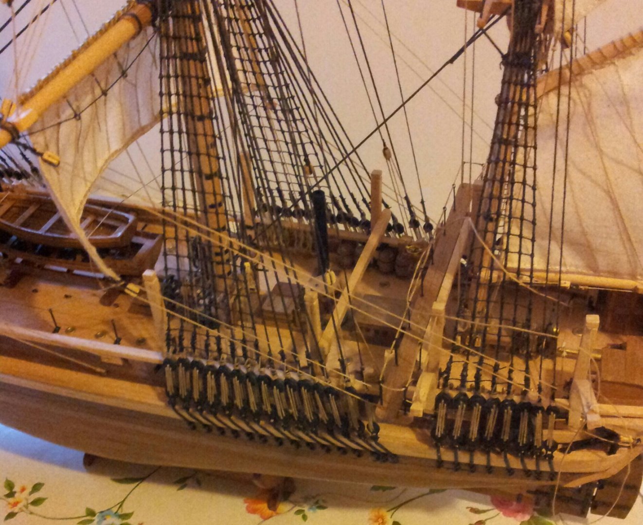
Thanks for looking in and the likes- always appreciated. Weather is very very how shall we say bonkers at the moment with beautiful warm sunny days followed by wind and rain - sometimes during the same day! With Terror the point of no return regards the bridge and azimuth compass post which are now glued into position. Also the main braces are now belayed but still need the tails coiled- i suspect there might actually be an outrigger at the stern for the block which guides the brace to the sheeves in the bulwark to clear the anchor there, but can't find enough details. At the bow i now have the stay sail sheet rigged though like the jib sail still needs the tack rigged. Take care all Keith
-
Looking good so far Daniel- let the fun begin! When rigging mine i didn't do the buntlines though didn't have a great many belaying pins left over spare so suspect the buntlines would have shared a belaying pin for same part of sail if that makes sense. Also great to hear you escaped the wildfire- must have been hairy! Keith
-
Worth the extra work going for the more detailed option......hmmm what was i saying the other day about sanity and ship modellers😁 Keith
-
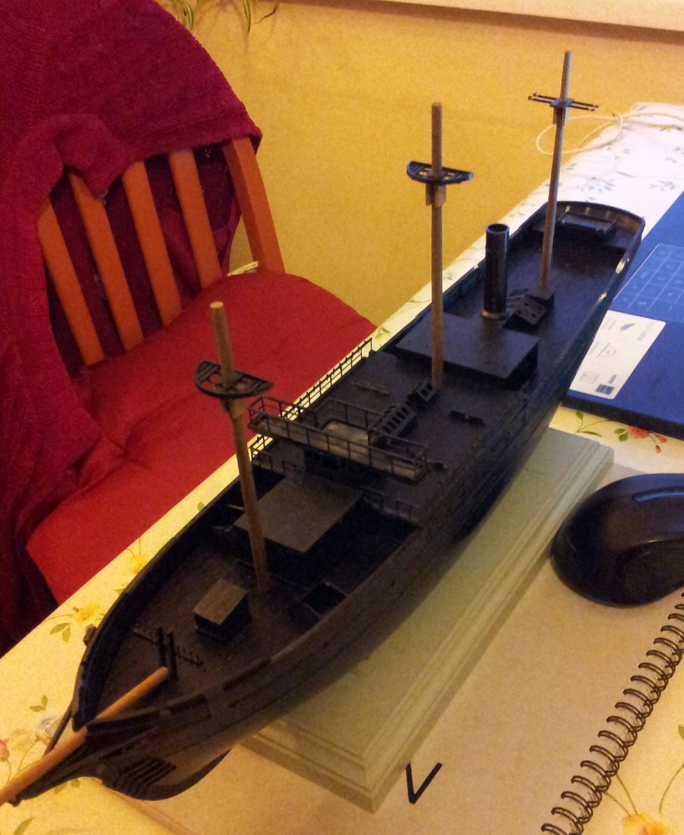
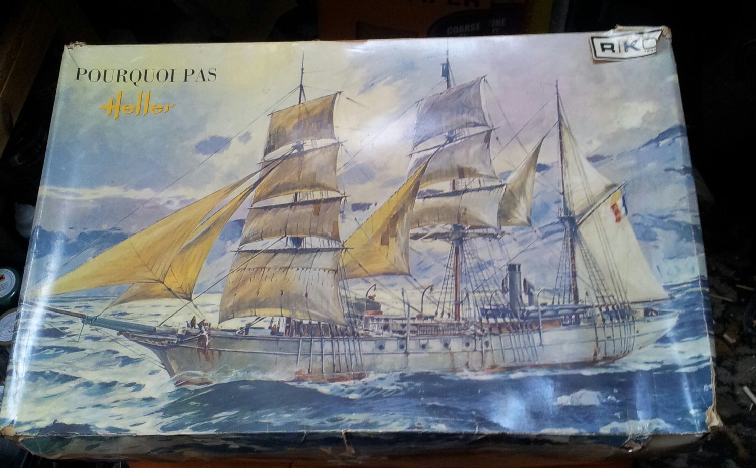
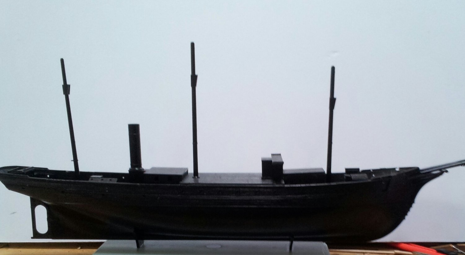
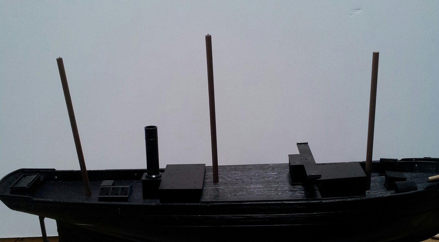
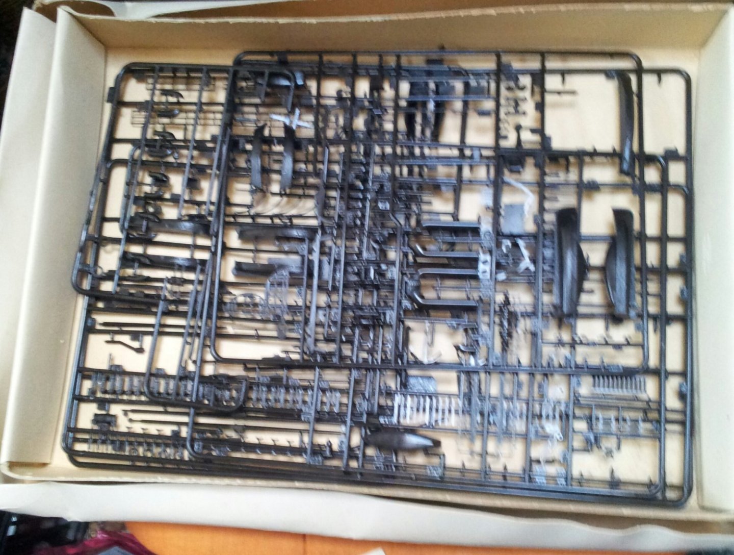
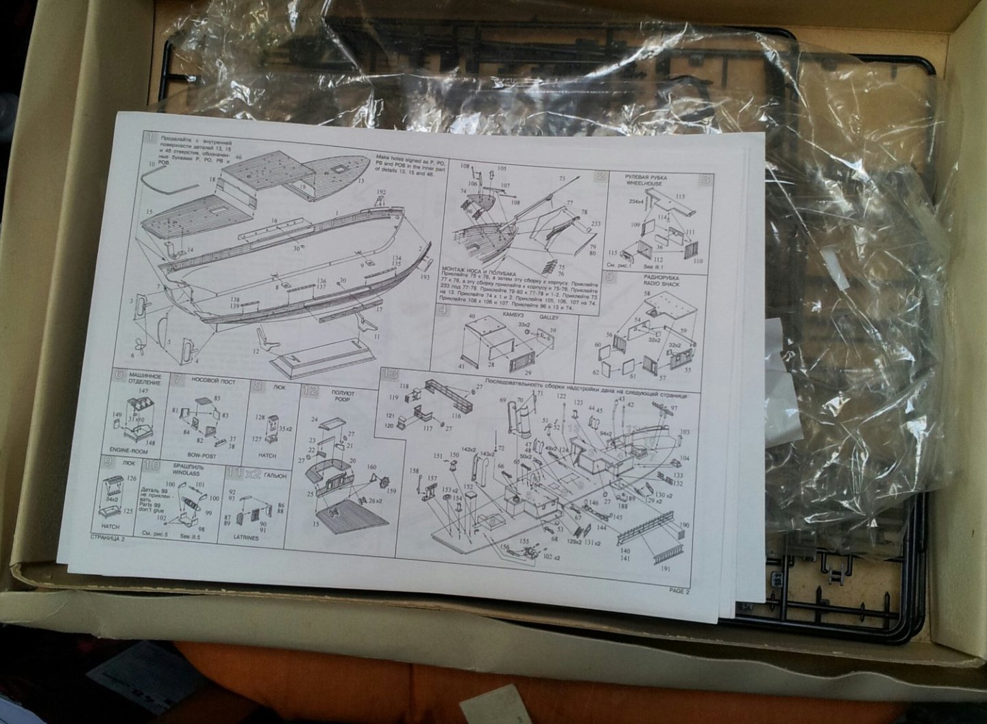
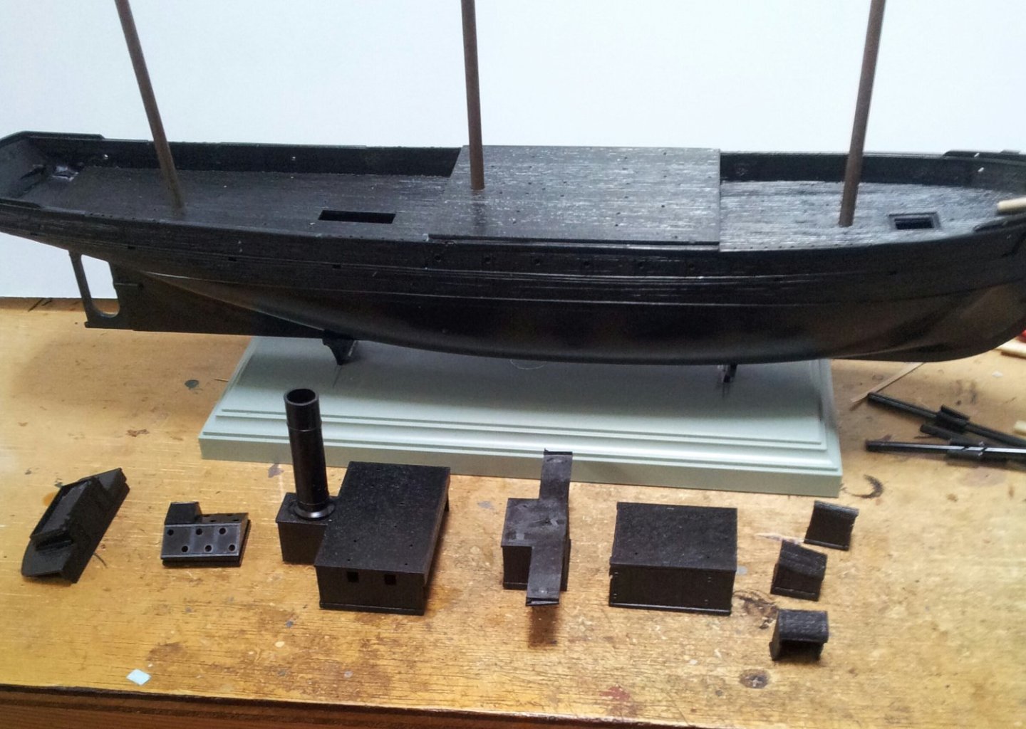
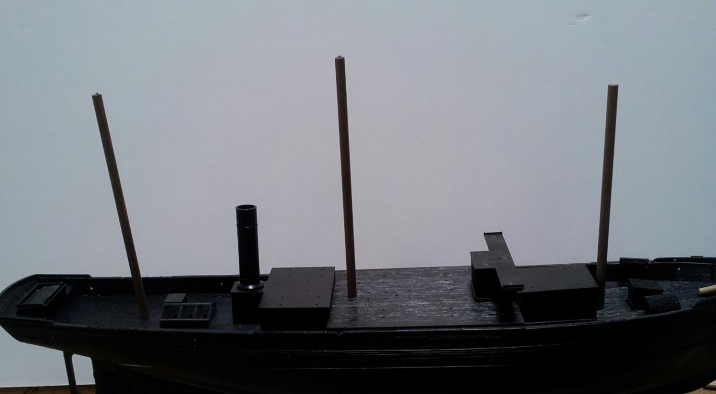
my interest in polar exploration vessels continues! seen this on a popular auction site and couldnt resist😁. While i will be using the kits hull and superstructure i will be replacing the masts and yards with walnut dowelling and will use model aircraft tissue for the sails (first time doing this so heres hoping)! Everything was in the kit except for the stand and transfers and the seller had printed out a copy of the Zvezda instructions who took over this kit! Pic 1- box art pic 2 and 3 inside the box pic 4- progress so far and plastic kit lower masts pic 5- superstructure sub assemblies pic 6- with walnut lower masts cut to length The hull was warped and needed a lot of clamping while the glue set -probably down to where the kit was stored and the box looks like it was under a bit of weight- there are a few ejection pin marks to cure on some of the roofs but overall mouldings are good. Take care all Keith


- 22 replies
-
- 6
-
-
- Pourquois Pas
- Heller
- (and 1 more)
-
coming along nicely Greg- i have started the Heller kit but will start a build log (oh lord already have several builds ongoing in various logs)! Problem with the heller kit is the black plastic which doesn't help with aging eyesight🤪. I have just receieved walnut dowelling for the masts and spars along with 2 and 3mm deadeyes and blocks- oh my they are small! Keith
-
nice work on the bow plating hake. Keith
-
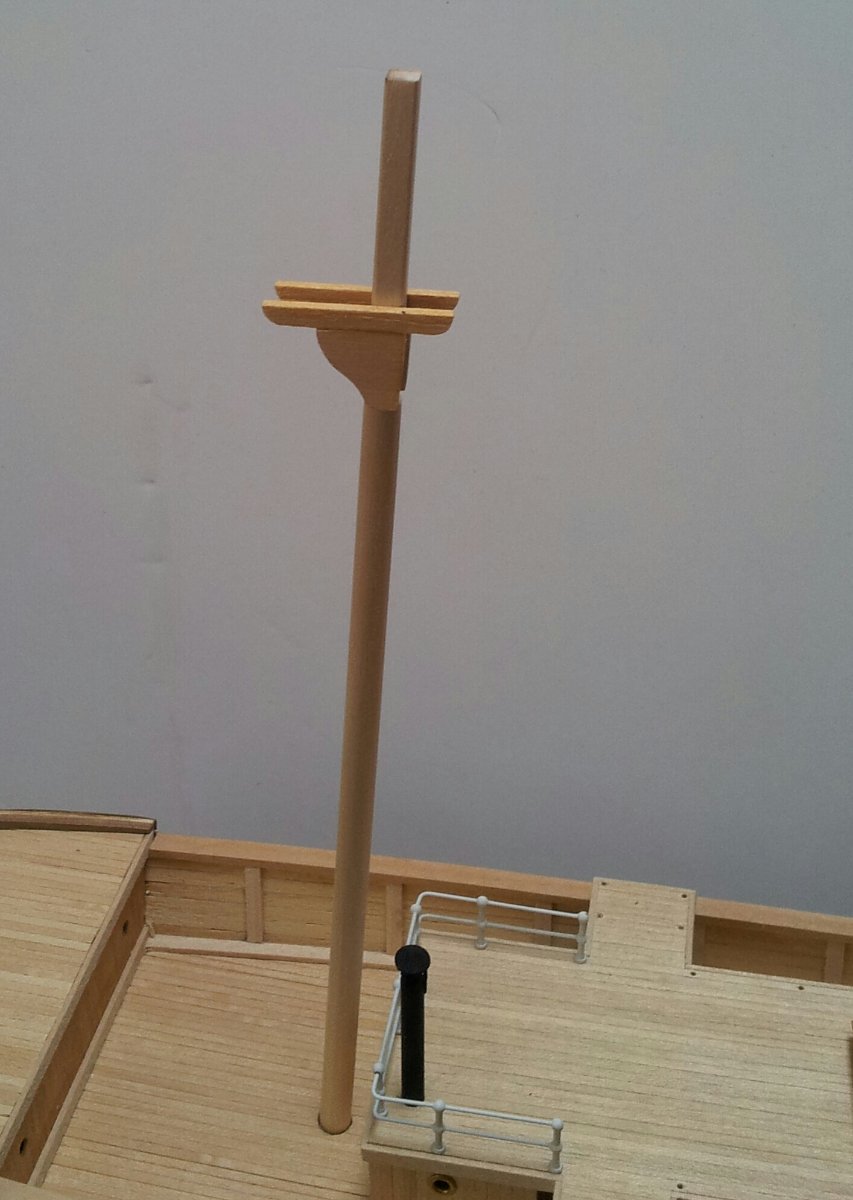
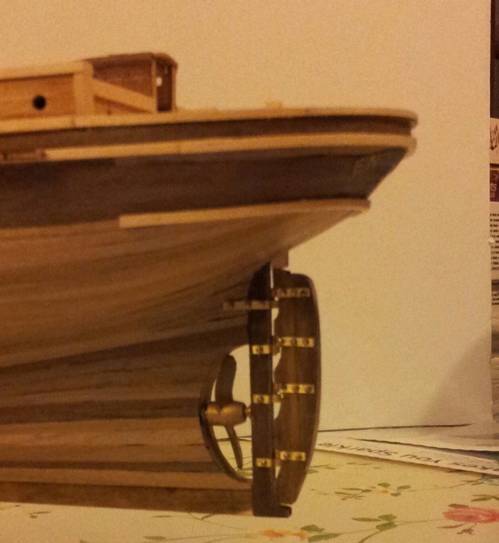
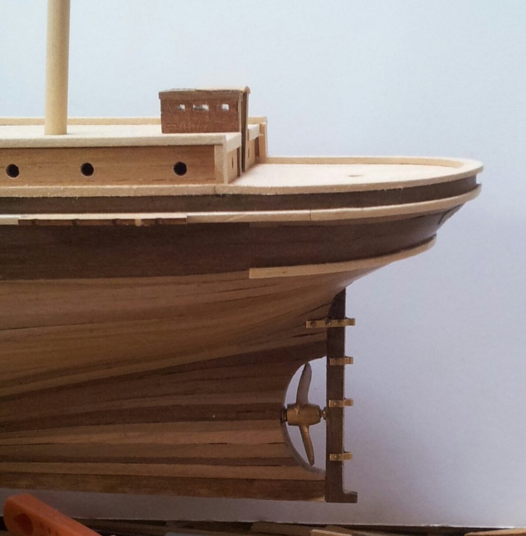
Wow the evenings are really closing in now- pitch black outside by 7pm today. Nice weather today but decided to have a rest from D.I.Y. work. I dug some brass strip out of my bits n pieces pile and made the rudder gudgeons- needed these done before more detail work was done to outside of hull. According to plans i bought from N.M.M. they should be 12mm apart (these are completely missing from occre plans/ fittings). Also made a start on the foremast with the masthead squared off and the bibs/ trestletrees added- again according to the plans the mast doubling should be around 30mm. Take care all Keith

-
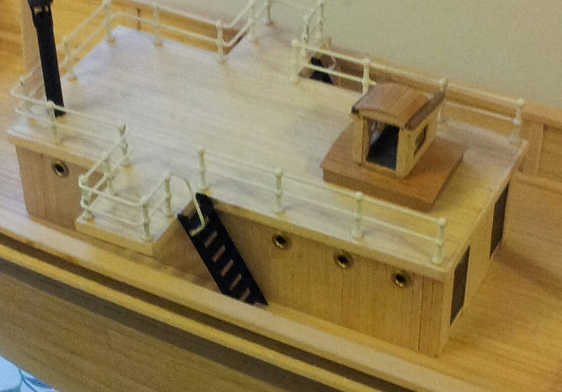
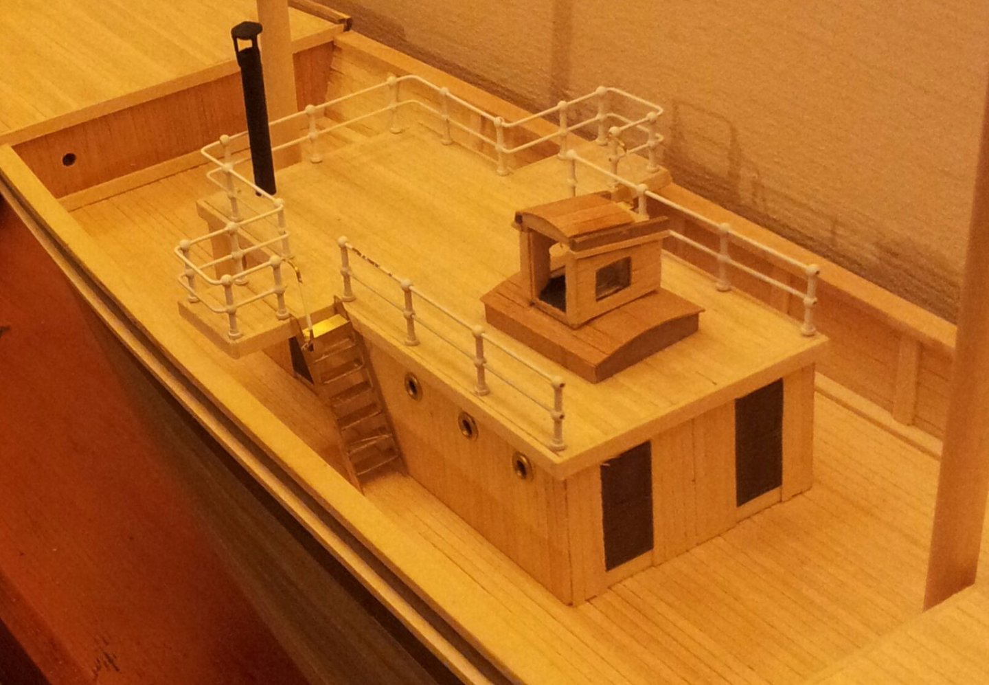
Thanks for looking in, bad weather again today so had some ship time- as a break from HMS Terror did a little work on Endurance with the lower masts /bowsprit cut to length and the access ladders for the bridge above "the ritz" built which will be painted before being fastened in place. I have also lowered the hatch cover on the ritz roof as it had too much wood tween the window and top. take care all Keith
-
don't forget humbrol clearfix Kev which was originally designed to make the windows in model airliners. Keith
-
looks good Hake- once painted will not be as in your face (if gluing/painting aluminium polish it and add paint and glue as soon as possible as it forms an oxidising layer very quickly which can affect the finish/ adherence). Keith