
MORE HANDBOOKS ARE ON THEIR WAY! We will let you know when they get here.
×


RichardG
-
Posts
695 -
Joined
-
Last visited
Content Type
Profiles
Forums
Gallery
Events
Everything posted by RichardG
-
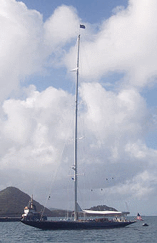
Whoa. And don't forget the flag (Endeavour in 2004) From https://en.wikipedia.org/wiki/Endeavour_(yacht) That's an amazingly tall mast. So maybe a floor to ceiling display case? I looks like you got just enough space for small bookshelf at the bottom. All the best, Richard
-
That is some impressive planking and tree nailing Richard.
-
Now here's a question with a million answers Consistent scale. I'd personally prefer 1/48th but that can get large really quickly. Smaller ships. No larger than 30 inches. Less than 24 would be better. Bigger may seem better but how many more incomplete Victory's do we need? Period: Sail to Steam would be an interesting period. For me 1750-1900's. Nationality: Don't care Building method: POB or POF. POF preferred if laser cut. Not solid. Materials: Wood . Top-quality wood can get very expensive - no clue how to solve that one. Cost: < $500. $200 would be better but it would have to be small to be that cheap. I would also like to see some opportunity for customization. I would assume there are ships where a number of them were built to the same basic plan but then had variations that could allow the building of a specific vessel. Richard.
-
TurboCad or graphics display help
RichardG replied to JohnLea's topic in CAD and 3D Modelling/Drafting Plans with Software
I don't think better hardware will help, or probably to be more accurate it can bring problems of its own and is expensive. A normal computer screen is 96 dpi (dots per inch) or 96 ppi (pixels per inch). When magnified a line will look like this: Some programs will use anti-aliasing to fill in the jaggies to make the line look smoother: However, a CAD program is interested in accuracy and speed, not looking good. The only way to get smoother lines is too increase the ppi of your monitor. You can get higher ppi monitors but they're more expensive and you might need a new graphics card as well. Then you may find the software doesn't handle the higher resolution very well and suddenly icons and menus are too small to use. When printing, the resolution will be at least 300 dpi and probably over 1200 dpi - then the jaggies will go. I hope this helps. Richard

-
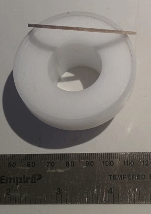
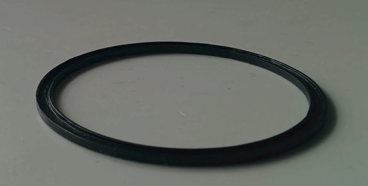
Well it's almost June - time to get back to the Dallas. I've been delayed by a mixture of work, another model (1/20th scale Tardis ), getting my garage cleaned out, planning, and of course the omnipresent procrastination. I'm finishing off a few deck items prior to starting the rigging. I've also decided to redo the masts, I think they can be improved. A the moment I'm doing the pivot gun, starting with the track. I had previously re-made this but was not entirely happy with the result. In the original model this was just a flat ring of plywood (this was destroyed when I removed the old deck). According to this site http://www.globalsecurity.org/military/systems/ship/sail-armament.htm, it should be "The pivot gun mount typically consisted of a metal ring, or 'circle' of from 9' to 12' in diameter, on deck and brought level athwartships by a wooden foundation. This circle was usually of iron, though copper and brass could be employed. The section of the circle was a shallow "U" shape, hollow side up, about 5 1/2" wide and 1" thick. The inside and outside rims of the top were raised 1/2" and were about 1/2" wide, creating a track in which the rollers traveled." I was fortunate to find a nylon bearing that made the construction a lot easier. I made rims from 1/64" plywood and the inside from 1/16" basswood. These all had thin tissue glued to the surface prior to cutting thin strips. The strips were then laid into the nylon bearing and glued. When dry, I was able to sand the ring so that is was thinner by using the bearing to hold it. A couple of coats of black paint and I have the best track I could do. According to the details in Chappelle's "The History of American Sailing Ships", a cutter this size often had a long-gun rather than the carronade supplied in the original kit. A long-gun is show on the plans in the book. So I am going to use a long-gun on the Dallas ( ). So now I'm off to make a gun carriage. Richard
- 78 replies
-
- 3
-

-
- dallas
- artesania latina
- (and 1 more)
-
TurboCad or graphics display help
RichardG replied to JohnLea's topic in CAD and 3D Modelling/Drafting Plans with Software
By zig-zag do you mean like this? If so, this is just a function of how the program draws lines on the screen where the accuracy is around 96 pixels per inch for the screen and a lot more accurate inside the program. When printed, the lines should be a lot smoother. Richard.
-
Toni, I got to see the model for real on Sunday. It's even more impressive! Richard.
-
I believe the stock would have been made from 2 pieces originally. Richard
- 3,618 replies
-
- 5
-
-
- young america
- clipper
- (and 1 more)
-
Looking really good . Richard.
-
Try these: http://www.shutterstock.com/s/derelict+boat/search.html http://www.alamy.com/stock-photo/wrecked-wooden.html http://www.gettyimages.com/photos/wrecked-wood-ships?excludenudity=false&family=creative&phrase=wrecked%20wood%20ships&sort=best http://www.istockphoto.com/photos/wrecked+wood+boat Richard.
-
Cutter Cheerful 1806 by rafine - FINISHED
RichardG replied to rafine's topic in - Build logs for subjects built 1801 - 1850
Excellent job. All the best, Richard.- 525 replies
-
- 3
-
-
- cheerful
- Syren Ship Model Company
- (and 1 more)
-
Cutter Cheerful 1806 by rafine - FINISHED
RichardG replied to rafine's topic in - Build logs for subjects built 1801 - 1850
Who cares about metal when they look that good - and they match the quality of the rest of the ship. Richard.- 525 replies
-
- 6
-
-
- cheerful
- Syren Ship Model Company
- (and 1 more)
-
Hof, No problem, I hope it works for you. As a beginner, it's good to be able to give a little back. Richard.
-
Hi Hof, I've attached a PDF with the planking pattern ready for printing. You'll find there are 2 pages. The first contains only full planks. The second has partial planks as well. I'm assuming the deck is longer than a single piece of A4. The second pages are designed to butt against each other to provide a continuous run. Please make sure you print them full size . I hope this helps. All the best, Richard. 4Butt100x5PlankingA4.pdf
-
I'm out of town today. I can get it to you tomorrow or Saturday. Richard.
-
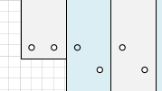
Hof, I created a 4-butt shift planking pattern for my 1/50 revenue cutter. I can easily adapt this for a 5mm plank and create a PDF. A few of questions though: What plank length do you want? Do you want treenails printed? If so, what spacing (I did mine evenly with the butt joints). What page size? (A4, ...) This is an enlarged sample (ignore the grid and colors - those are just to help with layout). Regards, Richard.
-
Is there anything you don't do really well? Richard.
- 641 replies
-
- 9
-
-
- greenwich hospital
- barge
- (and 1 more)
-
I hope everything goes well with your move. I'm looking forward to seeing this build - although my parents were not particularly interested in navel history (they were both in the RAF during WWII), this ship had a place in their hearts and some of that rubbed off on me. All the best, Richard
-
John, I would love a book like that. I am getting back to the rigging of my cutter after a long and somewhat unintended break.The problem is I read something, mostly understand it, but then can't remember it later. I'm using some home-grown software (a glorified notebook) to try and help me to be organized (see http://modelshipworld.com/index.php/topic/10451-first-time-rigging-being-organized/#entry313428). I was never any good at foreign languages at school either. Richard.
-
You can post links to the videos using the external link button https://www.youtube.com/watch?v=yLDJlm3Jkr8 https://www.youtube.com/watch?v=sgSZGMMu6gg When I just paste the links, I do see the embedded videos (in Chrome anyway). Richard. p.s. those will be some scary eyes!
-
You could check out this http://www.coomodel.com/info.asp?id=27. It's 1/6th scale, fully articulated. There seem to be quite a few on Ebay (search for coomodel bs003), Richard.
-
Wonderful. I have no clue how you manage to do all of this at such a small scale - so I'll just stare in amazement. Richard.